EP2998172A1 - Method for braking a trailer - Google Patents
Method for braking a trailer Download PDFInfo
- Publication number
- EP2998172A1 EP2998172A1 EP15185683.8A EP15185683A EP2998172A1 EP 2998172 A1 EP2998172 A1 EP 2998172A1 EP 15185683 A EP15185683 A EP 15185683A EP 2998172 A1 EP2998172 A1 EP 2998172A1
- Authority
- EP
- European Patent Office
- Prior art keywords
- trailer
- braking
- towing vehicle
- engine speed
- braking torque
- Prior art date
- Legal status (The legal status is an assumption and is not a legal conclusion. Google has not performed a legal analysis and makes no representation as to the accuracy of the status listed.)
- Withdrawn
Links
Images
Classifications
-
- B—PERFORMING OPERATIONS; TRANSPORTING
- B60—VEHICLES IN GENERAL
- B60T—VEHICLE BRAKE CONTROL SYSTEMS OR PARTS THEREOF; BRAKE CONTROL SYSTEMS OR PARTS THEREOF, IN GENERAL; ARRANGEMENT OF BRAKING ELEMENTS ON VEHICLES IN GENERAL; PORTABLE DEVICES FOR PREVENTING UNWANTED MOVEMENT OF VEHICLES; VEHICLE MODIFICATIONS TO FACILITATE COOLING OF BRAKES
- B60T7/00—Brake-action initiating means
- B60T7/12—Brake-action initiating means for automatic initiation; for initiation not subject to will of driver or passenger
- B60T7/20—Brake-action initiating means for automatic initiation; for initiation not subject to will of driver or passenger specially for trailers, e.g. in case of uncoupling of or overrunning by trailer
-
- B—PERFORMING OPERATIONS; TRANSPORTING
- B60—VEHICLES IN GENERAL
- B60T—VEHICLE BRAKE CONTROL SYSTEMS OR PARTS THEREOF; BRAKE CONTROL SYSTEMS OR PARTS THEREOF, IN GENERAL; ARRANGEMENT OF BRAKING ELEMENTS ON VEHICLES IN GENERAL; PORTABLE DEVICES FOR PREVENTING UNWANTED MOVEMENT OF VEHICLES; VEHICLE MODIFICATIONS TO FACILITATE COOLING OF BRAKES
- B60T8/00—Arrangements for adjusting wheel-braking force to meet varying vehicular or ground-surface conditions, e.g. limiting or varying distribution of braking force
- B60T8/17—Using electrical or electronic regulation means to control braking
- B60T8/1701—Braking or traction control means specially adapted for particular types of vehicles
- B60T8/1708—Braking or traction control means specially adapted for particular types of vehicles for lorries or tractor-trailer combinations
-
- B—PERFORMING OPERATIONS; TRANSPORTING
- B60—VEHICLES IN GENERAL
- B60T—VEHICLE BRAKE CONTROL SYSTEMS OR PARTS THEREOF; BRAKE CONTROL SYSTEMS OR PARTS THEREOF, IN GENERAL; ARRANGEMENT OF BRAKING ELEMENTS ON VEHICLES IN GENERAL; PORTABLE DEVICES FOR PREVENTING UNWANTED MOVEMENT OF VEHICLES; VEHICLE MODIFICATIONS TO FACILITATE COOLING OF BRAKES
- B60T2260/00—Interaction of vehicle brake system with other systems
- B60T2260/04—Automatic transmission
Definitions
- the invention relates to a method for braking a trailer in a towing vehicle-trailer combination, wherein the towing vehicle comprises a traction drive and arranged in the traction drive transmission device and a translation of the transmission device influencing propulsion control device and the trailer at least one driving axle, via which by driving over the towing vehicle at least one braking torque can be transmitted to a busy ground surface.
- Tractor-to-trailer trailers which may be a tractor, in particular, regularly include brake systems in which a pneumatic trailer brake valve is hydraulically actuated via the tractor when the tractor's brake pedal is actuated.
- a pneumatic trailer brake valve is hydraulically actuated via the tractor when the tractor's brake pedal is actuated.
- the time of Bremsaktutechnik the trailer and the braking force or the generated braking torque on the trailer are relevant to the driving stability of the team. Since the tractor and the trailer are connected to each other via the trailer hitch, there is a postponement of the trailer on the tractor when the brake of the tractor responds earlier or their braking force is greater than that of the brake of the trailer. Such a driving condition can be detrimental to the driving stability of the team.
- tractors increasingly use steplessly switchable or automatically switchable transmissions, in which the tractor can be decelerated solely by adjusting a driving lever.
- An adjustment of the drive lever in one of the two possible directions causes a change in the gear ratio to a larger translation, so that a larger engine braking torque leads to a larger braking torque to the drive axle. Since during this braking neither the brakes of the tractor nor the trailer are operated, so only the engine braking torque on the drive axle of the tractor is effective, a postponement occurs of the trailer on the tractor with possibly negative consequences for the driving stability of the team.
- the beats DE 10 2005 002 699 A1 a arranged in the coupling of the tractor or the trailer casserole sensor that generates an electrical signal that represents a braking force generated by the tractor by the driving lever by the driving lever.
- the brakes of the trailer are actuated via a brake valve.
- this is a mechanical overrun brake, with the disadvantage that, in principle, the trailer must first run onto the towing vehicle before the need for trailer braking can be sensed.
- the object of the present invention is to provide a method with which an improved trailer braking can be achieved.
- the object is achieved by a method for braking a trailer in a towing vehicle-trailer combination, wherein the towing vehicle comprises a traction drive train and arranged in the traction drive transmission device and a translation of the transmission device influencing propulsion control device and the trailer at least one driving axle, through which Triggering via the towing vehicle at least one braking torque can be transmitted to a busy ground surface, in which the driving axis of the trailer is driven to transmit a braking torque on the ground surface driven, as long as a continuously detected actual value of an engine speed at an actuation of the propulsion control device to increase the translation of the Transmission device detected setpoint exceeds an engine speed.
- the driving lever is understood by the driving control device with which a gear ratio of the gear device can be adjusted.
- the transmission device may be part of a so-called engine transmission management system, via which parameters such as the engine speed can be preset, so that a preset speed level is kept at least largely constant by a control.
- the method according to the invention provides a control which controls a braking torque which a trailer applies to the traveled ground surface via its driving axis, as a function of the position of the driving lever and the engine speed of the towing vehicle.
- Targeted control of the trailer's deceleration avoids or reduces the tractor's pushing the tractor so as to increase driving stability. If the operator of the tractor by adjusting the control lever delays the trailer, during the deceleration process, the trailer is also actively braked or delayed.
- an actual value of a state variable characterizing an engine load of an internal combustion engine of the traction drive train is detected via an electronic control unit of the traction vehicle as long as the actual value of an engine speed exceeds the nominal value of an engine speed.
- an additional decision criterion for a control of the driving axle for transmitting a braking torque is provided.
- the driving axis of the trailer for the transmission of a braking torque is controlled, as long as the motor load characterizing state variable falls below a threshold.
- an actuation position of the propulsion control device and the engine speed are detected via an electronic control unit of the towing vehicle.
- the operating position and the engine speed via the control unit in a CAN bus system are available in which the control unit is regularly incorporated.
- the transmission device of the traction vehicle is preferably a continuously variable or an automatically shiftable transmission. Such transmissions are easy to integrate into an engine transmission management system. Alternatively, the transmission device may also be a manual transmission manual transmission. When the operator switches back downhill, the trailer pushes and the engine speed increases. In this case, the driving axis of the trailer can be controlled to transmit a braking torque, so that the driving stability is increased.
- the method according to the invention is used in a first embodiment, in which the driving axis of the trailer can be controlled via the towing vehicle Operational braking device comprises to transmit a braking torque on a busy ground surface.
- a brake pressure is actuated in the service brake device, which causes a braking torque on the driving axle.
- the service brake device is pneumatically operated. This is the predominant type of actuation in trailer brakes and thus easy to integrate into the process sequence according to the invention.
- the service brake device can also be operated hydraulically, electrically, mechanically or by combinations thereof.
- the method according to the invention is preferably used in an alternative embodiment, in which the travel axis of the trailer is an electrically driven or a hydraulically driven drive axle.
- a braking torque can be applied to the drive axle in a simple manner by applying an oppositely directed drive torque via the electric drive or the hydraulic drive.
- a brake torque to be controlled of the driving axis of the trailer is determined from a difference between actual value and desired value of the engine speed. Furthermore, it is preferred that the brake torque to be controlled is determined via a proportional-integral controller.
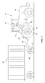
- the FIG. 1 shows a tractor 10 in the form of a tractor, which is connected via a detachable drawbar 42 with a trailer 40.
- the traction vehicle 10 includes a traction drive train 12 consisting of an internal combustion engine 14, a transmission device 16 and a drive axle 18 with drive wheels 20. Further, an electronic control unit 22 is provided with the internal combustion engine 14, the transmission device 16, a propulsion control device 24 and an input control element 26 is in a control connection.
- the propulsion control device 24 and the input control element 26 are arranged in a cabin 28 in the access area of an operator who is there.
- the propulsion control device 24 is designed in the form of a driving lever, with which a translation of the transmission device 16 can be selected by the operator, which will be explained in more detail below.
- the internal combustion engine 14, the transmission device 16, the electronic control unit 22, the drive lever 24, and the input operator 26 can be understood as part of an engine-transmission management system through which various settings concerning the vehicle driveline 12 can be made and preselected.
- an engine speed can be selected via the input control element 26, so that the internal combustion engine 14 runs until the setting of a changed engine speed with the selected speed.
- the operator can now indirectly via an adjustment of the translation of the transmission device 16 select a driving speed or influence this. If the operator has therefore selected an engine speed so that the tractor moves at a given operating position of the driving lever 24 with the corresponding driving speed, the operator can change the driving speed of the tractor by changing the operating position of the driving lever 24 and thus by changing the ratio of the transmission device 16 10 effect.
- the trailer 40 comprises at least one driving axle 44 and, as described here by way of example, can be designed as a loading wagon.
- the loader wagon may be equipped with a service brake device 46 in a first embodiment.
- the service brake device 46 can be designed as a pneumatically actuated system.
- the service brake device 46 is arranged predominantly in the region of a drive axle 44 and can be constructed in a known manner. It can be provided another driving axle. In the area of the further driving axle, a further service brake device can be arranged.
- brake cylinders may be provided in which a pneumatic brake pressure can be generated, so that in the brake cylinders einitzende brake piston act on friction linings against a friction surface in a brake drum or on a brake disc.
- the drive axle 44 transmits a braking torque to the currently traveled ground surface so that a deceleration acts on the trailer 40.
- a trailer brake valve 30 that can be controlled electrically via the electronic control unit 22 is provided on the tractor 10.
- the electrically controllable trailer brake valve 30 is given the opportunity to independently control the service brake device 46 of the trailer 40 of a service brake device of the tractor 10 and dynamically adjust the brake pressure in the service brake device 46 of the trailer 40.
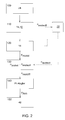
- the inventive method for braking a trailer in a tractor-trailer combination is in its course in the FIG. 2 shown and is used when the operator sets without actuation of the service brake device of the tractor 10 via the drive lever 24, a higher gear ratio for braking the team.
- the operator moves the drive lever 24 in the direction of a larger gear ratio of the transmission device 16 during the drive of the vehicle.
- the current engine speed n->oll of the internal combustion engine 14 is calculated as a desired value and stored in the electronic control unit 22.
- the tractor 10 decelerates and the trailer 40 runs on the tractor 10.
- the engine speed of the internal combustion engine 14 increases during deceleration.
- step 120 the course of the current engine speed n motist is continuously recorded by the electronic control unit 22 as the actual value and in method step 130 a difference value n motdiff calculated to the setpoint of the engine speed n 1925oll .
- the difference value n motdiff from the setpoint value and the actual value of the engine speed n adoptedoll , n motist is fed to a proportional-integral controller in method step 140.
- the proportional-integral controller calculates, based on the difference value n motdiff of the rotational speeds, a pneumatic brake pressure p Anh of the service brake device 46 of the trailer 40, which must be effective in order to avoid or at least reduce the attachment of the trailer 40 to the tractor 10.
- the service brake device 46 of the trailer 40 is activated in method step 150. As soon as the difference value n motdiff of the rotational speeds has fallen to zero, the service brake device 46 of the trailer 40 is no longer actuated with a brake pressure.
- the trailer 40 which can also be designed here as a loader wagon, have an electrically driven or hydraulically driven drive axle as the driving axle 44.
- an electrically driven or hydraulically driven drive axle as the driving axle 44.
- a drive axle does not have a separate service brake system. Rather, in such drive axles, a braking torque can be transmitted to the currently traveled ground surface, in that the drive axle applies an opposing drive torque relative to the instantaneous direction of movement.
Landscapes
- Engineering & Computer Science (AREA)
- Transportation (AREA)
- Mechanical Engineering (AREA)
- Regulating Braking Force (AREA)
- Control Of Driving Devices And Active Controlling Of Vehicle (AREA)
Abstract
Die Erfindung betrifft ein Verfahren zur Bremsung eines Anhängers in einem Zugfahrzeug-Anhänger-Gespann, bei dem eine Fahrachse (44) des Anhängers (40) zur Übertragung eines Bremsmoments auf die befahrene Bodenoberfläche angesteuert wird, solange ein kontinuirlich erfasster Istwert einer Motordrehzahl einen bei einer Betätigung einer Vortriebssteuereinrichtung (24) zur Erhöhung der Übersetzung einer Getriebevorrichtung (16) des Zugfahrzeugs erfassten Sollwert einer Motordrehzahl übersteigt.The invention relates to a method for braking a trailer in a towing vehicle-trailer combination, in which a driving axis (44) of the trailer (40) is driven to transmit a braking torque to the ground surface driven, as long as a continuously detected actual value of an engine speed at a Actuation of a propulsion control device (24) to increase the ratio of a transmission device (16) of the towing vehicle detected setpoint exceeds an engine speed.
Description
Die Erfindung betrifft ein Verfahren zur Bremsung eines Anhängers in einem Zugfahrzeug-Anhänger-Gespann, wobei das Zugfahrzeug einen Fahrantriebsstrang und eine in dem Fahrantriebsstrang angeordnete Getriebevorrichtung und eine eine Übersetzung der Getriebevorrichtung beeinflussende Vortriebssteuereinrichtung und der Anhänger zumindest eine Fahrachse umfasst, über die durch Ansteuerung über das Zugfahrzeug zumindest ein Bremsmoment auf eine befahrene Bodenoberfläche übertragen werden kann.The invention relates to a method for braking a trailer in a towing vehicle-trailer combination, wherein the towing vehicle comprises a traction drive and arranged in the traction drive transmission device and a translation of the transmission device influencing propulsion control device and the trailer at least one driving axle, via which by driving over the towing vehicle at least one braking torque can be transmitted to a busy ground surface.
Regelmäßig weisen Zugfahrzeug-Anhänger-Gespanne, wobei das Zugfahrzeug insbesondere ein Traktor sein kann, Bremssysteme auf, bei denen ein pneumatisches Anhängerbremsventil hydraulisch über den Traktor angesteuert wird, wenn das Bremspedal des Traktors betätigt wird. Bei einer Bremsung des Gespanns sind der Zeitpunkt der Bremsaktuierung am Anhänger und die Bremskraft bzw. das erzeugte Bremsmoment am Anhänger relevant für die Fahrstabilität des Gespanns. Da der Traktor und der Anhänger über die Anhängerkupplung miteinander verbunden sind, kommt es zu einem Aufschieben des Anhängers auf den Traktor, wenn die Bremse des Traktors früher anspricht oder deren Bremskraft größer als die der Bremse des Anhängers ist. Ein derartiger Fahrzustand kann der Fahrstabilität des Gespanns abträglich sein.Tractor-to-trailer trailers, which may be a tractor, in particular, regularly include brake systems in which a pneumatic trailer brake valve is hydraulically actuated via the tractor when the tractor's brake pedal is actuated. When braking the team, the time of Bremsaktuierung the trailer and the braking force or the generated braking torque on the trailer are relevant to the driving stability of the team. Since the tractor and the trailer are connected to each other via the trailer hitch, there is a postponement of the trailer on the tractor when the brake of the tractor responds earlier or their braking force is greater than that of the brake of the trailer. Such a driving condition can be detrimental to the driving stability of the team.
In der jüngeren Vergangenheit kommen in Traktoren vermehrt stufenlos schaltbare oder automatisiert schaltbare Getriebe zum Einsatz, bei denen sich der Traktor allein durch Verstellen eines Fahrhebels verzögern lässt. Ein Verstellen des Fahrhebels in einer der beiden möglichen Richtungen bewirkt eine Änderung der Getriebeübersetzung hin zu einer größeren Übersetzung, so dass ein größeres Motorbremsmoment zu einem größeren Bremsmoment an der Antriebsachse führt. Da bei dieser Bremsung weder die Bremsen des Traktors noch des Anhängers betätigt werden, also lediglich das Motorbremsmoment über die Antriebsachse des Traktors wirksam ist, erfolgt ein Aufschieben des Anhängers auf den Traktor mit möglicherweise negativen Folgen für die Fahrstabilität des Gespanns.In the recent past, tractors increasingly use steplessly switchable or automatically switchable transmissions, in which the tractor can be decelerated solely by adjusting a driving lever. An adjustment of the drive lever in one of the two possible directions causes a change in the gear ratio to a larger translation, so that a larger engine braking torque leads to a larger braking torque to the drive axle. Since during this braking neither the brakes of the tractor nor the trailer are operated, so only the engine braking torque on the drive axle of the tractor is effective, a postponement occurs of the trailer on the tractor with possibly negative consequences for the driving stability of the team.
Hierzu schlägt die
Ausgehend hiervon besteht die Aufgabe der vorliegenden Erfindung darin ein Verfahren bereitzustellen, mit dem eine verbesserte Anhängerbremsung erreicht werden kann.Based on this, the object of the present invention is to provide a method with which an improved trailer braking can be achieved.
Die Aufgabe wird gelöst durch ein Verfahren zur Bremsung eines Anhängers in einem Zugfahrzeug-Anhänger-Gespann, wobei das Zugfahrzeug einen Fahrantriebsstrang und eine in dem Fahrantriebsstrang angeordnete Getriebevorrichtung und eine eine Übersetzung der Getriebevorrichtung beeinflussende Vortriebssteuereinrichtung und der Anhänger zumindest eine Fahrachse umfasst, über die durch Ansteuerung über das Zugfahrzeug zumindest ein Bremsmoment auf eine befahrene Bodenoberfläche übertragen werden kann, bei dem die Fahrachse des Anhängers zur Übertragung eines Bremsmoments auf die befahrene Bodenoberfläche angesteuert wird, solange ein kontinuierlich erfasster Istwert einer Motordrehzahl einen bei einer Betätigung der Vortriebssteuereinrichtung zur Erhöhung der Übersetzung der Getriebevorrichtung erfassten Sollwert einer Motordrehzahl übersteigt.The object is achieved by a method for braking a trailer in a towing vehicle-trailer combination, wherein the towing vehicle comprises a traction drive train and arranged in the traction drive transmission device and a translation of the transmission device influencing propulsion control device and the trailer at least one driving axle, through which Triggering via the towing vehicle at least one braking torque can be transmitted to a busy ground surface, in which the driving axis of the trailer is driven to transmit a braking torque on the ground surface driven, as long as a continuously detected actual value of an engine speed at an actuation of the propulsion control device to increase the translation of the Transmission device detected setpoint exceeds an engine speed.
Hierbei wird unter Vortriebssteuereinrichtung der Fahrhebel verstanden, mit dem eine Übersetzung der Getriebevorrichtung eingestellt werden kann. Weiterhin kann die Getriebevorrichtung teil eines sogenannten Motor-Getriebe-Management-Systems sein, über das Parameter wie beispielsweise die Motordrehzahl voreingestellt werden können, so dass ein voreingestelltes Drehzahlniveau von einer Regelung zumindest weitestgehend konstant gehalten wird.In this case, the driving lever is understood by the driving control device with which a gear ratio of the gear device can be adjusted. Furthermore, the transmission device may be part of a so-called engine transmission management system, via which parameters such as the engine speed can be preset, so that a preset speed level is kept at least largely constant by a control.
Durch das erfindungsgemäße Verfahren wird eine Steuerung bereitgestellt, die ein Bremsmoment, das ein Anhänger über seine Fahrachse auf die befahrene Bodenoberfläche aufbringt, in Abhängigkeit der Position des Fahrhebels und der Motordrehzahl des Zugfahrzeugs steuert. Durch eine gezielte Steuerung der Verzögerung des Anhängers wird ein Schieben des Traktors durch den Anhänger vermieden bzw. reduziert, um so die Fahrstabilität zu erhöhen. Wenn die Bedienperson des Traktors durch Verstellen des Fahrhebels das Gespann verzögert, wird während des Verzögerungsvorgangs der Anhänger ebenfalls aktiv abgebremst bzw. verzögert.The method according to the invention provides a control which controls a braking torque which a trailer applies to the traveled ground surface via its driving axis, as a function of the position of the driving lever and the engine speed of the towing vehicle. Targeted control of the trailer's deceleration avoids or reduces the tractor's pushing the tractor so as to increase driving stability. If the operator of the tractor by adjusting the control lever delays the trailer, during the deceleration process, the trailer is also actively braked or delayed.
Bevorzugt wird ein Istwert einer eine Motorlast einer Verbrennungskraftmaschine des Fahrantriebsstrangs charakterisierende Zustandsgröße über eine elektronische Kontrolleinheit des Zugfahrzeugs erfasst, solange der Istwert einer Motordrehzahl den Sollwert einer Motordrehzahl übersteigt. Hierdurch wird noch ein zusätzliches Entscheidungskriterium für eine Ansteuerung der Fahrachse zur Übertragung eines Bremsmoments bereitgestellt. Bevorzugt wird die Fahrachse des Anhängers zur Übertragung eines Bremsmoments angesteuert, solange die die Motorlast charakterisierende Zustandsgröße einen Schwellenwert unterschreitet.Preferably, an actual value of a state variable characterizing an engine load of an internal combustion engine of the traction drive train is detected via an electronic control unit of the traction vehicle as long as the actual value of an engine speed exceeds the nominal value of an engine speed. As a result, an additional decision criterion for a control of the driving axle for transmitting a braking torque is provided. Preferably, the driving axis of the trailer for the transmission of a braking torque is controlled, as long as the motor load characterizing state variable falls below a threshold.
Bevorzugt werden eine Betätigungsstellung der Vortriebssteuereinrichtung und die Motordrehzahl über eine elektronische Kontrolleinheit des Zugfahrzeugs erfasst. Hier sind die Betätigungsstellung und die Motordrehzahl über die Kontrolleinheit in einem CAN-Bussystem verfügbar, in dem die Kontrolleinheit regelmäßig eingebunden ist.Preferably, an actuation position of the propulsion control device and the engine speed are detected via an electronic control unit of the towing vehicle. Here, the operating position and the engine speed via the control unit in a CAN bus system are available in which the control unit is regularly incorporated.
Bevorzugt handelt es sich bei der Getriebevorrichtung des Zugfahrzeug um ein stufenlos schaltbares oder ein automatisiert schaltbares Getriebe. Derartige Getriebe sind einfach in ein Motor-Getriebe-Management-System zu integrieren. Alternativ kann es sich bei der Getriebevorrichtung auch um ein Schaltgetrieben mit manuellen Schaltvorgängen handeln. Wenn die Bedienperson bei der Bergabfahrt zurückschaltet schiebt der Anhänger und die Motordrehzahl erhöht sich. In diesem Fall kann die Fahrachse des Anhängers zur Übertragung eines Bremsmoments angesteuert, so dass die Fahrstabilität erhöht wird.The transmission device of the traction vehicle is preferably a continuously variable or an automatically shiftable transmission. Such transmissions are easy to integrate into an engine transmission management system. Alternatively, the transmission device may also be a manual transmission manual transmission. When the operator switches back downhill, the trailer pushes and the engine speed increases. In this case, the driving axis of the trailer can be controlled to transmit a braking torque, so that the driving stability is increased.
Bevorzugt kommt das erfindungsgemäße Verfahren bei einer ersten Ausführungsform zur Anwendung, bei der die Fahrachse des Anhängers eine über das Zugfahrzeug ansteuerbare Betriebsbremseinrichtung umfasst, um ein Bremsmoment auf eine befahrene Bodenoberfläche zu übertragen. Hierbei wird in der Betriebsbremseinrichtung ein Bremsdruck angesteuert, der ein Bremsmoment an der Fahrachse bewirkt.Preferably, the method according to the invention is used in a first embodiment, in which the driving axis of the trailer can be controlled via the towing vehicle Operational braking device comprises to transmit a braking torque on a busy ground surface. In this case, a brake pressure is actuated in the service brake device, which causes a braking torque on the driving axle.
Bevorzugt ist die Betriebsbremseinrichtung pneumatisch betätigt. Dies ist die vorherrschende Betätigungsart bei Anhängerbremsen und somit leicht in den erfindungsgemäßen Verfahrensablauf zu integrieren. Alternativ kann die Betriebsbremseinrichtung auch hydraulisch, elektrisch, mechanisch oder durch Kombinationen hiervon betrieben werden.Preferably, the service brake device is pneumatically operated. This is the predominant type of actuation in trailer brakes and thus easy to integrate into the process sequence according to the invention. Alternatively, the service brake device can also be operated hydraulically, electrically, mechanically or by combinations thereof.
Bevorzugt kommt das erfindungsgemäße Verfahren bei einer alternativen Ausführungsform zur Anwendung, bei der es sich bei der Fahrachse des Anhängers um eine elektrisch angetriebene oder eine hydraulisch angetriebene Triebachse handelt. Hierdurch kann in einfacher Weise ein Bremsmoment auf die Fahrachse aufgebracht werden, indem ein entgegensetzt gerichtetes Antriebsmoment über den elektrischen Antrieb oder den hydraulischen Antrieb aufgebracht wird.The method according to the invention is preferably used in an alternative embodiment, in which the travel axis of the trailer is an electrically driven or a hydraulically driven drive axle. As a result, a braking torque can be applied to the drive axle in a simple manner by applying an oppositely directed drive torque via the electric drive or the hydraulic drive.
Bevorzugt wird aus einer Differenz von Istwert zu Sollwert der Motordrehzahl ein anzusteuerndes Bremsmoment der Fahrachse des Anhängers ermittelt. Weiterhin ist bevorzugt, dass das anzusteuernde Bremsmoment über einen Proportional-Integral-Regler ermittelt wird.Preferably, a brake torque to be controlled of the driving axis of the trailer is determined from a difference between actual value and desired value of the engine speed. Furthermore, it is preferred that the brake torque to be controlled is determined via a proportional-integral controller.
Die Erfindung wird nachfolgend anhand der beigefügten Figuren beschrieben. Hierin zeigen
- Figur 1
- ein Zugfahrzeug-Anhänger-Gespann und
- Figur 2
- ein Ablaufdiagramm des erfindungsgemäßen Verfahrens zur Bremsung eines Anhängers.
- FIG. 1
- a towing vehicle trailer team and
- FIG. 2
- a flow diagram of the method according to the invention for braking a trailer.
Die
Die Verbrennungskraftmaschine 14, die Getriebevorrichtung 16, die elektronische Kontrolleinheit 22, der Fahrhebel 24 und das Eingabebedienelement 26 können als Teil eines Motor-Getriebe-Management-Systems begriffen werden, über das diverse den Fahrantriebsstrang 12 betreffende Einstellungen gemacht und vorausgewählt werden können. So kann beispielsweise über das Eingabebedienelement 26 eine Motordrehzahl ausgewählt werden, so dass die Verbrennungskraftmaschine 14 bis zur Einstellung einer geänderten Motordrehzahl mit der ausgewählten Drehzahl läuft. Über den Fahrhebel 24 kann die Bedienperson nun mittelbar über eine Verstellung der Übersetzung der Getriebevorrichtung 16 eine Fahrgeschwindigkeit auswählen bzw. diese beeinflussen. Hat die Bedienperson demnach eine Motordrehzahl ausgewählt, so dass sich der Traktor bei einer gegebenen Betätigungsstellung des Fahrhebels 24 mit entsprechender Fahrgeschwindigkeit bewegt, kann die Bedienperson durch Änderung der Betätigungsstellung des Fahrhebels 24 und damit durch Änderung der Übersetzung der Getriebevorrichtung 16 ein Änderung der Fahrgeschwindigkeit des Traktors 10 bewirken. Im Kontext dieser Beschreibung steht eine Reduzierung der Fahrgeschwindigkeit des Traktors 10 beziehungsweise des Traktor-Anhänger-Gespanns im Vordergrund, die dadurch erreicht wird, dass bei konstant gehaltener Motordrehzahl der Fahrhebel 24 in eine Betätigungsstellung gebracht wird, die einer größeren Übersetzung der Getriebevorrichtung 16 entspricht. Hierdurch wird ausgehend von der Verbrennungskraftmaschine 14 ein Motorbremsmoment über die Getriebevorrichtung 16 und die Antriebsachse 18 auf die Antriebsräder 20 übertragen, so dass eine Bremsung des Traktors 10 beziehungsweise des Traktor-Anhänger-Gespanns erfolgt.The
Der Anhänger 40 umfasst zumindest eine Fahrachse 44 und kann wie vorliegend beispielhaft beschrieben als Ladewagen ausgeführt sein. Hierbei kann der Ladewagen in einer ersten Ausführungsform mit einer Betriebsbremseinrichtung 46 ausgestattet sein. Die Betriebsbremseinrichtung 46 kann als pneumatisch betätigbare Anlage ausgeführt sein. Die Betriebsbremseinrichtung 46 ist überwiegend im Bereich einer Fahrachse 44 angeordnet und kann in bekannter Weise aufgebaut sein. Es kann eine weitere Fahrachse vorgesehen sein. Im Bereich der weiteren Fahrachse kann eine weitere Betriebsbremseinrichtung angeordnet sein. Insbesondere können Bremszylinder vorgesehen sein, in denen pneumatisch ein Bremsdruck erzeugt werden kann, so dass in den Bremszylindern einsitzende Bremskolben Reibbeläge gegen eine Reibfläche in einer Bremstrommel oder auf einer Bremsscheibe beaufschlagen. In der Folge überträgt die Fahrachse 44 ein Bremsmoment auf die momentan befahrene Bodenoberfläche, so dass eine Verzögerung auf den Anhänger 40 wirkt.The
Zur Ansteuerung der Betriebsbremseinrichtung 46 des Anhängers 40 ist ein über die elektronische Kontrolleinheit 22 elektrisch ansteuerbares Anhängerbremsventil 30 auf dem Traktor 10 vorgesehen. Durch das elektrisch ansteuerbare Anhängerbremsventil 30 ist die Möglichkeit gegeben, die Betriebsbremseinrichtung 46 des Anhängers 40 unabhängig von einer Betriebsbremseinrichtung des Traktors 10 anzusteuern und den Bremsdruck in der Betriebsbremseinrichtung 46 des Anhängers 40 dynamisch anzupassen.For controlling the
Das erfindungsgemäße Verfahren zur Bremsung eines Anhängers in einem Zugfahrzeug-Anhänger-Gespann ist in seinem Ablauf in der
In einer zweiten Ausführungsform kann der Anhänger 40, der auch hier als Ladewagen ausgeführt sein kann, über eine elektrisch angetriebene oder hydraulisch angetriebene Triebachse als Fahrachse 44 verfügen. Regelmäßig verfügt eine derartige Triebachse nicht über ein separates Betriebsbremssystem. Vielmehr kann bei derartigen Triebachsen ein Bremsmoment auf die momentan befahrene Bodenoberfläche übertragen werden, indem die Triebachse ein entgegengesetztes Antriebsmoment bezogen auf die momentane Bewegungsrichtung aufbringt.In a second embodiment, the
- 1010
- Zugfahrzeugtowing vehicle
- 1212
- FahrantriebsstrangDriving Powertrain
- 1414
- VerbrennungskraftmaschineInternal combustion engine
- 1616
- Getriebevorrichtungtransmission device
- 1818
- Antriebsachsedrive axle
- 2020
- Antriebsraddrive wheel
- 2222
- elektronische Kontrolleinheitelectronic control unit
- 2424
- VortriebssteuereinrichtungPropulsion control device
- 2626
- EingabebedienelementInput control element
- 2828
- Kabinecabin
- 3030
- AnhängerbremsventilTrailer brake valve
- 4040
- Anhängerpendant
- 4242
- Zugdeichseldrawbar
- 4444
- Fahrachsetravel axis
- 4646
- BetriebsbremseinrichtungService brake device
Claims (10)
wobei das Zugfahrzeug (10) einen Fahrantriebsstrang (12) und eine in dem Fahrantriebsstrang (12) angeordnete Getriebevorrichtung (16) und eine eine Übersetzung der Getriebevorrichtung (16) beeinflussende Vortriebssteuereinrichtung (24) und der Anhänger (40) zumindest eine Fahrachse (44) umfasst, über die durch Ansteuerung über das Zugfahrzeug (10) zumindest ein Bremsmoment auf eine befahrene Bodenoberfläche übertragen werden kann, bei dem
die Fahrachse (44) des Anhängers (40) zur Übertragung eines Bremsmoments auf die befahrene Bodenoberfläche angesteuert wird, solange ein kontinuierlich erfasster Istwert einer Motordrehzahl einen bei einer Betätigung der Vortriebssteuereinrichtung (24) zur Erhöhung der Übersetzung der Getriebevorrichtung (16) erfassten Sollwert einer Motordrehzahl übersteigt.Method for braking a trailer (40) in a tractor-trailer combination (10, 40),
wherein the towing vehicle (10) comprises a traction drive train (12) and a transmission device (16) arranged in the traction drive train (12) and a propulsion control device (24) influencing a transmission of the transmission device (16) and the trailer (40) at least one traverse axle (44). comprises, via the control of the towing vehicle (10) at least one braking torque can be transmitted to a traveled ground surface, in which
the driving axis (44) of the trailer (40) is actuated to transmit a braking torque to the ground surface, as long as a continuously detected actual value of an engine speed comprises a setpoint value of an engine speed detected upon actuation of the propulsion control device (24) to increase the ratio of the transmission device (16) exceeds.
Applications Claiming Priority (1)
| Application Number | Priority Date | Filing Date | Title |
|---|---|---|---|
| DE102014218888.1A DE102014218888A1 (en) | 2014-09-19 | 2014-09-19 | Method for braking a trailer |
Publications (1)
| Publication Number | Publication Date |
|---|---|
| EP2998172A1 true EP2998172A1 (en) | 2016-03-23 |
Family
ID=54324789
Family Applications (1)
| Application Number | Title | Priority Date | Filing Date |
|---|---|---|---|
| EP15185683.8A Withdrawn EP2998172A1 (en) | 2014-09-19 | 2015-09-17 | Method for braking a trailer |
Country Status (2)
| Country | Link |
|---|---|
| EP (1) | EP2998172A1 (en) |
| DE (1) | DE102014218888A1 (en) |
Citations (2)
| Publication number | Priority date | Publication date | Assignee | Title |
|---|---|---|---|---|
| DE102005002699A1 (en) | 2005-01-19 | 2006-07-27 | Sauer-Danfoss Aps | Bremsventilanordung |
| EP2269880A1 (en) * | 2009-07-03 | 2011-01-05 | Dipl. Ing. Tietjen GmbH | Brake for a traction vehicle trailer combination |
-
2014
- 2014-09-19 DE DE102014218888.1A patent/DE102014218888A1/en active Pending
-
2015
- 2015-09-17 EP EP15185683.8A patent/EP2998172A1/en not_active Withdrawn
Patent Citations (2)
| Publication number | Priority date | Publication date | Assignee | Title |
|---|---|---|---|---|
| DE102005002699A1 (en) | 2005-01-19 | 2006-07-27 | Sauer-Danfoss Aps | Bremsventilanordung |
| EP2269880A1 (en) * | 2009-07-03 | 2011-01-05 | Dipl. Ing. Tietjen GmbH | Brake for a traction vehicle trailer combination |
Also Published As
| Publication number | Publication date |
|---|---|
| DE102014218888A1 (en) | 2016-03-24 |
Similar Documents
| Publication | Publication Date | Title |
|---|---|---|
| EP1818245B1 (en) | Trailer and method of driving a trailer | |
| EP1582389B1 (en) | Drive for a working vehicle | |
| EP3216333B1 (en) | Agricultural train comprising a towing vehicle and a trailer | |
| DE102016217550B4 (en) | METHOD FOR IMPROVING THE DRIVING DYNAMICS OF A VEHICLE AND DRIVE DEVICE SUITABLE FOR IMPLEMENTING THE PROCESS | |
| EP3381774B1 (en) | Motor vehicle with a retarder | |
| EP0140208B1 (en) | Apparatus for limiting or preventing driving wheel slip at lorries | |
| DE3605600A1 (en) | Antilock control system for motor vehicles | |
| DE102007042128A1 (en) | Driving assistance device for motor vehicle, has speed measuring unit, torque measuring unit and torque control unit, where torque control unit limits speed of torque variation at certain specified value in operating condition | |
| DE102016216587A1 (en) | SYSTEM AND METHOD FOR RESPONSE TO WHEEL SLIP IN A TRAIN VEHICLE | |
| WO2006119850A1 (en) | Method and apparatus for preventing undesired vehicle acceleration in the case of overrun shifting when travelling downhill | |
| EP3009312A1 (en) | Method for actuating a braking system | |
| DE102016216356B4 (en) | Method for controlling a vehicle drive for a motor vehicle and vehicle drive | |
| EP3461707B1 (en) | Control system of a hydraulically operated brake device | |
| EP3678886B1 (en) | Method for operating a motor vehicle, in particular a truck, and motor vehicle | |
| WO2007134945A1 (en) | Method and device for avoiding undesired accelerations of a land craft | |
| DE102018202918A1 (en) | Method for operating a drive train of a motor vehicle | |
| DE10346885B4 (en) | Method for operating a commercial vehicle | |
| EP2998172A1 (en) | Method for braking a trailer | |
| EP3738843B1 (en) | Hydraulic system | |
| DE10310980B3 (en) | Vehicle, especially tractor or vehicle with auxiliary drive, has second control device coupled to gas pedal and operated by gas pedal to control hydraulic pump's transport volume in working mode | |
| EP1527288B1 (en) | Mobile vehicle comprising a friction clutch and an inch pedal | |
| EP3098128A1 (en) | Method for actuating a braking system | |
| DE102017200856A1 (en) | Method for operating a drive train of a motor vehicle | |
| DE102017204461A1 (en) | Hydrostatic drive | |
| AT517599B1 (en) | METHOD FOR CONTROLLING A CREEP MODE OF A VEHICLE |
Legal Events
| Date | Code | Title | Description |
|---|---|---|---|
| PUAI | Public reference made under article 153(3) epc to a published international application that has entered the european phase |
Free format text: ORIGINAL CODE: 0009012 |
|
| AK | Designated contracting states |
Kind code of ref document: A1 Designated state(s): AL AT BE BG CH CY CZ DE DK EE ES FI FR GB GR HR HU IE IS IT LI LT LU LV MC MK MT NL NO PL PT RO RS SE SI SK SM TR |
|
| AX | Request for extension of the european patent |
Extension state: BA ME |
|
| 17P | Request for examination filed |
Effective date: 20160923 |
|
| RBV | Designated contracting states (corrected) |
Designated state(s): AL AT BE BG CH CY CZ DE DK EE ES FI FR GB GR HR HU IE IS IT LI LT LU LV MC MK MT NL NO PL PT RO RS SE SI SK SM TR |
|
| STAA | Information on the status of an ep patent application or granted ep patent |
Free format text: STATUS: THE APPLICATION IS DEEMED TO BE WITHDRAWN |
|
| 18D | Application deemed to be withdrawn |
Effective date: 20160924 |