EP2997809A1 - Device for coupling a flail knife - Google Patents
Device for coupling a flail knife Download PDFInfo
- Publication number
- EP2997809A1 EP2997809A1 EP15306459.7A EP15306459A EP2997809A1 EP 2997809 A1 EP2997809 A1 EP 2997809A1 EP 15306459 A EP15306459 A EP 15306459A EP 2997809 A1 EP2997809 A1 EP 2997809A1
- Authority
- EP
- European Patent Office
- Prior art keywords
- rotor
- shackle
- waste
- mowing
- working
- Prior art date
- Legal status (The legal status is an assumption and is not a legal conclusion. Google has not performed a legal analysis and makes no representation as to the accuracy of the status listed.)
- Granted
Links
Images


Classifications
-
- A—HUMAN NECESSITIES
- A01—AGRICULTURE; FORESTRY; ANIMAL HUSBANDRY; HUNTING; TRAPPING; FISHING
- A01D—HARVESTING; MOWING
- A01D43/00—Mowers combined with apparatus performing additional operations while mowing
- A01D43/06—Mowers combined with apparatus performing additional operations while mowing with means for collecting, gathering or loading mown material
-
- E—FIXED CONSTRUCTIONS
- E01—CONSTRUCTION OF ROADS, RAILWAYS, OR BRIDGES
- E01H—STREET CLEANING; CLEANING OF PERMANENT WAYS; CLEANING BEACHES; DISPERSING OR PREVENTING FOG IN GENERAL CLEANING STREET OR RAILWAY FURNITURE OR TUNNEL WALLS
- E01H1/00—Removing undesirable matter from roads or like surfaces, with or without moistening of the surface
- E01H1/02—Brushing apparatus, e.g. with auxiliary instruments for mechanically loosening dirt
- E01H1/04—Brushing apparatus, e.g. with auxiliary instruments for mechanically loosening dirt taking- up the sweepings, e.g. for collecting, for loading
- E01H1/045—Brushing apparatus, e.g. with auxiliary instruments for mechanically loosening dirt taking- up the sweepings, e.g. for collecting, for loading the loading means being a rotating brush with horizontal axis
Landscapes
- Life Sciences & Earth Sciences (AREA)
- Environmental Sciences (AREA)
- Engineering & Computer Science (AREA)
- Architecture (AREA)
- Civil Engineering (AREA)
- Structural Engineering (AREA)
- Harvester Elements (AREA)
Abstract
Dispositif d'accrochage (74) d'un fléau (73) sur un rotor (72) à fléaux. Il comprend, d'une part, solidaire dudit rotor (72), un élément support (741) de forme globalement cylindrique présentant un canal axial (7411) d'axe parallèle à celui dudit rotor (72), d'autre part une manille (742) présentant deux portions, l'une rectiligne (7421) et l'autre courbe et formant une boucle ouverte (7422), ladite portion rectiligne (7421) étant destinée à être introduite dans ledit canal axial (7411) et conformée pour pouvoir s'y mouvoir uniquement en pivotement, tandis que la paroi dudit élément support (741) présente une épaisseur (e) non constante, en sorte de comporter en un secteur une épaisseur (el) réduite qui crée avec l'extrémité libre de la portion en forme de boucle (7422) de la ladite manille (742), un espace (el) permettant le passage du fléau (73) et son accrochage à ladite boucle (7422), en passant par un trou (731) que comporte ledit fléau (73) à son extrémité opposée à celle active.Fastening device (74) of a beam (73) on a rotor (72) with flails. It comprises, on the one hand, secured to said rotor (72), a support element (741) of generally cylindrical shape having an axial channel (7411) with an axis parallel to that of said rotor (72), on the other hand a shackle (742) having two portions, one rectilinear (7421) and the other curve and forming an open loop (7422), said rectilinear portion (7421) being intended to be introduced into said axial channel (7411) and shaped to be able to to move only pivotally, while the wall of said support member (741) has a thickness (e) not constant, so as to have in a sector a reduced thickness (el) which creates with the free end of the portion loop-shaped (7422) of said shackle (742), a space (el) allowing passage of the beam (73) and its attachment to said loop (7422), through a hole (731) that includes said plague (73) at its opposite end to the active one.
Description
La présente invention a pour objet dans des perfectionnements apportés aux machines comportant un organe actif pour couper et/ou ramasser et un dispositif de collecte des déchets.The subject of the present invention is in improvements made to machines comprising an active member for cutting and / or picking up and a device for collecting waste.
Elle concerne le domaine des machines où l'organe actif peut être tracté ou porté, plus particulièrement, mais non exclusivement, les machines où il est embarqué en sorte que l'invention s'adresse plus particulièrement, mais non limitativement, aux machines automotrices.It relates to the field of machines where the active member can be towed or carried, more particularly, but not exclusively, the machines where it is shipped so that the invention is addressed more particularly, but not exclusively, to self-propelled machines.
Dans ce domaine, l'invention concerne particulièrement le dispositif d'accrochage d'un fléau sur un rotor à fléaux.In this field, the invention particularly relates to the attachment device of a beam on a flail rotor.
On connaît déjà des véhicules de ce type pour la tonte et le ramassage destinés à l'entretien de grandes surfaces, parcs, jardins publics, terrains de sports et autres.Vehicles of this type are already known for mowing and collecting intended for the maintenance of large surfaces, parks, public gardens, sports fields and others.
Dans des machines connues, la tonte et/ou le ramassage s'exécutent au moyen d'un organe actif qui occasionne une coupe par percussion et/ou une aspiration en amont des outils.In known machines, mowing and / or picking is carried out by means of an active member which causes a cut by percussion and / or suction upstream of the tools.
Dans des machines connues, selon leur genre, le transfert de déchets végétaux entre l'organe actif et la cuve de collecte s'effectue soit par une soufflerie, créée par l'organe actif lui-même agencé de façon appropriée, flux d'air fréquemment rehaussé par une turbine, soit par un dispositif de vis sans fin, dispositifs qui véhiculent les déchets végétaux dans une goulotte dont l'extrémité débouche dans la partie supérieure de la cuve.In known machines, according to their kind, the transfer of plant waste between the active organ and the collection tank is effected either by a blower, created by the active organ itself appropriately arranged, air flow frequently raised by a turbine, or by a screw device, devices that convey the plant waste in a chute whose end opens into the upper part of the tank.
Un inconvénient primordial de ces machines connues est l'altération des flux aérauliques et du transfert concomitant des déchets en amont et en aval des outils de coupe en présence de fortes densités végétales et/ou d'humidité.A major disadvantage of these known machines is the alteration of airflow and concomitant transfer of waste upstream and downstream cutting tools in the presence of high plant densities and / or moisture.
Les machines connues, comportant des dispositifs de tonte à lames rotatives horizontales et de ramassage, génèrent un flux aéraulique ascendant, entre le sol et les lames, favorable au redressement des graminées et à la coupe par percussion. Toutefois, la gestion des flux chargés de déchets au-dessus du plan formé par les lames est complexe. Dans ces carters de tonte, situés à l'avant ou dans l'empattement du véhicule, les écoulements doivent être dirigés vers une section de sortie propice à l'éjection des déchets, en vue du ramassage. Ces écoulements sont sensibles aux formes et volumes des carters, et aux vitesses de rotation des lames. Ces paramètres conditionnent au sein du carter, les pressions d'aspiration, de refoulement et, par conséquent, les cycles d'air pour le transfert des déchets de tonte. L'humidité, la forte densité ou la surabondance du végétal sont les facteurs les plus négatifs de ce principe de fonctionnement. Leurs présences favorisent la formation d'agglomérats lourds, l'adhérence des déchets sur les parois, et réduisent les volumes nécessaires aux phénomènes aérauliques adéquats. Ce phénomène, qualifié de colmatage de l'enveloppe du carter, engendre une augmentation des pressions, altère l'énergie cinétique des déchets transmise par les lames, et, dégrade sensiblement la qualité de coupe ou le ramassage des résidus de tonte et autres déchets végétaux. Ces facteurs sont de surcroîts défavorables aux procédés de ramassage employés sur ces véhicules. Que le système de transfert des déchets soit constitué par un dispositif à turbine ou par éjection directe, l'orientation des projections des déchets issus des carters de tonte, les sections de passage plus faibles que les largeurs de travail des carters de tonte, la présence de coudes, la longueur et l'état de surface des conduits, et la différence de hauteur entre le carter de tonte et la cuve, sont des singularités sources de pertes de charge ou « perte de puissance d'aspiration » générant des bourrages et colmatages au sein de ces dispositifs. Ces phénomènes, dans les dispositifs de tonte et de ramassage, caractérisent les difficultés récurrentes des tondeuses à lames horizontales lors des conditions difficiles de début et fin de saison d'entretien des espaces verts caractérisées par les fortes pousses des graminées, des taux d'hygrométrie importants, la présence des feuilles mortes, ou par de nouvelles pratiques telles les fauches tardives. Ces phénomènes imposent invariablement une intervention manuelle pour désobstruer et/ou décolmater les différents composants. La perte de productivité peut alors être importante, voire totale en cas de colmatages intempestifs.Known machines, including horizontal rotary blade mowers and pickup devices, generate an upward flow of air, between the soil and the blades, favorable to the recovery of grasses and percussion cutting. However, the management of the flows loaded with waste above the plane formed by the blades is complex. In these mowing decks, located in the front or in the wheelbase of the vehicle, the flows must be directed to an exit section conducive to the ejection of waste, for the purpose of collection. These flows are sensitive to the shapes and volumes of the housings, and speeds of rotation of the blades. These parameters condition within the crankcase the suction, discharge pressures and, consequently, the air cycles for the shredding waste transfer. Moisture, high density or overabundance of vegetation are the most negative factors of this principle of operation. Their presence promotes the formation of heavy agglomerates, the adhesion of waste on the walls, and reduce the volumes required for adequate airflow phenomena. This phenomenon, described as clogging of the crankcase casing, causes an increase in pressure, impairs the kinetic energy of the waste transmitted by the blades, and substantially degrades the quality of cutting or the collection of mowing residues and other plant wastes. . These factors are further unfavorable to the pickup processes employed on these vehicles. Whether the waste transfer system consists of a turbine or direct discharge device, the orientation of the mowing deck waste projections, the lower passage sections than the mowing deck working widths, the presence of of elbows, the length and the surface condition of the ducts, and the difference in height between the mowing deck and the tank, are singularities sources of pressure losses or "loss of suction power" generating jams and blockages within these devices. These phenomena, in mowing and gathering devices, characterize the recurring difficulties of horizontal lawn mowers during the difficult conditions of beginning and end of the maintenance season of the green spaces characterized by the strong shoots of grasses, hygrometry rates. important, the presence of dead leaves, or by new practices such as late mowing. These phenomena invariably require manual intervention to unclog and / or unclog the various components. The loss of productivity can then be significant, even total in case of untimely clogging.
On connait également des machines à couteaux de type fléaux de tonte où une multitude de lames verticales et articulées tournent autour d'un axe horizontal au plan formé par le sol et transversal au sens d'avancement au sein d'un carter frontal, telles que décrites dans le brevet allemand
Un autre inconvénient de ces machines connues à couteaux de type fléaux réside dans leur dispositif connu d'accroche des fléaux. Ces derniers sont sans outillage particulier, ils ne permettent pas de retirer aisément ces multiples couteaux pour procéder à leur affutage ou leur remplacement en cas de détérioration. Ces dispositifs d'accroche comportent principalement et de façon simplifiée une manille et un couteau de type fléau présentant l'un ou l'autre une ouverture pour l'insertion du couteau dans la manille. Il est avéré à l'usage que la pièce présentant l'ouverture subit une déformation du fait des fortes contraintes provenant de chocs. Cette déformation est caractérisée du fait que la manille affiche le plus souvent, une résistance mécanique bien plus importante que le fléau par :
- soit, selon des efforts centrifuges, une torsion et parfois même une rupture du fléau en raison de la fragilité du couteau conséquente d'un manque de matière,
- soit, selon des efforts centripètes suite à des recours d'efforts consécutifs à ces chocs, un repli de la manille sur elle-même au niveau de son ouverture.
- either, according to centrifugal forces, a twisting and sometimes even a rupture of the beam because of the fragility of the knife consequent of a lack of material,
- or, according to centripetal efforts following recourse of efforts consecutive to these shocks, a withdrawal of the shackle on itself at its opening.
Un autre inconvénient de ces machines connues indépendamment du genre réside dans le fait que le suivi de terrain des carters de tonte est conditionné à un plan de travail, dans lequel évolue l'organe actif qui, selon la technique, présente un plan ou une ligne de coupe, plan de travail dont la largeur est définie par des dispositifs d'appui au sol implantés le plus souvent à l'avant et/ou à l'arrière des carters. On conçoit aisément que toutes irrégularités locales d'un terrain, d'étendues ou de grandeurs inférieures à celles du plan de travail, pourront être assujetties à un scalpage ou à un manque d'exécution de l'organe actif.Another disadvantage of these known machines regardless of the type lies in the fact that the ground monitoring of the mowing decks is conditioned to a work plan, in which evolves the active organ which, according to the technique, presents a plan or a line cutting, work plan whose width is defined by ground support devices most often located at the front and / or rear of the housings. It is easy to see that any local irregularities of a ground, of extent or size smaller than those of the work plan, may be subject to scalping or a lack of execution of the active organ.
Un autre inconvénient de ces machines connues indépendamment du genre réside dans le fait que les déchets végétaux, en aval du dispositif de transfert, sont simplement déversés, de façon locale, sans compactage et sans broyage préalable, dans la cuve de collecte, occupant un volume relativement important. Ainsi, l'autonomie de ramassage s'en trouve limitée, d'autant plus que ces machines par construction sont équipées de cuve de dimensions généralement restreintes, imposant des allers-retours incessants entre la zone de travail et le point de collecte. Ce va-et-vient affectant considérablement la productivité des machines.Another disadvantage of these known machines regardless of the kind lies in the fact that the plant wastes, downstream of the transfer device, are simply spilled, locally, without compaction and without preliminary grinding, in the collection tank, occupying a relatively large volume. Thus, the autonomy of collection is limited, especially as these machines by construction are equipped with generally small size tank, imposing incessant back and forth between the work area and the collection point. This back and forth significantly affecting the productivity of machines.
On connait aussi d'autres machines du genre à couteaux de type fléaux de tonte, telles que décrites dans le brevet français
L'invention a donc essentiellement pour but de remédier aux inconvénients susmentionnés et de perfectionner les machines du genre pour qu'elles répondent mieux que jusqu'à présent aux diverses exigences de la technique. L'invention vise à faire en sorte notamment que la tonte et le ramassage simultanés soient réalisés, quelle que soit la densité végétale, en herbes hautes ou courtes, en présence de feuilles mortes, de brindilles, détritus, déchets, et/ou quelles que soient les conditions climatiques, par temps sec ou par forte humidité, afin d'obtenir un emploi effectif et productif toute la saison, et adapté aux nouvelles pratiques, telles la gestion différenciée des espaces verts ou les fauches tardives. L'invention pouvant être utilisée pour du seul ramassage sur des surfaces souples attenantes aux espaces verts, telles des zones présentant des surfaçages fins type concassés calcaires, siliceux ou schisteux, tels des boulodromes, pistes piétonnières, sentiers ou autres aires récréatives et de loisirs, ainsi que toutes sortes de revêtements synthétiques. L'invention peut être utilisée aussi pour du ramassage sur des surfaces plus dures, telles les enrobés attenant aux espaces verts ainsi que des stabilisés plus grossiers.The invention is therefore essentially intended to overcome the aforementioned drawbacks and to improve the machines of the kind so that they respond better than until now to the various requirements of the art. The invention aims to ensure in particular that the simultaneous mowing and harvesting are carried out, regardless of the plant density, in tall or short grass, in the presence of dead leaves, twigs, rubbish, waste, and / or whatever be the climatic conditions, in dry weather or high humidity, to obtain an effective and productive use all season, and adapted to new practices, such as differentiated management of green spaces or late mowing. The invention can be used for pickup only on flexible surfaces adjoining green spaces, such as areas with fine grazing type crushed limestone, siliceous or schistous, such as bowling alleys, pedestrian paths, trails or other recreational and recreational areas, as well as all kinds of synthetic coatings. The invention can also be used for picking up on harder surfaces, such as asphalt contiguous to the green spaces as well as coarser stabilized ones.
La présente invention a pour but de proposer une machine répondant aux critères suivants :
- a.automoteur compact,
- b.polyvalent pour la tonte et/ou le ramassage selon la nature des espaces à traiter,
- c.oeuvrant indépendamment de la densité végétale et/ou de l'humidité,
- d.gérant concomitamment les flux aérauliques avant et après la ligne de coupe,
- e.faisant fi de tout phénomène de bourrage et/ou colmatage,
- f.embarquant, une forte capacité de collecte des déchets,
- g.protégeant l'exécution de manière fiable, même sur terrains accidentés, contre tout arrachement accidentel et scalpage, ou, contre tout oubli et manque,
- h.limitant la dégradation des graminées en raison de l'interaction forte machine/milieu.
L'objectif de compacité s'entend par l'obtention d'un véhicule possédant, une hauteur hors-tout limitée pour offrir une vision panoramique à l'opérateur, - i. une largeur hors-tout minimale au regard de la largeur de travail,
- j.des dimensions similaires aux véhicules de ces catégories,
- k.une capacité de collecte plus notoire.
- a.specific self-propelled
- b.polyvalent for mowing and / or picking according to the nature of the spaces to be treated,
- working independently of plant density and / or moisture,
- concomitantly the aerodynamic flows before and after the cutting line,
- avoiding any stuffing and / or clogging phenomenon,
- shipping, a strong capacity for waste collection,
- g.protecting performance reliably, even on uneven ground, against accidental wrenching and scalping, or against forgetting and missing,
- h.limiting the degradation of grasses due to the strong machine / medium interaction.
The goal of compactness is to obtain a vehicle with a limited overall height to offer a panoramic view to the operator, - i. a minimum overall width in relation to the working width,
- dimensions similar to vehicles in these categories,
- k.a more notorious collection capacity.
Un autre objectif consiste à préserver un environnement sain au poste de conduite et à proximité du véhicule.Another objective is to maintain a healthy environment at the driving position and close to the vehicle.
Un autre objectif consiste à conserver une garde au sol conséquente pour le franchissement des bordures et trottoirs pour transiter des espaces verts aux petites voiries attenantes aux précédents.Another objective is to maintain a substantial ground clearance for crossing curbs and sidewalks to transit green spaces to small roads adjacent to the previous ones.
Pour atteindre ces objectifs, il a fallu sur un véhicule automoteur, contrairement aux habitudes du métier, concevoir un volume de transfert de grandes dimensions, pour le convoyage des déchets, reliant, sans aucun organe intermédiaire autre que l'enveloppe de ce volume, les fonctionnalités mobiles de tonte et/ou ramassage, basées sur une technologie du genre à couteaux de type fléaux de tonte, à la fonctionnalité collecte, mettant à profit les énergies et aérauliques transmises aux déchets et limitant les singularités lors du convoyage. Ces dispositifs d'éléments, mobiles les uns vis-à-vis des autres, scindant le véhicule en deux parties distinctes, ont nécessité de résoudre de nombreuses problématiques structurelles, cinématiques, de gestion des flux aérauliques, des passages hydrauliques.To achieve these objectives, it was necessary on a self-propelled vehicle, contrary to the habits of the trade, to design a large volume of transfer, for the conveyance of the waste, connecting, without any intermediate organ other than the envelope of this volume, the mobile mowing and / or picking functions, based on a technology of the type with mowing flail type knives, with the collection function, taking advantage of the energies and aeraulics transmitted to the waste and limiting the singularities during the conveyance. These device devices, movable vis-à-vis each other, splitting the vehicle into two distinct parts, have required solving many structural issues, cinematic, air flow management, hydraulic passages.
Ainsi, la machine automotrice à tondre et/ou ramasser pour l'entretien des espaces verts et, des petites voiries ou surfaces attenant aux espaces verts, selon l'invention, comporte un châssis reposant sur un essieu avant et un essieu arrière, un poste de conduite et une unité de travail, située dans l'empattement du véhicule, au sein de laquelle un organe actif composé d'un rotor motorisé ayant un axe horizontal parallèle au plan formé par le sol et transversal au sens d'avancement du véhicule, et muni de couteaux ou fléaux, ventilés et articulés, de sorte quel l'activation de l'organe actif selon la surface à traiter autorise la tonte et/ou la collecte des déchets. Ladite machine automotrice se caractérise en ce que ladite unité de travail est rendue mobile au travers d'un dispositif flottant de suivi de terrain rétractable et réglable, et est conformée pour projeter directement, sans aucun organe intermédiaire, les produits coupés et/ou ramassés vers un dispositif de collecte des déchets.Thus, the self-propelled machine for mowing and / or picking up for the maintenance of green spaces and, small roads or surfaces adjoining green spaces, according to the invention, comprises a chassis resting on a front axle and a rear axle, a station driving and a work unit, located in the wheelbase of the vehicle, in which an active member consisting of a motorized rotor having a horizontal axis parallel to the plane formed by the ground and transverse to the direction of travel of the vehicle, and provided with knives or flails, ventilated and articulated, so that the activation of the active body according to the surface to be treated allows mowing and / or collection of waste. Said self-propelled machine is characterized in that said work unit is made movable through a floating retractable and adjustable terrain tracking device, and is shaped to project directly, without any intermediate member, the products cut and / or picked up to a waste collection device.
De façon préférentielle, l'unité de travail est mobile au moyen d'un dispositif flottant de suivi de terrain comportant un dispositif oscillant et un dispositif d'appui au sol.Preferably, the work unit is mobile by means of a floating field monitoring device comprising an oscillating device and a ground support device.
De façon préférentielle, le dispositif oscillant de l'unité de travail réalise une cinématique de type parallélogramme, permettant d'une part à ladite unité d'épouser les variations, autour d'un plan neutre défini par les roues, générées par les dénivellations et irrégularités locales du terrain au moyen d'un appui au sol, et d'autre part de relever ladite unité dans une position rétractée afin de garantir une garde au sol maximale.Preferably, the oscillating device of the work unit produces a kinematics of the parallelogram type, allowing on the one hand said unit to marry the variations, around a neutral plane defined by the wheels, generated by the unevennesses and local irregularities of the ground by means of a support on the ground, and on the other hand to raise said unit in a retracted position in order to guarantee a maximum ground clearance.
De façon préférentielle, le dispositif oscillant est principalement composé par deux bras mécaniques inférieur et supérieur de longueurs égales et parallèles, implantés respectivement à leurs extrémités au châssis et à l'unité de travail au moyen de quatre liaisons de type pivot.Preferably, the oscillating device is mainly composed of two lower and upper mechanical arms of equal and parallel lengths, respectively implanted at their ends to the frame and to the working unit by means of four pivot-type links.
De façon préférentielle, le dispositif oscillant est rétractable au moyen d'un vérin de relevage et d'une pièce de renvoi articulée par une liaison de type pivot générant un appui linéique sur le bras mécanique supérieur.Preferably, the oscillating device is retractable by means of a lifting cylinder and a return part hinged by a pivot type connection generating a linear support on the upper mechanical arm.
De façon préférentielle, le dispositif d'appui au sol est composé principalement d'un rouleau palpeur.Preferably, the ground support device is composed mainly of a feeler roller.
De façon préférentielle, le dispositif d'appui au sol est réglable et définit la hauteur de travail de l'organe actif au moyen de l'allongement ou du raccourcissement de deux assemblages brochés et d'un système composé de sabots, de renvois d'angle et de tringles.Preferably, the ground support device is adjustable and defines the working height of the active member by means of the elongation or shortening of two stitched assemblies and a system consisting of hooves, references of angle and rods.
De façon préférentielle, les deux assemblages brochés sont constitués d'une tige creuse et pleine, percées chacune de plusieurs trous, et pouvant glisser l'une dans l'autre, l'alignement et la combinaison des différents orifices et l'insertion d'une goupille mécanique offrant une plage de multiples hauteurs de travail.Preferably, the two stitched assemblies consist of a hollow and solid rod, each pierced with several holes, and being able to slide into one another, the alignment and the combination of the various orifices and the insertion of a mechanical pin offering a range of multiple working heights.
De façon préférentielle, le réglage du dispositif d'appui au sol bascule le rouleau autour d'une liaison pivot pour le positionner sous l'unité de travail au plus proche de la ligne de coupe.Preferably, the adjustment of the ground support device tilts the roll around a pivot connection to position it under the working unit closer to the cutting line.
De façon préférentielle, le dispositif d'appui au sol est rétractable au moyen d'un vérin hydraulique double corps fixé sur l'unité de travail.Preferably, the ground support device is retractable by means of a double body hydraulic cylinder fixed on the work unit.
D'une autre façon préférentielle, le dispositif flottant de suivi de terrain comporte de plus une roulette de voirie rétractable, montée dans une chape mobile en pivotement au moyen d'un vérin fixé sur l'unité de travail.In another preferred manner, the floating field monitoring device further comprises a retractable road roller, mounted in a pivotally movable yoke by means of a jack fixed on the work unit.
De façon préférentielle, le rouleau palpeur et la roulette de voirie peuvent être montés ensemble sur l'unité de travail.Preferably, the feeler roller and the road roller can be mounted together on the work unit.
De façon préférentielle, le rouleau palpeur et la roulette de voirie peuvent être actionnés alternativement au moyen d'un jeu approprié de cartouches hydrauliques permettant de passer instantanément à l'entretien d'une surface souple à une surface dure.Preferably, the feeler roller and the road roller can be actuated alternately by means of a appropriate set of hydraulic cartridges to instantly switch to maintenance of a soft surface to a hard surface.
De façon préférentielle, les vérins de la roulette de voirie et du rouleau palpeur sont alimentés par un accumulateur hydraulique.Preferably, the cylinders of the road roller and the feeler roller are powered by a hydraulic accumulator.
De façon préférentielle, l'unité de travail est munie d'un déflecteur s'étendant sensiblement en aval et à hauteur de la ligne de coupe de l'organe actif, et, présentant une forme dont les surfaces s'opposent au flux d'air rotatif, permettant de limiter le phénomène de soufflerie/balayage et de créer une surpression à l'arrière du déflecteur, et inversement, sensiblement à la base de ladite ligne de coupe, une zone dépressionnaire concourant à un fort phénomène d'aspiration au passage des lames, relevant ainsi les graminées lors de travaux de tonte et favorisant la coupe par percussion et/ou optimisant la succion des déchets quelle que soit la hauteur de travail ou le revêtement du sol pratiqué.Preferably, the work unit is provided with a deflector extending substantially downstream and at the height of the cutting line of the active member, and having a shape whose surfaces are opposed to the flow of rotary air, to limit the phenomenon of blowing / sweeping and create an overpressure at the rear of the deflector, and conversely, substantially at the base of said cutting line, a low pressure zone contributing to a strong suction phenomenon to the passage blades, thus raising the grasses during mowing and promoting cutting percussion and / or optimizing the suction of waste regardless of the working height or the floor covering practiced.
De façon préférentielle, le dispositif d'accroche des couteaux ou des fléaux comporte de façon multiple un support de manille en forme de tube dans lequel est insérée une manille et sur laquelle est sont introduits un ou plusieurs fléaux ou couteaux.Preferably, the gripping device of the knives or flails comprises in a multiple manner a tube-shaped shackle support in which is inserted a shackle and on which is introduced one or more flails or knives.
De façon préférentielle, la manille présente une partie linéique dont l'extrémité est filetée pour accueillir un écrou et une partie courbe de type boucle dont la section de l'extrémité est quasi tangente à la surface de révolution externe du support laissant un jeu fonctionnel minime.Preferably, the shackle has a linear portion whose end is threaded to accommodate a nut and a loop-type curved portion whose end section is substantially tangential to the outer surface of the support, leaving a minimal functional clearance .
De façon préférentielle, le ou les couteaux ou fléau x ne présentent pas d'ouverture.Preferably, the knives or flail x do not have an opening.
De façon préférentielle, le support de manille présente un méplat permettant d'introduire par son épaisseur un fléau.Preferably, the shackle support has a flat part allowing to introduce by its thickness a beam.
De façon préférentielle, le méplat du support de manille présente une surface parallèle à un plan transversal passant par les centres du rotor et du support et déportée de ce plan dans le sens donné par la rotation de l'organe actif d'une distance suffisante de manière à ce que lorsque la manille se trouve dans un angle déterminé, le jeu fonctionnel entre l'extrémité de la manille et du méplat soit légèrement supérieur à l'épaisseur du fléau.Preferably, the flat surface of the shackle support has a surface parallel to a transverse plane passing through the centers of the rotor and the support and offset from this plane in the direction given by the rotation of the active member a sufficient distance from so that when the shackle is in at a given angle, the functional clearance between the end of the shackle and the flat is slightly greater than the thickness of the beam.
De façon préférentielle, l'unité de travail mobile possède dans sa partie supérieure un canal d'éjection directe des déchets avec une section de passage de largeur équivalente à la largeur de travail de l'organe actif.Preferably, the mobile working unit has in its upper part a direct waste ejection channel with a passage section width equivalent to the working width of the active member.
De façon préférentielle, le bac de ramassage s'étend sensiblement sur la moitié arrière de la machine et présente un volume frontal dans lequel d'une part, une tôle déflectrice, dans sa partie supérieure, dirige les déchets à l'arrière du bac de ramassage et d'autre part, une section d'entrée de largeur équivalente à la largeur de travail de l'organe actif, dans sa partie inférieure.Preferably, the collection tray extends substantially over the rear half of the machine and has a front volume in which on the one hand, a baffle plate, in its upper part, directs the waste to the rear of the bin. pickup and secondly, an input section of width equivalent to the working width of the active member, in its lower part.
De façon préférentielle, le bac de ramassage comporte, d'une part, dans la partie arrière de son enveloppe de multiples orifices de sortie pour lesquels la section global est supérieure à la section de passage du canal d'éjection, afin de limiter les phénomènes de surpression, et, d'autre part, dans la partie inférieure de son enveloppe, des décrochements de son enveloppe brisant selon le taux de remplissage dudit bac de ramassage les phénomènes turbulents tourbillonnaires.Preferably, the collection bin comprises, on the one hand, in the rear part of its envelope, multiple outlet orifices for which the overall section is greater than the passage section of the ejection channel, in order to limit the phenomena overpressure, and, secondly, in the lower part of its envelope, the recesses of its casing breaking according to the filling rate of said collector vortex turbulent turbulence.
De façon préférentielle, le dispositif de collecte est, muni d'un déflecteur canalisant le refoulement, d'air en sortie dudit dispositif et canalisant ledit refoulement vers le sol.Preferably, the collection device is provided with a deflector channeling the discharge, air output of said device and channeling said discharge to the ground.
De façon préférentielle, la trajectoire de l'unité de travail, conféré par le dispositif oscillant, autorise le débattement vertical de son canal d'éjection au sein du volume frontal du bac de ramassage.Preferably, the path of the work unit, conferred by the oscillating device, allows the vertical movement of its ejection channel within the front volume of the collection tray.
De façon préférentielle, le canal d'éjection présente une inflexion sur sa tôle déflectrice.Preferably, the ejection channel has an inflection on its baffle plate.
De façon préférentielle, les tôles déflectrices du canal d'éjection et du bac de ramassage sont tangentes lorsque l'unité de travail est rétractée.Preferably, the deflector plates of the ejection channel and the collection tray are tangent when the work unit is retracted.
De façon préférentielle, le canal d'éjection de l'unité de travail se meut au sein d'une goulotte d'acheminement sur laquelle repose le bac de ramassage, afin d'assurer une étanchéité entre l'unité de travail mobile et ledit bac en cas d'éventuels refoulements.Preferably, the ejection channel of the work unit moves in a routing chute on which the collection tray rests, to ensure a sealing between the mobile work unit and said tank in case of possible back-ups.
L'invention sera mieux comprise à la lecture de la description qui suit d'un mode de réalisation non limitatif de l'invention, faite en référence aux figures annexées suivantes :
-
Figure 1 : Vue schématique de la machine en mode déplacement. -
Figure 2 : Vue schématique de la machine en mode travail avec dénivellation positive s>0 . -
Figure 3 : Vue schématique de la machine en mode travail sans dénivellation s=0 . -
Figure 4 : Vue schématique de la machine en mode travail avec dénivellation négative s<0 . -
Figure 5 : Dispositif d'appui au sol en mode travail. -
Figure 6 : Dispositif d'appui au sol en mode déplacement. -
Figure 7 : Vues techniques des assemblages brochés. -
Figures 8 : Organe actif dans son ensemble en rotation (8a) et à l'arrêt (8b). -
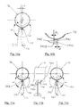
Figures 9 : Vues techniques des couteaux (9a) ou fléaux de tonte (9b). -
Figures 10 : Vue partielle de l'organe actif (10a) et de la mise en place des couteaux ou fléaux de tonte (10b) sur l'organe actif. -
Figures 11 : Vues techniques partielles de l'organe actif (11a, 11b, 11c).
-
Figure 1 : Schematic view of the machine in displacement mode. -
Figure 2 : Schematic view of the machine in working mode with positive slope s> 0. -
Figure 3 : Schematic view of the machine in working mode without unevenness s = 0. -
Figure 4 : Schematic view of the machine in working mode with negative slope s <0. -
Figure 5 : Ground support device in working mode. -
Figure 6 : Ground support device in displacement mode. -
Figure 7 : Technical views of stitched assemblies. -
Figures 8 : Active organ as a whole rotating (8a) and stopped (8b). -
Figures 9 : Technical views of knives (9a) or mowing flails (9b). -
Figures 10 : Partial view of the active organ (10a) and the placement of knives or mowing flails (10b) on the active organ. -
Figures 11 : Partial technical views of the active organ (11a, 11b, 11c).
En référence aux dessins, on peut voir, une machine automotrice qui comporte un châssis 1 monté sur un essieu avant 2 et un essieu arrière 3 , portant à l'avant un bloc moteur 4 et un poste de pilotage 5 , et à l'arrière, un dispositif de collecte des déchets 6.With reference to the drawings, it is possible to see a self-propelled machine which comprises a
Une unité de travail mobile 70 située dans l'empattement du véhicule, comprend un organe actif 71 formé principalement par un rotor 72 ayant un axe horizontal parallèle au plan formé par le sol et transversal au sens d'avancement du véhicule 8 , motorisé et muni, sensiblement sur toute la largeur de l'unité de travail 70, de couteaux ou fléaux 73 de tonte, ventilés et articulés, et de dispositifs d'accroche desdits couteaux ou fléaux 74.A mobile working
Le véhicule 8 présente deux modes de fonctionnement, un mode de travail pour lequel l'unité de travail 70 est en appui au sol et un mode déplacement pour lequel ladite unité de travail 70 se trouve en position rétractée afin de garantir une garde au sol maximale H.The
En mode travail, l'entraînement de l'organe actif 71 dans le sens de rotation 75 autorise la tonte et/ou le ramassage des déchets, et projette directement, sans aucun organe intermédiaire, les produits coupés et/ou ramassés vers le dispositif de collecte des déchets 60 .In working mode, the driving of the
En mode travail, la périphérie des couteaux ou fléaux de l'organe actif 71 détermine une ligne fonctionnelle 76 de coupe et/ou ramassage à l'aplomb de l'axe du rotor 72 dont la hauteur, dite hauteur de travail h , est obtenue au moyen d'un dispositif flottant de suivi de terrain, rétractable et réglable, défini dans son ensemble par la référence 40 .In working mode, the periphery of the knives or flails of the
L'unité de travail 70 comporte un canal d'éjection 77 dans sa partie supérieure. Ce canal d'éjection 77 présente une enveloppe formée particulièrement d'une tôle déflectrice 78 , coplanaire à un plan tangent à la périphérie des couteaux ou fléaux de l'organe actif 71 dont l'inclinaison détermine une direction optimale référencée d. L'inclinaison favorise l'éjection des déchets au regard de l'équilibre nécessaire entre les pressions d'aspiration, et, les pressions de refoulement entre les sections d'entrée et de sortie de l'unité de travail 70, à l'instar d'une turbine à palles. Elle favorise aussi la surface de contact la plus restrictive possible de la tôle déflectrice 78 propre à l'adhérence des déchets.The working
Les dimensions fonctionnelles de l'unité de travail 70 et de son canal d'éjection 77 occupent un encombrement identique et maximum sur la largeur du véhicule 8 afin d'éviter toute singularité dans le transfert des déchets.The functional dimensions of the working
La mobilité de l'unité de travail 70 est assurée au moyen d'un dispositif flottant de suivi de terrain 40 comportant un dispositif oscillant rétractable et un dispositif réglable et rétractable d'appui au sol, définie respectivement dans leurs ensembles par les références 41 et 42.The mobility of the working
Le dispositif oscillant rétractable 41 garantit une cinématique de type parallélogramme, conférant à l'unité de travail 70 un mouvement de translation coplanaire au sol entre une position de travail dans laquelle ladite unité de travail est appliquée sur une surface à entretenir, et, une position de repos dans laquelle l'unité de travail 70 est maintenue distante de cette surface. Ce mouvement de translation permet d'obtenir en mode déplacement une mise en sécurité de l'unité de travail 70 pour faciliter le franchissement des trottoirs et bordures, par exemple, lors du passage du véhicule 8 des espaces verts aux petites voiries attenantes, et d'éviter tous risques éventuels de dégradation.The retractable
La translation coplanaire permet de garder quelle que soit la hauteur de travail h l'orientation du canal d'éjection 77 selon la direction optimale de projection d.The coplanar translation makes it possible to keep whatever the working height at the orientation of the
Le dispositif oscillant rétractable 41 est principalement composé par deux bras mécaniques inférieur 411 et supérieur 412 de longueurs égales, parallèles, implantés respectivement à leurs extrémités au châssis 1 et à l'unité de travail 70. L'implantation sur le châssis 1 est réalisée au moyen de quatre liaisons de type pivot dont celle référencé 4125. Ces deux bras 411 et 412 sont totalement non contraints mécaniquement en mode travail, hormis par les degrés de liberté non offerts par des liaisons de ce type, offrant une flottabilité de l'unité de travail 70 pour un suivi de terrain et une position optimale de la ligne fonctionnelle 76 de coupe et/ou de ramassage, évitant scalpage et oublis, selon une hauteur de travail h préalablement définie par le dispositif d'appui au sol 42, en compensant les dénivellations éventuelles du sol par rapport au plan formé par les essieux.The retractable
Le débattement angulaire des bras 411 412 et l'implantation des quatre liaisons de type pivot, selon un choix de conception, permettent une course de l'unité de travail 70 autorisant un suivi de terrain négatif, et également la mise en sécurité de ladite unité 70, selon une trajectoire quasi-rectiligne parallèle à la direction de projection d limitant l'amplitude des déplacements longitudinaux de ladite unité 70 selon le sens d'avancement du véhicule 8 et par là même les volumes de jeux fonctionnels nécessaires au déplacement de ladite unité 70 et de son canal d'éjection 77 au sein d'autres ensembles constitutifs de la machine, tels la goulotte d'acheminement 13 ou du bac de ramassage 60 .The angular movement of the
Ces volumes de jeux fonctionnels restreignent les espaces par lesquels un éventuel refoulement de bac de ramassage 60 pourrait circuler.These volumes of functional games restrict the spaces by which a possible backflow of
L'unité de travail 70 traînée au regard de sa liaison mobile avec le châssis 1 située à l'avant du véhicule 8, et, sa liberté de déplacement en mode travail autorisent l'escamotage de ladite unité 70 en présence d'obstacles importants.The working
Le dispositif oscillant 41 assure le relevage de l'unité de travail 70 en ce qu'il comporte un vérin 413 de relevage simple et une pièce de renvoi 414 articulée par la liaison de type pivot 4125 et un appui linéique 4145 sur bras mécanique supérieur 412.The
En mode déplacement, l'activation du vérin simple 413 génère la sortie de la tige et la rotation de la pièce de renvoi 414 autour de son pivot 4125. L'appui linéique 4145 exerce un couple sur le bras supérieur 412, l'entraînant en rotation autour de cette même liaison pivot 4125, forçant l'unité de travail 70 à se relever. En mode déplacement, la chambre du vérin 413 n'est plus alimentée en huile, la course du vérin 413 est libre, les efforts et couples de la liaison linéique 4145 étant nuls, seuls le poids de l'unité de travail 70 et la résultante au sol de son dispositif d'appui 42 régissent l'unité de travail 70 sur la composante verticale. Ce désaccouplement du bras 412 concours à la liberté de déplacement de l'unité de travail 70 selon les dénivellations du terrain.In displacement mode, the activation of the
Le dispositif flottant de suivi de terrain 40 de l'unité de travail 70 est complété par un dispositif d'appui au sol 42 , compact, réglable et rétractable, définissant la hauteur de travail h de l'organe actif 71 .The floating
Le dispositif d'appui au sol 42 est caractérisé en ce qu'il comporte un rouleau palpeur 421 monté au moyen de paliers à deux sabots 422-1 422-2 fixés à l'unité de travail 70 par deux liaisons pivots 4225. Lesdits sabots 422-1, 422-2 sont liés à des renvois d'angle 423-1, 423-2 à l'aide des tringles 424-1, 424-2 munies à leurs extrémités de rotules, lesdits renvois d'angles 423-1, 423-2 étant eux-mêmes liés à des assemblages brochés désignés dans leurs ensembles par les références 426-1 426-2 dotés de rotules à leurs extrémités et agissant comme des barres de longueurs fixes.The
Le réglage de la hauteur du rouleau palpeur 421 par rapport à la ligne fonctionnelle 76 de coupe et/ou de ramassages s'effectue au moyen de l'allongement ou, inversement, du raccourcissement des deux assemblages brochés 426-1 426-2 . Lesdits assemblages brochés 426-1, 426-2 sont constitués respectivement d'une tige creuse 427 et d'une tige pleine 428, percées chacune de plusieurs trous, et pouvant glisser l'une dans l'autre. L'alignement et la combinaison des différents orifices et l'insertion d'une goupille mécanique 429 offrent une plage de multiples hauteurs de travail, le brochage mécanique permettant ainsi un réglage mécanique, rapide d'exécution, indéréglable dans le temps pour une homogénéité optimale du travail.The adjustment of the height of the
Le raccourcissement des assemblages brochés 426-1, 426-2 engendre les rotations des renvois d'angles 423-1 423-2 et des sabots 422-1 422-2 , et la remontée consécutive du rouleau palpeur 421 dans une trajectoire circulaire c autour des pivots 4225. À l'inverse, l'allongement desdits assemblages brochés 426-1, 426-2 génère la rotation inverse des renvois d'angles 423-1 423-2 et des sabots 422-1 422-2 , rapprochant le rouleau palpeur 421 de la ligne fonctionnelle 76 sous l'unité de travail 70 selon la trajectoire circulaire c. Dans cette position, le rouleau palpeur 421 définit un plan de travail très court entre sa ligne d'appui au sol et la ligne fonctionnelle 76 permettant à l'organe actif 71 d'anticiper de brusques dénivellations et les scalpages sur des terrains localement accidentés.The shortening of the stitched assemblies 426-1, 426-2 causes the rotations of the angle references 423-1 423-2 and the shoes 422-1 422-2, and the subsequent raising of the
Le dispositif d'appui au sol 42 est rétractable en ce qu'il comporte un vérin hydraulique double corps 425 dont les tiges, selon qu'elles soient activées ou désactivées apportent une mise en mouvement supplémentaire du rouleau palpeur 421 le long de la trajectoire circulaire c.The
En mode déplacement, le retour des tiges dans le corps du double vérin 425 et les rotations supplémentaires des renvois d'angles 423-1 423-2 et des sabots 422-1 422-2 , génère une remontée plus conséquente du rouleau palpeur 421 contribuant à la mise en sécurité de l'unité de travail 70 dans son ensemble, en préservant une garde au sol importante. Inversement, en mode travail, la sortie des tiges en butée de corps du vérin 425 replace le rouleau palpeur 421 dans une position définie par le brochage mécanique.In displacement mode, the return of the rods in the body of the
Le rouleau palpeur 421 par son appui au sol et le poids de l'unité de travail 70 concourent au ré-appuyage ou ré-enracinement des stolons à la surface du sol, limitant, ainsi le décollement dudit système racinaire occasionné par le phénomène d'aspiration de tout système de coupe, et contribuant ainsi à la formation de nouveaux pieds par marcottage naturel. Ce dispositif d'appui au sol 42 par rouleau palpeur 421 présente l'avantage de rouler le gazon sur toute la largeur de travail et d'améliorer le tallage des graminées de manière uniforme.The
Le dispositif d'appui au sol, comporte également pour une utilisation de la machine sur des surfaces plus dures, une roulette d'appui ou de voirie 431 pouvant se régler verticalement au moyen d'un filet,/taraud sur une chape intermédiaire 432 pour le réglage de la hauteur de travail. Ladite roulette d'appui 431 est orientable autour d'une liaison pivot sur l'unité de travail 70. Ladite roulette d'appui 431 est également associée à un vérin 433 permettant l'activation et la rétractation dudit dispositif 42.The ground support device also comprises for use of the machine on harder surfaces, a support wheel or
Le rouleau palpeur 421 et la roulette d'appui 431, sont activables et rétractables 1 au moyen d'un jeu approprié de cartouches hydrauliques, permettant de passer instantanément à l'entretien d'une surface souple à une surface dure.The
Pour une gestion optimale de l'interaction sol/végétaux/machine, l'unité de travail 70 est munie d'un déflecteur 79 qui s'étend sensiblement en aval et à hauteur de la ligne fonctionnelle de coupe 76 de l'organe actif 71, et qui présente une forme dont les surfaces s'opposent au flux rotatif permettant de limiter le phénomène de soufflerie/balayage et de créer une surpression à l'arrière du déflecteur 79, ainsi que, inversement, sensiblement à la base de ladite ligne fonctionnelle 76 de coupe et/ou de ramassage, une zone dépressionnaire concourant à un fort phénomène d'aspiration au passage des couteaux ou fléaux. Ce phénomène d'aspiration, relève les graminées lors de travaux de tonte, favorise la coupe par percussion, engendre une coupe régulière, et optimise la succion des déchets, quel que soient la hauteur de travail ou le revêtement du sol pratiqué.For optimum management of the soil / plant / machine interaction, the working
La zone dépressionnaire favorise le flux d'air ascensionnel généré par la vitesse de rotation de bas en haut de l'organe actif 71 et concourent, à la projection des déchets tondus et/ou ramassés au sein de l'unité de travail 70 .The low-pressure zone favors the flow of upward air generated by the rotation speed from bottom to top of the
Pour pallier les problématiques susmentionnées pour l'accrochage sans outillage des fléaux de tonte, le dispositif d'accroche 74 de l'organe actif 7L comporte un rotor à fléaux 72 sur lequel est soudé de façon multiple un élément support 741 de forme globalement cylindrique. Dans lequel est inséré une manille 742. Ledit support de manille 741 présente un canal axial 7411 d'axe parallèle à celui dudit rotor à fléau 72.To overcome the aforementioned problems for the attachment without tools mowing flails, the
Ladite manille 742 présente deux portions, l'une rectiligne 7421, dont l'extrémité libre est filetée pour accueillir un écrou non représenté qui limite la translation axiale de la manille 742 mais autorise sa rotation , et l'autre courbe et formant une boucle ouverte 7422.Said
Ladite portion rectiligne 7421 étant destinée à être introduite dans ledit canal axial 7411 et conformé pour pouvoir s'y mouvoir uniquement en pivotement.Said
Avantageusement, l'extrémité libre de la portion rectiligne 7421 de la manille 742 est filetée et garnie d'un écrou qui bloque ladite manille 742 en translation axiale tout en autorisant son pivotement au sein du canal axial 7411.Advantageously, the free end of the
Selon l'invention, ladite boucle ouverte 7422 de la manille 742 présente une section d'extrémité quasi tangente à la surface de révolution externe de l'élément support 741 laissant un jeu fonctionnel minime.According to the invention, said
Selon l'invention, ledit élément support 741 présente une paroi d'épaisseur « e » non constante.According to the invention, said
De préférence , ladite paroi comporte en un secteur une épaisseur réduite localisée avantageusement à proximité du rattachement dudit élément support 741 sur le rotor 72.Preferably, said wall comprises in a sector a reduced thickness localized advantageously close to the attachment of said
Avantageusement, ladite épaisseur réduite est la conséquence d'un méplat 7415.Advantageously, said reduced thickness is the consequence of a flat 7415.
Ladite épaisseur réduite crée avec l'extrémité libre de la boucle ouverte 7422 de ladite manille 742, un espace e1 permettant le passage du fléau 73 et son accrochage à ladite boucle ouverte 7422, en passant par un trou 731 que comporte ledit fléau 73.Said reduced thickness creates with the free end of the
En d'autres termes tel qu'illustré sur les
Le méplat 7415 de l'élément support 741 de manille 742 présente une surface parallèle à un plan transversal passant par les centres du rotor 72 et de l'élément support 741. et déportée de ce plan dans le sens donné par la rotation de l'organe actif 71 d'une distance e suffisante de manière à ce que lorsque la manille 742 se trouve dans le secteur s1, le jeu fonctionnel entre l'extrémité de la manille 742 et du méplat 7415 soit légèrement supérieur à l'épaisseur du couteau ou fléau 73 .The flat 7415 of the
Lors de l'entraînement de l'organe actif 71 , l'alignement de la manille 742 et du couteau ou fléau 73, en raison de la force centrifuge exercée sur ceux-ci, empêche leurs positionnements dans le secteur s1, rendant impossible le décrochage du couteau ou fléau 73 et sécurisant ainsi la manille 742 d'un éventuel refermement en cas d'effort à caractère centripète par l'opposition de matière du support de manille 741.When driving the
Avantageusement, selon l'invention, ledit fléau 733 comporte une extrémité active de coupe opposée à son extrémité d'accroche sur ladite boucle 7422. L'extrémité d'accroche dudit fléau 73 comporte un trou 731, et est réalisée dans un fer plat.Advantageously, according to the invention, said beam 733 comprises an active end of section opposite its hook end on said
Selon l'invention, l'espace permettant l'introduction du fléau 73 entre la manille 742, plus spécifiquement la boucle ouverte 7422, et l'élément support 741, est légèrement supérieur à l'épaisseur dudit fer plat.According to the invention, the space for introducing the
Les formes du dispositif de collecte des déchets 60, plus spécifiquement du bac de ramassage 60, sont conditionnées par, d'une part, l'obtention d'un véhicule 8 offrant une vision périphérique pour l'utilisateur, avec un bac de ramassage 60 possédant une capacité deux à trois fois supérieure aux cuves des autoportées actuelles mais s'inscrivant dans la compacité des gabarits des véhicules standards, et d'autre part, pour la gestion des fortes vitesses des flux entrants au regard de son volume et l'optimisation des cycles aérauliques selon son taux de remplissage.The forms of the
Le bac de ramassage 60 s'étend sensiblement sur la partie arrière de la machine et présente un volume frontal 61 dans lequel sur sa partie inférieure se situe une section d'entrée de largeur équivalente à la largeur de travail de l'organe actif 71.The
Les déchets projetés par l'unité de travail 70 sont dirigés à l'arrière du bac de ramassage 60 au moyen de la tôle déflectrice 62 située dans la partie supérieure du volume frontal 61 . La détente du fluide en sortie du canal d'éjection 77 , l'inclinaison légèrement montante et l'adhérence relative de la paroi supérieure du bac de ramassage 60 au regard de l'humidité résiduelle des déchets végétaux, ainsi que les orifices 631 du couvercle 63 agissent comme un système de décantation/filtration en déchargeant partiellement les flux d'air des déchets les plus lourds en suspension. Ceux-ci s'accumulent à l'arrière du bac de ramassage 60 et de fins orifices 631 disposés dans le volume supérieur du couvercle 63 permettent l'extraction des couches supérieures d'air, et limitent un phénomène de surpression. Les flux non extraits engendrent des cycles turbulents à l'intérieur du bac de ramassage 60, et compriment, les déchets par accumulation, strates après strates. Afin de limiter les phénomènes importants de turbulences, présents surtout dans les premiers moments du remplissage, l'enveloppe inférieure du bac de ramassage 60 présente des singularités pour briser la circulation de ces flux, évitant la création d'un mur d'air, créant aussi des zones tourbillonnaires à pressions relatives positives et négatives de part et d'autre des singularités. Ces décrochements de parois évitent également, lors de conditions climatiques sèches, le charriage des strates les plus récemment déposées par ces flux turbulents vers le cycle principal, mais aussi vers des zones mortes, et limitent les refoulements entre la section d'entrée du bac de ramassage 60 et la face arrière du canal d'éjection 77. Au fur et à mesure de l'accumulation, le flux primaire en provenance du canal d'éjection 77 prend le pas sur les cycles turbulents, permettant un remplissage intégral du bac de ramassage 60, hors passage du flux primaire, et déclenchant un capteur de remplissage, non présenté dans la présente invention.The waste projected by the working
Les couches supérieures d'air évacuées par les orifices 631 supérieures et latérales pouvant être chargées, selon les conditions climatiques, de fines particules de déchets végétaux et/ou de poussières, la présence d'une casquette 64 agissant comme un déflecteur, canalise le refoulement d'air en sortie du système bac 60/couvercle 63 et l'achemine vers le sol à l'arrière du véhicule 8, afin de travailler dans un environnement propre.The upper layers of air evacuated via the upper and
En position travail, le canal d'éjection 77 de l'unité de travail 70 se meut selon la trajectoire d à l'intérieur du volume frontal 61 du bac de ramassage 60 .In the working position, the
Le canal d'éjection 77 de l'unité de travail 70 est constitué d'une enveloppe dont la tôle déflectrice supérieure 781 présente une inflexion assurant le prolongement, en mode travail, de la tôle déflectrice 78 de la partie supérieure du bac de ramassage 60 , afin d'assurer une continuité du flux d'air ascendant chargé. Ce léger pincement dans la partie supérieure du canal d'éjection 77 présente l'avantage de resserrer la section aéraulique et les filets fluides et d'accroître la vitesse de ces derniers dans la section considérée pour augmenter le phénomène d'un mur d'air ainsi créé et d'éviter tout refoulement dans la partie haute du bac de ramassage 60.The
En configuration déplacement, lorsque l'unité de travail 70 est rétractée, la bouche de sortie du canal d'éjection 77 et la tôle déflectrice 62 du bac de ramassage 60 présente un jeu minimal, afin d'obtenir une hauteur d'éjection la plus grande possible dudit canal 77 et assurer, en mode travail, un rendement maximal de remplissage du bac de ramassage 60 et un débattement aussi important que possible de l'unité de travail 70 dans le cadre du suivi de terrain de ce dernier.In the displacement configuration, when the working
L'unité de travail 70 et son canal d'éjection 77 se meuvent à l'intérieur d'une goulotte d'acheminement 13 fixée au châssis 1 composée principalement d'un joint 131 dans sa partie supérieure dans le plan de jonction avec le bac de ramassage 60 lorsque celui-ci est, en appui sur le châssis 1. La goulotte 13 a pour fonction d'assurer l'étanchéité entre l'unité de travail 70 et le bac 60 fixe dans une configuration travail dans la zone à proximité de l'opérateur. La goulotte 13 canalise les éventuels refoulements ou excédents de déchets et/ou poussières en provenance du bac 60 à l'arrière de l'unité de travail 70.The working
Scindé en deux volumes distincts par l'unité de travail 70, le véhicule 8 comporte un châssis 1 élémentaire composé deux longerons parallèles à la direction d'avancement, encadrant l'unité de travail 70 et définissant la largeur hors-tout de la machine, reliés par des traverses. Lesdits longerons joignant les parties avant et arrière du véhicule 8. Leurs profils en U apportent la rigidité nécessaire pour pallier aux contraintes mécaniques telles les flexions au regard des charges supportées ou des efforts renvoyés tels ceux exercés par les montants du dispositif d'élévation du bac de ramassage 60, les torsions au regard de l'irrégularité des terrains pratiqués, les vibrations des diverses éléments en rotation Ces profils en U autorisent l'intégration des lignes de flux électriques et hydrauliques alimentant l'arrière du véhicule 8 ainsi que des articulations mécaniques telle la liaison mobile entre le châssis 1 et l'unité de travail 70.Separated into two separate volumes by the working
Claims (6)
Applications Claiming Priority (1)
| Application Number | Priority Date | Filing Date | Title |
|---|---|---|---|
| FR1458878A FR3025972A1 (en) | 2014-09-19 | 2014-09-19 | AUTOMOTIVE MACHINE FOR MILLING AND / OR COLLECTING FOR THE MAINTENANCE OF GREEN SPACES |
Publications (2)
| Publication Number | Publication Date |
|---|---|
| EP2997809A1 true EP2997809A1 (en) | 2016-03-23 |
| EP2997809B1 EP2997809B1 (en) | 2017-11-22 |
Family
ID=54478853
Family Applications (1)
| Application Number | Title | Priority Date | Filing Date |
|---|---|---|---|
| EP15306459.7A Active EP2997809B1 (en) | 2014-09-19 | 2015-09-18 | Device for coupling a flail knife |
Country Status (2)
| Country | Link |
|---|---|
| EP (1) | EP2997809B1 (en) |
| FR (3) | FR3025972A1 (en) |
Cited By (2)
| Publication number | Priority date | Publication date | Assignee | Title |
|---|---|---|---|---|
| FR3055510A1 (en) * | 2016-09-08 | 2018-03-09 | F.M. Sa Forges Des Margerides | VEHICLE AUTOPORTE FOR CUTTING AND GRINDING PLANTS |
| US20210127577A1 (en) * | 2019-11-04 | 2021-05-06 | Ricky A. Weihl | Mower assembly |
Families Citing this family (1)
| Publication number | Priority date | Publication date | Assignee | Title |
|---|---|---|---|---|
| CN107318355A (en) * | 2017-02-20 | 2017-11-07 | 佛山尘凡环保科技有限公司 | A kind of gardens lawn pruning |
Citations (4)
| Publication number | Priority date | Publication date | Assignee | Title |
|---|---|---|---|---|
| FR1422000A (en) | 1965-01-25 | 1965-12-17 | Edward Thomas & Co Oswestry Lt | Advanced Lawn Mower |
| US3831359A (en) * | 1973-07-30 | 1974-08-27 | B Mathews | Blade assembly for flail mower |
| DE8704846U1 (en) * | 1986-04-05 | 1987-06-25 | Amazonen-Werke H. Dreyer Gmbh & Co Kg, 4507 Hasbergen, De | |
| DE19607350A1 (en) | 1996-02-27 | 1997-08-28 | Amazone Machines Agricoles Sa | Mowing machine |
Family Cites Families (9)
| Publication number | Priority date | Publication date | Assignee | Title |
|---|---|---|---|---|
| US2670486A (en) * | 1950-08-04 | 1954-03-02 | Edward A Bodine | Rotary brush construction and mounting therefor |
| US3546951A (en) * | 1965-10-24 | 1970-12-15 | Carl Van Ausdall | Transmission |
| US4260027A (en) * | 1978-04-17 | 1981-04-07 | W.E.F.C.O., Inc. | Flail-type mulcher cultivator |
| US4903469A (en) * | 1986-10-21 | 1990-02-27 | Kubota, Ltd. | Lawn mower |
| US6003186A (en) * | 1997-02-18 | 1999-12-21 | Tennant Company | Cylindrical brush for a sweeping machine |
| US7287363B2 (en) * | 2004-04-20 | 2007-10-30 | Deere & Company | Riding mower having multiple cutting units |
| DE102006034436A1 (en) * | 2006-07-26 | 2008-01-31 | Amazonen-Werke H. Dreyer Gmbh & Co. Kg | Mobile collecting machine e.g. mowing device, has collecting bag removably attached to collecting frame, and collector hung with rolled periphery region over circular region of collecting frame |
| US7637090B2 (en) * | 2007-10-17 | 2009-12-29 | Deere & Company | Roller configuration having reduced overlap for a grass mowing machine |
| US8099936B2 (en) * | 2009-01-27 | 2012-01-24 | Textron Innovations Inc. | Electrically powered flail mower |
-
2014
- 2014-09-19 FR FR1458878A patent/FR3025972A1/en active Pending
-
2015
- 2015-09-18 FR FR1558798A patent/FR3025973B1/en active Active
- 2015-09-18 FR FR1558799A patent/FR3025971B1/en active Active
- 2015-09-18 EP EP15306459.7A patent/EP2997809B1/en active Active
Patent Citations (4)
| Publication number | Priority date | Publication date | Assignee | Title |
|---|---|---|---|---|
| FR1422000A (en) | 1965-01-25 | 1965-12-17 | Edward Thomas & Co Oswestry Lt | Advanced Lawn Mower |
| US3831359A (en) * | 1973-07-30 | 1974-08-27 | B Mathews | Blade assembly for flail mower |
| DE8704846U1 (en) * | 1986-04-05 | 1987-06-25 | Amazonen-Werke H. Dreyer Gmbh & Co Kg, 4507 Hasbergen, De | |
| DE19607350A1 (en) | 1996-02-27 | 1997-08-28 | Amazone Machines Agricoles Sa | Mowing machine |
Cited By (2)
| Publication number | Priority date | Publication date | Assignee | Title |
|---|---|---|---|---|
| FR3055510A1 (en) * | 2016-09-08 | 2018-03-09 | F.M. Sa Forges Des Margerides | VEHICLE AUTOPORTE FOR CUTTING AND GRINDING PLANTS |
| US20210127577A1 (en) * | 2019-11-04 | 2021-05-06 | Ricky A. Weihl | Mower assembly |
Also Published As
| Publication number | Publication date |
|---|---|
| FR3025971A1 (en) | 2016-03-25 |
| FR3025972A1 (en) | 2016-03-25 |
| FR3025973B1 (en) | 2017-09-01 |
| FR3025971B1 (en) | 2017-11-24 |
| EP2997809B1 (en) | 2017-11-22 |
| FR3025973A1 (en) | 2016-03-25 |
Similar Documents
| Publication | Publication Date | Title |
|---|---|---|
| BR102017015754A2 (en) | SELF ADJUSTABLE FEEDER FOR SUGAR CANE HARVESTERS | |
| EP2997809B1 (en) | Device for coupling a flail knife | |
| FR2953230A1 (en) | Frontal recuperation device for use with e.g. amphibious machine to recuperate green algae suspended in water at sea, has pressing device permitting extraction of large quantity of water and sand contained in floating material | |
| WO2012168578A1 (en) | Extractor for removing stones from soil, principally agricultural soil | |
| EP2840883A1 (en) | Method and device for hulling hemp seeds and harvester provided with such a device | |
| FR2915847A1 (en) | LAWN MOWER COMPRISING A SWIVEL GRASS MANIFOLD USING A CUTTER | |
| EP0213052B1 (en) | Mower | |
| WO2000078122A2 (en) | Device and method for treating the soil by aeration | |
| FR2516838A1 (en) | APPARATUS FOR CLEANING A SURFACE USING AN ABRASIVE MATERIAL | |
| FR3070818A3 (en) | MACHINE FOR TILLING THE FIELD | |
| EP0641157A1 (en) | Machine for the destruction of banana plantation. | |
| EP0366174B1 (en) | Machine for harvesting fruits or the like deposited on the soil | |
| US7163068B2 (en) | Hitch assembly | |
| BR112013014069B1 (en) | beach cleaner | |
| EP0304101A1 (en) | Method and device for gathering products, especially fruit, from the ground | |
| BE896006A (en) | PROCESS FOR THE PERMANENT IMPROVEMENT OF THE SURFACE DRAINAGE OF LANDS, PREFERABLY, GROUNDS COVERED WITH GRASS, AND APPARATUS FOR CARRYING OUT SAID METHOD | |
| FR2685993A1 (en) | Machine for cutting plants, particularly forestry shredder | |
| FR2658981A1 (en) | APPARATUS FOR COLLECTING LAWN FROM DEAD LEAVES AND OTHER SOIL SOIL. | |
| CN206323750U (en) | Roller type brush incomplete film-recovering machine | |
| FR2771894A1 (en) | System for cutting or reaping vegetation especially on edges of roads | |
| EP1175942A1 (en) | Mobile shredder for shredding refuse spread on the ground | |
| EP3628780B1 (en) | Vehicle for the preparation of ski pists with a snow removal equipment | |
| FR2748630A1 (en) | Animal feed bale separator | |
| FR3052957A1 (en) | TOWING ELEMENT FOR BREAD HARVESTERS | |
| FR2840331A1 (en) | Device for spreading ballast on roadway comprises mobile chassis supporting tipping skip containing ballast, buffer tray inserted between skip outlet and ballast distribution means |
Legal Events
| Date | Code | Title | Description |
|---|---|---|---|
| PUAI | Public reference made under article 153(3) epc to a published international application that has entered the european phase |
Free format text: ORIGINAL CODE: 0009012 |
|
| AK | Designated contracting states |
Kind code of ref document: A1 Designated state(s): AL AT BE BG CH CY CZ DE DK EE ES FI FR GB GR HR HU IE IS IT LI LT LU LV MC MK MT NL NO PL PT RO RS SE SI SK SM TR |
|
| AX | Request for extension of the european patent |
Extension state: BA ME |
|
| 17P | Request for examination filed |
Effective date: 20160906 |
|
| RBV | Designated contracting states (corrected) |
Designated state(s): AL AT BE BG CH CY CZ DE DK EE ES FI FR GB GR HR HU IE IS IT LI LT LU LV MC MK MT NL NO PL PT RO RS SE SI SK SM TR |
|
| GRAP | Despatch of communication of intention to grant a patent |
Free format text: ORIGINAL CODE: EPIDOSNIGR1 |
|
| INTG | Intention to grant announced |
Effective date: 20170308 |
|
| GRAJ | Information related to disapproval of communication of intention to grant by the applicant or resumption of examination proceedings by the epo deleted |
Free format text: ORIGINAL CODE: EPIDOSDIGR1 |
|
| INTC | Intention to grant announced (deleted) | ||
| GRAP | Despatch of communication of intention to grant a patent |
Free format text: ORIGINAL CODE: EPIDOSNIGR1 |
|
| INTG | Intention to grant announced |
Effective date: 20170821 |
|
| GRAS | Grant fee paid |
Free format text: ORIGINAL CODE: EPIDOSNIGR3 |
|
| GRAA | (expected) grant |
Free format text: ORIGINAL CODE: 0009210 |
|
| AK | Designated contracting states |
Kind code of ref document: B1 Designated state(s): AL AT BE BG CH CY CZ DE DK EE ES FI FR GB GR HR HU IE IS IT LI LT LU LV MC MK MT NL NO PL PT RO RS SE SI SK SM TR |
|
| REG | Reference to a national code |
Ref country code: GB Ref legal event code: FG4D Free format text: NOT ENGLISH |
|
| REG | Reference to a national code |
Ref country code: CH Ref legal event code: EP |
|
| REG | Reference to a national code |
Ref country code: IE Ref legal event code: FG4D Free format text: LANGUAGE OF EP DOCUMENT: FRENCH |
|
| REG | Reference to a national code |
Ref country code: AT Ref legal event code: REF Ref document number: 947499 Country of ref document: AT Kind code of ref document: T Effective date: 20171215 |
|
| REG | Reference to a national code |
Ref country code: DE Ref legal event code: R096 Ref document number: 602015006179 Country of ref document: DE |
|
| REG | Reference to a national code |
Ref country code: NL Ref legal event code: MP Effective date: 20171122 |
|
| REG | Reference to a national code |
Ref country code: LT Ref legal event code: MG4D |
|
| REG | Reference to a national code |
Ref country code: AT Ref legal event code: MK05 Ref document number: 947499 Country of ref document: AT Kind code of ref document: T Effective date: 20171122 |
|
| PG25 | Lapsed in a contracting state [announced via postgrant information from national office to epo] |
Ref country code: ES Free format text: LAPSE BECAUSE OF FAILURE TO SUBMIT A TRANSLATION OF THE DESCRIPTION OR TO PAY THE FEE WITHIN THE PRESCRIBED TIME-LIMIT Effective date: 20171122 Ref country code: NO Free format text: LAPSE BECAUSE OF FAILURE TO SUBMIT A TRANSLATION OF THE DESCRIPTION OR TO PAY THE FEE WITHIN THE PRESCRIBED TIME-LIMIT Effective date: 20180222 Ref country code: LT Free format text: LAPSE BECAUSE OF FAILURE TO SUBMIT A TRANSLATION OF THE DESCRIPTION OR TO PAY THE FEE WITHIN THE PRESCRIBED TIME-LIMIT Effective date: 20171122 Ref country code: SE Free format text: LAPSE BECAUSE OF FAILURE TO SUBMIT A TRANSLATION OF THE DESCRIPTION OR TO PAY THE FEE WITHIN THE PRESCRIBED TIME-LIMIT Effective date: 20171122 Ref country code: FI Free format text: LAPSE BECAUSE OF FAILURE TO SUBMIT A TRANSLATION OF THE DESCRIPTION OR TO PAY THE FEE WITHIN THE PRESCRIBED TIME-LIMIT Effective date: 20171122 Ref country code: NL Free format text: LAPSE BECAUSE OF FAILURE TO SUBMIT A TRANSLATION OF THE DESCRIPTION OR TO PAY THE FEE WITHIN THE PRESCRIBED TIME-LIMIT Effective date: 20171122 |
|
| PG25 | Lapsed in a contracting state [announced via postgrant information from national office to epo] |
Ref country code: LV Free format text: LAPSE BECAUSE OF FAILURE TO SUBMIT A TRANSLATION OF THE DESCRIPTION OR TO PAY THE FEE WITHIN THE PRESCRIBED TIME-LIMIT Effective date: 20171122 Ref country code: GR Free format text: LAPSE BECAUSE OF FAILURE TO SUBMIT A TRANSLATION OF THE DESCRIPTION OR TO PAY THE FEE WITHIN THE PRESCRIBED TIME-LIMIT Effective date: 20180223 Ref country code: AT Free format text: LAPSE BECAUSE OF FAILURE TO SUBMIT A TRANSLATION OF THE DESCRIPTION OR TO PAY THE FEE WITHIN THE PRESCRIBED TIME-LIMIT Effective date: 20171122 Ref country code: BG Free format text: LAPSE BECAUSE OF FAILURE TO SUBMIT A TRANSLATION OF THE DESCRIPTION OR TO PAY THE FEE WITHIN THE PRESCRIBED TIME-LIMIT Effective date: 20180222 Ref country code: RS Free format text: LAPSE BECAUSE OF FAILURE TO SUBMIT A TRANSLATION OF THE DESCRIPTION OR TO PAY THE FEE WITHIN THE PRESCRIBED TIME-LIMIT Effective date: 20171122 Ref country code: HR Free format text: LAPSE BECAUSE OF FAILURE TO SUBMIT A TRANSLATION OF THE DESCRIPTION OR TO PAY THE FEE WITHIN THE PRESCRIBED TIME-LIMIT Effective date: 20171122 |
|
| PG25 | Lapsed in a contracting state [announced via postgrant information from national office to epo] |
Ref country code: CZ Free format text: LAPSE BECAUSE OF FAILURE TO SUBMIT A TRANSLATION OF THE DESCRIPTION OR TO PAY THE FEE WITHIN THE PRESCRIBED TIME-LIMIT Effective date: 20171122 Ref country code: CY Free format text: LAPSE BECAUSE OF FAILURE TO SUBMIT A TRANSLATION OF THE DESCRIPTION OR TO PAY THE FEE WITHIN THE PRESCRIBED TIME-LIMIT Effective date: 20171122 Ref country code: SK Free format text: LAPSE BECAUSE OF FAILURE TO SUBMIT A TRANSLATION OF THE DESCRIPTION OR TO PAY THE FEE WITHIN THE PRESCRIBED TIME-LIMIT Effective date: 20171122 Ref country code: EE Free format text: LAPSE BECAUSE OF FAILURE TO SUBMIT A TRANSLATION OF THE DESCRIPTION OR TO PAY THE FEE WITHIN THE PRESCRIBED TIME-LIMIT Effective date: 20171122 Ref country code: DK Free format text: LAPSE BECAUSE OF FAILURE TO SUBMIT A TRANSLATION OF THE DESCRIPTION OR TO PAY THE FEE WITHIN THE PRESCRIBED TIME-LIMIT Effective date: 20171122 |
|
| REG | Reference to a national code |
Ref country code: DE Ref legal event code: R097 Ref document number: 602015006179 Country of ref document: DE |
|
| PG25 | Lapsed in a contracting state [announced via postgrant information from national office to epo] |
Ref country code: RO Free format text: LAPSE BECAUSE OF FAILURE TO SUBMIT A TRANSLATION OF THE DESCRIPTION OR TO PAY THE FEE WITHIN THE PRESCRIBED TIME-LIMIT Effective date: 20171122 Ref country code: PL Free format text: LAPSE BECAUSE OF FAILURE TO SUBMIT A TRANSLATION OF THE DESCRIPTION OR TO PAY THE FEE WITHIN THE PRESCRIBED TIME-LIMIT Effective date: 20171122 Ref country code: SM Free format text: LAPSE BECAUSE OF FAILURE TO SUBMIT A TRANSLATION OF THE DESCRIPTION OR TO PAY THE FEE WITHIN THE PRESCRIBED TIME-LIMIT Effective date: 20171122 Ref country code: IT Free format text: LAPSE BECAUSE OF FAILURE TO SUBMIT A TRANSLATION OF THE DESCRIPTION OR TO PAY THE FEE WITHIN THE PRESCRIBED TIME-LIMIT Effective date: 20171122 |
|
| REG | Reference to a national code |
Ref country code: FR Ref legal event code: PLFP Year of fee payment: 4 |
|
| PG25 | Lapsed in a contracting state [announced via postgrant information from national office to epo] |
Ref country code: MT Free format text: LAPSE BECAUSE OF FAILURE TO SUBMIT A TRANSLATION OF THE DESCRIPTION OR TO PAY THE FEE WITHIN THE PRESCRIBED TIME-LIMIT Effective date: 20171122 |
|
| PLBE | No opposition filed within time limit |
Free format text: ORIGINAL CODE: 0009261 |
|
| STAA | Information on the status of an ep patent application or granted ep patent |
Free format text: STATUS: NO OPPOSITION FILED WITHIN TIME LIMIT |
|
| 26N | No opposition filed |
Effective date: 20180823 |
|
| PG25 | Lapsed in a contracting state [announced via postgrant information from national office to epo] |
Ref country code: SI Free format text: LAPSE BECAUSE OF FAILURE TO SUBMIT A TRANSLATION OF THE DESCRIPTION OR TO PAY THE FEE WITHIN THE PRESCRIBED TIME-LIMIT Effective date: 20171122 |
|
| PG25 | Lapsed in a contracting state [announced via postgrant information from national office to epo] |
Ref country code: MC Free format text: LAPSE BECAUSE OF FAILURE TO SUBMIT A TRANSLATION OF THE DESCRIPTION OR TO PAY THE FEE WITHIN THE PRESCRIBED TIME-LIMIT Effective date: 20171122 |
|
| REG | Reference to a national code |
Ref country code: CH Ref legal event code: PL |
|
| REG | Reference to a national code |
Ref country code: BE Ref legal event code: MM Effective date: 20180930 |
|
| REG | Reference to a national code |
Ref country code: IE Ref legal event code: MM4A |
|
| PG25 | Lapsed in a contracting state [announced via postgrant information from national office to epo] |
Ref country code: LU Free format text: LAPSE BECAUSE OF NON-PAYMENT OF DUE FEES Effective date: 20180918 |
|
| PG25 | Lapsed in a contracting state [announced via postgrant information from national office to epo] |
Ref country code: IE Free format text: LAPSE BECAUSE OF NON-PAYMENT OF DUE FEES Effective date: 20180918 |
|
| PG25 | Lapsed in a contracting state [announced via postgrant information from national office to epo] |
Ref country code: BE Free format text: LAPSE BECAUSE OF NON-PAYMENT OF DUE FEES Effective date: 20180930 Ref country code: CH Free format text: LAPSE BECAUSE OF NON-PAYMENT OF DUE FEES Effective date: 20180930 Ref country code: LI Free format text: LAPSE BECAUSE OF NON-PAYMENT OF DUE FEES Effective date: 20180930 |
|
| PG25 | Lapsed in a contracting state [announced via postgrant information from national office to epo] |
Ref country code: TR Free format text: LAPSE BECAUSE OF FAILURE TO SUBMIT A TRANSLATION OF THE DESCRIPTION OR TO PAY THE FEE WITHIN THE PRESCRIBED TIME-LIMIT Effective date: 20171122 |
|
| PG25 | Lapsed in a contracting state [announced via postgrant information from national office to epo] |
Ref country code: PT Free format text: LAPSE BECAUSE OF FAILURE TO SUBMIT A TRANSLATION OF THE DESCRIPTION OR TO PAY THE FEE WITHIN THE PRESCRIBED TIME-LIMIT Effective date: 20171122 |
|
| PG25 | Lapsed in a contracting state [announced via postgrant information from national office to epo] |
Ref country code: MK Free format text: LAPSE BECAUSE OF NON-PAYMENT OF DUE FEES Effective date: 20171122 Ref country code: HU Free format text: LAPSE BECAUSE OF FAILURE TO SUBMIT A TRANSLATION OF THE DESCRIPTION OR TO PAY THE FEE WITHIN THE PRESCRIBED TIME-LIMIT; INVALID AB INITIO Effective date: 20150918 |
|
| PG25 | Lapsed in a contracting state [announced via postgrant information from national office to epo] |
Ref country code: AL Free format text: LAPSE BECAUSE OF FAILURE TO SUBMIT A TRANSLATION OF THE DESCRIPTION OR TO PAY THE FEE WITHIN THE PRESCRIBED TIME-LIMIT Effective date: 20171122 Ref country code: IS Free format text: LAPSE BECAUSE OF FAILURE TO SUBMIT A TRANSLATION OF THE DESCRIPTION OR TO PAY THE FEE WITHIN THE PRESCRIBED TIME-LIMIT Effective date: 20180322 |
|
| GBPC | Gb: european patent ceased through non-payment of renewal fee |
Effective date: 20190918 |
|
| PG25 | Lapsed in a contracting state [announced via postgrant information from national office to epo] |
Ref country code: GB Free format text: LAPSE BECAUSE OF NON-PAYMENT OF DUE FEES Effective date: 20190918 |
|
| PGFP | Annual fee paid to national office [announced via postgrant information from national office to epo] |
Ref country code: FR Payment date: 20220915 Year of fee payment: 8 |
|
| PGFP | Annual fee paid to national office [announced via postgrant information from national office to epo] |
Ref country code: DE Payment date: 20221014 Year of fee payment: 8 |