EP2997428B1 - Roboterpositionierung - Google Patents
Roboterpositionierung Download PDFInfo
- Publication number
- EP2997428B1 EP2997428B1 EP14734303.2A EP14734303A EP2997428B1 EP 2997428 B1 EP2997428 B1 EP 2997428B1 EP 14734303 A EP14734303 A EP 14734303A EP 2997428 B1 EP2997428 B1 EP 2997428B1
- Authority
- EP
- European Patent Office
- Prior art keywords
- robot
- joint positions
- goal
- calibration
- location
- Prior art date
- Legal status (The legal status is an assumption and is not a legal conclusion. Google has not performed a legal analysis and makes no representation as to the accuracy of the status listed.)
- Active
Links
Images


Classifications
-
- B—PERFORMING OPERATIONS; TRANSPORTING
- B25—HAND TOOLS; PORTABLE POWER-DRIVEN TOOLS; MANIPULATORS
- B25J—MANIPULATORS; CHAMBERS PROVIDED WITH MANIPULATION DEVICES
- B25J9/00—Program-controlled manipulators
- B25J9/16—Program controls
- B25J9/1679—Program controls characterised by the tasks executed
- B25J9/1692—Calibration of manipulator
-
- G—PHYSICS
- G05—CONTROLLING; REGULATING
- G05B—CONTROL OR REGULATING SYSTEMS IN GENERAL; FUNCTIONAL ELEMENTS OF SUCH SYSTEMS; MONITORING OR TESTING ARRANGEMENTS FOR SUCH SYSTEMS OR ELEMENTS
- G05B2219/00—Program-control systems
- G05B2219/30—Nc systems
- G05B2219/39—Robotics, robotics to robotics hand
- G05B2219/39019—Calibration by cmm coordinate measuring machine over a certain volume
-
- G—PHYSICS
- G05—CONTROLLING; REGULATING
- G05B—CONTROL OR REGULATING SYSTEMS IN GENERAL; FUNCTIONAL ELEMENTS OF SUCH SYSTEMS; MONITORING OR TESTING ARRANGEMENTS FOR SUCH SYSTEMS OR ELEMENTS
- G05B2219/00—Program-control systems
- G05B2219/30—Nc systems
- G05B2219/39—Robotics, robotics to robotics hand
- G05B2219/39031—Use of model for robot and for measuring device
Definitions
- the invention relates to robot positioning devices, systems, and methods.
- Conventional robots may follow instructions to move an instrument of the robot to a goal location, or a series of goal locations in the process of performing a task.
- robots are installed in a particular operating environment to perform a task and the joint positions necessary to perform the task are taught to the robot manually.
- the robot then moves through the learned joint positions.
- calibrating the robot may not be necessary, as each goal location of the robot and/or the robot's instruments may be set manually and may simply be correlated with a set of joint positions measured by the robot.
- the movement of the robot may be programed, often using computer aided design (CAD) and/or computer aided manufacture (CAM), to perform tasks without manually teaching the robot each goal location.
- Programing the robot using CAD/CAM and the like may be generally described herein as programing offline.
- the robot may execute the movement based on a kinematic model of the robot.
- the kinematic model may associate joint positions of the robot with locations of the robot, and more particularly, with locations of an instrument of the robot.
- a program may provide the robot with a goal location.
- the robot may access a native kinematic model to determine joint positions of the robot that will allow the robot to be located in the goal location.
- the kinematic model generally does not provide joint positions needed to accurately direct the robot to the goal location.
- the robot will often require manual fine-tuning to accurately perform movements for a task programed offline. However, if the robot is properly calibrated, the robot may accurately perform movements for the task without manual fine-tuning.
- a calibration process may be performed to calibrate the kinematic model such that the model accurately represents observed behavior of the robot.
- the robot may be calibrated by positioning the robot's joints in multiple calibration positions and externally measuring the location of the robot in the calibration positions. Using the joint positions and the associated location data observed during the calibration, the kinematic model may be updated to more accurately model the robot's location to the joint positions of the robot. Conventionally, few robots are calibrated.
- Calibrating a robot may allow the robot to more efficiently adapt to changing tasks. For example, implementing product changes may be streamlined by updating the robots' manufacturing tasks offline. Furthermore, robots may be used to perform an ever-changing variety of tasks without significant downtime for manual programing or manually fine-tuning programs created offline.
- Robot manufacturers may prevent the native kinematic model supplied internal to the robot to be changed/updated by the user.
- limited parameters such as link lines and twist may be changed by the user.
- not all of the parameters may be changed. Even if all of the parameters could be changed, the kinematic model itself may not be updatable to a more advanced kinematic model.
- Embodiments relate to devices, systems, and methods for positioning a robot.
- embodiments may relate to devices, systems, and methods for developing a calibrated kinematic model for a robot and providing positioning information to the robot based on the calibrated kinematic model.
- a robot positioning device for determining and providing joint positions to robots in an operation environment of the robots such that the robots will be positioned at a goal location when joints of the robots are positioned in the provided joint positions includes a first interface and a second interface.
- the first interface is configured to communicate with a first robot.
- the second interface configured to communicate with a location measuring system.
- the robot positioning device further includes a calibrator, a modeler, and an instructor.
- the calibrator is configured to direct the location measuring system via the second interface to determine multiple calibration locations of the first robot when joints of the first robot are positioned in multiple calibration joint positions.
- the modeler is configured to create a first calibrated model relating joint positions of the first robot to locations of the first robot.
- the first calibrated model is based at least in part on the multiple calibration location measurements of the first robot received from the location measuring system and associated calibration joint positions of the joints of the first robot.
- the instructor is configured to receive a first goal location from the first robot via the first interface.
- the instructor is further configured to transmit multiple goal joint positions to the first robot via the first interface, the multiple goal joint positions based at least in part on the first goal location and the first calibrated model.
- a system for directing a robot to accurate locations in an operation environment includes a robot positioning device.
- the robot positioning device includes a first interface configured to communicate with the robot, and a second interface configured to communicate with a location measuring system.
- the robot positioning device further includes a calibrator, a modeler, and an instructor.
- the calibrator is configured to direct the location measuring system via the second interface to determine multiple calibration locations of the robot when joints of the robot are positioned in multiple calibration joint positions.
- the modeler is configured to create a calibrated model relating the joint positions of the robot to the locations of the robot.
- the calibrated model is based at least in part on the multiple calibration locations of the robot received from the location measuring system and associated multiple calibration joint positions of the joints of the robot.
- the instructor is configured to receive a goal location from the robot via the first interface.
- the instructor is further configured to transmit goal joint positions to the robot via the first interface.
- the goal joint positions based at least in part on the goal location and the calibrated model.
- Embodiments disclosed relate to devices, systems, and methods for positioning a robot.
- a calibrated kinematic model may be developed for a robot.
- the robot may be instructed to assume multiple calibration positions while the robot's location is determined.
- the kinematic model may be developed based on the determined locations of the robot and the associated calibration positions.
- Positioning information may be provided to the robot based on the developed kinematic model.
- the kinematic model may be employed without altering the robot's native kinematic model.
- the robot may provide a goal location, which may be used with the kinematic model to determine a set of goal joint positions that will locate the robot in the goal location.
- the goal joint positions may be provided to the robot so the robot may alter its joint positions and move accurately to the goal location.
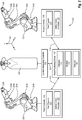
- Figure 1 is a diagrammatic view of an example robot positioning system 100.
- the system 100 may include a robot 102.
- the robot 102 may be an industrial arm-style robot 102. Alternately, embodiments may be used with other styles of robots 102.
- the robot 102 includes movable joints.
- the robot 102 may include joints 104a, 104b, 104c, 104d, and 104e (collectively "joints 104").
- Joints 104 generally describe a junction of two or more portions of the robot 102 that may be moved relative to each other.
- the portions may be configured to move relative to each other in a number of ways. For example, the portions may rotate relative to each other about an axis, may translate relative to each other, or the like.
- the word "position" is used herein to generally describe the relative placement of portions of the robot 102 relative to other portions of the robot 102.
- the robot 102 may generally control the positioning of the various portions of the robot 102 relative to each other.
- the relative positioning of the various portions of the robot 102 may be measured and tracked by the robot 102. Values may be assigned to the relative positions and are described generally herein as joint positions.
- the robot 102 may generally measure the joint positions and move the joints 104 to desired joint positions with high accuracy.
- the word "location” is used herein to generally describe the relative placement and orientation of portions of the robot 102 relative to the robot's environment.
- the robot's location may be related to environmental coordinates 128.
- the location of the robot 102 generally includes a placement and orientation of an instrument 106 relative to the robot's environment.
- the location may include translational displacement, as well as angular displacement of the instrument 106.
- the instrument 106 may include any suitable tools, including tools for painting, grasping, cutting, welding, inspecting, and the like. Often, the location of the instrument 106 is a primary concern in a program and/or task of the robot 102.
- the location of the robot 102 may be related to the positions of the joints 104. For example, when the joints 104 are positioned according to a first set of joint positions, the robot 102 may be located in a first location. When the joints 104 are positioned according to a second set of joint positions, the robot 102 may be located in a second location. The robot 102 may be located in the first and second locations by respectively positioning the joints according to the first and second set of joint positions.
- the robot 102 includes a native robot controller 108.
- the robot controller 108 generally runs via a native control language 110. Different robot 102 manufacturers may use different native control languages 110.
- the robot controller 108 may include a task program 111.
- the task program 111 may include a script of actions that the robot 102 should take to complete a task.
- the task program 111 may be programed offline and provided to the robot controller 108.
- the task program 111 may include a series of locations that the robot 102 should move to in order to complete a task.
- the task program 111 may also include a series of actions the instrument 106 should take to complete the task.
- the robot controller 108 may communicate with a robot positioning device 112 via a first interface 114.
- the interface 114 may communicate with the robot controller 108 via the native control language 110 of the robot controller 108.
- the robot controller 108 may send a goal location to the device 112 and the device 112 may return a set of goal joint positions based on a calibrated kinematic model as described herein.
- the goal location sent to the robot controller 108 may be a location identified by the task program 111.
- the device 112 may allow the robot 102 to accurately perform tasks based on calibrated kinematic models without relying on and/or calibrating a native kinematic model located on the robot controller 108.
- the device 112 may allow more customization of the kinematic model than may be allowed for the native kinematic model located on the robot controller 108.
- the device 112 may be an external device 112 located in the environment of the robot 102.
- the interface 114 may include a physical data connection such as an Ethernet connection, universal serial bus (USB) connection, or the like.
- the interface 114 may include a radio connection such as an IEEE 802.11 connection, a Bluetooth connection, or the like.
- the device 112 may be remotely located and the interface 114 may include a remote connection such as an internet connection, intranet connection, or the like.
- the device 112 includes a second interface 124 allowing the device 112 to communicate with a location measuring system including a location measuring controller 122 and a location measuring device 126.
- the location measuring device 126 includes a laser tracker.
- the device 112 may direct the location measuring controller 122 to determine the location of the robot 102.
- the location measuring controller 122 may direct the location measuring device 126 to measure the location of the robot 102.
- the location measuring device 126 may measure the location of the robot 102 via any suitable measurement technique.
- the location measuring device 126 may measure the location of the robot 102 optically via laser tracking. Determining the location of the robot 102 may generally include determining the location of the instrument 106.
- the location measuring device 126 measures three degrees of freedom of the instrument 106, e.g., translational displacement in x, y, and z coordinates.
- the location measuring device 126 may measure six degrees of freedom of the tool 106, e.g., translational displacement in x, y, and z coordinates and angular displacement in Rx, Ry, and Rz coordinates.
- the device 112 may include a calibrator 116.
- the calibrator 116 may facilitate a process of observing the locations of the robot 102 with a variety of joint positions such that a calibrated kinematic model may be created by a modeler 118.
- Calibration may include intrinsic calibration.
- the robot 102 may be calibrated relative to a base of the robot 102.
- calibration may include extrinsic calibration.
- the robot 102 may be calibrated relative to an operating environment of the robot 102. Calibration may be performed when the device 112 is first connected to the robot 102, or when requested by a user, the device 112, the location measuring controller 122 and/or the robot 102 via the robot controller 108.
- the calibrator 116 may direct the robot controller 108 to instruct the robot 102 to position the joints 104 in a variety of calibration joint positions.
- the robot controller 108 may provide the calibration joint positions to the device 112.
- calibration joint positions native to the robot 102 and/or the robot controller 108 may be used.
- the device 112 may provide the robot controller 108 with calibration joint positions.
- the calibrator 116 may also direct the location measuring controller 122 to instruct the location measuring device 126 to determine calibration locations of the robot 102 as it is positioned with the calibration joint positions.
- the calibration locations of robot 102 generally include instrument 106 calibration locations.
- the location measuring controller 122 provides the calibration locations to the device 112.
- the calibration locations may generally be associated with the calibration joint positions via time, sequence, and the like.
- the modeler 118 may create a calibrated kinematic model for the robot 102 based on the calibration joint positions and the associated calibration locations observed by the location measuring system.
- the instructor 120 may receive a goal location from the robot 102 via the interface 114.
- the goal location may be received during operation of the robot 102.
- the goal location may be provided by the task program 111 and may be one of a series of locations the task program 111 may provide for the robot 102 to perform a task.
- the instructor 120 may determine a set of goal joint positions that will allow the robot 102 to reach the goal location based on the calibrated kinematic model created by the modeler 118. In some embodiments, the instructor 120 may also receive information describing current joint positions and/or a current location of the robot 102 via the interface 114. The current joint positions and/or the current location may be considered in determining a set of goal joint positions that will allow the robot 102 to reach the goal location based on the calibrated kinematic model.
- the goal location received by the instructor 120 may include a goal instrument 106 location transformation and the current joint positions and/or a current instrument 106 location.
- the robot controller 108 may request a set of goal joint positions that will allow the robot 102 to move the instrument 106 to a goal location relative to the current location of the instrument 106.
- the robot controller 108 may request a set of goal joint positions that will move the instrument 106 to a location 50 millimeters (mm) above, 30 mm to the right, and 20 mm back from the current location of the instrument 106.
- the system 100 may be used to allow the robot 102 to accurately traverse trajectories to a goal location.
- the trajectory may be divided into a series of intermediate locations.
- the system 100 may direct the robot 102 through the intermediate locations at a suitable rate in a manner generally corresponding to directing the robot 102 to a series of goal locations.
- FIG. 2 is a diagrammatic view of another example robot positioning system 200.
- the system 200 may include a robot 202 generally corresponding to the robot 102 described with reference to Figure 1 .
- the robot 202 includes movable joints.
- the robot 202 may include joints 204a, 204b, 204c, 204d, and 204e (collectively "joints 204").
- the joints 204 may generally correspond to the joints 104 described with reference to Figure 1 .
- the robot 202 includes a native robot controller 208 having a task program 211 and a native control language 210.
- the robot controller 208, the task program 211, and the native control language 210 may generally correspond to the robot controller 108, the task program 111, and the native control language 110 described with reference to Figure 1 .
- the robot controller 208 may communicate with the robot positioning device 112 via a third interface 212.
- the interface 212 may generally correspond to the interface 114 described with reference to Figure 1 .
- the device 112 may calibrate, model, and instruct the robot 202 in a manner generally corresponding to that described with reference to Figure 1 .
- the device 112 may contemporaneously provide goal joint positions to both the robot 102 and the robot 202.
- the location measuring device 126 may measure the locations of both the robot 102 and the robot 202 during their respective calibrations.
- the system 200 may include an additional location measuring system (not shown) in communication with the device 112.
- Figure 3 is a flowchart of an example method 300 of providing joint positions based on a calibrated kinematic model.
- the method 300 may be performed, in some embodiments, in an operation environment of a robot.
- the method 300 may be performed by a device, such as the device 112 of Figure 1 and Figure 2 , which may be communicatively interfaced with existing robots.
- the method 300 may be performed by operations of a processing device executing computer instructions stored on a non-transitory computer-readable medium.
- the processing device may generally correspond to the device 112.
- the method 300 may begin at block 302 by directing a location measuring system to determine calibration locations of a robot when the joints of the robot are positioned in calibration joint positions.
- the location measuring system may generally correspond to the location measuring controller 122 and the location measuring device 126 of Figure 1 .
- the robot may generally correspond to the robot 102 of Figure 1 .
- the method 300 may continue at block 304 and may include creating a calibrated kinematic model relating joint positions of the robot to locations of the robot.
- the calibrated kinematic model may be based at least in part on the calibration locations of the robot received from the location measuring system and associated calibration joint positions of the joints of the robot.
- the method 300 may continue at block 306 and may include receiving a goal location from the robot.
- the goal location may include a goal instrument location transformation of an instrument of the robot.
- the instrument may generally correspond to the instrument of Figure 1 .
- the method 300 may continue at block 308 and may include transmitting goal joint positions to the robot.
- the goal joint positions may be based at least in part on the goal location and the calibrated kinematic model.
- the method 300 may return to block 306 from block 308 and may repeat blocks 306 and 308 to complete a task.
- the method 300 may include receiving current joint positions and/or a current location from the robot.
- the goal joint positions are further based at least in part on the current joint positions and/or the current location of the robot.
- inventions described herein may include the use of a special purpose or general-purpose computer including various computer hardware or software modules, as discussed in greater detail below.
- Embodiments described herein may be implemented using computer-readable media for carrying or having computer-executable instructions or data structures stored thereon.
- Such computer-readable media may be any available media that may be accessed by a general purpose or special purpose computer.
- such computer-readable media may include tangible computer-readable storage media including random-access memory (RAM), read-only memory (ROM), electrically erasable programmable read-only memory (EEPROM), compact disc read-only memory (CD-ROM) or other optical disk storage, magnetic disk storage or other magnetic storage devices, or any other storage medium which may be used to carry or store desired program code in the form of computer-executable instructions or data structures and which may be accessed by a general purpose or special purpose computer. Combinations of the above may also be included within the scope of computer-readable media.
- Computer-executable instructions include, for example, instructions and data which cause a general purpose computer, special purpose computer, or special purpose processing device to perform a certain function or group of functions.
- module or “component” may refer to software objects or routines that execute on the computing system.
- the different components, modules, engines, and services described herein may be implemented as objects or processes that execute on the computing system (e.g., as separate threads). While the system and methods described herein are preferably implemented in software, implementations in hardware or a combination of sftware and hardware are also possible and contemplated.
- a "computing entity” may be any computing system as previously defined herein, or any module or combination of modulates running on a computing system.
Landscapes
- Engineering & Computer Science (AREA)
- Robotics (AREA)
- Mechanical Engineering (AREA)
- Manipulator (AREA)
- General Engineering & Computer Science (AREA)
- Manufacturing & Machinery (AREA)
- Quality & Reliability (AREA)
- Physics & Mathematics (AREA)
- General Physics & Mathematics (AREA)
- Automation & Control Theory (AREA)
Claims (14)
- Roboterpositioniervorrichtung (112) zum Bestimmen und Bereitstellen von Gelenkpositionen für Roboter (102, 202) in einer Betriebsumgebung der Roboter, so dass die Roboter an einem Zielort positioniert werden, wenn Gelenke (104, 204) der Roboter in den vorgesehenen Gelenkpositionen positioniert sind, wobei die Roboterpositionierungsvorrichtung umfasst:eine erste Schnittstelle (114), die dazu ausgelegt ist, mit einem ersten Roboter (102) zu kommunizieren, der eine Vielzahl von Abschnitten beinhaltet, die über eine Vielzahl von Gelenken (104) beweglich miteinander verbunden sind;eine zweite Schnittstelle (124), die dazu ausgelegt ist, mit einem Ortsbestimmungssystem (126) zu kommunizieren;einen Kalibrator (116), der dazu ausgelegt ist, das Ortsbestimmungssystem über die zweite Schnittstelle zu leiten, um eine Vielzahl von Kalibrierungsorten des ersten Roboters zu bestimmen, wenn Gelenke des ersten Roboters in einer Vielzahl von Gelenkkalibrierpositionen positioniert sind, wobei die Kalibrierungsorte des ersten Roboters Instrument (106)-Kalibrierungsorte beinhalten, wobei die Vielzahl von Kalibrierungsorten des ersten Roboters, die durch das Ortsbestimmungssystem bestimmt werden, an dem Kalibrator über die zweite Schnittstelle empfangen wird;einen Modellierer (118), der dazu ausgelegt ist, ein erstes kalibriertes kinematisches Modell zu erzeugen, das Gelenkpositionen des ersten Roboters mit Orten des ersten Roboters in Beziehung setzt, wobei das erste kalibrierte kinematische Modell zumindest teilweise auf der Vielzahl von Kalibrierungsorten des ersten Roboters, die vom Ortsbestimmungssystem empfangen werden, und den zugehörigen Gelenkkalibrierpositionen der Gelenke des ersten Roboters basiert;wobei der erste Roboter ferner eine erste Robotersteuerung (108) beinhaltet, in der ein erstes natives kinematisches Modell gespeichert ist, das dem ersten Roboter zugeordnet ist;eine dritte Schnittstelle (212), die dazu ausgelegt ist, mit einem zweiten Roboter (202) zu kommunizieren, der eine zweite Robotersteuerung (208) beinhaltet, in der ein zweites natives kinematisches Modell gespeichert ist, das dem zweiten Roboter zugeordnet ist;wobei der Kalibrator ferner dazu ausgelegt ist, das Ortsbestimmungssystem über die zweite Schnittstelle zu leiten, um eine Vielzahl von Kalibrierungsorten des zweiten Roboters zu bestimmen, wenn die Gelenke des zweiten Roboters in einer Vielzahl von Gelenkkalibrierpositionen positioniert sind, wobei die Vielzahl von Kalibrierungsorten des zweiten Roboters, die durch das Ortsbestimmungssystem bestimmt werden, an der Roboterpositioniervorrichtung über die zweite Schnittstelle empfangen wird;wobei der Modellierer ferner dazu ausgelegt ist, ein zweites kalibriertes kinematisches Modell zu erzeugen, das die Gelenkpositionen des zweiten Roboters mit den Orten des zweiten Roboters in Beziehung setzt, wobei das zweite kalibrierte kinematische Modell zumindest teilweise auf der Vielzahl der vom Ortsbestimmungssystem empfangenen Kalibrierungsorte des zweiten Roboters und zugehörigen Gelenkkalibrierpositionen der Gelenke des zweiten Roboters basiert;gekennzeichnet durcheinen Instruktor (120), der dazu ausgelegt ist:einen ersten Zielort vom ersten Roboter über die erste Schnittstelle und einen zweiten Zielort vom zweiten Roboter über die dritte Schnittstelle zu empfangen, undgleichzeitig eine erste Vielzahl von Zielgelenkpositionen über die erste Schnittstelle an den ersten Roboter und eine zweite Vielzahl von Zielgelenkpositionen über die dritte Schnittstelle an den zweiten Roboter zu senden, wobei die erste Vielzahl von Zielgelenkpositionen zumindest teilweise auf dem ersten Zielort und dem ersten kalibrierten kinematischen Modell basiert, und die zweite Vielzahl von Zielgelenkpositionen zumindest teilweise auf dem zweiten Zielort und dem zweiten kalibrierten kinematischen Modell basiert,wobei der erste Roboter dazu ausgelegt ist, sich basierend auf der ersten Vielzahl von Zielgelenkpositionen zum ersten Zielort zu bewegen, ohne auf das erste native kinematische Modell zurückzugreifen, das in der ersten Robotersteuerung gespeichert ist, und der zweite Roboter dazu ausgelegt ist, sich basierend auf der zweiten Vielzahl von Zielgelenkpositionen zum zweiten Zielort zu bewegen, ohne auf das zweite native kinematische Modell zurückzugreifen, das in der zweiten Robotersteuerung gespeichert ist.
- Roboterpositioniervorrichtung nach Anspruch 1, wobei der Kalibrator ferner dazu ausgelegt ist:den ersten Roboter über die erste Schnittstelle zu leiten, um die Gelenke des ersten Roboters in der Vielzahl von Gelenkkalibrierpositionen zu positionieren, unddas Ortsbestimmungssystem zum Bestimmen der Vielzahl von Kalibrierungsorten des ersten Roboters zu leiten, wenn die Gelenke des ersten Roboters in der Vielzahl von Gelenkkalibrierpositionen des ersten Roboters positioniert sind.
- Roboterpositioniervorrichtung nach Anspruch 2, wobei der Kalibrator dazu ausgelegt ist, als Reaktion auf eine Eingabe eines Benutzers:den ersten Roboter über die erste Schnittstelle zu leiten, um die Gelenke des ersten Roboters in der Vielzahl von Gelenkkalibrierpositionen zu positionieren, unddas Ortsbestimmungssystem zum Bestimmen der Vielzahl von Kalibrierungsorten des ersten Roboters zu leiten, wenn die Gelenke des ersten Roboters in der Vielzahl von Gelenkkalibrierpositionen des ersten Roboters positioniert sind.
- Roboterpositioniervorrichtung nach Anspruch 1, wobei:der Instruktor ferner dazu ausgelegt ist, eine Vielzahl von aktuellen Gelenkpositionen vom ersten Roboter über die erste Schnittstelle zu empfangen, unddie erste Vielzahl von Zielgelenkpositionen ferner zumindest teilweise auf der Vielzahl aktueller Gelenkpositionen basiert.
- Roboterpositioniervorrichtung nach Anspruch 1, wobei die erste Schnittstelle dazu ausgelegt ist, mit dem ersten Roboter über eine native Steuersprache (110) des ersten Roboters zu kommunizieren.
- Roboterpositioniervorrichtung nach Anspruch 1, wobei die erste Schnittstelle eine Funkschnittstelle ist.
- System (100, 200) zum ortsgenauen Leiten eines ersten Roboters (102) und eines zweiten Roboters (202) in einer Betriebsumgebung, wobei das System umfasst:eine Roboterpositioniervorrichtung (112) mit:einer ersten Schnittstelle (114), die dazu ausgelegt ist, mit dem ersten Roboter zu kommunizieren;eine zweite Schnittstelle (124), die dazu ausgelegt ist, mit einem Ortsbestimmungssystem (126) zu kommunizieren;einem Kalibrator (116), der dazu ausgelegt ist, das Ortsbestimmungssystem über die zweite Schnittstelle zu leiten, um eine Vielzahl von Kalibrierungsorten des ersten Roboters zu bestimmen, wenn Gelenke des ersten Roboters in einer Vielzahl von Gelenkkalibrierpositionen positioniert sind, wobei die Kalibrierungsorte des ersten Roboters Instrument (106)-Kalibrierungsorte beinhalten, wobei die Vielzahl von Kalibrierungsorten des ersten Roboters, die durch das Ortsbestimmungssystem bestimmt werden, an der Roboterpositioniervorrichtung über die zweite Schnittstelle empfangen wird;einem Modellierer (118), der dazu ausgelegt ist, ein erstes kalibriertes kinematisches Modell zu erzeugen, das die Gelenkpositionen des ersten Roboters mit den Orten des ersten Roboters in Beziehung setzt, wobei das erste kalibrierte kinematische Modell zumindest teilweise auf der Vielzahl von Kalibrierungsorten des ersten Roboters, die vom Ortsbestimmungssystem empfangen werden, und einer zugehörigen Vielzahl von Gelenkkalibrierpositionen der Gelenke des ersten Roboters basiert;wobei der erste Roboter eine erste Robotersteuerung (108,208) beinhaltet, in der ein erstes natives kinematisches Modell gespeichert ist, das dem ersten Roboter zugeordnet ist; undeiner dritten Schnittstelle (212), die dazu ausgelegt ist, mit einem zweiten Roboter (202) zu kommunizieren, der eine zweite Robotersteuerung (208) beinhaltet, in der ein zweites natives kinematisches Modell gespeichert ist, das dem zweiten Roboter zugeordnet ist;wobei der Kalibrator ferner dazu ausgelegt ist, das Ortsbestimmungssystem über die zweite Schnittstelle zu leiten, um eine Vielzahl von Kalibrierungsorten des zweiten Roboters zu bestimmen, wenn die Gelenke des zweiten Roboters in einer Vielzahl von Gelenkkalibrierpositionen positioniert sind, wobei die Vielzahl von Kalibrierungsorten des zweiten Roboters, die durch das Ortsbestimmungssystem bestimmt werden, am Kalibrator über die zweite Schnittstelle empfangen wird;wobei der Modellierer ferner dazu ausgelegt ist, ein zweites kalibriertes kinematisches Modell zu erzeugen, das die Gelenkpositionen des zweiten Roboters mit den Orten des zweiten Roboters in Beziehung setzt, wobei das zweite kalibrierte kinematische Modell zumindest teilweise auf der Vielzahl der vom Ortsbestimmungssystem empfangenen Kalibrierungsorten des zweiten Roboters und zugehörigen Gelenkkalibrierpositionen der Gelenke des zweiten Roboters basiert;dadurch gekennzeichnet, dassdie Roboterpositioniervorrichtung ferner einen Instruktor (120) aufweist, der dazu ausgelegt ist:einen ersten Zielort vom ersten Roboter über die erste Schnittstelle und einen zweiten Zielort vom zweiten Roboter über die dritte Schnittstelle zu empfangen, undgleichzeitig erste Zielgelenkpositionen über die erste Schnittstelle an den ersten Roboter und zweite Zielgelenkpositionen über die dritte Schnittstelle an den zweiten Roboter zu senden, wobei die ersten Zielgelenkpositionen zumindest teilweise auf dem ersten Zielort und dem ersten kalibrierten kinematischen Modell basieren, und die zweiten Zielgelenkpositionen zumindest teilweise auf dem zweiten Zielort und dem zweiten kalibrierten kinematischen Modell basieren,wobei der erste Roboter dazu ausgelegt ist, sich basierend auf den ersten Zielgelenkpositionen zum ersten Zielort zu bewegen, ohne auf das erste native kinematische Modell zurückzugreifen, das in der ersten Robotersteuerung gespeichert ist, und der zweite Roboter dazu ausgelegt ist, sich basierend auf der zweiten Vielzahl von Zielgelenkpositionen zum zweiten Zielort zu bewegen, ohne auf das zweite native kinematische Modell zurückzugreifen, das in der zweiten Robotersteuerung gespeichert ist.
- System nach Anspruch 7, ferner umfassend:
den ersten Roboter mit:einer Vielzahl von Gelenken (104, 204), wobei jedes der Vielzahl von Gelenken in eine Reihe von Gelenkpositionen beweglich ist, undder erste Roboter dazu ausgelegt ist:die Vielzahl von Gelenken dazu anzuweisen, sich zu einer Vielzahl von Gelenkkalibrierpositionen zu bewegen,eine Vielzahl aktueller Gelenkpositionen der Vielzahl von Gelenken zu bestimmen,den Zielort über die erste Schnittstelle an die Vorrichtung zu übermitteln,die Zielgelenkpositionen von der Vorrichtung zu empfangen, und jedes der Vielzahl von Gelenken anzuweisen, sich zu einer zugeordneten Zielgelenkposition unter den von der Vorrichtung empfangenen Zielgelenkpositionen zu bewegen. - System nach Anspruch 7, ferner umfassend:
das Ortsbestimmungssystem mit:einer Ortsbestimmungssteuerung (122), die dazu ausgelegt ist, Anweisungen über die zweite Schnittstelle zu empfangen, die das Ortsbestimmungssystem leitet, um die Vielzahl von Kalibrierungsorten des Roboters zu bestimmen, wenn die Gelenke des Roboters in der Vielzahl von Gelenkkalibrierpositionen positioniert sind, undeiner Ortsbestimmungsvorrichtung (126), die dazu ausgelegt ist, die Vielzahl von Kalibrierungsorten des Roboters zu bestimmen, wenn die Gelenke des Roboters in der Vielzahl von Gelenkkalibrierpositionen positioniert sind. - System nach Anspruch 9, wobei die Ortsbestimmungsvorrichtung einen Laser-Tracker beinhaltet.
- System nach Anspruch 7, wobei der Kalibrator ferner dazu ausgelegt ist, den ersten Roboter über die erste Schnittstelle zu leiten, um die Gelenke des ersten Roboters in der Vielzahl von Gelenkkalibrierpositionen zu positionieren.
- System nach Anspruch 7, wobei:der Instruktor ferner dazu ausgelegt ist, aktuelle Gelenkpositionen vom ersten Roboter über die erste Schnittstelle zu empfangen, unddie ersten Zielgelenkpositionen ferner zumindest teilweise auf den aktuellen Gelenkpositionen basieren.
- Verfahren (300) zum Bereitstellen erster Gelenkpositionen basierend auf einem ersten kalibrierten kinematischen Modell für einen ersten Roboter (102) und zum Bereitstellen zweiter Gelenkpositionen basierend auf einem zweiten kalibrierten kinematischen Modell für einen zweiten Roboter (202) in einer Betriebsumgebung des ersten Roboters und des zweiten Roboters, so dass der erste Roboter an einem ersten Zielort positioniert wird, wenn erste Gelenke (104) des ersten Roboters in den vorgesehenen ersten Gelenkpositionen positioniert sind, und der zweite Roboter an einem zweiten Zielort positioniert wird, wenn zweite Gelenke (204) des zweiten Roboters in den vorgesehenen zweiten Gelenkpositionen positioniert sind, wobei das Verfahren umfasst:Leiten eines Ortsbestimmungssystems durch einen Kalibrator (116), um eine Vielzahl von Kalibrierungsorten des ersten Roboters zu bestimmen, wenn die Gelenke des ersten Roboters in einer Vielzahl von Gelenkkalibrierpositionen positioniert sind;Empfangen der Vielzahl von Kalibrierungsorten des ersten Roboters, die durch das Ortsbestimmungssystem bestimmt werden, an dem Kalibrator (116);Erzeugen des ersten kalibrierten kinematischen Modells, das die Gelenkpositionen des ersten Roboters mit den Orten des ersten Roboters in Beziehung setzt, durch einen Modellierer (118), wobei das erste kalibrierte kinematische Modell zumindest teilweise auf der Vielzahl der vom Ortsbestimmungssystem empfangenen Kalibrierungsorte des ersten Roboters und einer zugeordneten Vielzahl von Gelenkkalibrierpositionen der Gelenke des ersten Roboters basiert, wobei die Kalibrierungsorte des ersten Roboters Instrument (106)-Kalibrierungsorte beinhalten;Leiten des Ortsbestimmungssystems durch den Kalibrator (116), um eine Vielzahl von Kalibrierungsorten des zweiten Roboters zu bestimmen, wenn die Gelenke des zweiten Roboters in der Vielzahl von Gelenkkalibrierpositionen positioniert sind;Empfangen der Vielzahl von Kalibrierungsorten des zweiten Roboters, die durch das Ortsbestimmungssystem bestimmt werden, am Kalibrator (116);Erzeugen des zweiten kalibrierten kinematischen Modells, das die Gelenkpositionen des zweiten Roboters mit den Positionen des zweiten Roboters in Beziehung setzt, durch den Modellierer (118), wobei das zweite kalibrierte kinematische Modell zumindest teilweise auf der Vielzahl der vom Ortsbestimmungssystem empfangenen Kalibrierungsorte des zweiten Roboters und einer zugeordneten Vielzahl von Gelenkkalibrierpositionen der Gelenke des zweiten Roboters basiert;Empfangen eines ersten Zielortes von dem ersten Roboter und eines zweiten Zielortes von dem zweiten Roboter an einem Instruktor (120), undgleichzeitiges Senden einer ersten Vielzahl von Zielgelenkpositionen an den ersten Roboter und einer zweiten Vielzahl von Zielgelenkpositionen an den zweiten Roboter durch den Instruktor (120), wobei die erste Vielzahl von Zielgelenkpositionen zumindest teilweise auf dem ersten Zielort und dem ersten kalibrierten kinematischen Modell basiert, und die zweite Vielzahl von Zielgelenkpositionen zumindest teilweise auf dem zweiten Zielort und dem zweiten kalibrierten kinematischen Modell basiert,wobei der erste Roboter eine erste Robotersteuerung (108) beinhaltet, in der ein erstes natives kinematisches Modell gespeichert ist, und der erste Roboter sich basierend auf den ersten Zielgelenkpositionen zum ersten Zielort bewegt, ohne auf das erste native kinematische Modell zurückzugreifen, und der zweite Roboter eine zweite Robotersteuerung (208) beinhaltet, in der ein zweites natives kinematisches Modell gespeichert ist, und sich der zweite Roboter basierend auf den zweiten Zielgelenkpositionen zu dem zweiten Zielort bewegt, ohne auf das zweite native kinematische Modell zurückzugreifen.
- Verfahren nach Anspruch 13,
ferner umfassend das Empfangen einer ersten Vielzahl aktueller Zielgelenkpositionen vom ersten Roboter, wobei die erste Vielzahl von Zielgelenkpositionen ferner zumindest teilweise auf der Vielzahl aktueller Gelenkpositionen basiert.
Applications Claiming Priority (2)
| Application Number | Priority Date | Filing Date | Title |
|---|---|---|---|
| US13/895,339 US9452533B2 (en) | 2013-05-15 | 2013-05-15 | Robot modeling and positioning |
| PCT/US2014/038262 WO2014186617A1 (en) | 2013-05-15 | 2014-05-15 | Robot positioning |
Publications (2)
| Publication Number | Publication Date |
|---|---|
| EP2997428A1 EP2997428A1 (de) | 2016-03-23 |
| EP2997428B1 true EP2997428B1 (de) | 2020-02-12 |
Family
ID=51033505
Family Applications (1)
| Application Number | Title | Priority Date | Filing Date |
|---|---|---|---|
| EP14734303.2A Active EP2997428B1 (de) | 2013-05-15 | 2014-05-15 | Roboterpositionierung |
Country Status (4)
| Country | Link |
|---|---|
| US (1) | US9452533B2 (de) |
| EP (1) | EP2997428B1 (de) |
| CN (1) | CN105247429B (de) |
| WO (1) | WO2014186617A1 (de) |
Families Citing this family (20)
| Publication number | Priority date | Publication date | Assignee | Title |
|---|---|---|---|---|
| JP2015089575A (ja) * | 2013-11-05 | 2015-05-11 | セイコーエプソン株式会社 | ロボット、制御装置、ロボットシステム及び制御方法 |
| ES2899585T3 (es) | 2016-07-15 | 2022-03-14 | Fastbrick Ip Pty Ltd | Pluma para transporte de material |
| JP7061119B2 (ja) | 2016-07-15 | 2022-04-27 | ファストブリック・アイピー・プロプライエタリー・リミテッド | 車両に組み込まれた煉瓦/ブロック敷設機 |
| CN111095355B (zh) | 2017-07-05 | 2023-10-20 | 快砖知识产权私人有限公司 | 实时定位和定向跟踪器 |
| US11958193B2 (en) | 2017-08-17 | 2024-04-16 | Fastbrick Ip Pty Ltd | Communication system for an interaction system |
| AU2018317941B2 (en) | 2017-08-17 | 2023-11-09 | Fastbrick Ip Pty Ltd | Laser tracker with improved roll angle measurement |
| CN107351088B (zh) * | 2017-08-31 | 2020-02-14 | 南京埃斯顿机器人工程有限公司 | 一种机器人外部运动路径控制方法 |
| CN111212799B (zh) | 2017-10-11 | 2023-04-14 | 快砖知识产权私人有限公司 | 用于传送物体的机器以及与其一起使用的多隔间转盘 |
| EP3579174A1 (de) * | 2018-06-08 | 2019-12-11 | Hexagon Technology Center GmbH | Mobile fahrzeuge in der herstellung |
| WO2020014737A1 (en) | 2018-07-16 | 2020-01-23 | Fastbrick Ip Pty Ltd | Backup tracking for an interaction system |
| US12311546B2 (en) | 2018-07-16 | 2025-05-27 | Fastbrick Ip Pty Ltd | Active damping system |
| US11002529B2 (en) * | 2018-08-16 | 2021-05-11 | Mitutoyo Corporation | Robot system with supplementary metrology position determination system |
| US11745354B2 (en) | 2018-08-16 | 2023-09-05 | Mitutoyo Corporation | Supplementary metrology position coordinates determination system including an alignment sensor for use with a robot |
| CN109927031A (zh) * | 2019-03-28 | 2019-06-25 | 大连理工大学 | 一种结合关节和笛卡尔空间六轴工业机器人路径规划方法 |
| CN115443363A (zh) | 2020-04-22 | 2022-12-06 | 快砖知识产权私人有限公司 | 块传送装置及用于与其一起使用的改进的夹紧组件 |
| AU2021304545B2 (en) | 2020-07-08 | 2025-12-04 | Fastbrick Ip Pty Ltd | Adhesive application system |
| JP7718949B2 (ja) * | 2020-10-15 | 2025-08-05 | 株式会社ミツトヨ | 補足計測位置決定システムを用いたロボットシステム |
| WO2023077415A1 (en) * | 2021-11-05 | 2023-05-11 | Foshan Flexiv Robotics Technology Co, . Ltd. | Kinematics calibration method and calibration system for robot with multiple degrees of freedom |
| US12174005B2 (en) | 2021-12-27 | 2024-12-24 | Mitutoyo Corporation | Metrology system with position and orientation tracking utilizing light beams |
| US12455158B2 (en) | 2023-12-15 | 2025-10-28 | Mitutoyo Corporation | Metrology system with high speed position and orientation tracking mode |
Citations (1)
| Publication number | Priority date | Publication date | Assignee | Title |
|---|---|---|---|---|
| US20130079928A1 (en) * | 2011-09-28 | 2013-03-28 | Universal Robots A/S | Calibration and Programming of Robots |
Family Cites Families (12)
| Publication number | Priority date | Publication date | Assignee | Title |
|---|---|---|---|---|
| US4662752A (en) * | 1985-11-04 | 1987-05-05 | Actel Partnership | Position and orientation (POSE) sensor and related method |
| US4763276A (en) * | 1986-03-21 | 1988-08-09 | Actel Partnership | Methods for refining original robot command signals |
| US4698572A (en) | 1986-04-04 | 1987-10-06 | Westinghouse Electric Corp. | Kinematic parameter identification for robotic manipulators |
| US4772831A (en) * | 1986-11-20 | 1988-09-20 | Unimation, Inc. | Multiaxis robot control having improved continuous path operation |
| US5177563A (en) * | 1989-02-01 | 1993-01-05 | Texas A&M University System | Method and apparatus for locating physical objects |
| JPH09507439A (ja) * | 1994-09-02 | 1997-07-29 | シンプラス,インコーポレイテッド | 対話形機械制御装置及び方法 |
| SE524818C2 (sv) * | 2003-02-13 | 2004-10-05 | Abb Ab | En metod och ett system för att programmera en industrirobot att förflytta sig relativt definierade positioner på ett objekt |
| US20060129311A1 (en) * | 2004-12-09 | 2006-06-15 | Jason Bauman | Remote navigation server interface |
| US20090118864A1 (en) * | 2007-11-01 | 2009-05-07 | Bryce Eldridge | Method and system for finding a tool center point for a robot using an external camera |
| CN104248395B (zh) * | 2008-04-24 | 2018-06-22 | 艾罗伯特公司 | 用于机器人使能的移动产品的定位、位置控制和导航系统的应用 |
| US7945349B2 (en) * | 2008-06-09 | 2011-05-17 | Abb Technology Ab | Method and a system for facilitating calibration of an off-line programmed robot cell |
| DE102009041734B4 (de) * | 2009-09-16 | 2023-11-02 | Kuka Roboter Gmbh | Vermessung eines Manipulators |
-
2013
- 2013-05-15 US US13/895,339 patent/US9452533B2/en active Active
-
2014
- 2014-05-15 EP EP14734303.2A patent/EP2997428B1/de active Active
- 2014-05-15 CN CN201480028387.XA patent/CN105247429B/zh active Active
- 2014-05-15 WO PCT/US2014/038262 patent/WO2014186617A1/en not_active Ceased
Patent Citations (1)
| Publication number | Priority date | Publication date | Assignee | Title |
|---|---|---|---|---|
| US20130079928A1 (en) * | 2011-09-28 | 2013-03-28 | Universal Robots A/S | Calibration and Programming of Robots |
Also Published As
| Publication number | Publication date |
|---|---|
| WO2014186617A1 (en) | 2014-11-20 |
| CN105247429A (zh) | 2016-01-13 |
| US20140343727A1 (en) | 2014-11-20 |
| EP2997428A1 (de) | 2016-03-23 |
| US9452533B2 (en) | 2016-09-27 |
| CN105247429B (zh) | 2019-05-28 |
Similar Documents
| Publication | Publication Date | Title |
|---|---|---|
| EP2997428B1 (de) | Roboterpositionierung | |
| US12434386B2 (en) | Teaching device, teaching method, and robot system | |
| EP3157715B1 (de) | Verfahren zur kalibrierung eines roboters und ein robotersystem | |
| CN102825602B (zh) | 一种基于psd的工业机器人自标定方法及装置 | |
| DK2796249T3 (en) | Programming robots | |
| JP6577163B2 (ja) | マルチロボットシステムの較正システム及びマルチロボットシステムの較正方法 | |
| CN111055289B (zh) | 机器人的手眼标定方法、装置、机器人及存储介质 | |
| CN110815206B (zh) | 一种Stewart型并联机器人运动学标定方法 | |
| CN107639635B (zh) | 一种机械臂位姿误差标定方法及系统 | |
| US20150045949A1 (en) | Robot control apparatus and method for controlling robot | |
| US20150045955A1 (en) | Robot control apparatus and method for controlling robot | |
| JP2014104581A5 (de) | ||
| CN103991078A (zh) | 机器人系统和用于控制该机器人系统的方法 | |
| JP5378908B2 (ja) | ロボットの精度調整方法およびロボット | |
| CN103968761A (zh) | 串联关节式机器人绝对定位误差校准方法及标定系统 | |
| CN106933223B (zh) | 一种机器人自主导航方法及系统 | |
| CN108214476A (zh) | 基于改进型径向基神经网络的机械臂绝对定位精度标定方法 | |
| CN111002304A (zh) | 用于获取机械手的末端执行器的位置和定位的装置 | |
| CN107053216A (zh) | 机器人和末端执行器的自动标定方法及系统 | |
| WO2014206787A1 (en) | Method for robot calibration | |
| CN115319754A (zh) | 机器人与激光传感器手眼标定方法及装置 | |
| CN110977980A (zh) | 基于光学定位仪的机械臂实时手眼标定方法及系统 | |
| KR102262235B1 (ko) | Olp에서 생성된 실제로봇 작업프로그램의 보정방법 | |
| CN116437016B (zh) | 物体扫描方法、装置、电子设备及存储介质 | |
| CN108592838B (zh) | 工具坐标系的标定方法、装置以及计算机存储介质 |
Legal Events
| Date | Code | Title | Description |
|---|---|---|---|
| PUAI | Public reference made under article 153(3) epc to a published international application that has entered the european phase |
Free format text: ORIGINAL CODE: 0009012 |
|
| 17P | Request for examination filed |
Effective date: 20151103 |
|
| AK | Designated contracting states |
Kind code of ref document: A1 Designated state(s): AL AT BE BG CH CY CZ DE DK EE ES FI FR GB GR HR HU IE IS IT LI LT LU LV MC MK MT NL NO PL PT RO RS SE SI SK SM TR |
|
| AX | Request for extension of the european patent |
Extension state: BA ME |
|
| RAP1 | Party data changed (applicant data changed or rights of an application transferred) |
Owner name: HEXAGON AB |
|
| RAP1 | Party data changed (applicant data changed or rights of an application transferred) |
Owner name: HEXAGON TECHNOLOGY CENTER GMBH |
|
| DAX | Request for extension of the european patent (deleted) | ||
| STAA | Information on the status of an ep patent application or granted ep patent |
Free format text: STATUS: EXAMINATION IS IN PROGRESS |
|
| 17Q | First examination report despatched |
Effective date: 20180118 |
|
| GRAP | Despatch of communication of intention to grant a patent |
Free format text: ORIGINAL CODE: EPIDOSNIGR1 |
|
| STAA | Information on the status of an ep patent application or granted ep patent |
Free format text: STATUS: GRANT OF PATENT IS INTENDED |
|
| INTG | Intention to grant announced |
Effective date: 20190912 |
|
| GRAS | Grant fee paid |
Free format text: ORIGINAL CODE: EPIDOSNIGR3 |
|
| GRAA | (expected) grant |
Free format text: ORIGINAL CODE: 0009210 |
|
| STAA | Information on the status of an ep patent application or granted ep patent |
Free format text: STATUS: THE PATENT HAS BEEN GRANTED |
|
| AK | Designated contracting states |
Kind code of ref document: B1 Designated state(s): AL AT BE BG CH CY CZ DE DK EE ES FI FR GB GR HR HU IE IS IT LI LT LU LV MC MK MT NL NO PL PT RO RS SE SI SK SM TR |
|
| REG | Reference to a national code |
Ref country code: GB Ref legal event code: FG4D |
|
| REG | Reference to a national code |
Ref country code: CH Ref legal event code: EP |
|
| REG | Reference to a national code |
Ref country code: AT Ref legal event code: REF Ref document number: 1232959 Country of ref document: AT Kind code of ref document: T Effective date: 20200215 |
|
| REG | Reference to a national code |
Ref country code: DE Ref legal event code: R096 Ref document number: 602014060881 Country of ref document: DE |
|
| REG | Reference to a national code |
Ref country code: IE Ref legal event code: FG4D |
|
| REG | Reference to a national code |
Ref country code: CH Ref legal event code: NV Representative=s name: KAMINSKI HARMANN PATENTANWAELTE AG, LI |
|
| REG | Reference to a national code |
Ref country code: NL Ref legal event code: FP |
|
| REG | Reference to a national code |
Ref country code: SE Ref legal event code: TRGR |
|
| PG25 | Lapsed in a contracting state [announced via postgrant information from national office to epo] |
Ref country code: RS Free format text: LAPSE BECAUSE OF FAILURE TO SUBMIT A TRANSLATION OF THE DESCRIPTION OR TO PAY THE FEE WITHIN THE PRESCRIBED TIME-LIMIT Effective date: 20200212 Ref country code: NO Free format text: LAPSE BECAUSE OF FAILURE TO SUBMIT A TRANSLATION OF THE DESCRIPTION OR TO PAY THE FEE WITHIN THE PRESCRIBED TIME-LIMIT Effective date: 20200512 Ref country code: FI Free format text: LAPSE BECAUSE OF FAILURE TO SUBMIT A TRANSLATION OF THE DESCRIPTION OR TO PAY THE FEE WITHIN THE PRESCRIBED TIME-LIMIT Effective date: 20200212 |
|
| REG | Reference to a national code |
Ref country code: LT Ref legal event code: MG4D |
|
| PG25 | Lapsed in a contracting state [announced via postgrant information from national office to epo] |
Ref country code: HR Free format text: LAPSE BECAUSE OF FAILURE TO SUBMIT A TRANSLATION OF THE DESCRIPTION OR TO PAY THE FEE WITHIN THE PRESCRIBED TIME-LIMIT Effective date: 20200212 Ref country code: LV Free format text: LAPSE BECAUSE OF FAILURE TO SUBMIT A TRANSLATION OF THE DESCRIPTION OR TO PAY THE FEE WITHIN THE PRESCRIBED TIME-LIMIT Effective date: 20200212 Ref country code: GR Free format text: LAPSE BECAUSE OF FAILURE TO SUBMIT A TRANSLATION OF THE DESCRIPTION OR TO PAY THE FEE WITHIN THE PRESCRIBED TIME-LIMIT Effective date: 20200513 Ref country code: IS Free format text: LAPSE BECAUSE OF FAILURE TO SUBMIT A TRANSLATION OF THE DESCRIPTION OR TO PAY THE FEE WITHIN THE PRESCRIBED TIME-LIMIT Effective date: 20200612 Ref country code: BG Free format text: LAPSE BECAUSE OF FAILURE TO SUBMIT A TRANSLATION OF THE DESCRIPTION OR TO PAY THE FEE WITHIN THE PRESCRIBED TIME-LIMIT Effective date: 20200512 |
|
| PG25 | Lapsed in a contracting state [announced via postgrant information from national office to epo] |
Ref country code: RO Free format text: LAPSE BECAUSE OF FAILURE TO SUBMIT A TRANSLATION OF THE DESCRIPTION OR TO PAY THE FEE WITHIN THE PRESCRIBED TIME-LIMIT Effective date: 20200212 Ref country code: ES Free format text: LAPSE BECAUSE OF FAILURE TO SUBMIT A TRANSLATION OF THE DESCRIPTION OR TO PAY THE FEE WITHIN THE PRESCRIBED TIME-LIMIT Effective date: 20200212 Ref country code: LT Free format text: LAPSE BECAUSE OF FAILURE TO SUBMIT A TRANSLATION OF THE DESCRIPTION OR TO PAY THE FEE WITHIN THE PRESCRIBED TIME-LIMIT Effective date: 20200212 Ref country code: CZ Free format text: LAPSE BECAUSE OF FAILURE TO SUBMIT A TRANSLATION OF THE DESCRIPTION OR TO PAY THE FEE WITHIN THE PRESCRIBED TIME-LIMIT Effective date: 20200212 Ref country code: PT Free format text: LAPSE BECAUSE OF FAILURE TO SUBMIT A TRANSLATION OF THE DESCRIPTION OR TO PAY THE FEE WITHIN THE PRESCRIBED TIME-LIMIT Effective date: 20200705 Ref country code: DK Free format text: LAPSE BECAUSE OF FAILURE TO SUBMIT A TRANSLATION OF THE DESCRIPTION OR TO PAY THE FEE WITHIN THE PRESCRIBED TIME-LIMIT Effective date: 20200212 Ref country code: SM Free format text: LAPSE BECAUSE OF FAILURE TO SUBMIT A TRANSLATION OF THE DESCRIPTION OR TO PAY THE FEE WITHIN THE PRESCRIBED TIME-LIMIT Effective date: 20200212 Ref country code: EE Free format text: LAPSE BECAUSE OF FAILURE TO SUBMIT A TRANSLATION OF THE DESCRIPTION OR TO PAY THE FEE WITHIN THE PRESCRIBED TIME-LIMIT Effective date: 20200212 Ref country code: SK Free format text: LAPSE BECAUSE OF FAILURE TO SUBMIT A TRANSLATION OF THE DESCRIPTION OR TO PAY THE FEE WITHIN THE PRESCRIBED TIME-LIMIT Effective date: 20200212 |
|
| REG | Reference to a national code |
Ref country code: DE Ref legal event code: R097 Ref document number: 602014060881 Country of ref document: DE |
|
| REG | Reference to a national code |
Ref country code: AT Ref legal event code: MK05 Ref document number: 1232959 Country of ref document: AT Kind code of ref document: T Effective date: 20200212 |
|
| PLBE | No opposition filed within time limit |
Free format text: ORIGINAL CODE: 0009261 |
|
| STAA | Information on the status of an ep patent application or granted ep patent |
Free format text: STATUS: NO OPPOSITION FILED WITHIN TIME LIMIT |
|
| 26N | No opposition filed |
Effective date: 20201113 |
|
| PG25 | Lapsed in a contracting state [announced via postgrant information from national office to epo] |
Ref country code: AT Free format text: LAPSE BECAUSE OF FAILURE TO SUBMIT A TRANSLATION OF THE DESCRIPTION OR TO PAY THE FEE WITHIN THE PRESCRIBED TIME-LIMIT Effective date: 20200212 Ref country code: IT Free format text: LAPSE BECAUSE OF FAILURE TO SUBMIT A TRANSLATION OF THE DESCRIPTION OR TO PAY THE FEE WITHIN THE PRESCRIBED TIME-LIMIT Effective date: 20200212 Ref country code: MC Free format text: LAPSE BECAUSE OF FAILURE TO SUBMIT A TRANSLATION OF THE DESCRIPTION OR TO PAY THE FEE WITHIN THE PRESCRIBED TIME-LIMIT Effective date: 20200212 |
|
| PG25 | Lapsed in a contracting state [announced via postgrant information from national office to epo] |
Ref country code: SI Free format text: LAPSE BECAUSE OF FAILURE TO SUBMIT A TRANSLATION OF THE DESCRIPTION OR TO PAY THE FEE WITHIN THE PRESCRIBED TIME-LIMIT Effective date: 20200212 Ref country code: PL Free format text: LAPSE BECAUSE OF FAILURE TO SUBMIT A TRANSLATION OF THE DESCRIPTION OR TO PAY THE FEE WITHIN THE PRESCRIBED TIME-LIMIT Effective date: 20200212 |
|
| REG | Reference to a national code |
Ref country code: BE Ref legal event code: MM Effective date: 20200531 |
|
| PG25 | Lapsed in a contracting state [announced via postgrant information from national office to epo] |
Ref country code: LU Free format text: LAPSE BECAUSE OF NON-PAYMENT OF DUE FEES Effective date: 20200515 |
|
| PG25 | Lapsed in a contracting state [announced via postgrant information from national office to epo] |
Ref country code: IE Free format text: LAPSE BECAUSE OF NON-PAYMENT OF DUE FEES Effective date: 20200515 |
|
| PG25 | Lapsed in a contracting state [announced via postgrant information from national office to epo] |
Ref country code: BE Free format text: LAPSE BECAUSE OF NON-PAYMENT OF DUE FEES Effective date: 20200531 |
|
| PG25 | Lapsed in a contracting state [announced via postgrant information from national office to epo] |
Ref country code: TR Free format text: LAPSE BECAUSE OF FAILURE TO SUBMIT A TRANSLATION OF THE DESCRIPTION OR TO PAY THE FEE WITHIN THE PRESCRIBED TIME-LIMIT Effective date: 20200212 Ref country code: MT Free format text: LAPSE BECAUSE OF FAILURE TO SUBMIT A TRANSLATION OF THE DESCRIPTION OR TO PAY THE FEE WITHIN THE PRESCRIBED TIME-LIMIT Effective date: 20200212 Ref country code: CY Free format text: LAPSE BECAUSE OF FAILURE TO SUBMIT A TRANSLATION OF THE DESCRIPTION OR TO PAY THE FEE WITHIN THE PRESCRIBED TIME-LIMIT Effective date: 20200212 |
|
| PG25 | Lapsed in a contracting state [announced via postgrant information from national office to epo] |
Ref country code: MK Free format text: LAPSE BECAUSE OF FAILURE TO SUBMIT A TRANSLATION OF THE DESCRIPTION OR TO PAY THE FEE WITHIN THE PRESCRIBED TIME-LIMIT Effective date: 20200212 Ref country code: AL Free format text: LAPSE BECAUSE OF FAILURE TO SUBMIT A TRANSLATION OF THE DESCRIPTION OR TO PAY THE FEE WITHIN THE PRESCRIBED TIME-LIMIT Effective date: 20200212 |
|
| PGFP | Annual fee paid to national office [announced via postgrant information from national office to epo] |
Ref country code: NL Payment date: 20250423 Year of fee payment: 12 |
|
| PGFP | Annual fee paid to national office [announced via postgrant information from national office to epo] |
Ref country code: DE Payment date: 20250423 Year of fee payment: 12 |
|
| PGFP | Annual fee paid to national office [announced via postgrant information from national office to epo] |
Ref country code: GB Payment date: 20250423 Year of fee payment: 12 |
|
| PGFP | Annual fee paid to national office [announced via postgrant information from national office to epo] |
Ref country code: FR Payment date: 20250424 Year of fee payment: 12 |
|
| PGFP | Annual fee paid to national office [announced via postgrant information from national office to epo] |
Ref country code: CH Payment date: 20250601 Year of fee payment: 12 |
|
| PGFP | Annual fee paid to national office [announced via postgrant information from national office to epo] |
Ref country code: SE Payment date: 20250423 Year of fee payment: 12 |
|
| REG | Reference to a national code |
Ref country code: CH Ref legal event code: R14 Free format text: ST27 STATUS EVENT CODE: U-0-0-R10-R14 (AS PROVIDED BY THE NATIONAL OFFICE) Effective date: 20251216 Ref country code: CH Ref legal event code: R17 Free format text: ST27 STATUS EVENT CODE: U-0-0-R10-R17 (AS PROVIDED BY THE NATIONAL OFFICE) Effective date: 20251216 |
|
| REG | Reference to a national code |
Ref country code: NL Ref legal event code: PD Owner name: HEXAGON INNOVATION HUB GMBH; CH Free format text: DETAILS ASSIGNMENT: CHANGE OF OWNER(S), ASSIGNMENT; FORMER OWNER NAME: HEXAGON TECHNOLOGY CENTER GMBH Effective date: 20251210 |
|
| REG | Reference to a national code |
Ref country code: DE Ref legal event code: R081 Ref document number: 602014060881 Country of ref document: DE Owner name: HEXAGON INNOVATION HUB GMBH, CH Free format text: FORMER OWNER: HEXAGON TECHNOLOGY CENTER GMBH, HEERBRUGG, CH |
|
| REG | Reference to a national code |
Ref country code: GB Ref legal event code: 732E Free format text: REGISTERED BETWEEN 20260305 AND 20260311 |