EP2997281B1 - Viskoelastischer dämpfer - Google Patents
Viskoelastischer dämpfer Download PDFInfo
- Publication number
- EP2997281B1 EP2997281B1 EP14797985.0A EP14797985A EP2997281B1 EP 2997281 B1 EP2997281 B1 EP 2997281B1 EP 14797985 A EP14797985 A EP 14797985A EP 2997281 B1 EP2997281 B1 EP 2997281B1
- Authority
- EP
- European Patent Office
- Prior art keywords
- propeller shaft
- foam liner
- foam
- liner member
- assembly according
- Prior art date
- Legal status (The legal status is an assumption and is not a legal conclusion. Google has not performed a legal analysis and makes no representation as to the accuracy of the status listed.)
- Active
Links
Images


Classifications
-
- B—PERFORMING OPERATIONS; TRANSPORTING
- B63—SHIPS OR OTHER WATERBORNE VESSELS; RELATED EQUIPMENT
- B63H—MARINE PROPULSION OR STEERING
- B63H23/00—Transmitting power from propulsion power plant to propulsive elements
- B63H23/32—Other parts
- B63H23/36—Shaft tubes
-
- B—PERFORMING OPERATIONS; TRANSPORTING
- B63—SHIPS OR OTHER WATERBORNE VESSELS; RELATED EQUIPMENT
- B63B—SHIPS OR OTHER WATERBORNE VESSELS; EQUIPMENT FOR SHIPPING
- B63B17/00—Vessels parts, details, or accessories, not otherwise provided for
- B63B17/0081—Vibration isolation or damping elements or arrangements, e.g. elastic support of deck-houses
-
- B—PERFORMING OPERATIONS; TRANSPORTING
- B64—AIRCRAFT; AVIATION; COSMONAUTICS
- B64D—EQUIPMENT FOR FITTING IN OR TO AIRCRAFT; FLIGHT SUITS; PARACHUTES; ARRANGEMENT OR MOUNTING OF POWER PLANTS OR PROPULSION TRANSMISSIONS IN AIRCRAFT
- B64D35/00—Transmitting power from power plants to propellers or rotors; Arrangements of transmissions
-
- F—MECHANICAL ENGINEERING; LIGHTING; HEATING; WEAPONS; BLASTING
- F16—ENGINEERING ELEMENTS AND UNITS; GENERAL MEASURES FOR PRODUCING AND MAINTAINING EFFECTIVE FUNCTIONING OF MACHINES OR INSTALLATIONS; THERMAL INSULATION IN GENERAL
- F16C—SHAFTS; FLEXIBLE SHAFTS; ELEMENTS OR CRANKSHAFT MECHANISMS; ROTARY BODIES OTHER THAN GEARING ELEMENTS; BEARINGS
- F16C3/00—Shafts; Axles; Cranks; Eccentrics
- F16C3/02—Shafts; Axles
- F16C3/023—Shafts; Axles made of several parts, e.g. by welding
-
- F—MECHANICAL ENGINEERING; LIGHTING; HEATING; WEAPONS; BLASTING
- F16—ENGINEERING ELEMENTS AND UNITS; GENERAL MEASURES FOR PRODUCING AND MAINTAINING EFFECTIVE FUNCTIONING OF MACHINES OR INSTALLATIONS; THERMAL INSULATION IN GENERAL
- F16F—SPRINGS; SHOCK-ABSORBERS; MEANS FOR DAMPING VIBRATION
- F16F15/00—Suppression of vibrations in systems; Means or arrangements for avoiding or reducing out-of-balance forces, e.g. due to motion
- F16F15/10—Suppression of vibrations in rotating systems by making use of members moving with the system
Definitions
- the present disclosure relates to rotating members and, more particularly, relates to rotating circular, cylindrical tubular members, such as propeller shafts and drive shafts, having a viscoelastic, natural oil polyol-based foam dampener disposed within the rotating tubular member.
- Rotating tubular shafts or members are often used in various applications to transmit torque between members.
- rotating tubular shafts can be used to transmit torque in automotive vehicle application via a drive shaft.
- rotating tubular shafts can also be used to transmit torque in aeronautical or marine applications via a propeller shaft.
- propeller shafts In all applications, these rotating tubular shafts or members can be referred to as propeller shafts.
- NVH undesirable noise, vibration, and/or harshness
- the mechanism driving the shaft such as a transmission/engine system can also generate noise and vibration which is carried, channeled and emanated by the propeller shaft. In both cases, the resulting NVH can then lead to unwanted discomfort by the vehicle occupants and potential damage due to vibrations.
- the known propeller shaft assembly comprises a propeller shaft member the inner volume of which is filled by a foam liner member made of an open celled foam configured either as CF-47 CONFORTM foam manufactured by E-A-R Specialty Composites having a density of 92.9 kg/m 3 (5.8 lb/ft 3 ) or CF-45 CONFORTM foam having a density of 96.1 kg/m 3 (6.0 lb/ft 3 ).
- the respective foam material shall provide a combination of slow recovery and high energy absorption to provide effective damping and vibration isolation.
- the respective foam has a high density which leads to a high weight.
- a viscoeleastic polyurethane foam having a density of about 67.3 kg/m 3 (4.2 lb/ft 3 ) is known. It is a reaction product of an isocyanate component (A), a first polyether polyol (B), a second polyether polyol (C) and a chain extender (D).
- the foam may contain an optional addition of up to 15 parts by weight of a cell opener.
- a cell opener may be used silicone oils, corn oil, palm oil, linseed oil, soybean oil and defoamers based on particulates, such as silica.
- Viscoelastic foams with high air flow.
- Viscoelastic polyurethane foams are provided which are the reaction product of at least one natural oil derived polyol and at least one aromatic compound having an average of more than one isocyanate group.
- An examplary natural oil is soybean oil.
- a propeller shaft assembly having an advantageous construction.
- the propeller shaft assembly includes a propeller shaft member defining an inner volume.
- a foam liner member is disposed in at least a portion of the inner volume of the propeller shaft member.
- the foam liner member is made of a viscoelastic, natural oil polyol-based foam, whereby the foam liner member is operable to reduce vibration amplitudes occurring within the propeller shaft member relative to an undampened propeller shaft member.
- Example embodiments are provided so that this disclosure will be thorough, and will fully convey the scope to those who are skilled in the art. Numerous specific details are set forth such as examples of specific components, devices, and methods, to provide a thorough understanding of embodiments of the present disclosure. It will be apparent to those skilled in the art that specific details need not be employed, that example embodiments may be embodied in many different forms and that neither should be construed to limit the scope of the disclosure. In some example embodiments, well-known processes, well-known device structures, and well-known technologies are not described in detail.
- first, second, third, etc. may be used herein to describe various elements, components, regions, layers and/or sections, these elements, components, regions, layers and/or sections should not be limited by these terms. These terms may be only used to distinguish one element, component, region, layer or section from another region, layer or section. Terms such as “first,” “second,” and other numerical terms when used herein do not imply a sequence or order unless clearly indicated by the context. Thus, a first element, component, region, layer or section discussed below could be termed a second element, component, region, layer or section without departing from the teachings of the example embodiments.
- spatially relative terms such as “inner,” “outer,” “beneath,” “below,” “lower,” “above,” “upper,” and the like, may be used herein for ease of description to describe one element or feature's relationship to another element(s) or feature(s) as illustrated in the figures.
- Spatially relative terms may be intended to encompass different orientations of the device in use or operation in addition to the orientation depicted in the figures. For example, if the device in the figures is turned over, elements described as “below” or “beneath” other elements or features would then be oriented “above” the other elements or features.
- the example term “below” can encompass both an orientation of above and below.
- the device may be otherwise oriented (rotated 90 degrees or at other orientations) and the spatially relative descriptors used herein interpreted accordingly.
- a viscoelastic, soy-based foam dampener for use with a propeller shaft. More particularly, the present teachings relate to viscoelastic, soy-based foam dampeners for use in propeller shaft technology and other rotating tubular members that are capable of reducing noise, vibration, and harshness. Additionally, the present teachings relate to viscoelastic, soy-based foam dampeners for use in propeller shaft technology that are capable of reducing the rotating mass of the propeller shaft. Still further, the present teachings relate to viscoelastic, soy-based foam dampeners for use in propeller shaft technology that are capable of overcoming the deficiencies of conventional liners to provide improved reductions in noise, vibration, harshness, and weight.
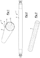
- propeller shaft assembly 2 having a propeller shaft member 10 and a viscoelastic, soy-based foam liner 12 according to some embodiments of the present teachings disposed therein.
- Propeller shaft 10 can be a tubular member having a generally cylindrical shape and a hollow interior volume 14. It should be appreciated that propeller shaft 10 can define any cross-sectional shape conducive to a particular application, such as square, rectangular, octagonal, or any other shape operable for rotation.
- propeller shaft 10 can be used for any rotational application, such as a driveshaft for an automotive vehicle, a propeller shaft for a marine application, a propeller shaft for an aeronautical application, a transmission shaft for an industrial application, or any other rotating shaft used to transmit a torque.
- a cylindrical automotive drive shaft which will be generally indicated as 10, having opposing ends operably coupled to adjacent drive members.
- the opposing ends of the drive shaft can be coupled using conventional universal joint members.
- description of this particular embodiment should not be regarded as limiting the present application, unless specifically stated or claimed.
- cylindrical propeller shaft 10 can comprise a generally uniform sidewall 16 extending the length thereof having a generally constant outer diameter, inner diameter, and corresponding wall thickness.
- propeller shafts having non-uniform or varying diameter and/or wall thicknesses are anticipated as being part of the present teachings (as illustrated in FIG. 2 ).
- Propeller shaft 10 can be made of a conventional material, such as steel, aluminum, and/or other metal, metal alloy, or suitable material. It should also be understood that in some embodiments, propeller shaft 10 can be made of a composite material or plastic material as may be necessary for a particular application.
- viscoelastic, soy-based foam liner 12 is disposed through at least a longitudinal portion of volume 14 of propeller shaft 10 to fill at least a cross-sectional portion of volume 14 of propeller shaft 10. In some embodiments, viscoelastic, soy-based foam liner 12 substantially fills volume 14 of propeller shaft 10 in both a longitudinal direction and a cross-sectional direction. In some embodiments, viscoelastic, soy-based foam liner 12 completely fills volume 14 of propeller shaft 10 in both the longitudinal and cross-sectional directions. In some embodiments, liner 12 can be inflexible.
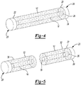
- viscoelastic, soy-based foam liner 12 can comprise a generally cylindrical cross-section having a longitudinally-extending bore or hollow volume 18. Hollow volume 18 can extend along the longitudinal axis of viscoelastic, soy-based foam liner 12. This configuration may provide the benefit of reduced weight without substantially sacrificing performance capabilities relating to noise, vibration, and harshness damping.
- optional end caps 20 can be formed on opposing ends 22 of viscoelastic, soy-based foam liner 12. End caps 20 can define a first portion 24 having an outer size and shape generally equal to an outer size and shape of viscoelastic, soy-based foam liner 12.
- End caps 20 can further define a second portion 26 extending from first portion 24 and integrally formed therewith having an outer size and shape generally equal to an inner size and shape of volume 18 of viscoelastic, soy-based foam liner 12 to permit second portion 26 to be received therein.
- liner 12 being formed with hollow volume 18 can be achieved using liners made of any one of a number of materials-that is, the principles of the liner having a longitudinally extending hollow volume should not be regarded as being limited to applications employing a viscoelastic, soy-based foam liner.
- viscoelastic, soy-based foam liner 12 can be formed in two or more separate, discrete sections 30, 32 ( FIG. 5 ).
- Discrete sections 30, 32 can be separated along a plane or other surface in a direction generally orthogonal to the longitudinal axis of viscoelastic, soy-based foam liner 12. In this way, discrete sections 30, 32 can be positioned within volume 14 of propeller shaft 10. It has been found that this configuration can provide the benefit of reduced weight without substantially sacrificing performance capabilities relating to noise, vibration, and harshness damping. It should be noted that the number of discrete sections shall not be construed as being limited.
- liner 12 being formed as discrete sections 30, 32 can be achieved using liners made of any one of a number of materials-that is, the principles of the discrete sections 30, 32 should not be regarded as being limited to applications employing a viscoelastic, soy-based foam liner.
- Viscoelastic, soy-based foam liner 12 can be constructed as a longitudinal member having a cross-sectional shape that is different than a final cross-sectional shape for use in propeller shaft 10.
- viscoelastic, soy-based foam liner 12 can be constructed from a foam material as an elongated member having a square or rectangular or arbitrary cross-section.
- the square or rectangular cross-section can be modified, such as on a lathe, a CNC machine, by hot wire, by skiving, or through the insertion of foam liner 12 into propeller shaft 10, into a final cross-section that closely conforms to the internal shape of propeller shaft 10.
- foam liner 12 is modified from a rectangular cross-section to a circular cross-section to define an outside diameter that is greater than the inner diameter of volume 14 of propeller shaft 10 to permit a press-fit to be achieved upon insertion of foam liner 12 into volume 14 of propeller shaft 10. This press-fit permits foam liner 12 to be retained within propeller shaft 10 for rotation therewith during operation and when exposed to application of torque, temperature, humidity, and the like.
- foam liner 12 can be created from its constituent chemicals in liquid form by inserting the constituent chemicals into propeller shaft 10.
- the liquid chemicals expand and solidify to define a solid (i.e. non-liquid) state foam.
- this liquid can be deposited within propeller shaft 10 without pre-treating the inside of propeller shaft 10 to prevent adhesion.
- propeller shaft 10 can be pre-treated with a release agent or other material to prevent or at least inhibit adhesion of foam liner 12 to the inner surface of propeller shaft 10.
- The, viscoelastic, soy-based foam liner 12 is made of a foam material that is derived from a blend of petroleum-based polyether polyol and a soy-based polyol prepared by the oxidation of RBD grade soybean oil with a peroxy carboxylic acid. It should be understood that RBD grade oil is not required in all embodiments and lesser grade oil can be used.
- viscoelastic, soy-based foam liner 12 can be described in relation to its physical and mechanical properties, and relative to those of liners made from other materials, as summarized in Table 1 below: Table 1: Physical and Mechanical Properties Foam Identification Description Density [kg/m 3 ] Air Flow [cfm] Resilience Ball Rebound [%] Young' s Modulus [kPa] Damp-ingRa-tio [%] Non-soy FFNV H Traditional driveshaft foam 25 2.10 38 60 5.6 FF501 Conventional, non-soy foam 23 5.00 36 50 4.0 Soy FF502 Conventional, soy-based foam 30 php Agrol 3.6 25 1.75 21 90 6.5 FF503 Conventional, soy-based foam 30 php Agrol 3.6 21 2.00 22 80 6.4 FF504 Conventional, soy-based foam 50 php Agrol 3.6 22 1.00 15 80 7.9 Viscoelastic Soy FF505 Viscoelastic, soy-based foam
- Table 1 illustrates measured physical characteristics of various types of foam.
- air flow provides a sense of the porosity of the foam. The greater the air flow, the greater the porosity.
- the viscoelastic foam liner 12 has much lower porosity than the other foams. It should be noted that the stated parts per hundred of polyol (php) is a percentage of soy in the polyol blend rather than in the foam.
- resilience is a measure of how readily the foam recovers its initial shape after deformation.
- resilience was measured using a ball rebound test which can be correlated to resilience.
- the viscoelastic foam liner 12 has very low resilience compared to the other foams meaning it recovers more slowly from deformation.
- Young's modulus is the elastic stiffness of the foams. It is a measure of how much the foams will structurally bend or elongate due to, respectively, a specific bending moment or a specific axial force.
- the viscoelastic foam liner 12 was found to have similar stiffness compared to the other, and this value is suitably low for the propeller shaft application. It is generally desirable to limit the amount of stiffness exerted by viscoelastic foam liner 12 to propeller shaft 10 in which it is contained.
- Damping ratio is the most important property for this application. It is a measure of how readily the material dissipates energy during vibration.
- the viscoelastic foam liner 12 of the present teachings has significantly higher damping than the others, so if the foams are subjected to the same vibration, the amplitude of the vibration will dissipate most rapidly in the viscoelastic foam liner 12. Also, this property is generally able to reduce vibration of other components which are in contact with, or connected to, viscoelastic foam liner 12. The ability of viscoelastic foam liner 12 to damp vibrations in connected components is also affected by the nature of the connection, friction, the other material, etc. But generally speaking, higher damping is desired.
- the viscoelastic foam liner readily reduces the vibration of other connected or in-contact components, it will also readily inhibit the emanation of sound energy from those components. Furthermore, the viscoelastic foam liner will be effective at dissipating sound energy passing into it from nearby components, or components to which it is indirectly connected though the propeller shaft in which it lies, such as a motor vehicle engine or transmission.
- viscoelastic foam liner 12 can comprise a formulation with TDI isocyanate and a blend comprising a 1,000 molecular weight, petroleum-based polyether polyol and a soy-based polyol prepared by the oxidation of RBD grade or lesser grade soybean oil with a peroxy carboxylic acid.
- TDI isocyanate a formulation with TDI isocyanate and a blend comprising a 1,000 molecular weight, petroleum-based polyether polyol and a soy-based polyol prepared by the oxidation of RBD grade or lesser grade soybean oil with a peroxy carboxylic acid.
- FIGS. 6A-6C frequency response functions of propeller shaft 10 having universal joints in a free-free support condition are presented, specifically FIG. 6A presents frequency response functions for a shaft having no damper, FIG. 6B presents frequency response functions for a shaft having a conventional cardboard liner damper, and FIG. 6C presents frequency response functions for a shaft having viscoelastic foam liner 12. It can be seen by the presence of frequency spikes that through the use of viscoelastic foam liner 12 ( FIG. 6C ), there is a reduction of the peak values of most of these spikes, indicating increased damping, relative to a dampener-less condition or a cardboard liner condition. For additional specifics, attention should be directed to FIGS. 8A-8D illustrating vibration and noise levels of a propeller shaft with viscoelastic, soy-based foam liner 12 ( FIGS. 8A & 8C ) versus conventional cardboard liners ( FIGS. 8B & 8D ).
Landscapes
- Engineering & Computer Science (AREA)
- Mechanical Engineering (AREA)
- General Engineering & Computer Science (AREA)
- Ocean & Marine Engineering (AREA)
- Chemical & Material Sciences (AREA)
- Combustion & Propulsion (AREA)
- Aviation & Aerospace Engineering (AREA)
- Physics & Mathematics (AREA)
- Acoustics & Sound (AREA)
- Shafts, Cranks, Connecting Bars, And Related Bearings (AREA)
Claims (12)
- Antriebswellenanordnung mit:einem Antriebswellenelement (10), das ein Innenvolumen (14) aufweist; undmit einem Schaumauskleidungselement (12), das in mindestens einem Bereich des Innenvolumens (14) des Antriebswellenelements (10) angeordnet ist, wobei das Schaumauskleidungselement (12) aus einem Schaum hergestellt ist, wobei das Schaumauskleidungselement (12) dazu ausgebildet ist, die innerhalb des Antriebswellenelementes (10) auftretenden Vibrationsamplituden im Vergleich zu einem ungedämpften Antriebswellenelement zu reduzieren, dadurch gekennzeichnet, dass das Schaumauskleidungselement (12) aus einem viskoelastischen Schaum auf Naturöl-Polyol-Basis ist, der aus einer Mischung aus einem Erdöl-basierten Polyether-Polyol und einem Polyol auf Sojabasis abgeleitet ist, das aus der Oxidation von Sojabohnenöl mit einer peroxiden Carbonsäure hergestellt ist, wobei das Sojabohnenöl einen RBD-Grad oder weniger hat.
- Antriebswellenanordnung nach Anspruch 1, bei der das Schaumauskleidungselement (12) aus einem viskoelastischen Schaum auf Sojabohnenbasis mit einem niedrigen Molekulargewicht hergestellt ist.
- Antriebswellenanordnung nach Anspruch 1, bei der das Schaumauskleidungselement (12) ein massives zylindrisches Element aufweist, das sich entlang eines wesentlichen Teils des Innenvolumens der Antriebswelle erstreckt.
- Antriebswellenanordnung nach Anspruch 1, bei der das Schaumauskleidungselement (12) eine Mehrzahl von diskreten Elementen (30, 32) aufweist, die sich entlang eines Teils des Innenvolumens (14) der Antriebswelle (10) erstrecken.
- Antriebswellenanordnung nach Anspruch 1, bei der das Schaumauskleidungselement (12) ein im Wesentlichen hohles Volumen (18) aufweist, das sich entlang von wenigstens einem Teil der Längsachse des Schaumauskleidungselements (12) erstreckt.
- Antriebswellenanordnung nach Anspruch 5, die ferner Folgendes aufweist:
eine Endkappe (20), die an ein Ende des Schaumauskleidungselements (12) angekoppelt ist, wobei die Endkappe (20) einen ersten Bereich (24) aufweist, der eine solche Größe und Form aufweist, dass er eng an einen Außendurchmesser des Schaumauskleidungselements (12) angepasst ist, und einen zweiten Bereich (26) aufweist, der eine solche Form und Größe aufweist, dass er eng an einen Innendurchmesser des allgemein hohlen Volumens (18) angepasst ist, wobei der erste Bereich (24) und der zweite Bereich (26) miteinander einstückig ausgebildet sind. - Antriebswellenanordnung nach Anspruch 5, die ferner Folgendes aufweist:
eine Endkappe (20), die an ein Ende (22) des Schaumauskleidungselements (12) angekoppelt ist, wobei die Endkappe (20) einen Bereich aufweist, der eine solche Größe und Form aufweist, dass er eng an einen Außendurchmesser des Schaumauskleidungselements (12) angepasst ist. - Antriebswellenanordnung nach Anspruch 1, bei der das Schaumauskleidungselement (12) eine solche Größe und Form aufweist, dass es eine Außenabmessung definiert, die größer als eine Innenabmessung des Innenvolumens (14) der Antriebswelle (10) aufweist.
- Antriebswellenanordnung nach Anspruch 1, bei der das Schaumauskleidungselement (12) eine solche Größe und Form aufweist, dass eine Außenabmessung definiert wird, die größer als eine Innenabmessung des Innenvolumens der Antriebswelle (10) ist, um eine Presspassungsverbindung zu definieren.
- Antriebswellenanordnung nach Anspruch 1, die ferner Folgendes aufweist:
ein Trennmittel, das entlang wenigstens einem Teil des Innenvolumens der Antriebswelle (10) angeordnet ist, um ein Anhaften des Schaumauskleidungselements (12) daran zu hemmen. - Antriebswellenanordnung nach Anspruch 1, bei der das Antriebswellenelement gegenüberliegende Längsenden (22) aufweist und das Schaumauskleidungselement (12) ein kontinuierliches Element ist, das das Innenvolumen (14) des Antriebswellenelements (10) im Wesentlichen ausfüllt und sich zwischen den sich gegenüberliegenden Längsenden (22) erstreckt.
- Antriebswellenanordnung nach Anspruch 1, bei der das Schaumauskleidungselement (12) anfangs in dem Innenvolumen (14) des Antriebswellenelements (10) in einer flüssigen Form angeordnet ist und dann in eine feste Form expandiert, während es sich in dem Innenvolumen (14) der Antriebswellenanordnung (10) befindet.
Applications Claiming Priority (3)
| Application Number | Priority Date | Filing Date | Title |
|---|---|---|---|
| US201361824000P | 2013-05-16 | 2013-05-16 | |
| US14/278,260 US9340269B2 (en) | 2013-05-16 | 2014-05-15 | Viscoelastic dampener |
| PCT/US2014/038332 WO2014186664A1 (en) | 2013-05-16 | 2014-05-16 | Viscoelastic dampener |
Publications (3)
| Publication Number | Publication Date |
|---|---|
| EP2997281A1 EP2997281A1 (de) | 2016-03-23 |
| EP2997281A4 EP2997281A4 (de) | 2017-01-04 |
| EP2997281B1 true EP2997281B1 (de) | 2018-09-26 |
Family
ID=51896205
Family Applications (1)
| Application Number | Title | Priority Date | Filing Date |
|---|---|---|---|
| EP14797985.0A Active EP2997281B1 (de) | 2013-05-16 | 2014-05-16 | Viskoelastischer dämpfer |
Country Status (5)
| Country | Link |
|---|---|
| US (1) | US9340269B2 (de) |
| EP (1) | EP2997281B1 (de) |
| CA (1) | CA2912686C (de) |
| MX (1) | MX378805B (de) |
| WO (1) | WO2014186664A1 (de) |
Families Citing this family (6)
| Publication number | Priority date | Publication date | Assignee | Title |
|---|---|---|---|---|
| CN107580661B (zh) | 2015-05-11 | 2019-09-06 | 洛德公司 | 用于具有弯曲模态的中空轴、支柱和梁的阻尼装置、系统及方法 |
| US9975376B2 (en) * | 2015-12-21 | 2018-05-22 | Goodrich Corporation | Axle damper insert |
| CN108087493A (zh) * | 2016-11-23 | 2018-05-29 | 通用汽车环球科技运作有限责任公司 | 复合材料交通工具轴组件 |
| JP2019143873A (ja) * | 2018-02-21 | 2019-08-29 | 株式会社ホクエイ | 液体燃料供給装置 |
| US20200318710A1 (en) * | 2019-04-03 | 2020-10-08 | Ufp Technologies, Inc. | Temporarily Condensed Shaft Damper |
| WO2024128331A1 (ko) * | 2022-12-12 | 2024-06-20 | 주식회사 동우정공 | 소음저감 목적의 추진축커버를 갖는 차량용 동력전달장치 |
Citations (1)
| Publication number | Priority date | Publication date | Assignee | Title |
|---|---|---|---|---|
| WO2008036173A1 (en) * | 2006-09-21 | 2008-03-27 | Dow Global Technologies Inc. | Viscoelastic foams having high air flow |
Family Cites Families (19)
| Publication number | Priority date | Publication date | Assignee | Title |
|---|---|---|---|---|
| US2001166A (en) * | 1933-11-27 | 1935-05-14 | Borg Warner | Propeller shaft |
| US3075406A (en) * | 1961-07-13 | 1963-01-29 | Gen Motors Corp | Propeller shaft damper |
| US3659434A (en) * | 1971-01-15 | 1972-05-02 | Pittsburgh Tubular Shafting In | Method for balancing tubular shafting |
| JPS6256612A (ja) | 1985-09-04 | 1987-03-12 | Kioritz Corp | 携帯作業機用動力伝動軸 |
| JPH01112046A (ja) | 1987-10-24 | 1989-04-28 | Toyota Motor Corp | 制振推進軸の製造方法 |
| EP0324894A3 (de) | 1988-01-21 | 1990-09-19 | Helmut Pelzer | Schwingungsgedämpfte Welle und Verfahren zu ihrer Herstellung |
| JP3064818B2 (ja) | 1994-08-29 | 2000-07-12 | 三菱自動車工業株式会社 | 繊維強化樹脂製プロペラシャフト |
| US6234911B1 (en) * | 1996-09-16 | 2001-05-22 | Spicer Driveshaft, Inc. | Driveshaft assembly having a noise reduction structure |
| US5976021A (en) * | 1997-07-14 | 1999-11-02 | Arrow Paper Products, Co. | Drive shaft damper |
| US6601659B2 (en) | 2001-05-17 | 2003-08-05 | Hilti Aktiengesellschaft | Twist drill |
| US6752722B2 (en) * | 2002-03-13 | 2004-06-22 | American Axle & Manufacturing, Inc. | Foam lined propshaft |
| US7208531B2 (en) * | 2003-06-26 | 2007-04-24 | Basf Corporation | Viscoelastic polyurethane foam |
| US7134964B2 (en) * | 2003-08-20 | 2006-11-14 | Gkn Driveline North America, Inc. | Propeller shaft assembly with stiffening feature |
| US7083523B2 (en) * | 2004-03-04 | 2006-08-01 | Automotive Components Holdings, Llc | Damper for a vehicle torque transferring assembly |
| US20060041155A1 (en) | 2004-08-23 | 2006-02-23 | Biobased Chemical | Method of preparing a hydroxy functional vegetable oil |
| US20070072688A1 (en) * | 2005-07-13 | 2007-03-29 | Dickson John A | Driveshaft system |
| WO2008063594A1 (en) | 2006-11-16 | 2008-05-29 | Cargill, Incorporated | Viscoelastic polyurethane foams comprising oligomeric natural oil polyols |
| US8426482B2 (en) | 2008-10-24 | 2013-04-23 | Basf Se | Method for producing viscoelastic polyurethane flexible foams |
| CN103906778B (zh) * | 2011-09-29 | 2015-11-25 | 陶氏环球技术有限责任公司 | 粘弹性泡沫体 |
-
2014
- 2014-05-15 US US14/278,260 patent/US9340269B2/en active Active
- 2014-05-16 CA CA2912686A patent/CA2912686C/en active Active
- 2014-05-16 EP EP14797985.0A patent/EP2997281B1/de active Active
- 2014-05-16 MX MX2015015856A patent/MX378805B/es unknown
- 2014-05-16 WO PCT/US2014/038332 patent/WO2014186664A1/en not_active Ceased
Patent Citations (1)
| Publication number | Priority date | Publication date | Assignee | Title |
|---|---|---|---|---|
| WO2008036173A1 (en) * | 2006-09-21 | 2008-03-27 | Dow Global Technologies Inc. | Viscoelastic foams having high air flow |
Also Published As
| Publication number | Publication date |
|---|---|
| US20140342841A1 (en) | 2014-11-20 |
| CA2912686C (en) | 2020-02-11 |
| US9340269B2 (en) | 2016-05-17 |
| WO2014186664A1 (en) | 2014-11-20 |
| MX2015015856A (es) | 2016-06-21 |
| CA2912686A1 (en) | 2014-11-20 |
| EP2997281A1 (de) | 2016-03-23 |
| MX378805B (es) | 2025-03-11 |
| EP2997281A4 (de) | 2017-01-04 |
Similar Documents
| Publication | Publication Date | Title |
|---|---|---|
| CA2912686C (en) | Viscoelastic dampener | |
| US9920813B2 (en) | Dynamic damper assembly | |
| KR102031167B1 (ko) | 댐퍼를 갖는 프로프샤프트 조립체를 조립하기 위한 방법 | |
| US6666771B2 (en) | Crash optimized plunging CV joint | |
| JPH05231455A (ja) | 内蔵ストッパにより制御される軸方向あそび及び高いろ過能をもつ弾性継手及びその利用方法 | |
| WO2007100593A3 (en) | Method for attenuating driveline vibrations | |
| CN100366455C (zh) | 传动轴 | |
| CN105008742A (zh) | 联结器 | |
| US7083523B2 (en) | Damper for a vehicle torque transferring assembly | |
| US20070105461A1 (en) | Propeller shaft assembly with energy absorbing material | |
| CN101285507B (zh) | 万向节 | |
| US6817771B2 (en) | Center bearing tuned absorber | |
| WO2009064284A1 (en) | Drive shaft with array tuned absorber | |
| JP2008082550A (ja) | トルク移送アセンブリ用の調整可能なダンパ | |
| EP3184337A1 (de) | Anordnung zur rotationsentkopplung von motor und getriebe | |
| CN107606053A (zh) | 扭转减震器、传动轴和车辆 | |
| JP2011064326A (ja) | シャフト組立体 | |
| US20170204936A1 (en) | Dual mode tuning type dynamic damper and drive shaft device and vehicle thereby | |
| US10690210B2 (en) | Mount assembly for a vehicle | |
| CN106870635B (zh) | 用于车辆传动轴的动态减震器 | |
| CN104204580A (zh) | 转向柱减震元件和转向柱装置 | |
| JPH01283427A (ja) | 振動が減衰される軸 | |
| KR100804583B1 (ko) | 유니버셜 조인트 | |
| KR101214269B1 (ko) | 자동차 조향장치의 슬립 조인트 | |
| JP4633751B2 (ja) | 防振装置 |
Legal Events
| Date | Code | Title | Description |
|---|---|---|---|
| PUAI | Public reference made under article 153(3) epc to a published international application that has entered the european phase |
Free format text: ORIGINAL CODE: 0009012 |
|
| 17P | Request for examination filed |
Effective date: 20151215 |
|
| AK | Designated contracting states |
Kind code of ref document: A1 Designated state(s): AL AT BE BG CH CY CZ DE DK EE ES FI FR GB GR HR HU IE IS IT LI LT LU LV MC MK MT NL NO PL PT RO RS SE SI SK SM TR |
|
| AX | Request for extension of the european patent |
Extension state: BA ME |
|
| DAX | Request for extension of the european patent (deleted) | ||
| A4 | Supplementary search report drawn up and despatched |
Effective date: 20161201 |
|
| RIC1 | Information provided on ipc code assigned before grant |
Ipc: F16F 7/104 20060101AFI20161125BHEP Ipc: F16F 15/12 20060101ALI20161125BHEP |
|
| STAA | Information on the status of an ep patent application or granted ep patent |
Free format text: STATUS: EXAMINATION IS IN PROGRESS |
|
| 17Q | First examination report despatched |
Effective date: 20170906 |
|
| GRAP | Despatch of communication of intention to grant a patent |
Free format text: ORIGINAL CODE: EPIDOSNIGR1 |
|
| STAA | Information on the status of an ep patent application or granted ep patent |
Free format text: STATUS: GRANT OF PATENT IS INTENDED |
|
| INTG | Intention to grant announced |
Effective date: 20180406 |
|
| GRAS | Grant fee paid |
Free format text: ORIGINAL CODE: EPIDOSNIGR3 |
|
| GRAA | (expected) grant |
Free format text: ORIGINAL CODE: 0009210 |
|
| STAA | Information on the status of an ep patent application or granted ep patent |
Free format text: STATUS: THE PATENT HAS BEEN GRANTED |
|
| AK | Designated contracting states |
Kind code of ref document: B1 Designated state(s): AL AT BE BG CH CY CZ DE DK EE ES FI FR GB GR HR HU IE IS IT LI LT LU LV MC MK MT NL NO PL PT RO RS SE SI SK SM TR |
|
| REG | Reference to a national code |
Ref country code: GB Ref legal event code: FG4D |
|
| REG | Reference to a national code |
Ref country code: CH Ref legal event code: EP |
|
| REG | Reference to a national code |
Ref country code: AT Ref legal event code: REF Ref document number: 1046389 Country of ref document: AT Kind code of ref document: T Effective date: 20181015 |
|
| REG | Reference to a national code |
Ref country code: IE Ref legal event code: FG4D |
|
| REG | Reference to a national code |
Ref country code: DE Ref legal event code: R096 Ref document number: 602014033085 Country of ref document: DE |
|
| REG | Reference to a national code |
Ref country code: NL Ref legal event code: MP Effective date: 20180926 |
|
| PG25 | Lapsed in a contracting state [announced via postgrant information from national office to epo] |
Ref country code: FI Free format text: LAPSE BECAUSE OF FAILURE TO SUBMIT A TRANSLATION OF THE DESCRIPTION OR TO PAY THE FEE WITHIN THE PRESCRIBED TIME-LIMIT Effective date: 20180926 Ref country code: LT Free format text: LAPSE BECAUSE OF FAILURE TO SUBMIT A TRANSLATION OF THE DESCRIPTION OR TO PAY THE FEE WITHIN THE PRESCRIBED TIME-LIMIT Effective date: 20180926 Ref country code: BG Free format text: LAPSE BECAUSE OF FAILURE TO SUBMIT A TRANSLATION OF THE DESCRIPTION OR TO PAY THE FEE WITHIN THE PRESCRIBED TIME-LIMIT Effective date: 20181226 Ref country code: NO Free format text: LAPSE BECAUSE OF FAILURE TO SUBMIT A TRANSLATION OF THE DESCRIPTION OR TO PAY THE FEE WITHIN THE PRESCRIBED TIME-LIMIT Effective date: 20181226 Ref country code: GR Free format text: LAPSE BECAUSE OF FAILURE TO SUBMIT A TRANSLATION OF THE DESCRIPTION OR TO PAY THE FEE WITHIN THE PRESCRIBED TIME-LIMIT Effective date: 20181227 Ref country code: RS Free format text: LAPSE BECAUSE OF FAILURE TO SUBMIT A TRANSLATION OF THE DESCRIPTION OR TO PAY THE FEE WITHIN THE PRESCRIBED TIME-LIMIT Effective date: 20180926 Ref country code: SE Free format text: LAPSE BECAUSE OF FAILURE TO SUBMIT A TRANSLATION OF THE DESCRIPTION OR TO PAY THE FEE WITHIN THE PRESCRIBED TIME-LIMIT Effective date: 20180926 |
|
| REG | Reference to a national code |
Ref country code: LT Ref legal event code: MG4D |
|
| PG25 | Lapsed in a contracting state [announced via postgrant information from national office to epo] |
Ref country code: AL Free format text: LAPSE BECAUSE OF FAILURE TO SUBMIT A TRANSLATION OF THE DESCRIPTION OR TO PAY THE FEE WITHIN THE PRESCRIBED TIME-LIMIT Effective date: 20180926 Ref country code: HR Free format text: LAPSE BECAUSE OF FAILURE TO SUBMIT A TRANSLATION OF THE DESCRIPTION OR TO PAY THE FEE WITHIN THE PRESCRIBED TIME-LIMIT Effective date: 20180926 Ref country code: LV Free format text: LAPSE BECAUSE OF FAILURE TO SUBMIT A TRANSLATION OF THE DESCRIPTION OR TO PAY THE FEE WITHIN THE PRESCRIBED TIME-LIMIT Effective date: 20180926 |
|
| REG | Reference to a national code |
Ref country code: AT Ref legal event code: MK05 Ref document number: 1046389 Country of ref document: AT Kind code of ref document: T Effective date: 20180926 |
|
| PG25 | Lapsed in a contracting state [announced via postgrant information from national office to epo] |
Ref country code: IT Free format text: LAPSE BECAUSE OF FAILURE TO SUBMIT A TRANSLATION OF THE DESCRIPTION OR TO PAY THE FEE WITHIN THE PRESCRIBED TIME-LIMIT Effective date: 20180926 Ref country code: AT Free format text: LAPSE BECAUSE OF FAILURE TO SUBMIT A TRANSLATION OF THE DESCRIPTION OR TO PAY THE FEE WITHIN THE PRESCRIBED TIME-LIMIT Effective date: 20180926 Ref country code: EE Free format text: LAPSE BECAUSE OF FAILURE TO SUBMIT A TRANSLATION OF THE DESCRIPTION OR TO PAY THE FEE WITHIN THE PRESCRIBED TIME-LIMIT Effective date: 20180926 Ref country code: PL Free format text: LAPSE BECAUSE OF FAILURE TO SUBMIT A TRANSLATION OF THE DESCRIPTION OR TO PAY THE FEE WITHIN THE PRESCRIBED TIME-LIMIT Effective date: 20180926 Ref country code: IS Free format text: LAPSE BECAUSE OF FAILURE TO SUBMIT A TRANSLATION OF THE DESCRIPTION OR TO PAY THE FEE WITHIN THE PRESCRIBED TIME-LIMIT Effective date: 20190126 Ref country code: NL Free format text: LAPSE BECAUSE OF FAILURE TO SUBMIT A TRANSLATION OF THE DESCRIPTION OR TO PAY THE FEE WITHIN THE PRESCRIBED TIME-LIMIT Effective date: 20180926 Ref country code: CZ Free format text: LAPSE BECAUSE OF FAILURE TO SUBMIT A TRANSLATION OF THE DESCRIPTION OR TO PAY THE FEE WITHIN THE PRESCRIBED TIME-LIMIT Effective date: 20180926 Ref country code: RO Free format text: LAPSE BECAUSE OF FAILURE TO SUBMIT A TRANSLATION OF THE DESCRIPTION OR TO PAY THE FEE WITHIN THE PRESCRIBED TIME-LIMIT Effective date: 20180926 Ref country code: ES Free format text: LAPSE BECAUSE OF FAILURE TO SUBMIT A TRANSLATION OF THE DESCRIPTION OR TO PAY THE FEE WITHIN THE PRESCRIBED TIME-LIMIT Effective date: 20180926 |
|
| PG25 | Lapsed in a contracting state [announced via postgrant information from national office to epo] |
Ref country code: PT Free format text: LAPSE BECAUSE OF FAILURE TO SUBMIT A TRANSLATION OF THE DESCRIPTION OR TO PAY THE FEE WITHIN THE PRESCRIBED TIME-LIMIT Effective date: 20190126 Ref country code: SK Free format text: LAPSE BECAUSE OF FAILURE TO SUBMIT A TRANSLATION OF THE DESCRIPTION OR TO PAY THE FEE WITHIN THE PRESCRIBED TIME-LIMIT Effective date: 20180926 Ref country code: SM Free format text: LAPSE BECAUSE OF FAILURE TO SUBMIT A TRANSLATION OF THE DESCRIPTION OR TO PAY THE FEE WITHIN THE PRESCRIBED TIME-LIMIT Effective date: 20180926 |
|
| REG | Reference to a national code |
Ref country code: DE Ref legal event code: R097 Ref document number: 602014033085 Country of ref document: DE |
|
| PG25 | Lapsed in a contracting state [announced via postgrant information from national office to epo] |
Ref country code: DK Free format text: LAPSE BECAUSE OF FAILURE TO SUBMIT A TRANSLATION OF THE DESCRIPTION OR TO PAY THE FEE WITHIN THE PRESCRIBED TIME-LIMIT Effective date: 20180926 |
|
| PLBE | No opposition filed within time limit |
Free format text: ORIGINAL CODE: 0009261 |
|
| STAA | Information on the status of an ep patent application or granted ep patent |
Free format text: STATUS: NO OPPOSITION FILED WITHIN TIME LIMIT |
|
| 26N | No opposition filed |
Effective date: 20190627 |
|
| PG25 | Lapsed in a contracting state [announced via postgrant information from national office to epo] |
Ref country code: SI Free format text: LAPSE BECAUSE OF FAILURE TO SUBMIT A TRANSLATION OF THE DESCRIPTION OR TO PAY THE FEE WITHIN THE PRESCRIBED TIME-LIMIT Effective date: 20180926 |
|
| REG | Reference to a national code |
Ref country code: CH Ref legal event code: PL |
|
| PG25 | Lapsed in a contracting state [announced via postgrant information from national office to epo] |
Ref country code: CH Free format text: LAPSE BECAUSE OF NON-PAYMENT OF DUE FEES Effective date: 20190531 Ref country code: LI Free format text: LAPSE BECAUSE OF NON-PAYMENT OF DUE FEES Effective date: 20190531 Ref country code: MC Free format text: LAPSE BECAUSE OF FAILURE TO SUBMIT A TRANSLATION OF THE DESCRIPTION OR TO PAY THE FEE WITHIN THE PRESCRIBED TIME-LIMIT Effective date: 20180926 |
|
| REG | Reference to a national code |
Ref country code: BE Ref legal event code: MM Effective date: 20190531 |
|
| PG25 | Lapsed in a contracting state [announced via postgrant information from national office to epo] |
Ref country code: LU Free format text: LAPSE BECAUSE OF NON-PAYMENT OF DUE FEES Effective date: 20190516 |
|
| PG25 | Lapsed in a contracting state [announced via postgrant information from national office to epo] |
Ref country code: TR Free format text: LAPSE BECAUSE OF FAILURE TO SUBMIT A TRANSLATION OF THE DESCRIPTION OR TO PAY THE FEE WITHIN THE PRESCRIBED TIME-LIMIT Effective date: 20180926 |
|
| PG25 | Lapsed in a contracting state [announced via postgrant information from national office to epo] |
Ref country code: IE Free format text: LAPSE BECAUSE OF NON-PAYMENT OF DUE FEES Effective date: 20190516 |
|
| PG25 | Lapsed in a contracting state [announced via postgrant information from national office to epo] |
Ref country code: BE Free format text: LAPSE BECAUSE OF NON-PAYMENT OF DUE FEES Effective date: 20190531 |
|
| PG25 | Lapsed in a contracting state [announced via postgrant information from national office to epo] |
Ref country code: FR Free format text: LAPSE BECAUSE OF NON-PAYMENT OF DUE FEES Effective date: 20190531 |
|
| PG25 | Lapsed in a contracting state [announced via postgrant information from national office to epo] |
Ref country code: CY Free format text: LAPSE BECAUSE OF FAILURE TO SUBMIT A TRANSLATION OF THE DESCRIPTION OR TO PAY THE FEE WITHIN THE PRESCRIBED TIME-LIMIT Effective date: 20180926 |
|
| PG25 | Lapsed in a contracting state [announced via postgrant information from national office to epo] |
Ref country code: MT Free format text: LAPSE BECAUSE OF FAILURE TO SUBMIT A TRANSLATION OF THE DESCRIPTION OR TO PAY THE FEE WITHIN THE PRESCRIBED TIME-LIMIT Effective date: 20180926 Ref country code: HU Free format text: LAPSE BECAUSE OF FAILURE TO SUBMIT A TRANSLATION OF THE DESCRIPTION OR TO PAY THE FEE WITHIN THE PRESCRIBED TIME-LIMIT; INVALID AB INITIO Effective date: 20140516 |
|
| PG25 | Lapsed in a contracting state [announced via postgrant information from national office to epo] |
Ref country code: MK Free format text: LAPSE BECAUSE OF FAILURE TO SUBMIT A TRANSLATION OF THE DESCRIPTION OR TO PAY THE FEE WITHIN THE PRESCRIBED TIME-LIMIT Effective date: 20180926 |
|
| P01 | Opt-out of the competence of the unified patent court (upc) registered |
Effective date: 20230511 |
|
| PGFP | Annual fee paid to national office [announced via postgrant information from national office to epo] |
Ref country code: DE Payment date: 20250519 Year of fee payment: 12 |
|
| PGFP | Annual fee paid to national office [announced via postgrant information from national office to epo] |
Ref country code: GB Payment date: 20260326 Year of fee payment: 13 |