EP2997260B1 - Begrenzungsindikator zur rekonditionierung eines verdichterventilsitzes - Google Patents
Begrenzungsindikator zur rekonditionierung eines verdichterventilsitzes Download PDFInfo
- Publication number
- EP2997260B1 EP2997260B1 EP14798176.5A EP14798176A EP2997260B1 EP 2997260 B1 EP2997260 B1 EP 2997260B1 EP 14798176 A EP14798176 A EP 14798176A EP 2997260 B1 EP2997260 B1 EP 2997260B1
- Authority
- EP
- European Patent Office
- Prior art keywords
- seat
- reconditioning
- outlet surface
- limit indicator
- compressor valve
- Prior art date
- Legal status (The legal status is an assumption and is not a legal conclusion. Google has not performed a legal analysis and makes no representation as to the accuracy of the status listed.)
- Active
Links
Images


Classifications
-
- F—MECHANICAL ENGINEERING; LIGHTING; HEATING; WEAPONS; BLASTING
- F04—POSITIVE - DISPLACEMENT MACHINES FOR LIQUIDS; PUMPS FOR LIQUIDS OR ELASTIC FLUIDS
- F04B—POSITIVE-DISPLACEMENT MACHINES FOR LIQUIDS; PUMPS
- F04B39/00—Component parts, details, or accessories, of pumps or pumping systems specially adapted for elastic fluids, not otherwise provided for in, or of interest apart from, groups F04B25/00 - F04B37/00
- F04B39/10—Adaptations or arrangements of distribution members
- F04B39/1053—Adaptations or arrangements of distribution members the members being Hoerbigen valves
-
- F—MECHANICAL ENGINEERING; LIGHTING; HEATING; WEAPONS; BLASTING
- F04—POSITIVE - DISPLACEMENT MACHINES FOR LIQUIDS; PUMPS FOR LIQUIDS OR ELASTIC FLUIDS
- F04B—POSITIVE-DISPLACEMENT MACHINES FOR LIQUIDS; PUMPS
- F04B39/00—Component parts, details, or accessories, of pumps or pumping systems specially adapted for elastic fluids, not otherwise provided for in, or of interest apart from, groups F04B25/00 - F04B37/00
- F04B39/10—Adaptations or arrangements of distribution members
- F04B39/1013—Adaptations or arrangements of distribution members the members being of the poppet valve type
-
- F—MECHANICAL ENGINEERING; LIGHTING; HEATING; WEAPONS; BLASTING
- F16—ENGINEERING ELEMENTS AND UNITS; GENERAL MEASURES FOR PRODUCING AND MAINTAINING EFFECTIVE FUNCTIONING OF MACHINES OR INSTALLATIONS; THERMAL INSULATION IN GENERAL
- F16K—VALVES; TAPS; COCKS; ACTUATING-FLOATS; DEVICES FOR VENTING OR AERATING
- F16K1/00—Lift valves or globe valves, i.e. cut-off apparatus with closure members having at least a component of their opening and closing motion perpendicular to the closing faces
- F16K1/32—Details
- F16K1/34—Cutting-off parts, e.g. valve members, seats
- F16K1/42—Valve seats
-
- F—MECHANICAL ENGINEERING; LIGHTING; HEATING; WEAPONS; BLASTING
- F16—ENGINEERING ELEMENTS AND UNITS; GENERAL MEASURES FOR PRODUCING AND MAINTAINING EFFECTIVE FUNCTIONING OF MACHINES OR INSTALLATIONS; THERMAL INSULATION IN GENERAL
- F16K—VALVES; TAPS; COCKS; ACTUATING-FLOATS; DEVICES FOR VENTING OR AERATING
- F16K15/00—Check valves
- F16K15/02—Check valves with guided rigid valve members
- F16K15/025—Check valves with guided rigid valve members the valve being loaded by a spring
- F16K15/026—Check valves with guided rigid valve members the valve being loaded by a spring the valve member being a movable body around which the medium flows when the valve is open
-
- F—MECHANICAL ENGINEERING; LIGHTING; HEATING; WEAPONS; BLASTING
- F16—ENGINEERING ELEMENTS AND UNITS; GENERAL MEASURES FOR PRODUCING AND MAINTAINING EFFECTIVE FUNCTIONING OF MACHINES OR INSTALLATIONS; THERMAL INSULATION IN GENERAL
- F16K—VALVES; TAPS; COCKS; ACTUATING-FLOATS; DEVICES FOR VENTING OR AERATING
- F16K37/00—Special means in or on valves or other cut-off apparatus for indicating or recording operation thereof, or for enabling an alarm to be given
- F16K37/0008—Mechanical means
-
- Y—GENERAL TAGGING OF NEW TECHNOLOGICAL DEVELOPMENTS; GENERAL TAGGING OF CROSS-SECTIONAL TECHNOLOGIES SPANNING OVER SEVERAL SECTIONS OF THE IPC; TECHNICAL SUBJECTS COVERED BY FORMER USPC CROSS-REFERENCE ART COLLECTIONS [XRACs] AND DIGESTS
- Y10—TECHNICAL SUBJECTS COVERED BY FORMER USPC
- Y10T—TECHNICAL SUBJECTS COVERED BY FORMER US CLASSIFICATION
- Y10T137/00—Fluid handling
- Y10T137/0318—Processes
- Y10T137/0402—Cleaning, repairing, or assembling
- Y10T137/0441—Repairing, securing, replacing, or servicing pipe joint, valve, or tank
- Y10T137/0486—Specific valve or valve element mounting or repairing
Definitions
- the present disclosure relates to a compressor valve comprising a seat having a reconditioning limit indicator.
- a compressor valve may include a guard (also referred to as a stopplate) retaining a plurality of valve elements, and a seat disposed on the guard.
- the seat may define an array of inlet holes for working fluid to enter the compressor valve via the inlet holes and the guard may define an array of outlet holes disposed between the plurality of valve elements for the working fluid to exit the compressor valve.
- the plurality of valve elements may control the flow of working fluid into the compressor valve. Generally, when the valve elements seal the inlet holes, the working fluid is prevented from exiting the inlet holes (thereby from entering the valve) and when the valve elements unseal inlet holes, the working fluid enters the compressor valve and exits via the outlet holes on the guard.
- the edges of the inlet holes may deform in shape (e.g., develop crack, dents, or the like) and working fluid may enter the compressor valve when the valve element is in contact with the edge of the inlet hole.
- the seat is reconditioned by removing material from the surface of the seat facing the guard.
- a minimum seat thickness has to be maintained after reconditioning the seat. Failing to maintain a minimum seat thickness may result in improper operation and/or failure of the compressor valve. Accordingly, a known industry practice is for manufacturers of such compressor valves to provide the minimum seat thickness to the end-user via the compressor valve operation manual or as a separate sheet of paper detailing the reconditioning procedure.
- the end-user refers to the provided documentation to ensure that the seat is not reconditioned to a thickness less than the minimum allowable.
- the documentation cannot be kept with the compressor valve itself, it may often get lost or may be difficult to locate. This may lead to time wasted in locating the document, or the end-user may recondition the seat without knowledge of the minimum allowable thickness.
- US 4872481 discloses a poppet valve seat member with port exits having edges provided with a 30 degree chamfer and a counter-bore immediately upstream of the chamfer.
- Example embodiments of the disclosure may provide a compressor valve.
- the compressor valve may include a seat having an inlet surface and an outlet surface opposite the inlet surface.
- the seat may have a reconditioning limit indicator defined by or adjacent the outlet surface.
- the reconditioning limit indicator may be indicative of a maximum amount of material of the seat that may be removed from the outlet surface during reconditioning of the seat.
- Example embodiments of the disclosure may provide a method of reconditioning a seat of a compressor valve.
- the method may include separating the seat from a guard of the compressor valve, removing material of the seat from an outlet surface of the seat, and referencing a reconditioning limit indicator defined by or adjacent the outlet surface.
- the removal of the material from the seat may be based at least in part on the reconditioning limit indicator.
- the reconditioning limit indicator may indicate a maximum amount of the material of the seat that may be removed from the outlet surface during reconditioning of the seat.
- Example embodiments of the disclosure may provide another compressor valve.
- the compressor valve may include a cylindrical seat having an inlet surface and an outlet surface axially separated from the inlet surface.
- the cylindrical seat may define a plurality of inlet holes extending between the inlet surface and the outlet surface.
- the plurality of inlet holes may be coupled to respective openings defined by the outlet surface.
- the outlet surface may be beveled about each opening and may define a predetermined outer diameter for each opening.
- the cylindrical seat may have a reconditioning limit indicator defined by or adjacent the outlet surface.
- the reconditioning limit indicator may indicate a maximum amount of material of the seat that may be removed from the outlet surface such that the outlet surface about each opening may be re-beveled to have the predetermined outer diameter.
- first and second features are formed in direct contact
- additional features may be formed interposing the first and second features, such that the first and second features may not be in direct contact.
- Figure 1A illustrates a perspective view of an inlet surface 104 of a seat 101 of a conventional compressor valve 100.
- the seat 101 and a guard 102 are affixed to each other by any suitable means.
- Working fluid enters the compressor valve 100 via an array of inlet holes 103 defined by the seat 101.
- the inlet holes 103 extend between an inlet surface 104 and an outlet surface 105 ( Figure 1 B) of the seat 101.
- the guard 102 may be attached to the outlet surface 105 of the seat 101 and a plurality of valve elements (not shown) retained by the guard 102 may contact against the edges 108 of the inlet holes 103 on the outlet surface 105.
- the inlet holes 103 When the valve elements contact against the edges 108 of the inlet holes 103, the inlet holes 103 may be sealed and working fluid may be prevented from exiting the inlet holes 103.
- the seat and guard in the present disclosure have been illustrated as generally cylindrical structures with the seat, for example, having different outer diameters, this is a mere design choice and that the structure of the seat and guard may be varied to fit any number of applications without departing from the scope of the disclosure.
- Figure 1B illustrates the outlet surface 105 of the seat 101 of the conventional compressor valve 100 of Figure 1A in greater detail.
- the edges 108 of the openings of the inlet holes 103 on the outlet surface 105 are beveled.
- an outer diameter (O.D.) of the respective beveled openings of the inlet holes 103 on the outlet surface 105 may be between 1.765 and 1.791 centimeters (0.695 and 0.705 inches).
- O.D. outer diameter
- the surfaces of the valve elements that contact the edges 108 of the inlet holes 103 may be correspondingly beveled so as to create the seal between the valve elements and the inlet holes 103 to prevent the working fluid from exiting the inlet holes 103.
- the edges 108 of the inlet holes 103 may deform (e.g., the bevels at the edges of the inlet holes 103 may lose shape) and the seal between the valve elements and the inlet holes 103 may deteriorate.
- working fluid may exit the inlet hole 103 when the valve element is in contact with the edge 108 of the inlet hole 103.
- the seat 101 may be reconditioned by removing material from the outlet surface 105.
- the inlet holes 103 may be re-beveled such that the outer diameter (O.D.) of the bevels may be restored to between, for example, 1 .765 and 1 .791 centimeters (0.695 and 0.705 inches).
- O.D. outer diameter
- the inlet holes 103 may be re-beveled to other dimensions based on the corresponding compressor valve specifications.
- the aforementioned O.D. of the bevels may be desired for a normal operation of the compressor valve 100 including the seat 101. It should be noted that only material from the outlet surface 105 may be removed when reconditioning the seat 101.
- reconditioning the seat may reduce an axial extent of the seat 101 measured from the inlet surface 104 to the outlet surface 105 (referred to as the thickness of the seat).
- a reconditioning limit indicator (described below) may be provided on or adjacent the outlet surface 105.
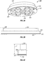
- Figure 2A illustrates a perspective view of a seat 201 having a reconditioning limit indicator 207, according to an example embodiment of the disclosure.
- Figure 2B illustrates a side view of the seat 201 in Figure 2A.
- Figure 2C illustrates an enlarged view of a portion of the seat 201 in Figure 2B enclosed by the dashed lines.
- the reconditioning limit indicator 207 may be a groove defined by the outer cylindrical surface 206 of the seat 201.
- the groove (e.g., a V-shaped groove) may be circumferentially disposed about the outer cylindrical surface 206 and may be further disposed proximal the outlet surface 205 of the seat 201 such that a distance between the inlet surface 204 and an edge of the groove distal (e.g., farthest) from the outlet surface 205 may indicate the minimum required thickness T of the seat 201 that may be desired for normal operation of the compressor valve including such a seat 201.
- the minimum required thickness T may also be the seat thickness desired so that the edges 208 of the inlet holes 203 may be re-beveled to a predetermined outer diameter between, for example, 1.765 and 1.791 centimeters (0.695 and 0.705 inches) after reconditioning the seat 201.
- the seat 201 may be reconditioned (material from the outlet surface 205 removed) only up to the groove edge farthest from the outlet surface 205. Any additional reconditioning of the seat 201 may reduce the minimum thickness T of the seat 201 and may cause improper operation and/or failure of the compressor valve. It should also be appreciated that the inlet holes 203 may be re-beveled to other dimensions based on the corresponding compressor valve specifications.
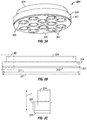
- Figure 3A illustrates a perspective view of a seat 301 having a reconditioning limit indicator 307, according to another example embodiment of the disclosure.
- Figure 3B illustrates a side view of the seat 301 of Figure 3A.
- Figure 3C illustrates an enlarged view of a portion of the seat 301 in Figure 3B enclosed by the dashed lines.
- material on the outer cylindrical surface 306 of the seat 301 adjacent (e.g., proximal) the outlet surface 305 may be removed to define the reconditioning limit indicator 307 having an outer diameter D1 smaller than the outer diameter D2 of the seat 301.
- An axial extent of the reconditioning limit indicator 307 between the outlet surface 305 and the inlet surface 304 may indicate the maximum amount of material that may be removed from the outlet surface 305 when reconditioning the seat 301. Stated otherwise, an axial extent from the inlet surface 304 of the seat 301 to the edge of the reconditioning limit indicator 307 farthest from the outlet surface 305 may indicate the minimum seat thickness T that may be desired for normal operation of the compressor valve including such a seat 301. Accordingly, reconditioning of the seat beyond the reconditioning limit indicator 307 may result in a decrease in the minimum required thickness T and may result in improper operation and/or failure of the compressor valve including the seat.
- the minimum required thickness T may also be the seat thickness desired so that the edges 308 of the inlet holes 303 may be re-beveled to a predetermined outer diameter between, for example, 1.765 and 1.791 centimeters (0.695 and 0.705 inches) after reconditioning the seat 301.
- the inlet holes 303 may be re-beveled to other dimensions based on the corresponding compressor valve specifications.
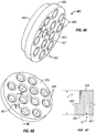
- Figure 4A illustrates a perspective view of a seat 401 having a reconditioning limit indicator 407, according to yet another example embodiment of the disclosure.
- Figure 4B illustrates another perspective view of the seat 401 of Figure 4A illustrating an exemplary location of the reconditioning limit indicator 407 on the outlet surface 405 of the seat 401.
- Figure 4C illustrates a cross-sectional view of the seat 401 in Figure 4B taken along the line 4C-4C in Figure 4B .
- the reconditioning limit indicator 407 may have a predetermined shape (illustrated as the letter 'M' in Figures 4A and 4B ) and a predetermined depth D ( Figure 4C ), and may be machined on the outlet surface 405.
- the depth D of the reconditioning limit indicator 407 may be such that an axial extent of the seat 401 between the inlet surface 404 and the bottom of the reconditioning limit indicator 407 may indicate the minimum required thickness T of the seat 401 that may be desired for normal operation of the compressor valve including such a seat 401. Accordingly, the seat 401 may be reconditioned (material from the outlet surface 405 removed) only to the depth D of the reconditioning limit indicator 407. Removing any material beyond the depth D may decrease the minimum seat thickness T and may cause improper operation and/or failure of the compressor valve including the seat 401.
- the minimum required thickness T may also be the seat thickness desired so that the edges 408 of the inlet holes 403 may be re-beveled to a predetermined outer diameter between, for example, 1.765 and 1.791 centimeters (0.695 and 0.705 inches) after reconditioning the seat 401.
- the inlet holes 403 may be re-beveled to other dimensions based on the corresponding compressor valve specifications.
- FIG. 5 is flowchart of a method 500 of reconditioning a seat of a compressor valve, according to an example embodiment of the disclosure.
- the method 500 may include separating the seat from a guard of the compressor valve, as shown at 502, removing material of the seat from an outlet surface of the seat, as shown at 504, and referencing a reconditioning limit indicator defined by or adjacent the outlet surface, whereby removal of the material from the seat is based at least in part on the reconditioning limit indicator, as shown at 506.
- the reconditioning limit indicator may indicate a maximum amount of the material of the seat that may be removed from the outlet surface during reconditioning of the seat.
- Seats including the reconditioning limit indicator according to example embodiments disclosed above may allow for individuals to recondition the seat without reference to an external document or device. As a result, time spent in locating and referring to the documentation to determine the minimum seat thickness prior to reconditioning the seat may be minimized.
- the seat may be reconditioned by individuals without access to the documentation or device. Since the reconditioning limit indicator may be provided on the seat itself, individual without access to the documentation or device or without knowledge of the minimum seat thickness may be able to recondition the seat. This may result in cost and time savings since the reconditioning job may be outsourced to third-party machining shops.
Landscapes
- Engineering & Computer Science (AREA)
- General Engineering & Computer Science (AREA)
- Mechanical Engineering (AREA)
- Compressor (AREA)
- Structures Of Non-Positive Displacement Pumps (AREA)
Claims (14)
- Verdichterventil, umfassend:einen Sitz (201, 301, 401) mit einer Einlassfläche (204, 304, 404) und einer der Einlassfläche gegenüberliegenden Auslassfläche (205, 305, 405), dadurch gekennzeichnet, dass der Sitz eine Begrenzungsanzeige (207, 307, 407) für die Instandsetzung aufweist, die durch die Auslassfläche definiert ist oder an diese angrenzt, wobei die Begrenzungsanzeige für die Instandsetzung eine Höchstmenge an Material des Sitzes anzeigt, die während der Instandsetzung des Sitzes von der Auslassfläche abgetragen werden kann.
- Verdichterventil nach Anspruch 1, wobei es sich bei der Begrenzungsanzeige (207, 307, 407) für die Instandsetzung um eine durch eine zylindrische Außenfläche (206, 306, 406) des Sitzes definierte Nut handelt, wobei sich die Nut in Nähe zur Auslassfläche (205, 305, 405) befindet.
- Verdichterventil nach Anspruch 2, wobei ein Abstand zwischen der Auslassfläche (205, 305, 405) und einem von der Auslassfläche entfernten Rand der Nut die Höchstmenge des Materials des Sitzes (201, 301, 401) anzeigt, die während der Instandsetzung des Sitzes von der Auslassfläche abgetragen werden kann.
- Verdichterventil nach Anspruch 3, wobei eine axiale Erstreckung des Sitzes zwischen der Einlassfläche (204, 304, 404) und dem von der Auslassfläche (205, 305, 405) entfernten Rand der Nut eine erforderliche Mindestdicke des Sitzes definiert.
- Verdichterventil nach Anspruch 1, wobei die Begrenzungsanzeige (207, 307, 407) für die Instandsetzung durch eine an die Auslassfläche (205, 305, 405) angrenzende zylindrische Außenfläche (206, 306, 406) des Sitzes definiert ist, wobei sich die Begrenzungsanzeige für die Instandsetzung axial zwischen der Einlassfläche (204, 304, 404) und der Auslassfläche erstreckt und die Begrenzungsanzeige zur Instandsetzung einen Außendurchmesser aufweist, der kleiner ist als ein Außendurchmesser des Sitzes.
- Verdichterventil nach Anspruch 5, wobei die axiale Erstreckung der Begrenzungsanzeige (207, 307, 407) für die Instandsetzung die Höchstmenge des Materials des Sitzes anzeigt, die während der Instandsetzung des Sitzes von der Auslassfläche (205, 305, 405) abgetragen werden kann.
- Verdichterventil nach Anspruch 6, wobei eine axiale Erstreckung des Sitzes von der Einlassfläche (204, 304, 404) zu einem von der Auslassfläche entfernten Rand der Begrenzungsanzeige (207, 307, 407) für die Instandsetzung eine erforderliche Mindestdicke des Sitzes definiert.
- Verdichterventil nach Anspruch 1, wobei die Begrenzungsanzeige (207, 307, 407) für die Instandsetzung durch die Auslassfläche (205, 305, 405) des Sitzes definiert ist, wobei die Begrenzungsanzeige für die Instandsetzung eine vorab bestimmte Form und eine vorab bestimmte Tiefe aufweist, wobei die vorab bestimmte Tiefe die Höchstmenge des Materials des Sitzes anzeigt, das während der Instandsetzung des Sitzes von der Auslassfläche abgetragen werden kann.
- Verdichterventil nach Anspruch 8, wobei der Sitz eine Vielzahl sich zwischen der Einlassfläche (204, 304, 404) und der Auslassfläche (205, 305, 405) erstreckender Einlassöffnungen (203, 303, 403) definiert und die Begrenzungsanzeige (207, 307, 407) für die Instandsetzung durch die Auslassfläche zwischen der Vielzahl von Einlassöffnungen definiert ist.
- Verfahren (500) zum Instandsetzen eines Sitzes (201, 301, 401) eines Verdichterventils, wobei das Verfahren umfasst:Trennen des Sitzes von einem Hubfänger (102) des Verdichterventils,Abtragen von Material des Sitzes von einer Auslassfläche (205, 305, 405) des Sitzes undReferenzieren einer durch die Auslassfläche definierten oder an diese angrenzenden Begrenzungsanzeige (207, 307, 407) für die Instandsetzung, wodurch Abtragen des Materials vom Sitz zumindest teilweise auf der Grundlage der Begrenzungsanzeige für die Instandsetzung erfolgt, wobei die Begrenzungsanzeige für die Instandsetzung eine Höchstmenge des Materials des Sitzes anzeigt, die während der Instandsetzung des Sitzes von der Auslassfläche abgetragen werden kann.
- Verfahren nach Anspruch 10, wobei der Sitz (201, 301, 401) eine Vielzahl von Einlassöffnungen (203, 303, 403) definiert, die mit durch die Auslassfläche (205, 305, 405) definierten jeweiligen Öffnungen in Fluidverbindung stehen, wobei die Auslassfläche um jede Öffnung herum abgeschrägt ist, und das Verfahren ferner umfasst:Nachschrägen der jeweiligen Öffnungen, so dass ein Außendurchmesser einer oder mehrerer der jeweiligen Öffnungen zwischen 1,765 und 1,791 Zentimetern beträgt.
- Verfahren nach Anspruch 10, wobei es sich bei der Begrenzungsanzeige (207, 307, 407) für die Instandsetzung um eine durch eine zylindrische Außenfläche (206, 306, 406) des Sitzes (201, 301, 401) definierte und in Nähe zur Auslassfläche (205, 305, 405) liegende Nut handelt und das Verfahren ferner umfasst:Instandsetzen des Sitzes (201, 301, 401), so dass zumindest ein Abschnitt der Nut sichtbar ist.
- Verfahren nach Anspruch 10, wobei die Begrenzungsanzeige (207, 307, 407) für die Instandsetzung durch eine zylindrische Außenfläche (206, 306, 406) des Sitzes (201, 301, 401) als ein Abschnitt des Sitzes mit einem Außendurchmesser definiert ist, der kleiner ist als ein Außendurchmesser des Sitzes, und das Verfahren ferner umfasst:Instandsetzen des Sitzes (201, 301, 401), so dass zumindest ein Abschnitt der Begrenzungsanzeige (207, 307, 407) für die Instandsetzung sichtbar ist.
- Verfahren nach Anspruch 10, wobei es sich bei der Begrenzungsanzeige (207, 307, 407) für die Instandsetzung um eine vorab bestimmte, durch die Auslassfläche (205, 305, 405) definierte Form handelt, wobei die vorab bestimmte Form eine vorab bestimmte Tiefe aufweist, und das Verfahren ferner umfasst:Instandsetzen des Sitzes (201, 301, 401), so dass zumindest ein Teil der vorab bestimmten Form sichtbar ist.
Applications Claiming Priority (3)
| Application Number | Priority Date | Filing Date | Title |
|---|---|---|---|
| US201361823008P | 2013-05-14 | 2013-05-14 | |
| US14/272,650 US10781806B2 (en) | 2013-05-14 | 2014-05-08 | Compressor valve seat reconditioning limit indicator |
| PCT/US2014/037629 WO2014186249A2 (en) | 2013-05-14 | 2014-05-12 | Compressor valve seat reconditioning limit indicator |
Publications (3)
| Publication Number | Publication Date |
|---|---|
| EP2997260A2 EP2997260A2 (de) | 2016-03-23 |
| EP2997260A4 EP2997260A4 (de) | 2017-01-11 |
| EP2997260B1 true EP2997260B1 (de) | 2017-08-23 |
Family
ID=51895051
Family Applications (1)
| Application Number | Title | Priority Date | Filing Date |
|---|---|---|---|
| EP14798176.5A Active EP2997260B1 (de) | 2013-05-14 | 2014-05-12 | Begrenzungsindikator zur rekonditionierung eines verdichterventilsitzes |
Country Status (3)
| Country | Link |
|---|---|
| US (1) | US10781806B2 (de) |
| EP (1) | EP2997260B1 (de) |
| WO (1) | WO2014186249A2 (de) |
Families Citing this family (1)
| Publication number | Priority date | Publication date | Assignee | Title |
|---|---|---|---|---|
| US11384753B1 (en) | 2021-05-07 | 2022-07-12 | Dresser-Rand Company | Gas operated unloader valve |
Family Cites Families (16)
| Publication number | Priority date | Publication date | Assignee | Title |
|---|---|---|---|---|
| US2624587A (en) * | 1949-08-30 | 1953-01-06 | Thompson Prod Inc | Valve assembly |
| US3148697A (en) * | 1960-10-17 | 1964-09-15 | Clifford H Carr | Compressor valve |
| US3536094A (en) * | 1968-03-12 | 1970-10-27 | Flavious E Manley Jr | Compressor valve |
| US4018247A (en) * | 1975-02-28 | 1977-04-19 | Carr Clifford H | Springless ball valve for high speed compressors |
| US4402342A (en) * | 1981-10-16 | 1983-09-06 | Paget Win W | Compressor valve |
| US4489752A (en) * | 1982-09-28 | 1984-12-25 | Compressor Valve Services, Inc. | Guard guided multiple element flow configured poppet valve |
| US4483363A (en) * | 1983-09-21 | 1984-11-20 | Madoche Robert D | Compressor valve |
| US4872481A (en) * | 1985-03-12 | 1989-10-10 | Cooper Industries, Inc. | Poppet valve flow seat |
| AT391928B (de) * | 1989-09-27 | 1990-12-27 | Hoerbiger Ventilwerke Ag | Ventil, insbesondere fuer verdichter |
| US5139114A (en) * | 1991-03-18 | 1992-08-18 | Abex Corporation | Visible brake block wear indicator |
| US5511583A (en) * | 1995-01-24 | 1996-04-30 | Dover Resources, Inc. | Compressor valve |
| US5669411A (en) | 1995-12-14 | 1997-09-23 | Legros; Brian J. | Compressor valve |
| EP0985845A1 (de) * | 1998-09-11 | 2000-03-15 | Brembo S.p.A. | Bremsscheibe mit Mittel zur visuellen Verschleisskontrolle |
| AT412302B (de) * | 2000-03-28 | 2004-12-27 | Hoerbiger Ventilwerke Gmbh | Selbsttätiges ventil |
| AT504694B1 (de) * | 2006-12-22 | 2009-04-15 | Hoerbiger Kompressortech Hold | Selbsttatiges ringventil |
| CN202833042U (zh) | 2012-08-18 | 2013-03-27 | 随州亿丰泵业有限公司 | 一种空气压缩机吸气阀座 |
-
2014
- 2014-05-08 US US14/272,650 patent/US10781806B2/en active Active
- 2014-05-12 EP EP14798176.5A patent/EP2997260B1/de active Active
- 2014-05-12 WO PCT/US2014/037629 patent/WO2014186249A2/en not_active Ceased
Non-Patent Citations (1)
| Title |
|---|
| None * |
Also Published As
| Publication number | Publication date |
|---|---|
| US20140339453A1 (en) | 2014-11-20 |
| EP2997260A2 (de) | 2016-03-23 |
| WO2014186249A3 (en) | 2015-04-09 |
| WO2014186249A2 (en) | 2014-11-20 |
| US10781806B2 (en) | 2020-09-22 |
| EP2997260A4 (de) | 2017-01-11 |
Similar Documents
| Publication | Publication Date | Title |
|---|---|---|
| EP3073276B1 (de) | Luftdatensonde mit verbesserter leistung beim betrieb unter einem hohen anstellwinkel | |
| JP6576332B2 (ja) | 内視鏡検査用開口部を含むターボ機械のケース | |
| EP2955423B1 (de) | Flussregelungsvorrichtung | |
| EP2997260B1 (de) | Begrenzungsindikator zur rekonditionierung eines verdichterventilsitzes | |
| EP2383062A1 (de) | Fräswerkzeug mit einer an ihrem Ende einen Aussengriff aufweisende Spannschraube | |
| BR112014005384B1 (pt) | recipiente de filtração | |
| EP2753854B1 (de) | Sicherheitskopf | |
| US9140586B2 (en) | Removable sensor port insert apparatus | |
| CN103430118A (zh) | 先导式减压阀 | |
| JP2013155784A (ja) | 軸シール装置 | |
| US20240293877A1 (en) | Cutting tool | |
| US10935358B2 (en) | Pipe flange identification tool and system | |
| US20150316192A1 (en) | Flow restrictor having multiple flow modifying regions | |
| EP4219987B1 (de) | Zumessventil für eine kraftstoffzumesseinheit | |
| CN102886639B (zh) | 一体铸造的控制体的加工方法 | |
| US20220299122A1 (en) | Additive manufacturing and generative design hydraulic shuttle valve | |
| EP3244106A1 (de) | Regelventil | |
| CN204717130U (zh) | 阀装置 | |
| EP3156703B1 (de) | Abgeschrägtes rückschlagsventilgehäuse mit zwei öffnungen | |
| JP4831110B2 (ja) | ガスケットフィルタ | |
| US20160199960A1 (en) | Abrasive tool indicator system, method and apparatus | |
| CN102548691A (zh) | 内面铣刀 | |
| WO2018106848A1 (en) | Conduit connector and method of construction thereof | |
| EP2905103A1 (de) | Elektrodenanordnung zum Schweissen einer Nut-Schweissverbindung mit Überwachung von Luftdruck | |
| US9322733B2 (en) | Duct port for pressure sensing |
Legal Events
| Date | Code | Title | Description |
|---|---|---|---|
| PUAI | Public reference made under article 153(3) epc to a published international application that has entered the european phase |
Free format text: ORIGINAL CODE: 0009012 |
|
| 17P | Request for examination filed |
Effective date: 20151109 |
|
| AK | Designated contracting states |
Kind code of ref document: A2 Designated state(s): AL AT BE BG CH CY CZ DE DK EE ES FI FR GB GR HR HU IE IS IT LI LT LU LV MC MK MT NL NO PL PT RO RS SE SI SK SM TR |
|
| AX | Request for extension of the european patent |
Extension state: BA ME |
|
| DAX | Request for extension of the european patent (deleted) | ||
| RAP1 | Party data changed (applicant data changed or rights of an application transferred) |
Owner name: DRESSER RAND COMPANY |
|
| A4 | Supplementary search report drawn up and despatched |
Effective date: 20161209 |
|
| RIC1 | Information provided on ipc code assigned before grant |
Ipc: F16K 15/02 20060101ALI20161205BHEP Ipc: F04B 39/10 20060101AFI20161205BHEP Ipc: F04B 53/10 20060101ALI20161205BHEP |
|
| GRAP | Despatch of communication of intention to grant a patent |
Free format text: ORIGINAL CODE: EPIDOSNIGR1 |
|
| STAA | Information on the status of an ep patent application or granted ep patent |
Free format text: STATUS: GRANT OF PATENT IS INTENDED |
|
| RIC1 | Information provided on ipc code assigned before grant |
Ipc: F16K 37/00 20060101ALI20170517BHEP Ipc: F04B 39/10 20060101AFI20170517BHEP Ipc: F16K 15/02 20060101ALI20170517BHEP Ipc: F04B 53/10 20060101ALI20170517BHEP |
|
| INTG | Intention to grant announced |
Effective date: 20170608 |
|
| GRAS | Grant fee paid |
Free format text: ORIGINAL CODE: EPIDOSNIGR3 |
|
| GRAA | (expected) grant |
Free format text: ORIGINAL CODE: 0009210 |
|
| STAA | Information on the status of an ep patent application or granted ep patent |
Free format text: STATUS: THE PATENT HAS BEEN GRANTED |
|
| AK | Designated contracting states |
Kind code of ref document: B1 Designated state(s): AL AT BE BG CH CY CZ DE DK EE ES FI FR GB GR HR HU IE IS IT LI LT LU LV MC MK MT NL NO PL PT RO RS SE SI SK SM TR |
|
| REG | Reference to a national code |
Ref country code: GB Ref legal event code: FG4D |
|
| REG | Reference to a national code |
Ref country code: CH Ref legal event code: EP |
|
| REG | Reference to a national code |
Ref country code: AT Ref legal event code: REF Ref document number: 921646 Country of ref document: AT Kind code of ref document: T Effective date: 20170915 |
|
| REG | Reference to a national code |
Ref country code: IE Ref legal event code: FG4D |
|
| REG | Reference to a national code |
Ref country code: DE Ref legal event code: R096 Ref document number: 602014013634 Country of ref document: DE |
|
| REG | Reference to a national code |
Ref country code: CH Ref legal event code: NV Representative=s name: SIEMENS SCHWEIZ AG, CH |
|
| RAP2 | Party data changed (patent owner data changed or rights of a patent transferred) |
Owner name: DRESSER RAND COMPANY |
|
| REG | Reference to a national code |
Ref country code: NL Ref legal event code: MP Effective date: 20170823 |
|
| REG | Reference to a national code |
Ref country code: LT Ref legal event code: MG4D |
|
| REG | Reference to a national code |
Ref country code: AT Ref legal event code: MK05 Ref document number: 921646 Country of ref document: AT Kind code of ref document: T Effective date: 20170823 |
|
| PG25 | Lapsed in a contracting state [announced via postgrant information from national office to epo] |
Ref country code: FI Free format text: LAPSE BECAUSE OF FAILURE TO SUBMIT A TRANSLATION OF THE DESCRIPTION OR TO PAY THE FEE WITHIN THE PRESCRIBED TIME-LIMIT Effective date: 20170823 Ref country code: LT Free format text: LAPSE BECAUSE OF FAILURE TO SUBMIT A TRANSLATION OF THE DESCRIPTION OR TO PAY THE FEE WITHIN THE PRESCRIBED TIME-LIMIT Effective date: 20170823 Ref country code: AT Free format text: LAPSE BECAUSE OF FAILURE TO SUBMIT A TRANSLATION OF THE DESCRIPTION OR TO PAY THE FEE WITHIN THE PRESCRIBED TIME-LIMIT Effective date: 20170823 Ref country code: HR Free format text: LAPSE BECAUSE OF FAILURE TO SUBMIT A TRANSLATION OF THE DESCRIPTION OR TO PAY THE FEE WITHIN THE PRESCRIBED TIME-LIMIT Effective date: 20170823 Ref country code: NL Free format text: LAPSE BECAUSE OF FAILURE TO SUBMIT A TRANSLATION OF THE DESCRIPTION OR TO PAY THE FEE WITHIN THE PRESCRIBED TIME-LIMIT Effective date: 20170823 Ref country code: NO Free format text: LAPSE BECAUSE OF FAILURE TO SUBMIT A TRANSLATION OF THE DESCRIPTION OR TO PAY THE FEE WITHIN THE PRESCRIBED TIME-LIMIT Effective date: 20171123 Ref country code: SE Free format text: LAPSE BECAUSE OF FAILURE TO SUBMIT A TRANSLATION OF THE DESCRIPTION OR TO PAY THE FEE WITHIN THE PRESCRIBED TIME-LIMIT Effective date: 20170823 |
|
| PG25 | Lapsed in a contracting state [announced via postgrant information from national office to epo] |
Ref country code: PL Free format text: LAPSE BECAUSE OF FAILURE TO SUBMIT A TRANSLATION OF THE DESCRIPTION OR TO PAY THE FEE WITHIN THE PRESCRIBED TIME-LIMIT Effective date: 20170823 Ref country code: ES Free format text: LAPSE BECAUSE OF FAILURE TO SUBMIT A TRANSLATION OF THE DESCRIPTION OR TO PAY THE FEE WITHIN THE PRESCRIBED TIME-LIMIT Effective date: 20170823 Ref country code: GR Free format text: LAPSE BECAUSE OF FAILURE TO SUBMIT A TRANSLATION OF THE DESCRIPTION OR TO PAY THE FEE WITHIN THE PRESCRIBED TIME-LIMIT Effective date: 20171124 Ref country code: BG Free format text: LAPSE BECAUSE OF FAILURE TO SUBMIT A TRANSLATION OF THE DESCRIPTION OR TO PAY THE FEE WITHIN THE PRESCRIBED TIME-LIMIT Effective date: 20171123 Ref country code: IS Free format text: LAPSE BECAUSE OF FAILURE TO SUBMIT A TRANSLATION OF THE DESCRIPTION OR TO PAY THE FEE WITHIN THE PRESCRIBED TIME-LIMIT Effective date: 20171223 Ref country code: RS Free format text: LAPSE BECAUSE OF FAILURE TO SUBMIT A TRANSLATION OF THE DESCRIPTION OR TO PAY THE FEE WITHIN THE PRESCRIBED TIME-LIMIT Effective date: 20170823 Ref country code: LV Free format text: LAPSE BECAUSE OF FAILURE TO SUBMIT A TRANSLATION OF THE DESCRIPTION OR TO PAY THE FEE WITHIN THE PRESCRIBED TIME-LIMIT Effective date: 20170823 |
|
| PG25 | Lapsed in a contracting state [announced via postgrant information from national office to epo] |
Ref country code: CZ Free format text: LAPSE BECAUSE OF FAILURE TO SUBMIT A TRANSLATION OF THE DESCRIPTION OR TO PAY THE FEE WITHIN THE PRESCRIBED TIME-LIMIT Effective date: 20170823 Ref country code: RO Free format text: LAPSE BECAUSE OF FAILURE TO SUBMIT A TRANSLATION OF THE DESCRIPTION OR TO PAY THE FEE WITHIN THE PRESCRIBED TIME-LIMIT Effective date: 20170823 Ref country code: DK Free format text: LAPSE BECAUSE OF FAILURE TO SUBMIT A TRANSLATION OF THE DESCRIPTION OR TO PAY THE FEE WITHIN THE PRESCRIBED TIME-LIMIT Effective date: 20170823 |
|
| REG | Reference to a national code |
Ref country code: DE Ref legal event code: R097 Ref document number: 602014013634 Country of ref document: DE |
|
| PG25 | Lapsed in a contracting state [announced via postgrant information from national office to epo] |
Ref country code: SM Free format text: LAPSE BECAUSE OF FAILURE TO SUBMIT A TRANSLATION OF THE DESCRIPTION OR TO PAY THE FEE WITHIN THE PRESCRIBED TIME-LIMIT Effective date: 20170823 Ref country code: EE Free format text: LAPSE BECAUSE OF FAILURE TO SUBMIT A TRANSLATION OF THE DESCRIPTION OR TO PAY THE FEE WITHIN THE PRESCRIBED TIME-LIMIT Effective date: 20170823 Ref country code: SK Free format text: LAPSE BECAUSE OF FAILURE TO SUBMIT A TRANSLATION OF THE DESCRIPTION OR TO PAY THE FEE WITHIN THE PRESCRIBED TIME-LIMIT Effective date: 20170823 |
|
| PLBE | No opposition filed within time limit |
Free format text: ORIGINAL CODE: 0009261 |
|
| STAA | Information on the status of an ep patent application or granted ep patent |
Free format text: STATUS: NO OPPOSITION FILED WITHIN TIME LIMIT |
|
| 26N | No opposition filed |
Effective date: 20180524 |
|
| PG25 | Lapsed in a contracting state [announced via postgrant information from national office to epo] |
Ref country code: SI Free format text: LAPSE BECAUSE OF FAILURE TO SUBMIT A TRANSLATION OF THE DESCRIPTION OR TO PAY THE FEE WITHIN THE PRESCRIBED TIME-LIMIT Effective date: 20170823 |
|
| GBPC | Gb: european patent ceased through non-payment of renewal fee |
Effective date: 20180512 |
|
| REG | Reference to a national code |
Ref country code: BE Ref legal event code: MM Effective date: 20180531 |
|
| PG25 | Lapsed in a contracting state [announced via postgrant information from national office to epo] |
Ref country code: MC Free format text: LAPSE BECAUSE OF FAILURE TO SUBMIT A TRANSLATION OF THE DESCRIPTION OR TO PAY THE FEE WITHIN THE PRESCRIBED TIME-LIMIT Effective date: 20170823 |
|
| REG | Reference to a national code |
Ref country code: IE Ref legal event code: MM4A |
|
| PG25 | Lapsed in a contracting state [announced via postgrant information from national office to epo] |
Ref country code: LU Free format text: LAPSE BECAUSE OF NON-PAYMENT OF DUE FEES Effective date: 20180512 |
|
| PG25 | Lapsed in a contracting state [announced via postgrant information from national office to epo] |
Ref country code: IE Free format text: LAPSE BECAUSE OF NON-PAYMENT OF DUE FEES Effective date: 20180512 Ref country code: FR Free format text: LAPSE BECAUSE OF NON-PAYMENT OF DUE FEES Effective date: 20180531 Ref country code: GB Free format text: LAPSE BECAUSE OF NON-PAYMENT OF DUE FEES Effective date: 20180512 |
|
| PG25 | Lapsed in a contracting state [announced via postgrant information from national office to epo] |
Ref country code: BE Free format text: LAPSE BECAUSE OF NON-PAYMENT OF DUE FEES Effective date: 20180531 |
|
| PG25 | Lapsed in a contracting state [announced via postgrant information from national office to epo] |
Ref country code: MT Free format text: LAPSE BECAUSE OF NON-PAYMENT OF DUE FEES Effective date: 20180512 |
|
| PG25 | Lapsed in a contracting state [announced via postgrant information from national office to epo] |
Ref country code: TR Free format text: LAPSE BECAUSE OF FAILURE TO SUBMIT A TRANSLATION OF THE DESCRIPTION OR TO PAY THE FEE WITHIN THE PRESCRIBED TIME-LIMIT Effective date: 20170823 |
|
| PG25 | Lapsed in a contracting state [announced via postgrant information from national office to epo] |
Ref country code: PT Free format text: LAPSE BECAUSE OF FAILURE TO SUBMIT A TRANSLATION OF THE DESCRIPTION OR TO PAY THE FEE WITHIN THE PRESCRIBED TIME-LIMIT Effective date: 20170823 |
|
| PG25 | Lapsed in a contracting state [announced via postgrant information from national office to epo] |
Ref country code: MK Free format text: LAPSE BECAUSE OF NON-PAYMENT OF DUE FEES Effective date: 20170823 Ref country code: HU Free format text: LAPSE BECAUSE OF FAILURE TO SUBMIT A TRANSLATION OF THE DESCRIPTION OR TO PAY THE FEE WITHIN THE PRESCRIBED TIME-LIMIT; INVALID AB INITIO Effective date: 20140512 Ref country code: CY Free format text: LAPSE BECAUSE OF FAILURE TO SUBMIT A TRANSLATION OF THE DESCRIPTION OR TO PAY THE FEE WITHIN THE PRESCRIBED TIME-LIMIT Effective date: 20170823 |
|
| PG25 | Lapsed in a contracting state [announced via postgrant information from national office to epo] |
Ref country code: AL Free format text: LAPSE BECAUSE OF FAILURE TO SUBMIT A TRANSLATION OF THE DESCRIPTION OR TO PAY THE FEE WITHIN THE PRESCRIBED TIME-LIMIT Effective date: 20170823 |
|
| REG | Reference to a national code |
Ref country code: DE Ref legal event code: R082 Ref document number: 602014013634 Country of ref document: DE Representative=s name: ROTH, THOMAS, DIPL.-PHYS. DR., DE |
|
| REG | Reference to a national code |
Ref country code: DE Ref legal event code: R081 Ref document number: 602014013634 Country of ref document: DE Owner name: SIEMENS ENERGY, INC., ORLANDO, US Free format text: FORMER OWNER: DRESSER-RAND COMPANY, OLEAN, N.Y., US |
|
| PGFP | Annual fee paid to national office [announced via postgrant information from national office to epo] |
Ref country code: DE Payment date: 20250528 Year of fee payment: 12 |
|
| PGFP | Annual fee paid to national office [announced via postgrant information from national office to epo] |
Ref country code: IT Payment date: 20250522 Year of fee payment: 12 |
|
| PGFP | Annual fee paid to national office [announced via postgrant information from national office to epo] |
Ref country code: CH Payment date: 20250601 Year of fee payment: 12 |