EP2996966B1 - A beverage preparation system, a capsule and a method for forming a beverage - Google Patents
A beverage preparation system, a capsule and a method for forming a beverage Download PDFInfo
- Publication number
- EP2996966B1 EP2996966B1 EP14730191.5A EP14730191A EP2996966B1 EP 2996966 B1 EP2996966 B1 EP 2996966B1 EP 14730191 A EP14730191 A EP 14730191A EP 2996966 B1 EP2996966 B1 EP 2996966B1
- Authority
- EP
- European Patent Office
- Prior art keywords
- side wall
- capsule
- enclosing member
- beverage
- cup
- Prior art date
- Legal status (The legal status is an assumption and is not a legal conclusion. Google has not performed a legal analysis and makes no representation as to the accuracy of the status listed.)
- Active
Links
- 239000002775 capsule Substances 0.000 title claims description 138
- 235000013361 beverage Nutrition 0.000 title claims description 105
- 238000002360 preparation method Methods 0.000 title claims description 44
- 238000000034 method Methods 0.000 title claims description 6
- 238000003780 insertion Methods 0.000 claims description 32
- 230000037431 insertion Effects 0.000 claims description 32
- 239000004615 ingredient Substances 0.000 claims description 26
- 238000007789 sealing Methods 0.000 claims description 24
- 229910000838 Al alloy Inorganic materials 0.000 claims description 21
- XAGFODPZIPBFFR-UHFFFAOYSA-N aluminium Chemical compound [Al] XAGFODPZIPBFFR-UHFFFAOYSA-N 0.000 claims description 21
- 229910052782 aluminium Inorganic materials 0.000 claims description 21
- 239000004411 aluminium Substances 0.000 claims description 21
- 239000007788 liquid Substances 0.000 claims description 9
- 230000003993 interaction Effects 0.000 claims description 8
- 229920003023 plastic Polymers 0.000 claims description 7
- 239000004033 plastic Substances 0.000 claims description 7
- 238000007373 indentation Methods 0.000 claims description 4
- 239000000463 material Substances 0.000 description 28
- 239000010410 layer Substances 0.000 description 17
- 239000012736 aqueous medium Substances 0.000 description 13
- 229920000642 polymer Polymers 0.000 description 11
- 230000015572 biosynthetic process Effects 0.000 description 8
- XLYOFNOQVPJJNP-UHFFFAOYSA-N water Substances O XLYOFNOQVPJJNP-UHFFFAOYSA-N 0.000 description 5
- 230000007246 mechanism Effects 0.000 description 4
- 230000001627 detrimental effect Effects 0.000 description 3
- 239000011888 foil Substances 0.000 description 3
- 239000004922 lacquer Substances 0.000 description 3
- 239000002648 laminated material Substances 0.000 description 3
- 238000004519 manufacturing process Methods 0.000 description 3
- -1 polypropylene Polymers 0.000 description 3
- 238000005482 strain hardening Methods 0.000 description 3
- 229920002943 EPDM rubber Polymers 0.000 description 2
- 239000004812 Fluorinated ethylene propylene Substances 0.000 description 2
- 239000004952 Polyamide Substances 0.000 description 2
- 239000004743 Polypropylene Substances 0.000 description 2
- 230000006835 compression Effects 0.000 description 2
- 238000007906 compression Methods 0.000 description 2
- 229920001903 high density polyethylene Polymers 0.000 description 2
- 239000004700 high-density polyethylene Substances 0.000 description 2
- 229920001684 low density polyethylene Polymers 0.000 description 2
- 239000004702 low-density polyethylene Substances 0.000 description 2
- 229920001179 medium density polyethylene Polymers 0.000 description 2
- 239000004701 medium-density polyethylene Substances 0.000 description 2
- 239000000203 mixture Substances 0.000 description 2
- 229920009441 perflouroethylene propylene Polymers 0.000 description 2
- 229920002647 polyamide Polymers 0.000 description 2
- 239000005020 polyethylene terephthalate Substances 0.000 description 2
- 229920000139 polyethylene terephthalate Polymers 0.000 description 2
- 229920001155 polypropylene Polymers 0.000 description 2
- 229920001343 polytetrafluoroethylene Polymers 0.000 description 2
- 239000004810 polytetrafluoroethylene Substances 0.000 description 2
- 239000002356 single layer Substances 0.000 description 2
- 230000008719 thickening Effects 0.000 description 2
- 230000007704 transition Effects 0.000 description 2
- VQTUBCCKSQIDNK-UHFFFAOYSA-N Isobutene Chemical group CC(C)=C VQTUBCCKSQIDNK-UHFFFAOYSA-N 0.000 description 1
- 241001122767 Theaceae Species 0.000 description 1
- 230000004323 axial length Effects 0.000 description 1
- 230000000694 effects Effects 0.000 description 1
- HQQADJVZYDDRJT-UHFFFAOYSA-N ethene;prop-1-ene Chemical group C=C.CC=C HQQADJVZYDDRJT-UHFFFAOYSA-N 0.000 description 1
- 239000012530 fluid Substances 0.000 description 1
- 230000005484 gravity Effects 0.000 description 1
- 238000010438 heat treatment Methods 0.000 description 1
- 229920001084 poly(chloroprene) Polymers 0.000 description 1
- 239000002861 polymer material Substances 0.000 description 1
- 239000004800 polyvinyl chloride Substances 0.000 description 1
- 230000009467 reduction Effects 0.000 description 1
- 238000007669 thermal treatment Methods 0.000 description 1
Images

Classifications
-
- B—PERFORMING OPERATIONS; TRANSPORTING
- B65—CONVEYING; PACKING; STORING; HANDLING THIN OR FILAMENTARY MATERIAL
- B65D—CONTAINERS FOR STORAGE OR TRANSPORT OF ARTICLES OR MATERIALS, e.g. BAGS, BARRELS, BOTTLES, BOXES, CANS, CARTONS, CRATES, DRUMS, JARS, TANKS, HOPPERS, FORWARDING CONTAINERS; ACCESSORIES, CLOSURES, OR FITTINGS THEREFOR; PACKAGING ELEMENTS; PACKAGES
- B65D85/00—Containers, packaging elements or packages, specially adapted for particular articles or materials
- B65D85/70—Containers, packaging elements or packages, specially adapted for particular articles or materials for materials not otherwise provided for
- B65D85/804—Disposable containers or packages with contents which are mixed, infused or dissolved in situ, i.e. without having been previously removed from the package
-
- A—HUMAN NECESSITIES
- A23—FOODS OR FOODSTUFFS; TREATMENT THEREOF, NOT COVERED BY OTHER CLASSES
- A23F—COFFEE; TEA; THEIR SUBSTITUTES; MANUFACTURE, PREPARATION, OR INFUSION THEREOF
- A23F5/00—Coffee; Coffee substitutes; Preparations thereof
- A23F5/24—Extraction of coffee; Coffee extracts; Making instant coffee
- A23F5/26—Extraction of water-soluble constituents
- A23F5/262—Extraction of water-soluble constituents the extraction liquid flows through a stationary bed of solid substances, e.g. in percolation columns
-
- A—HUMAN NECESSITIES
- A47—FURNITURE; DOMESTIC ARTICLES OR APPLIANCES; COFFEE MILLS; SPICE MILLS; SUCTION CLEANERS IN GENERAL
- A47J—KITCHEN EQUIPMENT; COFFEE MILLS; SPICE MILLS; APPARATUS FOR MAKING BEVERAGES
- A47J31/00—Apparatus for making beverages
- A47J31/40—Beverage-making apparatus with dispensing means for adding a measured quantity of ingredients, e.g. coffee, water, sugar, cocoa, milk, tea
- A47J31/407—Beverage-making apparatus with dispensing means for adding a measured quantity of ingredients, e.g. coffee, water, sugar, cocoa, milk, tea with ingredient-containing cartridges; Cartridge-perforating means
-
- B—PERFORMING OPERATIONS; TRANSPORTING
- B65—CONVEYING; PACKING; STORING; HANDLING THIN OR FILAMENTARY MATERIAL
- B65D—CONTAINERS FOR STORAGE OR TRANSPORT OF ARTICLES OR MATERIALS, e.g. BAGS, BARRELS, BOTTLES, BOXES, CANS, CARTONS, CRATES, DRUMS, JARS, TANKS, HOPPERS, FORWARDING CONTAINERS; ACCESSORIES, CLOSURES, OR FITTINGS THEREFOR; PACKAGING ELEMENTS; PACKAGES
- B65D85/00—Containers, packaging elements or packages, specially adapted for particular articles or materials
- B65D85/70—Containers, packaging elements or packages, specially adapted for particular articles or materials for materials not otherwise provided for
- B65D85/804—Disposable containers or packages with contents which are mixed, infused or dissolved in situ, i.e. without having been previously removed from the package
- B65D85/8043—Packages adapted to allow liquid to pass through the contents
- B65D85/8064—Sealing means for the interface with the processing machine
Definitions
- the present disclosure relates to a beverage preparation system, a capsule and a method for forming a beverage.
- the beverage preparation system is of the type comprising a beverage preparation machine wherein the capsule is designed for insertion into the beverage preparation machine to permit a pressurised liquid to be flowed through the capsule in order to produce a beverage from interaction with beverage ingredients contained within the capsule.
- Beverage preparation systems which comprise a beverage preparation machine and a capsule containing beverage ingredients are known in the art.
- One such system is taught in EP 1700548 , which discloses a capsule comprising a cup-like base body and a closing foil member.
- the capsule is designed for insertion in a beverage production device in which a liquid under pressure enters the capsule in order to interact with ingredients in the capsule to form a beverage which is output for consumption.
- the capsule of EP 1700548 is provided with a dedicated sealing member to prevent a bypass flow of water around the exterior of the capsule in use.
- the sealing member is in the form of a hollow sealing member on the outer surface of the capsule, for example in the form of a step which is contacted on closure of an enclosing member of the beverage preparation machine.
- EP1654966 describes a capsule which contains beverage ingredients such as ground coffee, tea or other ingredients and is configured for insertion in a beverage production device in order to have a liquid under pressure have enter the capsule and to interact with the ingredients in the capsule.
- the capsule comprises a base body and a foil member closing the base body by being attached to a flange-like rim extending from the side wall of the base body of the capsule.
- the base body of the capsule comprises a resilient sealing member, the sealing member being designed to be in sealing engagement with a bell member of the beverage production device.
- the present disclosure provides an alternative capsule which may be used as part of such a beverage preparation system.
- the capsule may be economical to produce and provide effective sealing in use.
- a beverage producing system comprising:
- the present disclosure provides a capsule for preparing a beverage comprising a cup-shaped body and a lid; the cup-shaped body having a base and a side wall and the lid being sealed to the cup-shaped body; the capsule being designed for insertion into a beverage preparation machine to permit a pressurised liquid to be flowed through the capsule in order to produce a beverage from interaction with the beverage ingredients; the beverage preparation machine being of the type having an enclosing member adapted to be selectively movable between an open position to permit insertion of the capsule into the beverage preparation machine and a closed position in which the enclosing member sealingly engages the capsule; wherein the side wall is dimensioned to be contacted by the enclosing member on movement of the enclosing member into the closed position to buckle the side wall to form a valley zone bridging the enclosing member; wherein the side wall is adapted such that said valley zone forms at least one sealing interface between the enclosing member and the side wall.
- the present disclosure provides a method for preparing a beverage comprising the steps of:
- buckling of the side wall allows for a relatively large-scale deformation of the side wall to take place to allow formation of the valley zone bridging the enclosing member.
- This deformation may include folding of the material of the side wall and/or elastic and/or plastic straining of the material of the side wall.
- the above aspects may further comprise one or more of the following features:
- the valley zone may form a sealing interface with a leading edge of the enclosing member.
- the side wall may be adapted such that during closure of the enclosing member the side wall is plastically drawn over the leading edge of the enclosing member.
- this may allow the side wall to be conformed to the shape of any grooves (or similar) provided in the leading edge.
- the valley zone may be adapted to be nipped against a capsule holder of the beverage preparation machine part.
- the side wall may be adapted to undergo plastic deformation during said buckling.
- the side wall may be adapted such that, following buckling of the side wall, the side wall defines a ridge zone located outside the enclosing member.
- buckling of the side wall allows for a relatively large-scale deformation of the side wall to take place to allow formation of the ridge zone. This deformation may include folding of the material of the side wall and/or elastic and/or plastic straining of the material of the side wall.
- the ridge zone may be adapted to be forced inwardly against an outer face of the enclosing member to form a sealing interface with the outer face of the enclosing member.
- a sealing interface may be provided with both the leading edge and the outer face of the enclosing member.
- the formation of the valley zone may also cause an outward pressure to be exerted by the side wall on the inner face of the enclosing member to form a further sealing interface.
- the side wall Prior to insertion, the side wall may have a flared shape.
- At least a portion of the side wall may be concavely curved.
- the side wall may extend away from the lid at an angle from 45 to 80 degrees.
- the capsule may comprise a rim formed at an end of the cup-shaped body remote from the base.
- the rim may be formed integrally with the cup-shaped body.
- the rim may be formed by a rolled-over portion of the side wall.
- the capsule Prior to insertion, the capsule may be flangeless except for the optional provision of a rim.
- the side wall may extend from the base to the rim to define a curved surface without any abrupt angular changes in geometry.
- the side wall may comprise a pre-selected zone which has been configured or treated to promote a reliable deformation of the side wall.
- the pre-selected zone may be a circumferential line or band of the side wall.
- the pre-selected zone may be configured or treated by altering the rigidity, strength, ductility or other suitable material characteristic of the side wall within (or adjacent to) the pre-selected zone to promote reliable deformation of the side wall during closure of the enclosing member.
- the rigidity, strength, ductility or other suitable material characteristic of the side wall may be altered by one or more of work hardening, localised thickening, creasing, scoring or thinning of the material of the side wall.
- the side wall may comprise a frustoconical section proximate the base and a flared section distal the base.
- the flared section may extend for a distance of 40 to 80% of a longitudinal height of the capsule or for a distance of 50 to 70% of the longitudinal height of the capsule or for a distance of approximately 60% of the longitudinal height of the capsule.
- the lid may be sealed to the side wall at a location radially inside a point of contact, in use, of a leading edge of the enclosing member on the side wall.
- the lid may be sealed to an inner surface of the side wall.
- the lid may be sealed at a location on the side wall above the point of contact of the leading edge of the enclosing member.
- the lid may be positioned a distance of from 2.5 to 3.0 mm from the distal end of the side wall. The distance may be selected to be substantially twice the height of the rim, where present.
- the rim may have a height of 1.35 mm and the lid may be located 2.7 mm above the distal end of the side wall.
- the side wall may comprise a distal portion that extends beyond the location where the lid is sealed to the side wall.
- the distal portion of the side wall may form a roll-over edge of the capsule.
- a leading edge of the enclosing member may comprise a plurality of grooves or indentations, and the side wall may be adapted such that the plastic deformation of the side wall conforms the side wall to the grooves or indentations to provide an effective seal.
- the cup-shaped body may be formed from aluminium, an aluminium alloy or a laminate comprising at least one layer formed from aluminium or an aluminium alloy.
- a lacquer layer may be applied to one or both faces of the cup-shaped body.
- another, suitably ductile material could be utilised in place of the aluminium or aluminium alloy.
- the aluminium alloy may, for example, be of grade 3005, 3105, 8011 or 8079.
- the aluminium alloy will have an 'O' temper rating.
- the laminate may comprise a ductile structural layer formed from a material such as aluminium or an aluminium alloy together with a resilient layer formed from a polymer.
- the laminate may comprise only a single layer of aluminium or aluminium alloy together with a single layer of polymer together with an optional lacquer layer applied to the aluminium or aluminium alloy.
- the polymer layer may, for example, comprise a material selected from the group of: polyvinyl chloride (PVC), polypropylene (PP), low density polyethylene (LDPE), medium density polyethylene (MDPE), high density polyethylene (HDPE), fluorinated ethylene propylene (FEP), polytetrafluoroethylene (PTFE), polyethylene terephthalate (PET), polyamide (PA), ethylene propylene diene monomer (EPDM), polychloroprene or isobutylene.
- PVC polyvinyl chloride
- PP polypropylene
- LDPE low density polyethylene
- MDPE medium density polyethylene
- HDPE high density polyethylene
- FEP fluorinated ethylene propylene
- PTFE polytetrafluoroethylene
- PET polyethylene terephthalate
- PA ethylene propylene diene monomer
- EPDM ethylene propylene diene monomer
- the lid may be formed from aluminium, an aluminium alloy or a laminate comprising at least one layer formed from aluminium or an aluminium alloy.
- another, suitably ductile material could be utilised.
- the cup-shaped body may be formed from a single integral piece of material.
- the single piece of material may be cold formed to form the shape of the cup-shaped body, including any flared section.
- a deep-drawing technique may be used to cold form the cup-shaped body.
- a warm-drawing technique may be used where the material is subjected to an increased temperature to promote easier deformation of the polymer material but without detrimental effects on the material characteristics of the aluminium layer.
- the cup-shaped body and rim may be integral.
- the cup-shaped body may have a thickness in the range of 80 to 500 microns. In some aspects the thickness may be in the range of 90 to 300 microns. Where the cup-shaped body is formed solely from aluminium or an aluminium alloy (optionally with one or more lacquer layers) a thickness in the range of 80 to 120 microns may be preferred. Where the cup-shaped body is formed from a laminate material comprising a polymer layer a thickness in the range 100 to 500 microns is preferred. The thickness of the material may be varied throughout the cup-shaped body.
- the rim may have an outer diameter of approximately 37 mm.
- the capsule Prior to insertion, the capsule may have a height of from 25 to 31 mm. In some aspects the height may be from 29 to 30 mm. Deformation of the capsule during use will tend to reduce the longitudinal height.
- the capsule may form a single-use, disposable element.
- the capsule may contain a beverage ingredient or mixture of beverage ingredients.
- the beverage ingredient may comprise roasted ground coffee.
- FIG. 3 shows schematically a part of a beverage preparation system according to the present disclosure.
- the beverage preparation system comprises a beverage preparation machine and a capsule 1.
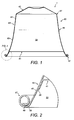
- FIGS 1 and 2 show a first embodiment of capsule 1 according to the present disclosure for use with the beverage preparation machine.
- the capsule 1 will be described in more detail below but may have the general form of a cup-shaped body 40 having a base 42 at one end and a side wall 43 extending from the base 42 towards an opposed end which is closed-off by a lid 41.
- the beverage preparation machine comprises an enclosing member 2 and a capsule holder 20.
- the enclosing member 2 is selectively movable relative to a capsule holder 20 between an open position, to permit insertion of the capsule 1 into the beverage preparation machine, and a closed position, in which the enclosing member sealingly engages the capsule 1 against the capsule holder 20 in a manner that will be described below.
- the enclosing member 2 may be moved between the open and closed positions by means of a conventional mechanism well known in the art.
- the means may involve a mechanical mechanism activated by a manually-movable lever or an automatic or semi-automatic mechanism where movement is driven by a motor.
- the enclosing member 2 may be moved while the capsule holder 20 remains stationary.
- the enclosing member 2 may remain stationary and the capsule holder 20 be moved.
- both the enclosing member 2 and the capsule holder 20 may move during the opening and closing operations.
- the enclosing member 2 and the capsule holder 20 in the closed position together define a receptacle 3 for holding the capsule 1 during a dispensing operation.
- the beverage preparation machine may further comprise other conventional elements which are not illustrated in the accompanying drawings and are well known in the art of beverage preparation machines.
- the beverage preparation machine may comprise either a facility for storing an aqueous medium, such as an internal reservoir, or a facility for connection to an external supply of aqueous medium, such as mains water.
- the aqueous medium will typically be water.
- a pump or equivalent may be provided for supplying the aqueous medium in a pressurised state to the capsule 1.
- the aqueous medium will typically be supplied at a pressure of up to 9 to 14 bar.
- a heater may be provided for heating the aqueous medium to a desired temperature.
- the heater may heat the aqueous medium in the reservoir (where present) or may heat the aqueous medium on-demand as it passes through a conduit or over a thermoblock to the receptacle 3.
- the beverage preparation machine may comprise base piercing means for piercing the base 42 of the capsule 1 to permit the aqueous medium to enter the capsule 1 and interact with the beverage ingredients therein.
- the capsule 1 may be provided with one or more pre-formed openings to allow entry of the aqueous medium from the receptacle 3 into the capsule 1.
- the enclosing member 2 may be of the type described in EP 1700548 comprising an annular element 22 having a leading edge 23 in the form of an annular rim, an inner face 25 facing the receptacle 3 and an outer face 24 facing an exterior.
- the leading edge 23 may be provided with a plurality of grooves as taught in EP 1700548 .
- An upper end (not shown) of the enclosing member 2 may be coupled to a supply of the aqueous medium and may provide a mounting for one or more perforation elements intended to pierce the base 42 of the capsule 1 in use.
- the capsule holder 20 may be of the type described in EP 1700548 comprising relief elements 21 which are designed to tear and perforate the lid 41 of the capsule 1.
- the tearing of the lid 41 may occur due to internal pressurisation of the capsule 1 caused by inflowing aqueous medium.
- the relief elements 21 may have any protruding shape able to cause a partial tearing of the foil member, e.g. pyramids, needles, bumps, cylinders, or elongated ribs.
- the capsule 1 of the first embodiment comprises the cup-shaped body 40 and the lid 41 together enclose a beverage ingredient chamber 50 which may be filled with a beverage ingredient or mixture of beverage ingredients.
- the beverage ingredient may comprise roasted ground coffee.
- the cup-shaped body 40 is made from aluminium or an aluminium alloy. However, other materials may be utilised.
- the cup-shaped body 40 includes the base 42 and the side wall 43. There may be, as illustrated, a geometric discontinuity at the junction between the base 42 and the side wall 43, for example, in the form of a shoulder 57. Alternatively, the base 42 and the side wall 43 may have a smooth geometric transition.
- the cup-shaped body 40 may have a thickness in the range of 80 to 500 microns.
- the thickness of the material may be varied throughout the cup-shaped body 40. In the illustrated example the thickness is 120 microns.
- the side wall 43 may have a flared shape, wherein the diameter of the capsule at the lid end is greater than at the base 42.
- the flared shape may be achieved, for example, by configuring the side wall 43 to have at least a portion that is concavely curved when viewed from the exterior of the capsule 1.
- the whole axial length of the side wall 43 may be flared, for example concavely curved.
- a flared section 45 distal the base 42 may be flared.
- the flared section 45 may extend for a distance of 40 to 80% of a longitudinal height of the capsule, preferably 50 to 70% of the longitudinal height of the capsule. In one example, the flared section 45 extends for a distance of approximately 60% of the longitudinal height of the capsule.
- the side wall 43 comprises a frustoconical section 44 proximate the base 42 and a flared section 45 distal the base 42.
- the capsule 1 may be provided with a rim 47 formed at an end of the cup-shaped body 40 remote from the base 42.
- the rim 47 may be formed integrally with the cup-shaped body 40.
- the rim 47 is formed by a rolled-over portion 48 of the side wall 43.
- the side wall 43 may extend from the base 42 to the rim 47 to define a curved surface without any abrupt angular changes in geometry.
- any transition e.g. at point 46 as shown in Figure 1 , from a flared section 45 to a frustoconical section 44 (or section of another shape, e.g. cylindrical) can be configured to be smooth.
- the capsule 1 may be flangeless except for the optional provision of a rim 47.
- the side wall 43 may not include a flange, as taught for example in EP1700548 which extends substantially perpendicularly from the side wall 43.
- the lid 41 may be formed from aluminium, an aluminium alloy or a laminate containing aluminium.
- the lid 41 may be sealed to the side wall 43 at a location 58 radially inside and above a point of contact, in use, of the leading edge 23 of the enclosing member 2 on the side wall 43.
- the lid 41 may be positioned a distance from the distal end of the side wall 43 which is twice the height of the rim 47.
- the rim 47 may have a height of 1.35 mm. Consequently, the lid 41 may be located 2.7 mm above the-distal end of the side wall 43 (which in this case equates to the lowermost edge of the rim 47).
- the lid 41 may be sealed to the flared section 45 of the side wall 43 and not, as in the prior art, to a flange that extends substantially perpendicularly to the side wall.
- the side wall 43 may comprise a distal portion 59 that extends beyond the location 58 where the lid 41 is sealed to the side wall 43.
- the distal portion 59 may include the rolled-over portion 48 of the rim 47, where present.
- the enclosing member 2 is first moved into the open position and the capsule 1 is inserted into a location in between the capsule holder 20 and the enclosing member 2.
- the capsule 1 may be inserted by gravity or by manual placement or a combination thereof.
- the initial insertion may place the capsule 1 in proximity to the enclosing member 2 such that subsequent movement of the enclosing member 2 carries the capsule 1 therewith into engagement with the capsule holder 20.
- initial insertion may place the capsule 1 in proximity to the capsule holder 20 such that the capsule 1 remains substantially stationary during closure of the enclosing member 2.
- the enclosing member 2 is then closed so as to sealingly engage the enclosing member 2 with the capsule 1. During this step the base 42 of the capsule 1 may be pierced by the perforation elements of the enclosing member 2.
- Pressurised aqueous medium is then flowed into the capsule 1 to produce a beverage from interaction with the beverage ingredients.
- internal pressurisation of the beverage ingredient chamber 50 causes the lid 41 to be deformed outwardly against the relief elements 21 of the capsule holder 20 resulting in at least partial tearing of the lid 41 which opens up an exit path from the capsule 1 for the beverage.
- the beverage is then output for consumption.
- the side wall 43 of the capsule 1 is contacted by the enclosing member 2 to thereby buckle the side wall 43 to produce a valley zone 51 bridging the enclosing member 2.
- the valley zone 51 forms at least one sealing interface between the enclosing member 2 and the side wall 43.
- the point of contact between the leading edge 23 of the annular element 22 and the capsule 1 is on the flared section 45 of the side wall 43.
- the point of contact is at a point on the side wall 43 which is axially spaced from the capsule holder 20 such that there is room for the side wall 43 to deform downwards towards the capsule holder 20 enough to allow for formation of the valley zone 51 before the side wall 43 is nipped against the capsule holder 20.
- the buckling and induced movement of the side wall 43 causes the side wall 43 to undergo plastic deformation.
- the side wall 43 may be plastically drawn over the leading edge 23 of the enclosing member 2 which encourages the material of the side wall 43 to be closely conformed to the grooves of the leading edge 23.
- the valley zone 51 may form a sealing interface with the leading edge 23 of the enclosing member 2.
- the formation of the valley zone 51 may also form a ridge zone 52 which is located outside the enclosing member 2 when it reaches the closed position.
- the ridge zone 52 may comprise an annular feature having an inner wall 54 adjacent the outer face 24 of the annular element 22 and an outer wall 55 facing away from the enclosing member 2.
- An apex 53 of the ridge zone 52 points back towards the base 42 of the capsule 1. Compression of the material of the ridge zone 52 during deformation may cause the apex 53 and/or the inner wall 54 of the ridge zone 52 to be forced inwardly against the outer face 24 to form a sealing interface with the enclosing member 2.
- valley zone 51 may also cause an outward pressure to be exerted by the side wall 43 on the inner face 25 of the enclosing member 2 to form a further sealing interface.
- closure of the enclosing member 2 may compress at least the polymer layer of the laminate material when forming any of the sealing interfaces mentioned above.
- the compression of the polymer layer may aid the conforming of the side wall 43 to the shape of the leading edge 23.
- the polymer layer may aid filling of any gaps arising due to the presence of grooves in the leading edge 23.
- the polymer layer is directed outwardly to be directly contacted by the leading edge 23.
- the hot water passed through the receptacle 3 may act to slightly soften the material of the polymer layer.
- Such softening may lead to further deformation of the side wall 43 under the compressive loading of the enclosing member 2. This effect may help to reinforce the fluid seal between the enclosing member 2 and the capsule 1 by tending to seal up any gaps having hot water leaking there through.
- valley zone 51 will also typically cause a reduction in the longitudinal height, of the capsule 1 relative to its height prior to insertion.
- Figures 7 to 10 shows further variants of capsule 1 according to the present disclosure. Corresponding features of the first embodiment and these variants are denoted by corresponding reference signs. Features of the first embodiment and these variants may be interchanged as desired.
- the side wall 43 Prior to insertion, the side wall 43 is provided with a pre-selected zone in order to promote reliable buckling and formation of the valley zone 51.
- the pre-selected zone may be a circumferential line or band of the side wall 43.
- the pre-selected zone may be configured or treated by altering the rigidity, strength, ductility or other suitable material characteristic of the side wall 43 within (or adjacent to) the pre-selected zone to promote reliable deformation of the side wall during closure of the enclosing member 2.
- the rigidity, strength, ductility or other suitable material characteristic of the side wall 43 may be altered by one or more of work hardening, localised thickening, creasing, scoring or thinning of the material of the side wall.
- a work hardened circumferential band 49 may be formed around the side wall 43.
- the work hardening may be achieved by creasing and uncreasing the side wall material or by other suitable means.
- Alternatives to a work hardened band include the side wall 43 being provided with a zone of increased thickness or alternatively a thinned section of material 49' as shown in Figure 9 ; the side wall 43 being provided with a score line in the side wall 43; or a section of the side wall being subjected to thermal treatment, either before or after drawing.
- the work hardened band 49 is more resistant to bucking than adjacent zones of the side wall 43. Therefore, as shown in Figure 8 , the apex 67 of the ridge zone 63 will reliably be formed at an interface between the work hardened band 49 and the adjacent portion of the side wall 43. A similar mechanism takes place where a localised thickened portion of the side wall 43 is provided. Conversely, where the side wall 43 is weakened locally by, for example, the thinned section 49' or scoring, buckling is promoted at this point. Consequently, the apex 67 of the ridge zone will be reliably be formed by material within the thinned section 49'/at the score line as shown in Figure 10 .
Description
- The present disclosure relates to a beverage preparation system, a capsule and a method for forming a beverage. The beverage preparation system is of the type comprising a beverage preparation machine wherein the capsule is designed for insertion into the beverage preparation machine to permit a pressurised liquid to be flowed through the capsule in order to produce a beverage from interaction with beverage ingredients contained within the capsule.
- Beverage preparation systems which comprise a beverage preparation machine and a capsule containing beverage ingredients are known in the art. One such system is taught in
EP 1700548 , which discloses a capsule comprising a cup-like base body and a closing foil member. The capsule is designed for insertion in a beverage production device in which a liquid under pressure enters the capsule in order to interact with ingredients in the capsule to form a beverage which is output for consumption. The capsule ofEP 1700548 is provided with a dedicated sealing member to prevent a bypass flow of water around the exterior of the capsule in use. The sealing member is in the form of a hollow sealing member on the outer surface of the capsule, for example in the form of a step which is contacted on closure of an enclosing member of the beverage preparation machine.EP1654966 describes a capsule which contains beverage ingredients such as ground coffee, tea or other ingredients and is configured for insertion in a beverage production device in order to have a liquid under pressure have enter the capsule and to interact with the ingredients in the capsule. The capsule comprises a base body and a foil member closing the base body by being attached to a flange-like rim extending from the side wall of the base body of the capsule. The base body of the capsule comprises a resilient sealing member, the sealing member being designed to be in sealing engagement with a bell member of the beverage production device. - The present disclosure provides an alternative capsule which may be used as part of such a beverage preparation system. The capsule may be economical to produce and provide effective sealing in use.
- In a first aspect the present disclosure provides a beverage producing system comprising:
- a capsule containing beverage ingredients; and
- a beverage preparation machine;
- the capsule comprising a cup-shaped body and a lid; the cup-shaped body having a base and a side wall and the lid being sealed to the cup-shaped body;
- the capsule being designed for insertion into the beverage preparation machine to permit a pressurised liquid to be flowed through the capsule in order to produce a beverage from interaction with the beverage ingredients;
- the beverage preparation machine having an enclosing member adapted to be selectively movable between an open position to permit insertion of the capsule into the beverage preparation machine and a closed position in which the enclosing member sealingly engages the capsule;
- wherein the side wall is dimensioned to be contacted by the enclosing member on movement of the enclosing member into the closed position to buckle the side wall to form a valley zone bridging the enclosing member;
- wherein the side wall is adapted such that said valley zone forms at least one sealing interface between the enclosing member and the side wall.
- In a second aspect, the present disclosure provides a capsule for preparing a beverage comprising a cup-shaped body and a lid; the cup-shaped body having a base and a side wall and the lid being sealed to the cup-shaped body;
the capsule being designed for insertion into a beverage preparation machine to permit a pressurised liquid to be flowed through the capsule in order to produce a beverage from interaction with the beverage ingredients;
the beverage preparation machine being of the type having an enclosing member adapted to be selectively movable between an open position to permit insertion of the capsule into the beverage preparation machine and a closed position in which the enclosing member sealingly engages the capsule;
wherein the side wall is dimensioned to be contacted by the enclosing member on movement of the enclosing member into the closed position to buckle the side wall to form a valley zone bridging the enclosing member;
wherein the side wall is adapted such that said valley zone forms at least one sealing interface between the enclosing member and the side wall. - In a third aspect the present disclosure provides a method for preparing a beverage comprising the steps of:
- providing a capsule as described above;
- providing a beverage preparation machine having an enclosing member;
- moving the enclosing member into an open position;
- inserting the capsule into the beverage preparation machine;
- closing the enclosing member so as to sealingly engage the enclosing member with the capsule;
- flowing a pressurised liquid through the capsule to produce a beverage from interaction with the beverage ingredients; and
- outputting the beverage for consumption;
- Advantageously, in the above aspects, buckling of the side wall allows for a relatively large-scale deformation of the side wall to take place to allow formation of the valley zone bridging the enclosing member. This deformation may include folding of the material of the side wall and/or elastic and/or plastic straining of the material of the side wall.
- The above aspects may further comprise one or more of the following features:
The valley zone may form a sealing interface with a leading edge of the enclosing member. - The side wall may be adapted such that during closure of the enclosing member the side wall is plastically drawn over the leading edge of the enclosing member. Advantageously this may allow the side wall to be conformed to the shape of any grooves (or similar) provided in the leading edge.
- The valley zone may be adapted to be nipped against a capsule holder of the beverage preparation machine part.
- The side wall may be adapted to undergo plastic deformation during said buckling.
- The side wall may be adapted such that, following buckling of the side wall, the side wall defines a ridge zone located outside the enclosing member. As above, buckling of the side wall allows for a relatively large-scale deformation of the side wall to take place to allow formation of the ridge zone. This deformation may include folding of the material of the side wall and/or elastic and/or plastic straining of the material of the side wall.
- The ridge zone may be adapted to be forced inwardly against an outer face of the enclosing member to form a sealing interface with the outer face of the enclosing member.
- Advantageously, a sealing interface may be provided with both the leading edge and the outer face of the enclosing member. In addition, the formation of the valley zone may also cause an outward pressure to be exerted by the side wall on the inner face of the enclosing member to form a further sealing interface.
- Prior to insertion, the side wall may have a flared shape.
- Prior to insertion, at least a portion of the side wall may be concavely curved.
- Prior to insertion, the side wall may extend away from the lid at an angle from 45 to 80 degrees.
- The capsule may comprise a rim formed at an end of the cup-shaped body remote from the base.
- The rim may be formed integrally with the cup-shaped body.
- The rim may be formed by a rolled-over portion of the side wall.
- Prior to insertion, the capsule may be flangeless except for the optional provision of a rim.
- Prior to insertion, the side wall may extend from the base to the rim to define a curved surface without any abrupt angular changes in geometry.
- Prior to insertion, the side wall may comprise a pre-selected zone which has been configured or treated to promote a reliable deformation of the side wall. The pre-selected zone may be a circumferential line or band of the side wall. The pre-selected zone may be configured or treated by altering the rigidity, strength, ductility or other suitable material characteristic of the side wall within (or adjacent to) the pre-selected zone to promote reliable deformation of the side wall during closure of the enclosing member. The rigidity, strength, ductility or other suitable material characteristic of the side wall may be altered by one or more of work hardening, localised thickening, creasing, scoring or thinning of the material of the side wall.
- Prior to insertion, the side wall may comprise a frustoconical section proximate the base and a flared section distal the base.
- The flared section may extend for a distance of 40 to 80% of a longitudinal height of the capsule or for a distance of 50 to 70% of the longitudinal height of the capsule or for a distance of approximately 60% of the longitudinal height of the capsule.
- The lid may be sealed to the side wall at a location radially inside a point of contact, in use, of a leading edge of the enclosing member on the side wall. The lid may be sealed to an inner surface of the side wall. The lid may be sealed at a location on the side wall above the point of contact of the leading edge of the enclosing member. The lid may be positioned a distance of from 2.5 to 3.0 mm from the distal end of the side wall. The distance may be selected to be substantially twice the height of the rim, where present. In one example, the rim may have a height of 1.35 mm and the lid may be located 2.7 mm above the distal end of the side wall. These features singularly or in combination may help to ensure that the enclosing member does not bear down on the capsule so as to trap beverage ingredients in between the leading edge and the capsule holder which may have a detrimental effect on the fluid-tightness of the seal.
- The side wall may comprise a distal portion that extends beyond the location where the lid is sealed to the side wall.
- The distal portion of the side wall may form a roll-over edge of the capsule.
- A leading edge of the enclosing member may comprise a plurality of grooves or indentations, and the side wall may be adapted such that the plastic deformation of the side wall conforms the side wall to the grooves or indentations to provide an effective seal.
- The cup-shaped body may be formed from aluminium, an aluminium alloy or a laminate comprising at least one layer formed from aluminium or an aluminium alloy. A lacquer layer may be applied to one or both faces of the cup-shaped body. Alternatively, another, suitably ductile material could be utilised in place of the aluminium or aluminium alloy.
- The aluminium alloy may, for example, be of grade 3005, 3105, 8011 or 8079. Preferably, the aluminium alloy will have an 'O' temper rating.
- The laminate, where used, may comprise a ductile structural layer formed from a material such as aluminium or an aluminium alloy together with a resilient layer formed from a polymer. The laminate may comprise only a single layer of aluminium or aluminium alloy together with a single layer of polymer together with an optional lacquer layer applied to the aluminium or aluminium alloy.
- The polymer layer may, for example, comprise a material selected from the group of: polyvinyl chloride (PVC), polypropylene (PP), low density polyethylene (LDPE), medium density polyethylene (MDPE), high density polyethylene (HDPE), fluorinated ethylene propylene (FEP), polytetrafluoroethylene (PTFE), polyethylene terephthalate (PET), polyamide (PA), ethylene propylene diene monomer (EPDM), polychloroprene or isobutylene.
- The lid may be formed from aluminium, an aluminium alloy or a laminate comprising at least one layer formed from aluminium or an aluminium alloy. Alternatively, another, suitably ductile material could be utilised.
- The cup-shaped body may be formed from a single integral piece of material. The single piece of material may be cold formed to form the shape of the cup-shaped body, including any flared section. A deep-drawing technique may be used to cold form the cup-shaped body. Where the material of the cup-shaped body comprises a laminate with a polymer layer, a warm-drawing technique may be used where the material is subjected to an increased temperature to promote easier deformation of the polymer material but without detrimental effects on the material characteristics of the aluminium layer.
- The cup-shaped body and rim may be integral.
- The cup-shaped body may have a thickness in the range of 80 to 500 microns. In some aspects the thickness may be in the range of 90 to 300 microns. Where the cup-shaped body is formed solely from aluminium or an aluminium alloy (optionally with one or more lacquer layers) a thickness in the range of 80 to 120 microns may be preferred. Where the cup-shaped body is formed from a laminate material comprising a polymer layer a thickness in the range 100 to 500 microns is preferred. The thickness of the material may be varied throughout the cup-shaped body.
- The rim may have an outer diameter of approximately 37 mm.
- Prior to insertion, the capsule may have a height of from 25 to 31 mm. In some aspects the height may be from 29 to 30 mm. Deformation of the capsule during use will tend to reduce the longitudinal height.
- The capsule may form a single-use, disposable element.
- The capsule may contain a beverage ingredient or mixture of beverage ingredients. As a non-limiting example, the beverage ingredient may comprise roasted ground coffee.
- Examples of the present disclosure will now be described in more detail, for exemplary purposes only, with reference to the accompanying drawings, in which:
-
Figure 1 is a cross-sectional view of a first embodiment of capsule according to the present disclosure; -
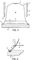
Figure 2 is an enlarged view of a detail ofFigure 1 ; -
Figure 3 is a schematic illustration of the capsule ofFigure 1 together with an enclosing member of a beverage preparation machine; -
Figure 4 is an enlarged view of a detail ofFigure 3 ; -
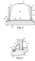
Figure 5 is a schematic illustration of the arrangement ofFigure 3 with the enclosing member in a closed position; -
Figure 6 is an enlarged view of a detail ofFigure 5 ; -
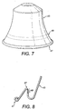
Figure 7 is a perspective view of a further embodiment of capsule according to the present disclosure; -
Figure 8 shows a schematic cross-section through a part of the capsule ofFigure 7 after insertion into a beverage preparation machine; -
Figure 9 is a perspective view of a further embodiment of capsule according to the present disclosure; and -
Figure 10 shows a schematic cross-section through a part of the capsule ofFigure 9 after insertion into a beverage preparation machine. -
Figure 3 shows schematically a part of a beverage preparation system according to the present disclosure. The beverage preparation system comprises a beverage preparation machine and acapsule 1. -
Figures 1 and 2 show a first embodiment ofcapsule 1 according to the present disclosure for use with the beverage preparation machine. Thecapsule 1 will be described in more detail below but may have the general form of a cup-shapedbody 40 having a base 42 at one end and aside wall 43 extending from the base 42 towards an opposed end which is closed-off by alid 41. - As shown in
Figure 3 , the beverage preparation machine comprises an enclosingmember 2 and acapsule holder 20. The enclosingmember 2 is selectively movable relative to acapsule holder 20 between an open position, to permit insertion of thecapsule 1 into the beverage preparation machine, and a closed position, in which the enclosing member sealingly engages thecapsule 1 against thecapsule holder 20 in a manner that will be described below. - The enclosing
member 2 may be moved between the open and closed positions by means of a conventional mechanism well known in the art. For example, the means may involve a mechanical mechanism activated by a manually-movable lever or an automatic or semi-automatic mechanism where movement is driven by a motor. The enclosingmember 2 may be moved while thecapsule holder 20 remains stationary. Alternatively, the enclosingmember 2 may remain stationary and thecapsule holder 20 be moved. In a further alternative arrangement, both the enclosingmember 2 and thecapsule holder 20 may move during the opening and closing operations. - The enclosing
member 2 and thecapsule holder 20 in the closed position together define areceptacle 3 for holding thecapsule 1 during a dispensing operation. - The beverage preparation machine may further comprise other conventional elements which are not illustrated in the accompanying drawings and are well known in the art of beverage preparation machines. For example, the beverage preparation machine may comprise either a facility for storing an aqueous medium, such as an internal reservoir, or a facility for connection to an external supply of aqueous medium, such as mains water. The aqueous medium will typically be water. A pump or equivalent may be provided for supplying the aqueous medium in a pressurised state to the
capsule 1. The aqueous medium will typically be supplied at a pressure of up to 9 to 14 bar. A heater may be provided for heating the aqueous medium to a desired temperature. The heater may heat the aqueous medium in the reservoir (where present) or may heat the aqueous medium on-demand as it passes through a conduit or over a thermoblock to thereceptacle 3. The beverage preparation machine may comprise base piercing means for piercing thebase 42 of thecapsule 1 to permit the aqueous medium to enter thecapsule 1 and interact with the beverage ingredients therein. Alternatively, thecapsule 1 may be provided with one or more pre-formed openings to allow entry of the aqueous medium from thereceptacle 3 into thecapsule 1. - The enclosing
member 2 may be of the type described inEP 1700548 comprising anannular element 22 having a leadingedge 23 in the form of an annular rim, aninner face 25 facing thereceptacle 3 and anouter face 24 facing an exterior. The leadingedge 23 may be provided with a plurality of grooves as taught inEP 1700548 . An upper end (not shown) of the enclosingmember 2 may be coupled to a supply of the aqueous medium and may provide a mounting for one or more perforation elements intended to pierce thebase 42 of thecapsule 1 in use. - The
capsule holder 20 may be of the type described inEP 1700548 comprisingrelief elements 21 which are designed to tear and perforate thelid 41 of thecapsule 1. The tearing of thelid 41 may occur due to internal pressurisation of thecapsule 1 caused by inflowing aqueous medium. Therelief elements 21 may have any protruding shape able to cause a partial tearing of the foil member, e.g. pyramids, needles, bumps, cylinders, or elongated ribs. - As shown in
Figure 1 , thecapsule 1 of the first embodiment comprises the cup-shapedbody 40 and thelid 41 together enclose abeverage ingredient chamber 50 which may be filled with a beverage ingredient or mixture of beverage ingredients. As a non-limiting example, the beverage ingredient may comprise roasted ground coffee. - In the illustrated example, the cup-shaped
body 40 is made from aluminium or an aluminium alloy. However, other materials may be utilised. The cup-shapedbody 40 includes thebase 42 and theside wall 43. There may be, as illustrated, a geometric discontinuity at the junction between the base 42 and theside wall 43, for example, in the form of ashoulder 57. Alternatively, thebase 42 and theside wall 43 may have a smooth geometric transition. - The cup-shaped
body 40 may have a thickness in the range of 80 to 500 microns. The thickness of the material may be varied throughout the cup-shapedbody 40. In the illustrated example the thickness is 120 microns. - The
side wall 43 may have a flared shape, wherein the diameter of the capsule at the lid end is greater than at thebase 42. The flared shape may be achieved, for example, by configuring theside wall 43 to have at least a portion that is concavely curved when viewed from the exterior of thecapsule 1. - The whole axial length of the
side wall 43 may be flared, for example concavely curved. Alternatively, only a flaredsection 45 distal the base 42 may be flared. For example, the flaredsection 45 may extend for a distance of 40 to 80% of a longitudinal height of the capsule, preferably 50 to 70% of the longitudinal height of the capsule. In one example, the flaredsection 45 extends for a distance of approximately 60% of the longitudinal height of the capsule. - In the example illustrated in
Figure 1 , theside wall 43 comprises afrustoconical section 44 proximate thebase 42 and a flaredsection 45 distal thebase 42. - The
capsule 1 may be provided with arim 47 formed at an end of the cup-shapedbody 40 remote from thebase 42. Therim 47 may be formed integrally with the cup-shapedbody 40. In the illustrated example, therim 47 is formed by a rolled-overportion 48 of theside wall 43. - Where a
rim 47 is provided, theside wall 43 may extend from the base 42 to therim 47 to define a curved surface without any abrupt angular changes in geometry. For example, any transition, e.g. atpoint 46 as shown inFigure 1 , from a flaredsection 45 to a frustoconical section 44 (or section of another shape, e.g. cylindrical) can be configured to be smooth. - According to the present disclosure, the
capsule 1 may be flangeless except for the optional provision of arim 47. In other words, theside wall 43 may not include a flange, as taught for example inEP1700548 which extends substantially perpendicularly from theside wall 43. - The
lid 41 may be formed from aluminium, an aluminium alloy or a laminate containing aluminium. Thelid 41 may be sealed to theside wall 43 at alocation 58 radially inside and above a point of contact, in use, of the leadingedge 23 of the enclosingmember 2 on theside wall 43. For example, thelid 41 may be positioned a distance from the distal end of theside wall 43 which is twice the height of therim 47. In the illustrated example, therim 47 may have a height of 1.35 mm. Consequently, thelid 41 may be located 2.7 mm above the-distal end of the side wall 43 (which in this case equates to the lowermost edge of the rim 47). This helps to ensure that the enclosingmember 2 does not bear down on thecapsule 1 so as to trap beverage ingredients in between theleading edge 23 and thecapsule holder 20 which could have a detrimental effect on the fluid-tightness of the seal. To achieve this, thelid 41 may be sealed to the flaredsection 45 of theside wall 43 and not, as in the prior art, to a flange that extends substantially perpendicularly to the side wall. - The
side wall 43 may comprise adistal portion 59 that extends beyond thelocation 58 where thelid 41 is sealed to theside wall 43. Thedistal portion 59 may include the rolled-overportion 48 of therim 47, where present. - In use of the beverage preparation system, the enclosing
member 2 is first moved into the open position and thecapsule 1 is inserted into a location in between thecapsule holder 20 and the enclosingmember 2. Depending on the design of the beverage preparation machine, thecapsule 1 may be inserted by gravity or by manual placement or a combination thereof. In addition, the initial insertion may place thecapsule 1 in proximity to the enclosingmember 2 such that subsequent movement of the enclosingmember 2 carries thecapsule 1 therewith into engagement with thecapsule holder 20. Alternatively, initial insertion may place thecapsule 1 in proximity to thecapsule holder 20 such that thecapsule 1 remains substantially stationary during closure of the enclosingmember 2. - The enclosing
member 2 is then closed so as to sealingly engage the enclosingmember 2 with thecapsule 1. During this step thebase 42 of thecapsule 1 may be pierced by the perforation elements of the enclosingmember 2. - Pressurised aqueous medium is then flowed into the
capsule 1 to produce a beverage from interaction with the beverage ingredients. During this step internal pressurisation of thebeverage ingredient chamber 50 causes thelid 41 to be deformed outwardly against therelief elements 21 of thecapsule holder 20 resulting in at least partial tearing of thelid 41 which opens up an exit path from thecapsule 1 for the beverage. - The beverage is then output for consumption.
- As shown in
Figures 4 and5 , during the step of closing the enclosingmember 2 relative to thecapsule holder 20 theside wall 43 of thecapsule 1 is contacted by the enclosingmember 2 to thereby buckle theside wall 43 to produce avalley zone 51 bridging the enclosingmember 2. Thevalley zone 51 forms at least one sealing interface between the enclosingmember 2 and theside wall 43. - The point of contact between the
leading edge 23 of theannular element 22 and thecapsule 1 is on the flaredsection 45 of theside wall 43. Importantly, the point of contact is at a point on theside wall 43 which is axially spaced from thecapsule holder 20 such that there is room for theside wall 43 to deform downwards towards thecapsule holder 20 enough to allow for formation of thevalley zone 51 before theside wall 43 is nipped against thecapsule holder 20. The buckling and induced movement of theside wall 43 causes theside wall 43 to undergo plastic deformation. In particular, as theside wall 43 is deformed downwards, theside wall 43 may be plastically drawn over the leadingedge 23 of the enclosingmember 2 which encourages the material of theside wall 43 to be closely conformed to the grooves of the leadingedge 23. Thus, thevalley zone 51 may form a sealing interface with the leadingedge 23 of the enclosingmember 2. - The formation of the
valley zone 51 may also form aridge zone 52 which is located outside the enclosingmember 2 when it reaches the closed position. As shown most clearly inFigure 6 , theridge zone 52 may comprise an annular feature having aninner wall 54 adjacent theouter face 24 of theannular element 22 and anouter wall 55 facing away from the enclosingmember 2. An apex 53 of theridge zone 52 points back towards thebase 42 of thecapsule 1. Compression of the material of theridge zone 52 during deformation may cause the apex 53 and/or theinner wall 54 of theridge zone 52 to be forced inwardly against theouter face 24 to form a sealing interface with the enclosingmember 2. - Further, the formation of the
valley zone 51 may also cause an outward pressure to be exerted by theside wall 43 on theinner face 25 of the enclosingmember 2 to form a further sealing interface. - Where the
capsule 1 comprises aside wall 43 formed from a laminate material as discussed above having a polymer layer, closure of the enclosingmember 2 may compress at least the polymer layer of the laminate material when forming any of the sealing interfaces mentioned above. The compression of the polymer layer may aid the conforming of theside wall 43 to the shape of the leadingedge 23. In particular the polymer layer may aid filling of any gaps arising due to the presence of grooves in the leadingedge 23. Preferably, the polymer layer is directed outwardly to be directly contacted by the leadingedge 23. In addition, during use the hot water passed through thereceptacle 3 may act to slightly soften the material of the polymer layer. Such softening may lead to further deformation of theside wall 43 under the compressive loading of the enclosingmember 2. This effect may help to reinforce the fluid seal between the enclosingmember 2 and thecapsule 1 by tending to seal up any gaps having hot water leaking there through. - The formation of the
valley zone 51 will also typically cause a reduction in the longitudinal height, of thecapsule 1 relative to its height prior to insertion. -
Figures 7 to 10 shows further variants ofcapsule 1 according to the present disclosure. Corresponding features of the first embodiment and these variants are denoted by corresponding reference signs. Features of the first embodiment and these variants may be interchanged as desired. - Prior to insertion, the
side wall 43 is provided with a pre-selected zone in order to promote reliable buckling and formation of thevalley zone 51. The pre-selected zone may be a circumferential line or band of theside wall 43. The pre-selected zone may be configured or treated by altering the rigidity, strength, ductility or other suitable material characteristic of theside wall 43 within (or adjacent to) the pre-selected zone to promote reliable deformation of the side wall during closure of the enclosingmember 2. The rigidity, strength, ductility or other suitable material characteristic of theside wall 43 may be altered by one or more of work hardening, localised thickening, creasing, scoring or thinning of the material of the side wall. - For example, as illustrated in
Figure 7 , a work hardenedcircumferential band 49 may be formed around theside wall 43. The work hardening may be achieved by creasing and uncreasing the side wall material or by other suitable means. - Alternatives to a work hardened band include the
side wall 43 being provided with a zone of increased thickness or alternatively a thinned section of material 49' as shown inFigure 9 ; theside wall 43 being provided with a score line in theside wall 43; or a section of the side wall being subjected to thermal treatment, either before or after drawing. - During closure of the enclosing
member 2 the work hardenedband 49 is more resistant to bucking than adjacent zones of theside wall 43. Therefore, as shown inFigure 8 , the apex 67 of the ridge zone 63 will reliably be formed at an interface between the work hardenedband 49 and the adjacent portion of theside wall 43. A similar mechanism takes place where a localised thickened portion of theside wall 43 is provided. Conversely, where theside wall 43 is weakened locally by, for example, the thinned section 49' or scoring, buckling is promoted at this point. Consequently, the apex 67 of the ridge zone will be reliably be formed by material within the thinned section 49'/at the score line as shown inFigure 10 .
wherein said valley zone forms at least one sealing interface between the enclosing member and the side wall.
Claims (19)
- A beverage producing system comprising:a capsule (1) containing beverage ingredients; anda beverage preparation machine;the capsule (1) comprising a cup-shaped body (40) and a lid (41); the cup-shaped body (40) having a base (42)and a side wall (43) and the lid (41) being sealed to the cup-shaped body (40);the capsule (1) being designed for insertion into the beverage preparation machine to permit a pressurised liquid to be flowed through the capsule (1) in order to produce a beverage from interaction with the beverage ingredients;the beverage preparation machine having an enclosing member (2) adapted to be selectively movable between an open position to permit insertion of the capsule (1) into the beverage preparation machine and a closed position in which the enclosing member (2) sealingly engages the capsule (1);characterized in thatthe side wall(43) is dimensioned to be contacted by the enclosing member (2) on movement of the enclosing member (2) into the closed position to buckle the side wall (43) to form a valley zone (51) bridging the enclosing member (2);wherein the side wall (43) is adapted such that said valley zone (51) forms at least one sealing interface between the enclosing member (2) and the side wall (43).
- A beverage producing system as claimed in claim 1, wherein the valley zone (51) forms a sealing interface with a leading edge (23) of the enclosing member (2); and/or
wherein the side wall (43) is adapted such that during closure of the enclosing member (2) the side wall (43) is plastically drawn over the leading edge (23) of the enclosing member (2). - A beverage producing system as claimed in any preceding claim, wherein the valley zone (51) is adapted to be nipped against a capsule holder of the beverage preparation machine part; and/or
wherein the side wall (43) is adapted to undergo plastic deformation during said buckling. - A beverage producing system as claimed in any preceding claim, wherein the side wall (43) is adapted such that, following buckling of the side wall (43), the side wall defines a ridge zone (52) located outside the enclosing member (2); and optionally
wherein the ridge zone (52) is adapted to be forced inwardly against an outer face (24) of the enclosing member (2)to form a sealing interface with the outer face (24) of the enclosing member (2). - A beverage producing system as claimed in any preceding claim, wherein prior to insertion, the side wall (43) has a flared shape; and/or
wherein prior to insertion, at least a portion of the side wall (43) is concavely curved. - A beverage producing system as claimed in any preceding claim, wherein the capsule (1) comprises a rim (47) formed at an end of the cup-shaped body (40) remote from the base; and optionally
wherein the rim (47) is formed integrally with the cup-shaped body (40). - A beverage producing system as claimed in claim 6, wherein the rim (47) is formed by a rolled-over portion of the side wall (43).
- A beverage producing system as claimed in any preceding claim, wherein prior to insertion, the capsule (1) is flangeless except for the optional provision of a rim (47); and/or
wherein prior to insertion, the side wall (43) extends from the base (42) to the rim (47) to define a curved surface without any abrupt angular changes in geometry. - A beverage producing system as claimed in any of claims 1 to 8, wherein prior to insertion, the side wall (43) comprises a pre-selected zone which has been configured or treated to promote a reliable deformation of the side wall (43) .
- A beverage producing system as claimed in any preceding claim, wherein prior to insertion, the side wall (43) comprises a frustoconical section proximate the base (42) and a flared section distal the base (42); and optionally
wherein the flared section extends for a distance of 40 to 80% of a longitudinal height of the capsule (1). - A beverage producing system as claimed in claim 10, wherein the flared section extends for a distance of 50 to 70% of the longitudinal height of the capsule (1); and/or
wherein the flared section extends for a distance of approximately 60% of the longitudinal height of the capsule (1) . - A beverage producing system as claimed in any preceding claim, wherein the lid (41) is sealed to the side wall (43) at a location radially inside a point of contact, in use, of a leading edge (23) of the enclosing member (2) on the side wall (43); and optionally
wherein the side wall (43) comprises a distal portion that extends beyond the location where the lid (41) is sealed to the side wall (43);
wherein the distal portion of the side wall (43) may optionally form a roll-over edge of the capsule (1). - A beverage producing system as claimed in any preceding claim, wherein a leading edge (23) of the enclosing member (2) comprises a plurality of grooves or indentations, and the side wall (43) is adapted such that the plastic deformation of the side wall (43) conforms the side wall (43) to the grooves or indentations to provide an effective seal.
- A beverage producing system as claimed in any preceding claim, wherein the cup-shaped body (40) is formed from aluminium, an aluminium alloy or a laminate comprising at least one layer formed from aluminium or an aluminium alloy; and/or
wherein the lid (41) is formed from aluminium, an aluminium alloy or a laminate comprising at least one layer formed from aluminium or an aluminium alloy. - A beverage producing system as claimed in any preceding claim, wherein the cup-shaped body (40) has a thickness in the range of 80 to 500 microns.
- A capsule (1) for preparing a beverage comprising a cup-shaped body (40) and a lid (41); the cup-shaped body (41) having a base (42) and a side wall (43) and the lid being (41) sealed to the cup-shaped body;
the capsule (1) being designed for insertion into a beverage preparation machine to permit a pressurised liquid to be flowed through the capsule (1) in order to produce a beverage from interaction with the beverage ingredients;
the beverage preparation machine being of the type having an enclosing member (2) adapted to be selectively movable between an open position to permit insertion of the capsule into the beverage preparation machine and a closed position in which the enclosing member (2) sealingly engages the capsule (1); characterized in that the side wall is (43) dimensioned to be contacted by the enclosing member (2) on movement of the enclosing member (2) into the closed position to buckle the side wall (43) to form a valley zone (51) bridging the enclosing member (2);
wherein the side wall (43)is adapted such that said valley zone (51) forms at least one sealing interface between the enclosing member (2) and the side wall (43). - A capsule as claimed in claim 16, wherein the cup-shaped body is formed from aluminium, an aluminium alloy or a laminate comprising at least one layer formed from aluminium or an aluminium alloy; and/or
wherein the lid is formed from aluminium, an aluminium alloy or a laminate comprising at least one layer formed from aluminium or an aluminium alloy. - A capsule as claimed in any of claims 16 to 17, wherein the cup-shaped body has a thickness in the range of 80 to 500 microns.
- A method for preparing a beverage comprising the steps of:- providing a capsule (1) as claimed in any of claims 16 to 18;- providing a beverage preparation machine having an enclosing member (2);- moving the enclosing member (2) into an open position;- inserting the capsule (1) into the beverage preparation machine;- closing the enclosing member (2) so as to sealingly engage the enclosing member (2) with the capsule (1);- flowing a pressurised liquid through the capsule (1) to produce a beverage from interaction with the beverage ingredients; and- outputting the beverage for consumption;wherein on closure of the enclosing member (2) the side wall (43) of the capsule is contacted by the enclosing member (2) to thereby buckle the side wall (43) to produce a valley zone (51) bridging the enclosing member (2);
wherein said valley zone (51) forms at least one sealing interface between the enclosing member (2) and the side wall (43).
Priority Applications (1)
| Application Number | Priority Date | Filing Date | Title |
|---|---|---|---|
| PL14730191T PL2996966T3 (en) | 2013-05-17 | 2014-05-16 | A beverage preparation system, a capsule and a method for forming a beverage |
Applications Claiming Priority (2)
| Application Number | Priority Date | Filing Date | Title |
|---|---|---|---|
| GBGB1308927.1A GB201308927D0 (en) | 2013-05-17 | 2013-05-17 | A beverage preparation system, a capsule and a method for forming a beverage |
| PCT/IB2014/000852 WO2014184651A1 (en) | 2013-05-17 | 2014-05-16 | A beverage preparation system, a capsule and a method for forming a beverage |
Publications (2)
| Publication Number | Publication Date |
|---|---|
| EP2996966A1 EP2996966A1 (en) | 2016-03-23 |
| EP2996966B1 true EP2996966B1 (en) | 2021-01-06 |
Family
ID=48746927
Family Applications (1)
| Application Number | Title | Priority Date | Filing Date |
|---|---|---|---|
| EP14730191.5A Active EP2996966B1 (en) | 2013-05-17 | 2014-05-16 | A beverage preparation system, a capsule and a method for forming a beverage |
Country Status (16)
| Country | Link |
|---|---|
| US (1) | US10730691B2 (en) |
| EP (1) | EP2996966B1 (en) |
| JP (1) | JP6134864B2 (en) |
| KR (1) | KR101900546B1 (en) |
| CN (1) | CN105189310B (en) |
| AU (1) | AU2014266920B2 (en) |
| BR (1) | BR112015028378B1 (en) |
| CA (1) | CA2901561C (en) |
| DK (1) | DK2996966T3 (en) |
| ES (1) | ES2856003T3 (en) |
| GB (1) | GB201308927D0 (en) |
| HK (1) | HK1222831A1 (en) |
| PL (1) | PL2996966T3 (en) |
| PT (1) | PT2996966T (en) |
| RU (1) | RU2628906C2 (en) |
| WO (1) | WO2014184651A1 (en) |
Families Citing this family (29)
| Publication number | Priority date | Publication date | Assignee | Title |
|---|---|---|---|---|
| CN103476686B (en) * | 2010-07-22 | 2016-08-31 | K-Fee系统股份有限公司 | There is the distribution capsule of identifier |
| GB201308927D0 (en) | 2013-05-17 | 2013-07-03 | Kraft Foods R & D Inc | A beverage preparation system, a capsule and a method for forming a beverage |
| AU2014266921C1 (en) | 2013-05-17 | 2018-01-25 | Koninklijke Douwe Egberts B.V. | A beverage preparation system, a capsule and a method for forming a beverage |
| JP6811091B2 (en) | 2014-01-03 | 2021-01-13 | コーニンクラケ ダウ エグバート ビー.ブイ. | Replaceable supply packs, dispensers, pump assemblies, and manufacturing methods for beverage preparation equipment |
| US10624499B2 (en) | 2014-07-30 | 2020-04-21 | North American Robotics Corporation | Systems and methods for pressure control in automated blending devices |
| EP3174442A4 (en) | 2014-07-30 | 2018-05-30 | North American Robotics Corporation | Automated food processing system and method |
| USD752971S1 (en) * | 2015-03-24 | 2016-04-05 | North American Robotics Corporation | Food container |
| US9629503B2 (en) | 2014-07-30 | 2017-04-25 | North American Robotics Corporation | Blending container for use with blending apparatus |
| GB201420262D0 (en) | 2014-11-14 | 2014-12-31 | Kraft Foods R & D Inc | A method of forming a cup-shaped body for a beverage capsule |
| KR20180008596A (en) | 2015-05-15 | 2018-01-24 | 코닌클리케 도우베 에그베르츠 비.브이. | Capsules, systems for making drinking beverages from such capsules, and methods of using such capsules in beverage making devices |
| JP6978943B2 (en) * | 2015-05-15 | 2021-12-08 | コーニンクラケ ダウ エグバート ビー.ブイ. | Capsules, systems for preparing drinkable beverages from such capsules, and how to use such capsules in beverage preparation equipment. |
| PL3134331T3 (en) | 2015-05-15 | 2018-12-31 | Koninklijke Douwe Egberts B.V. | A capsule, a system for preparing a potable beverage from such a capsule and use of such a capsule in a beverage preparation device. |
| AU2016264683B2 (en) * | 2015-05-15 | 2021-07-29 | Koninklijke Douwe Egberts B.V. | A capsule, a system for preparing a potable beverage from such a capsule and use of such a capsule in a beverage preparation device |
| CH711079B1 (en) * | 2015-05-15 | 2017-08-15 | Douwe Egberts Bv | Capsule, system for preparing a beverage from such a capsule and use of such a capsule in a beverage preparation device. |
| RU2020134017A (en) | 2015-05-15 | 2020-11-20 | Конинклейке Дауве Егбертс Б.В. | CAPSULE SYSTEM FOR PREPARING A DRINKABLE BEVERAGE FROM A LIKE CAPSULE AND APPLYING A LIKE CAPSULE IN THE BEVERAGE PREPARATION |
| MX2017014647A (en) | 2015-05-15 | 2018-01-23 | Douwe Egberts Bv | A capsule, a system for preparing a potable beverage from such a capsule and use of such a capsule in a beverage preparation device. |
| EP3368447B1 (en) | 2015-10-27 | 2020-04-22 | Koninklijke Douwe Egberts B.V. | Capsule, system and method for preparing a beverage |
| NL2016780B1 (en) | 2016-05-13 | 2017-11-16 | Douwe Egberts Bv | A capsule, a system for preparing a potable beverage from such a capsule and use of such a capsule in a beverage preparation device |
| NL2016779B1 (en) | 2016-05-13 | 2017-11-16 | Douwe Egberts Bv | A capsule and a system for preparing a potable beverage from such a capsule |
| NL2019254B9 (en) | 2016-10-07 | 2018-09-10 | Douwe Egberts Bv | A capsule, a system for preparing a potable beverage from such a capsule and use of such a capsule in a beverage preparation device |
| KR20180043876A (en) * | 2016-10-20 | 2018-05-02 | 주식회사 자로 | Black soybean capsule |
| CN109922668B (en) | 2016-11-09 | 2023-03-31 | 百事可乐公司 | Carbonated beverage preparation machine, method and system |
| NL2019253B1 (en) | 2017-07-14 | 2019-01-28 | Douwe Egberts Bv | Assembly of a capsule and a brew chamber, brew chamber, beverage preparation machine, capsule and use of a capsule. |
| WO2020020756A1 (en) * | 2018-07-27 | 2020-01-30 | K-Fee System Gmbh | Method for producing a portion capsule for preparing a beverage in a beverage production machine, portion capsule, and method for producing a beverage with a beverage production machine and a portion capsule |
| TW202023919A (en) * | 2018-09-14 | 2020-07-01 | 瑞士商雀巢製品股份有限公司 | Capsule for beverage preparation with integrally formed sealing member |
| EP3702298A1 (en) | 2019-03-01 | 2020-09-02 | Delica AG | Capsule and system for for preparing a liquid food |
| EP3702061B1 (en) | 2019-03-01 | 2023-09-27 | Adval Tech Holding AG | Method for manufacturing conical metal objects |
| NL2022931B1 (en) * | 2019-04-11 | 2020-10-20 | Stas I P B V | Preparation system for extracting product contained in a capsule |
| EP4037996A1 (en) * | 2019-10-02 | 2022-08-10 | Novelis, Inc. | Aluminum flat rolled products with high recycled content for light gauge packaging solutions and related methods |
Citations (31)
| Publication number | Priority date | Publication date | Assignee | Title |
|---|---|---|---|---|
| FR2617389A1 (en) | 1987-06-30 | 1989-01-06 | Desaltera | FILTER CARTRIDGE AND MACHINE FOR THE PREPARATION OF AN EXPRESS BEVERAGE |
| EP0468079A1 (en) | 1990-07-27 | 1992-01-29 | Societe Des Produits Nestle S.A. | Closed cartridge for making a beverage, process and device for manufacturing such a cartridge |
| EP1369069A2 (en) * | 2002-06-07 | 2003-12-10 | SGL Italia S.r.l. | Method and device for piercing a sealed capsule on a coffee machine |
| WO2006045537A1 (en) * | 2004-10-25 | 2006-05-04 | Nestec S.A. | Capsule with biasing sealing member |
| EP1654966A1 (en) * | 2004-10-25 | 2006-05-10 | Nestec S.A. | Capsule with sealing means |
| EP1849715A1 (en) * | 2006-04-24 | 2007-10-31 | Nestec S.A. | Capsule for preparation of a beverage with a sealing member attached thereto and method of producing the same |
| WO2007137974A2 (en) | 2006-05-29 | 2007-12-06 | Nestec S.A. | Coffee capsule with a deformable sealing element |
| EP2100824A1 (en) * | 2008-03-12 | 2009-09-16 | Nestec S.A. | Capsule with flow control and filtering member |
| WO2009115474A1 (en) | 2008-03-20 | 2009-09-24 | Nestec S.A. | Beverage production device for producing a beverage from a single-use capsule |
| DE102008014758A1 (en) | 2008-03-18 | 2009-10-08 | Inde Plastik Betriebsgesellschaft Mbh | Closed portion package for soluble coffee substance for espresso machine, has side wall provided with carrier section, and inner section, which is formed of flexible plastic foil deformable under pressure and laminated on carrier section |
| EP2151313A1 (en) * | 2008-07-15 | 2010-02-10 | Nestec S.A. | Method for applying a liquid seal rubber to a capsule |
| WO2010076048A1 (en) * | 2009-01-05 | 2010-07-08 | Nestec S.A. | Capsule with flow control and filtering member |
| WO2010116284A2 (en) | 2009-04-08 | 2010-10-14 | Ethical Coffee Company Sa | Brewing device and capsule for preparing a drink |
| WO2010128844A1 (en) * | 2009-06-17 | 2010-11-11 | Sara Lee/De N.V. | Capsule for containing beverage ingredients |
| WO2011010263A1 (en) * | 2009-07-24 | 2011-01-27 | Ethical Coffee Company Sa | Device for preparing a beverage extracted from a capsule |
| EP2284101A1 (en) | 2009-08-05 | 2011-02-16 | Nestec S.A. | Capsule with relief-shaped sealing member |
| EP2284100A1 (en) * | 2009-08-05 | 2011-02-16 | Nestec S.A. | Capsule with dedicated sealing means |
| ES1077395U (en) | 2012-06-26 | 2012-07-16 | Productos Solubles S.A. | Capsule for preparing infusions |
| WO2012104760A1 (en) * | 2011-01-31 | 2012-08-09 | Sarong Societa' Per Azioni | Capsules and dispensing machine |
| EP2489609A1 (en) * | 2011-02-17 | 2012-08-22 | E.T.I. S.r.l. | A capsule for containing a preparation for a hot drink |
| WO2012118367A1 (en) * | 2011-03-03 | 2012-09-07 | Biserkon Holdings Ltd. | Capsule, device and method for preparing a beverage by extraction |
| WO2012127233A2 (en) * | 2011-03-23 | 2012-09-27 | Kraft Foods R&D, Inc. | A capsule and a system for, and a method of, preparing a beverage |
| ES1078818U (en) | 2013-02-22 | 2013-03-12 | Productos Solubles S.A. | Capsule to prepare infusions (Machine-translation by Google Translate, not legally binding) |
| WO2013132435A1 (en) * | 2012-03-05 | 2013-09-12 | Macchiavelli S.R.L. | Capsule for infusion products |
| WO2014012779A2 (en) * | 2012-07-16 | 2014-01-23 | Tuttoespresso S.R.L. | Capsule with improved sealing element |
| EP2712824A1 (en) * | 2012-09-26 | 2014-04-02 | Alice Allison SA | Portion package for espresso machines |
| EP2721971A1 (en) * | 2012-10-17 | 2014-04-23 | Stas I.P. B.V. | Product container, as well as assembly of a product container and a tool |
| EP2757056A1 (en) * | 2013-01-17 | 2014-07-23 | Alice Allison SA | Capsule part for a coffee capsule |
| WO2014118812A1 (en) * | 2013-01-29 | 2014-08-07 | Bisio Progetti S.P.A. | Capsule for preparing infusion beverages and process for operating said capsule |
| EP2892400A1 (en) * | 2012-09-07 | 2015-07-15 | Nestec S.A. | Capsule storage |
| WO2020053075A1 (en) | 2018-09-14 | 2020-03-19 | Société des Produits Nestlé S.A. | Capsule for beverage preparation with integrally formed sealing member |
Family Cites Families (75)
| Publication number | Priority date | Publication date | Assignee | Title |
|---|---|---|---|---|
| US3233813A (en) | 1963-07-31 | 1966-02-08 | Reynolds Metals Co | Pie plate receptacle with stepped flange |
| US3987720A (en) | 1975-09-15 | 1976-10-26 | The Raymond Lee Organization, Inc. | No drip pie plate |
| GB2104049B (en) | 1981-02-27 | 1985-06-19 | Nestle Sa | Sealing process for filled containers |
| US4762514A (en) | 1985-11-01 | 1988-08-09 | Fujimori Kogyo Co., Ltd. | Method of making beverage packaging bag |
| US5178293A (en) | 1986-04-08 | 1993-01-12 | Idemitsu Petrochemical Co., Ltd. | Easily-openable packaging container |
| DE3641127A1 (en) | 1986-12-02 | 1988-06-16 | Lentia Gmbh | Process for producing curved parts of metal-thermoplastic composites |
| US4865217A (en) | 1987-08-31 | 1989-09-12 | Sumitomo Bakelite Company, Limited | Easily openable sealed container |
| CA2007748C (en) | 1989-08-31 | 1996-01-02 | Eiji Tamura | Food packaging container |
| FR2660220B1 (en) | 1990-04-03 | 1995-02-24 | Lorraine Laminage | PROCESS AND DEVICE FOR FORMING A RELIEF PART ON A SHEET OF SHEET AND PRODUCT OBTAINED ACCORDING TO THIS PROCESS. |
| DE69015629T2 (en) | 1990-07-27 | 1995-05-04 | Nestle Sa | Process for extracting open coffee capsules, coffee capsule and extraction device for carrying out this method. |
| US5897899A (en) | 1991-05-08 | 1999-04-27 | Nestec S.A. | Cartridges containing substances for beverage preparation |
| AU1505192A (en) | 1991-05-10 | 1992-11-12 | Societe Des Produits Nestle S.A. | Sealed cartridge for the prepartion of a beverage |
| ZA924490B (en) | 1991-07-05 | 1993-03-31 | Nestle Sa | A flexible package with a stiffening element and a process for its production |
| ATE146749T1 (en) | 1991-07-05 | 1997-01-15 | Nestle Sa | STURDY COFFEE CASSETTE AND METHOD FOR PRODUCING SAME |
| DE69105494T2 (en) | 1991-07-05 | 1995-04-06 | Nestle Sa | Flexible open packaging and method of making the same. |
| IL110837A (en) | 1993-09-10 | 2001-03-19 | Plastipak Packaging Inc | Polyethylene terephthalate multi-layer preform used for plastic blow molding and method for making the preform |
| IT1285563B1 (en) | 1996-02-13 | 1998-06-18 | Pelliconi & C Spa | LID, IN PARTICULAR FOR CONTAINERS OF FOOD PRODUCTS AND PROCEDURE FOR ITS REALIZATION |
| ZA985765B (en) | 1997-07-02 | 1999-08-04 | Merck & Co Inc | Polymorphic form of a tachykinin receptor antagonist. |
| ATE263086T1 (en) | 2000-09-26 | 2004-04-15 | Nestle Sa | PACKAGING FOR DRINK PREPARATION WITH EXTRACTION UNDER PRESSURE |
| US6371335B1 (en) | 2000-12-07 | 2002-04-16 | Sealright Co., Inc. | Folded end construction for food sauce dispensing cartridges |
| US7063238B2 (en) | 2001-06-29 | 2006-06-20 | Robert Hale | Cartridge ejector for a beverage dispensing machine |
| ATE325756T1 (en) | 2002-03-14 | 2006-06-15 | Robert Hale | CARTRIDGE FOR BEVERAGES, METHOD FOR PRODUCING THE SAME AND FILTER THEREOF |
| GB2397509B (en) | 2003-01-24 | 2005-11-23 | Kraft Foods R & D Inc | A system for the preparation of beverages |
| GB2397497B (en) | 2003-01-24 | 2005-11-02 | Kraft Foods R & D Inc | Cartridge and method for the preparation of beverages |
| EP1687213A2 (en) | 2003-11-11 | 2006-08-09 | Graphic Packaging International, Inc. | Nestable container with uniform stacking features |
| ITCO20030012U1 (en) | 2003-12-29 | 2005-06-30 | Ilenaig Sas Di Giannelli Giuseppe | CAPSULE CONDENSED BEVERAGES |
| US7556191B2 (en) | 2004-05-18 | 2009-07-07 | Evergreen Packaging, Inc. | Rupturable opening for sealed container |
| US7381885B2 (en) * | 2004-07-14 | 2008-06-03 | Yamaha Corporation | Electronic percussion instrument and percussion tone control program |
| DE602005013959D1 (en) | 2005-09-21 | 2009-05-28 | Illycaffe Spa | Capsule containing a substance for extracting a beverage |
| PT1839543E (en) | 2006-03-31 | 2008-07-23 | Nestec Sa | Capsule with outer sealing material pressurized by a fluid |
| US8176714B2 (en) | 2006-04-24 | 2012-05-15 | Nestec S.A. | Capsule for preparing a beverage with a sealing member for water tightness attached thereto and method of producing the same |
| US7947316B2 (en) * | 2006-08-04 | 2011-05-24 | The Coca-Cola Company | Pod for dispersible materials |
| PL1944248T3 (en) | 2007-01-15 | 2018-05-30 | Swiss Caffe Asia Ltd. | Capsule, means for penetrating the bottom of a capsule and device for preparing a drink |
| US7910145B2 (en) | 2007-05-31 | 2011-03-22 | Marco Reati | Precharged ground coffee capsule, method for its production and apparatus for implementing said method |
| EP2152607B1 (en) | 2007-06-05 | 2012-01-11 | Nestec S.A. | Single-use capsule for preparing a food liquid by centrifugation |
| US9226611B2 (en) | 2007-06-05 | 2016-01-05 | Nestec S.A. | Capsule system, device and method for preparing a food liquid contained in a receptacle by centrifugation |
| WO2008155749A1 (en) | 2007-06-18 | 2008-12-24 | Pt. Alcan Packaging Flexipack | Laminate packaging opening device |
| US20100001530A1 (en) * | 2008-06-03 | 2010-01-07 | Chang Nelson N S | "Sandwich" multiple hydro turbine power driver technology |
| EP2165937A1 (en) | 2008-09-23 | 2010-03-24 | Nestec S.A. | Bicoloured aluminium container and process for producing said container |
| JP4399022B1 (en) | 2008-10-21 | 2010-01-13 | 泉化成工業株式会社 | Method for forming stretched synthetic resin sheet |
| RU2508895C2 (en) | 2008-12-03 | 2014-03-10 | Нестек С.А. | Capsule for preparing beverage by method of centrifugation |
| JP5406306B2 (en) | 2008-12-09 | 2014-02-05 | ネステク ソシエテ アノニム | Capsule for preparing a beverage by centrifugation in a beverage preparation device and device adapted therefor |
| EP2210827B1 (en) | 2009-01-22 | 2012-09-26 | Nestec S.A. | Capsule with delaminatable injection means |
| CN102292271A (en) | 2009-01-23 | 2011-12-21 | 艾斯克咖啡有限公司 | Capsule for preparing a drink |
| EP2364930B1 (en) | 2009-03-19 | 2018-12-05 | Nestec S.A. | Capsule for preparing coffee in a device comprising a cartridge holder with relief and recessed elements |
| EP2592021B1 (en) | 2009-08-19 | 2015-03-04 | Nestec S.A. | Capsule for the preparation of a coffee extract having a structure facilitating perforation for injection of water |
| KR20120095778A (en) | 2009-11-19 | 2012-08-29 | 네스텍 소시에테아노님 | Capsule and method for preparing a beverage such as coffee from said capsule |
| ITGE20100009A1 (en) | 2010-01-26 | 2010-04-27 | Marco Reati | PRE-PACKAGING OF COFFEE POWDER. |
| PT2528485E (en) | 2010-01-29 | 2015-10-20 | Nestec Sa | Capsule and system for preparing a beverage by centrifugation in a beverage production device |
| ES2426266T3 (en) * | 2010-06-11 | 2013-10-22 | Alain Frydman | Capsule with rupture onset zone |
| AU2012210723A1 (en) | 2011-01-24 | 2013-07-25 | Nestec S.A. | Capsule and method for the preparation of a beverage by centrifugation |
| JP5833672B2 (en) | 2011-01-28 | 2015-12-16 | ネステク ソシエテ アノニム | Beverage production system and capsule with pressing ring |
| FR2972180B3 (en) | 2011-03-04 | 2013-04-12 | Laurent Lombart | KIT OR ASSEMBLY FOR FORMING FILLABLE CAPSULES FOR THE PREPARATION OF INFUSIONS |
| PT2683626T (en) | 2011-03-07 | 2018-04-04 | Ethical Coffee Company Sa | Capsule for preparing a beverage |
| EP2562101A1 (en) | 2011-08-22 | 2013-02-27 | Nestec S.A. | A capsule for use in a beverage preparation machine |
| NL2007417C2 (en) | 2011-09-14 | 2013-03-18 | Ahold Coffee Company B V | Capsule, and method of producing it. |
| JP2014527891A (en) | 2011-09-28 | 2014-10-23 | トゥットエスプレッソ エス.アール.エル.Tuttoespresso S.R.L. | Beverage capsule with sealing element |
| ITMI20111847A1 (en) | 2011-10-10 | 2013-04-11 | Goglio Spa | CARTRIDGE FOR COFFEE AND SOLUBLE PRODUCTS IN GENERAL |
| CN103050641B (en) | 2011-10-14 | 2016-03-02 | 乐金显示有限公司 | The display panel of organic luminescent device and this device of use |
| ES1075815Y (en) | 2011-10-25 | 2012-03-08 | Inventos Para Sist S Vending S L | MONODOSIS CAPSULE FOR ESPRESSO COFFEE MACHINES |
| DE102011121647A1 (en) | 2011-12-19 | 2013-06-20 | riha WeserGold Getränke GmbH & Co. KG | Beverage container with drinking straw piercing opening |
| DK2794427T4 (en) | 2011-12-21 | 2021-11-01 | Delica Ag | Capsule, capsule body, method and system for preparing a beverage |
| US20130224340A1 (en) | 2012-02-27 | 2013-08-29 | Hanan BenDavid | Optimal extraction rate coffee capsule with effective seal for diverse group heads |
| US8986763B2 (en) | 2012-02-27 | 2015-03-24 | Rialto Coffee Company Ltd. | Optimal extraction rate coffee capsule with effective seal for diverse group heads |
| ITVR20120043A1 (en) | 2012-03-14 | 2013-09-15 | Coffee Star S A | DRINK PRODUCTION SYSTEM |
| WO2013157924A1 (en) | 2012-04-17 | 2013-10-24 | Biserkon Holdings Ltd. | Capsule and device for preparing beverages and method for manufacturing a capsule |
| RU2633241C2 (en) | 2012-07-16 | 2017-10-11 | Туттоэспрессо С.Р.Л. | Capsule and system for preparation of beverages with adaptive sealing element |
| JP6159404B2 (en) * | 2012-08-24 | 2017-07-05 | ネステク ソシエテ アノニム | Capsules for use in food preparation machines |
| DE112013002899A5 (en) | 2012-10-29 | 2015-08-06 | Cstec Gmbh | Capsule for holding a brewing product such as coffee, tea and the like, as well as methods for closing such a capsule |
| EP2757055A1 (en) | 2013-01-17 | 2014-07-23 | Tuttoespresso S.r.l. | Capsule and system for beverage preparation |
| GB201308929D0 (en) | 2013-05-17 | 2013-07-03 | Kraft Foods R & D Inc | A beverage preparation system, a capsule and a method for forming a beverage |
| AU2014266921C1 (en) | 2013-05-17 | 2018-01-25 | Koninklijke Douwe Egberts B.V. | A beverage preparation system, a capsule and a method for forming a beverage |
| GB201308927D0 (en) | 2013-05-17 | 2013-07-03 | Kraft Foods R & D Inc | A beverage preparation system, a capsule and a method for forming a beverage |
| WO2015101394A1 (en) | 2013-12-30 | 2015-07-09 | Landmax Ltd | Capsule for a beverage preparation with deformable sealing element |
| GB201420262D0 (en) | 2014-11-14 | 2014-12-31 | Kraft Foods R & D Inc | A method of forming a cup-shaped body for a beverage capsule |
-
2013
- 2013-05-17 GB GBGB1308927.1A patent/GB201308927D0/en not_active Ceased
-
2014
- 2014-05-16 CN CN201480026631.9A patent/CN105189310B/en active Active
- 2014-05-16 RU RU2015148011A patent/RU2628906C2/en active
- 2014-05-16 US US14/786,520 patent/US10730691B2/en active Active
- 2014-05-16 ES ES14730191T patent/ES2856003T3/en active Active
- 2014-05-16 JP JP2016512434A patent/JP6134864B2/en active Active
- 2014-05-16 BR BR112015028378-0A patent/BR112015028378B1/en active IP Right Grant
- 2014-05-16 PT PT147301915T patent/PT2996966T/en unknown
- 2014-05-16 CA CA2901561A patent/CA2901561C/en active Active
- 2014-05-16 PL PL14730191T patent/PL2996966T3/en unknown
- 2014-05-16 DK DK14730191.5T patent/DK2996966T3/en active
- 2014-05-16 WO PCT/IB2014/000852 patent/WO2014184651A1/en active Application Filing
- 2014-05-16 AU AU2014266920A patent/AU2014266920B2/en active Active
- 2014-05-16 KR KR1020157031884A patent/KR101900546B1/en active IP Right Grant
- 2014-05-16 EP EP14730191.5A patent/EP2996966B1/en active Active
-
2016
- 2016-09-22 HK HK16111140.8A patent/HK1222831A1/en unknown
Patent Citations (32)
| Publication number | Priority date | Publication date | Assignee | Title |
|---|---|---|---|---|
| FR2617389A1 (en) | 1987-06-30 | 1989-01-06 | Desaltera | FILTER CARTRIDGE AND MACHINE FOR THE PREPARATION OF AN EXPRESS BEVERAGE |
| EP0468079A1 (en) | 1990-07-27 | 1992-01-29 | Societe Des Produits Nestle S.A. | Closed cartridge for making a beverage, process and device for manufacturing such a cartridge |
| EP1369069A2 (en) * | 2002-06-07 | 2003-12-10 | SGL Italia S.r.l. | Method and device for piercing a sealed capsule on a coffee machine |
| WO2006045537A1 (en) * | 2004-10-25 | 2006-05-04 | Nestec S.A. | Capsule with biasing sealing member |
| EP1654966A1 (en) * | 2004-10-25 | 2006-05-10 | Nestec S.A. | Capsule with sealing means |
| EP1849715A1 (en) * | 2006-04-24 | 2007-10-31 | Nestec S.A. | Capsule for preparation of a beverage with a sealing member attached thereto and method of producing the same |
| WO2007137974A2 (en) | 2006-05-29 | 2007-12-06 | Nestec S.A. | Coffee capsule with a deformable sealing element |
| EP2100824A1 (en) * | 2008-03-12 | 2009-09-16 | Nestec S.A. | Capsule with flow control and filtering member |
| DE102008014758A1 (en) | 2008-03-18 | 2009-10-08 | Inde Plastik Betriebsgesellschaft Mbh | Closed portion package for soluble coffee substance for espresso machine, has side wall provided with carrier section, and inner section, which is formed of flexible plastic foil deformable under pressure and laminated on carrier section |
| WO2009115474A1 (en) | 2008-03-20 | 2009-09-24 | Nestec S.A. | Beverage production device for producing a beverage from a single-use capsule |
| EP2151313A1 (en) * | 2008-07-15 | 2010-02-10 | Nestec S.A. | Method for applying a liquid seal rubber to a capsule |
| WO2010076048A1 (en) * | 2009-01-05 | 2010-07-08 | Nestec S.A. | Capsule with flow control and filtering member |
| WO2010116284A2 (en) | 2009-04-08 | 2010-10-14 | Ethical Coffee Company Sa | Brewing device and capsule for preparing a drink |
| WO2010128844A1 (en) * | 2009-06-17 | 2010-11-11 | Sara Lee/De N.V. | Capsule for containing beverage ingredients |
| WO2011010263A1 (en) * | 2009-07-24 | 2011-01-27 | Ethical Coffee Company Sa | Device for preparing a beverage extracted from a capsule |
| EP2284100A1 (en) * | 2009-08-05 | 2011-02-16 | Nestec S.A. | Capsule with dedicated sealing means |
| EP2284101A1 (en) | 2009-08-05 | 2011-02-16 | Nestec S.A. | Capsule with relief-shaped sealing member |
| WO2012104760A1 (en) * | 2011-01-31 | 2012-08-09 | Sarong Societa' Per Azioni | Capsules and dispensing machine |
| EP2489609A1 (en) * | 2011-02-17 | 2012-08-22 | E.T.I. S.r.l. | A capsule for containing a preparation for a hot drink |
| WO2012118367A1 (en) * | 2011-03-03 | 2012-09-07 | Biserkon Holdings Ltd. | Capsule, device and method for preparing a beverage by extraction |
| WO2012127233A2 (en) * | 2011-03-23 | 2012-09-27 | Kraft Foods R&D, Inc. | A capsule and a system for, and a method of, preparing a beverage |
| WO2013132435A1 (en) * | 2012-03-05 | 2013-09-12 | Macchiavelli S.R.L. | Capsule for infusion products |
| ES1077395U (en) | 2012-06-26 | 2012-07-16 | Productos Solubles S.A. | Capsule for preparing infusions |
| WO2014012779A2 (en) * | 2012-07-16 | 2014-01-23 | Tuttoespresso S.R.L. | Capsule with improved sealing element |
| EP2892400A1 (en) * | 2012-09-07 | 2015-07-15 | Nestec S.A. | Capsule storage |
| EP2712824A1 (en) * | 2012-09-26 | 2014-04-02 | Alice Allison SA | Portion package for espresso machines |
| EP2721971A1 (en) * | 2012-10-17 | 2014-04-23 | Stas I.P. B.V. | Product container, as well as assembly of a product container and a tool |
| EP2757056A1 (en) * | 2013-01-17 | 2014-07-23 | Alice Allison SA | Capsule part for a coffee capsule |
| WO2014118812A1 (en) * | 2013-01-29 | 2014-08-07 | Bisio Progetti S.P.A. | Capsule for preparing infusion beverages and process for operating said capsule |
| ES1078818U (en) | 2013-02-22 | 2013-03-12 | Productos Solubles S.A. | Capsule to prepare infusions (Machine-translation by Google Translate, not legally binding) |
| EP2960181A1 (en) * | 2013-02-22 | 2015-12-30 | Productos Solubles S.A. | Capsule for preparing infusions |
| WO2020053075A1 (en) | 2018-09-14 | 2020-03-19 | Société des Produits Nestlé S.A. | Capsule for beverage preparation with integrally formed sealing member |
Also Published As
| Publication number | Publication date |
|---|---|
| AU2014266920B2 (en) | 2017-05-18 |
| JP6134864B2 (en) | 2017-05-24 |
| BR112015028378B1 (en) | 2022-10-11 |
| DK2996966T3 (en) | 2021-03-29 |
| US10730691B2 (en) | 2020-08-04 |
| RU2015148011A (en) | 2017-06-22 |
| EP2996966A1 (en) | 2016-03-23 |
| AU2014266920A1 (en) | 2015-10-22 |
| RU2628906C2 (en) | 2017-08-22 |
| CN105189310A (en) | 2015-12-23 |
| CA2901561C (en) | 2017-09-12 |
| PL2996966T3 (en) | 2021-07-05 |
| KR101900546B1 (en) | 2018-09-19 |
| BR112015028378A2 (en) | 2017-07-25 |
| KR20150140759A (en) | 2015-12-16 |
| CN105189310B (en) | 2017-05-03 |
| JP2016524484A (en) | 2016-08-18 |
| HK1222831A1 (en) | 2017-07-14 |
| CA2901561A1 (en) | 2014-11-20 |
| WO2014184651A1 (en) | 2014-11-20 |
| BR112015028378A8 (en) | 2021-03-30 |
| US20160083174A1 (en) | 2016-03-24 |
| ES2856003T3 (en) | 2021-09-27 |
| PT2996966T (en) | 2021-04-06 |
| GB201308927D0 (en) | 2013-07-03 |
Similar Documents
| Publication | Publication Date | Title |
|---|---|---|
| EP2996966B1 (en) | A beverage preparation system, a capsule and a method for forming a beverage | |
| EP3375333B1 (en) | A beverage preparation system | |
| AU2014266922B2 (en) | A beverage preparation system, a capsule and a method for forming a beverage | |
| EP4137244A1 (en) | A method of forming a cup-shaped body for a beverage capsule |
Legal Events
| Date | Code | Title | Description |
|---|---|---|---|
| PUAI | Public reference made under article 153(3) epc to a published international application that has entered the european phase |
Free format text: ORIGINAL CODE: 0009012 |
|
| 17P | Request for examination filed |
Effective date: 20151022 |
|
| AK | Designated contracting states |
Kind code of ref document: A1 Designated state(s): AL AT BE BG CH CY CZ DE DK EE ES FI FR GB GR HR HU IE IS IT LI LT LU LV MC MK MT NL NO PL PT RO RS SE SI SK SM TR |
|
| AX | Request for extension of the european patent |
Extension state: BA ME |
|
| RAP1 | Party data changed (applicant data changed or rights of an application transferred) |
Owner name: KONINKLIJKE DOUWE EGBERTS B.V. |
|
| DAX | Request for extension of the european patent (deleted) | ||
| REG | Reference to a national code |
Ref country code: HK Ref legal event code: DE Ref document number: 1222831 Country of ref document: HK |
|
| STAA | Information on the status of an ep patent application or granted ep patent |
Free format text: STATUS: EXAMINATION IS IN PROGRESS |
|
| 17Q | First examination report despatched |
Effective date: 20191014 |
|
| GRAP | Despatch of communication of intention to grant a patent |
Free format text: ORIGINAL CODE: EPIDOSNIGR1 |
|
| STAA | Information on the status of an ep patent application or granted ep patent |
Free format text: STATUS: GRANT OF PATENT IS INTENDED |
|
| INTG | Intention to grant announced |
Effective date: 20200609 |
|
| TPAC | Observations filed by third parties |
Free format text: ORIGINAL CODE: EPIDOSNTIPA |
|
| GRAS | Grant fee paid |
Free format text: ORIGINAL CODE: EPIDOSNIGR3 |
|
| GRAA | (expected) grant |
Free format text: ORIGINAL CODE: 0009210 |
|
| STAA | Information on the status of an ep patent application or granted ep patent |
Free format text: STATUS: THE PATENT HAS BEEN GRANTED |
|
| AK | Designated contracting states |
Kind code of ref document: B1 Designated state(s): AL AT BE BG CH CY CZ DE DK EE ES FI FR GB GR HR HU IE IS IT LI LT LU LV MC MK MT NL NO PL PT RO RS SE SI SK SM TR |
|
| REG | Reference to a national code |
Ref country code: GB Ref legal event code: FG4D |
|
| REG | Reference to a national code |
Ref country code: AT Ref legal event code: REF Ref document number: 1352120 Country of ref document: AT Kind code of ref document: T Effective date: 20210115 Ref country code: CH Ref legal event code: EP |
|
| REG | Reference to a national code |
Ref country code: DE Ref legal event code: R096 Ref document number: 602014073986 Country of ref document: DE |
|
| REG | Reference to a national code |
Ref country code: IE Ref legal event code: FG4D |
|
| REG | Reference to a national code |
Ref country code: DK Ref legal event code: T3 Effective date: 20210326 |
|
| REG | Reference to a national code |
Ref country code: CH Ref legal event code: NV Representative=s name: KIRKER AND CIE S.A., CH |
|
| REG | Reference to a national code |
Ref country code: PT Ref legal event code: SC4A Ref document number: 2996966 Country of ref document: PT Date of ref document: 20210406 Kind code of ref document: T Free format text: AVAILABILITY OF NATIONAL TRANSLATION Effective date: 20210330 |
|
| REG | Reference to a national code |
Ref country code: NL Ref legal event code: FP |
|
| REG | Reference to a national code |
Ref country code: SE Ref legal event code: TRGR |
|
| REG | Reference to a national code |
Ref country code: GR Ref legal event code: EP Ref document number: 20210400912 Country of ref document: GR Effective date: 20210519 |
|
| REG | Reference to a national code |
Ref country code: NO Ref legal event code: T2 Effective date: 20210106 |
|
| REG | Reference to a national code |
Ref country code: LT Ref legal event code: MG9D |
|
| PG25 | Lapsed in a contracting state [announced via postgrant information from national office to epo] |
Ref country code: LT Free format text: LAPSE BECAUSE OF FAILURE TO SUBMIT A TRANSLATION OF THE DESCRIPTION OR TO PAY THE FEE WITHIN THE PRESCRIBED TIME-LIMIT Effective date: 20210106 Ref country code: FI Free format text: LAPSE BECAUSE OF FAILURE TO SUBMIT A TRANSLATION OF THE DESCRIPTION OR TO PAY THE FEE WITHIN THE PRESCRIBED TIME-LIMIT Effective date: 20210106 Ref country code: HR Free format text: LAPSE BECAUSE OF FAILURE TO SUBMIT A TRANSLATION OF THE DESCRIPTION OR TO PAY THE FEE WITHIN THE PRESCRIBED TIME-LIMIT Effective date: 20210106 Ref country code: BG Free format text: LAPSE BECAUSE OF FAILURE TO SUBMIT A TRANSLATION OF THE DESCRIPTION OR TO PAY THE FEE WITHIN THE PRESCRIBED TIME-LIMIT Effective date: 20210406 |
|
| PG25 | Lapsed in a contracting state [announced via postgrant information from national office to epo] |
Ref country code: LV Free format text: LAPSE BECAUSE OF FAILURE TO SUBMIT A TRANSLATION OF THE DESCRIPTION OR TO PAY THE FEE WITHIN THE PRESCRIBED TIME-LIMIT Effective date: 20210106 Ref country code: RS Free format text: LAPSE BECAUSE OF FAILURE TO SUBMIT A TRANSLATION OF THE DESCRIPTION OR TO PAY THE FEE WITHIN THE PRESCRIBED TIME-LIMIT Effective date: 20210106 |
|
| REG | Reference to a national code |
Ref country code: ES Ref legal event code: FG2A Ref document number: 2856003 Country of ref document: ES Kind code of ref document: T3 Effective date: 20210927 |
|
| PG25 | Lapsed in a contracting state [announced via postgrant information from national office to epo] |
Ref country code: IS Free format text: LAPSE BECAUSE OF FAILURE TO SUBMIT A TRANSLATION OF THE DESCRIPTION OR TO PAY THE FEE WITHIN THE PRESCRIBED TIME-LIMIT Effective date: 20210506 |
|
| REG | Reference to a national code |
Ref country code: DE Ref legal event code: R026 Ref document number: 602014073986 Country of ref document: DE |
|
| PLBI | Opposition filed |
Free format text: ORIGINAL CODE: 0009260 |
|
| REG | Reference to a national code |
Ref country code: AT Ref legal event code: UEP Ref document number: 1352120 Country of ref document: AT Kind code of ref document: T Effective date: 20210106 |
|
| PLAX | Notice of opposition and request to file observation + time limit sent |
Free format text: ORIGINAL CODE: EPIDOSNOBS2 |
|
| PG25 | Lapsed in a contracting state [announced via postgrant information from national office to epo] |
Ref country code: SM Free format text: LAPSE BECAUSE OF FAILURE TO SUBMIT A TRANSLATION OF THE DESCRIPTION OR TO PAY THE FEE WITHIN THE PRESCRIBED TIME-LIMIT Effective date: 20210106 Ref country code: EE Free format text: LAPSE BECAUSE OF FAILURE TO SUBMIT A TRANSLATION OF THE DESCRIPTION OR TO PAY THE FEE WITHIN THE PRESCRIBED TIME-LIMIT Effective date: 20210106 Ref country code: CZ Free format text: LAPSE BECAUSE OF FAILURE TO SUBMIT A TRANSLATION OF THE DESCRIPTION OR TO PAY THE FEE WITHIN THE PRESCRIBED TIME-LIMIT Effective date: 20210106 |
|
| 26 | Opposition filed |
Opponent name: SOCIETE DES PRODUITS NESTLE S.A. Effective date: 20211005 Opponent name: DELICA AG Effective date: 20211005 |
|
| PG25 | Lapsed in a contracting state [announced via postgrant information from national office to epo] |
Ref country code: SK Free format text: LAPSE BECAUSE OF FAILURE TO SUBMIT A TRANSLATION OF THE DESCRIPTION OR TO PAY THE FEE WITHIN THE PRESCRIBED TIME-LIMIT Effective date: 20210106 Ref country code: RO Free format text: LAPSE BECAUSE OF FAILURE TO SUBMIT A TRANSLATION OF THE DESCRIPTION OR TO PAY THE FEE WITHIN THE PRESCRIBED TIME-LIMIT Effective date: 20210106 |
|
| PG25 | Lapsed in a contracting state [announced via postgrant information from national office to epo] |
Ref country code: LU Free format text: LAPSE BECAUSE OF NON-PAYMENT OF DUE FEES Effective date: 20210516 Ref country code: MC Free format text: LAPSE BECAUSE OF FAILURE TO SUBMIT A TRANSLATION OF THE DESCRIPTION OR TO PAY THE FEE WITHIN THE PRESCRIBED TIME-LIMIT Effective date: 20210106 Ref country code: AL Free format text: LAPSE BECAUSE OF FAILURE TO SUBMIT A TRANSLATION OF THE DESCRIPTION OR TO PAY THE FEE WITHIN THE PRESCRIBED TIME-LIMIT Effective date: 20210106 |
|
| PG25 | Lapsed in a contracting state [announced via postgrant information from national office to epo] |
Ref country code: SI Free format text: LAPSE BECAUSE OF FAILURE TO SUBMIT A TRANSLATION OF THE DESCRIPTION OR TO PAY THE FEE WITHIN THE PRESCRIBED TIME-LIMIT Effective date: 20210106 |
|
| PLBB | Reply of patent proprietor to notice(s) of opposition received |
Free format text: ORIGINAL CODE: EPIDOSNOBS3 |
|
| PG25 | Lapsed in a contracting state [announced via postgrant information from national office to epo] |
Ref country code: IE Free format text: LAPSE BECAUSE OF NON-PAYMENT OF DUE FEES Effective date: 20210516 |
|
| PG25 | Lapsed in a contracting state [announced via postgrant information from national office to epo] |
Ref country code: IS Free format text: LAPSE BECAUSE OF FAILURE TO SUBMIT A TRANSLATION OF THE DESCRIPTION OR TO PAY THE FEE WITHIN THE PRESCRIBED TIME-LIMIT Effective date: 20210506 |
|
| PG25 | Lapsed in a contracting state [announced via postgrant information from national office to epo] |
Ref country code: HU Free format text: LAPSE BECAUSE OF FAILURE TO SUBMIT A TRANSLATION OF THE DESCRIPTION OR TO PAY THE FEE WITHIN THE PRESCRIBED TIME-LIMIT; INVALID AB INITIO Effective date: 20140516 |
|
| P01 | Opt-out of the competence of the unified patent court (upc) registered |
Effective date: 20230505 |
|
| PG25 | Lapsed in a contracting state [announced via postgrant information from national office to epo] |
Ref country code: CY Free format text: LAPSE BECAUSE OF FAILURE TO SUBMIT A TRANSLATION OF THE DESCRIPTION OR TO PAY THE FEE WITHIN THE PRESCRIBED TIME-LIMIT Effective date: 20210106 |
|
| APBM | Appeal reference recorded |
Free format text: ORIGINAL CODE: EPIDOSNREFNO |
|
| APBP | Date of receipt of notice of appeal recorded |
Free format text: ORIGINAL CODE: EPIDOSNNOA2O |
|
| APAH | Appeal reference modified |
Free format text: ORIGINAL CODE: EPIDOSCREFNO |
|
| PGFP | Annual fee paid to national office [announced via postgrant information from national office to epo] |
Ref country code: PT Payment date: 20230502 Year of fee payment: 10 Ref country code: NO Payment date: 20230530 Year of fee payment: 10 Ref country code: NL Payment date: 20230526 Year of fee payment: 10 Ref country code: IT Payment date: 20230519 Year of fee payment: 10 Ref country code: FR Payment date: 20230525 Year of fee payment: 10 Ref country code: ES Payment date: 20230601 Year of fee payment: 10 Ref country code: DK Payment date: 20230530 Year of fee payment: 10 Ref country code: DE Payment date: 20230530 Year of fee payment: 10 Ref country code: CH Payment date: 20230610 Year of fee payment: 10 |
|
| PLAB | Opposition data, opponent's data or that of the opponent's representative modified |
Free format text: ORIGINAL CODE: 0009299OPPO |
|
| PGFP | Annual fee paid to national office [announced via postgrant information from national office to epo] |
Ref country code: SE Payment date: 20230527 Year of fee payment: 10 Ref country code: PL Payment date: 20230508 Year of fee payment: 10 Ref country code: GR Payment date: 20230530 Year of fee payment: 10 Ref country code: AT Payment date: 20230504 Year of fee payment: 10 |
|
| APBQ | Date of receipt of statement of grounds of appeal recorded |
Free format text: ORIGINAL CODE: EPIDOSNNOA3O |
|
| R26 | Opposition filed (corrected) |
Opponent name: SOCIETE DES PRODUITS NESTLE S.A. Effective date: 20211005 |
|
| PGFP | Annual fee paid to national office [announced via postgrant information from national office to epo] |
Ref country code: BE Payment date: 20230529 Year of fee payment: 10 |
|
| PGFP | Annual fee paid to national office [announced via postgrant information from national office to epo] |
Ref country code: GB Payment date: 20230529 Year of fee payment: 10 |
|
| REG | Reference to a national code |
Ref country code: HK Ref legal event code: WD Ref document number: 1222831 Country of ref document: HK |
|
| PLAB | Opposition data, opponent's data or that of the opponent's representative modified |
Free format text: ORIGINAL CODE: 0009299OPPO |