EP2996337B1 - Procédé et appareil pour encoder et décoder une image en utilisant une unité de transformation importante - Google Patents
Procédé et appareil pour encoder et décoder une image en utilisant une unité de transformation importante Download PDFInfo
- Publication number
- EP2996337B1 EP2996337B1 EP15183038.7A EP15183038A EP2996337B1 EP 2996337 B1 EP2996337 B1 EP 2996337B1 EP 15183038 A EP15183038 A EP 15183038A EP 2996337 B1 EP2996337 B1 EP 2996337B1
- Authority
- EP
- European Patent Office
- Prior art keywords
- unit
- prediction
- units
- coding unit
- transform
- Prior art date
- Legal status (The legal status is an assumption and is not a legal conclusion. Google has not performed a legal analysis and makes no representation as to the accuracy of the status listed.)
- Active
Links
- 238000000034 method Methods 0.000 title description 28
- 238000013139 quantization Methods 0.000 claims description 10
- 230000009466 transformation Effects 0.000 claims description 10
- 238000010586 diagram Methods 0.000 description 22
- 230000006835 compression Effects 0.000 description 8
- 238000007906 compression Methods 0.000 description 8
- 230000007423 decrease Effects 0.000 description 6
- 238000005516 engineering process Methods 0.000 description 5
- 238000001914 filtration Methods 0.000 description 5
- 230000003247 decreasing effect Effects 0.000 description 4
- 230000001131 transforming effect Effects 0.000 description 3
- 238000004364 calculation method Methods 0.000 description 2
- 239000000284 extract Substances 0.000 description 2
- 238000010276 construction Methods 0.000 description 1
- 230000000694 effects Effects 0.000 description 1
- 230000014509 gene expression Effects 0.000 description 1
- 238000005457 optimization Methods 0.000 description 1
Images


Classifications
-
- H—ELECTRICITY
- H04—ELECTRIC COMMUNICATION TECHNIQUE
- H04N—PICTORIAL COMMUNICATION, e.g. TELEVISION
- H04N19/00—Methods or arrangements for coding, decoding, compressing or decompressing digital video signals
- H04N19/10—Methods or arrangements for coding, decoding, compressing or decompressing digital video signals using adaptive coding
- H04N19/102—Methods or arrangements for coding, decoding, compressing or decompressing digital video signals using adaptive coding characterised by the element, parameter or selection affected or controlled by the adaptive coding
- H04N19/12—Selection from among a plurality of transforms or standards, e.g. selection between discrete cosine transform [DCT] and sub-band transform or selection between H.263 and H.264
- H04N19/122—Selection of transform size, e.g. 8x8 or 2x4x8 DCT; Selection of sub-band transforms of varying structure or type
-
- G—PHYSICS
- G06—COMPUTING; CALCULATING OR COUNTING
- G06T—IMAGE DATA PROCESSING OR GENERATION, IN GENERAL
- G06T9/00—Image coding
-
- H—ELECTRICITY
- H04—ELECTRIC COMMUNICATION TECHNIQUE
- H04N—PICTORIAL COMMUNICATION, e.g. TELEVISION
- H04N19/00—Methods or arrangements for coding, decoding, compressing or decompressing digital video signals
- H04N19/10—Methods or arrangements for coding, decoding, compressing or decompressing digital video signals using adaptive coding
- H04N19/102—Methods or arrangements for coding, decoding, compressing or decompressing digital video signals using adaptive coding characterised by the element, parameter or selection affected or controlled by the adaptive coding
- H04N19/103—Selection of coding mode or of prediction mode
- H04N19/107—Selection of coding mode or of prediction mode between spatial and temporal predictive coding, e.g. picture refresh
-
- H—ELECTRICITY
- H04—ELECTRIC COMMUNICATION TECHNIQUE
- H04N—PICTORIAL COMMUNICATION, e.g. TELEVISION
- H04N19/00—Methods or arrangements for coding, decoding, compressing or decompressing digital video signals
- H04N19/10—Methods or arrangements for coding, decoding, compressing or decompressing digital video signals using adaptive coding
- H04N19/102—Methods or arrangements for coding, decoding, compressing or decompressing digital video signals using adaptive coding characterised by the element, parameter or selection affected or controlled by the adaptive coding
- H04N19/119—Adaptive subdivision aspects, e.g. subdivision of a picture into rectangular or non-rectangular coding blocks
-
- H—ELECTRICITY
- H04—ELECTRIC COMMUNICATION TECHNIQUE
- H04N—PICTORIAL COMMUNICATION, e.g. TELEVISION
- H04N19/00—Methods or arrangements for coding, decoding, compressing or decompressing digital video signals
- H04N19/10—Methods or arrangements for coding, decoding, compressing or decompressing digital video signals using adaptive coding
- H04N19/102—Methods or arrangements for coding, decoding, compressing or decompressing digital video signals using adaptive coding characterised by the element, parameter or selection affected or controlled by the adaptive coding
- H04N19/124—Quantisation
-
- H—ELECTRICITY
- H04—ELECTRIC COMMUNICATION TECHNIQUE
- H04N—PICTORIAL COMMUNICATION, e.g. TELEVISION
- H04N19/00—Methods or arrangements for coding, decoding, compressing or decompressing digital video signals
- H04N19/10—Methods or arrangements for coding, decoding, compressing or decompressing digital video signals using adaptive coding
- H04N19/102—Methods or arrangements for coding, decoding, compressing or decompressing digital video signals using adaptive coding characterised by the element, parameter or selection affected or controlled by the adaptive coding
- H04N19/13—Adaptive entropy coding, e.g. adaptive variable length coding [AVLC] or context adaptive binary arithmetic coding [CABAC]
-
- H—ELECTRICITY
- H04—ELECTRIC COMMUNICATION TECHNIQUE
- H04N—PICTORIAL COMMUNICATION, e.g. TELEVISION
- H04N19/00—Methods or arrangements for coding, decoding, compressing or decompressing digital video signals
- H04N19/10—Methods or arrangements for coding, decoding, compressing or decompressing digital video signals using adaptive coding
- H04N19/134—Methods or arrangements for coding, decoding, compressing or decompressing digital video signals using adaptive coding characterised by the element, parameter or criterion affecting or controlling the adaptive coding
- H04N19/146—Data rate or code amount at the encoder output
- H04N19/147—Data rate or code amount at the encoder output according to rate distortion criteria
-
- H—ELECTRICITY
- H04—ELECTRIC COMMUNICATION TECHNIQUE
- H04N—PICTORIAL COMMUNICATION, e.g. TELEVISION
- H04N19/00—Methods or arrangements for coding, decoding, compressing or decompressing digital video signals
- H04N19/10—Methods or arrangements for coding, decoding, compressing or decompressing digital video signals using adaptive coding
- H04N19/134—Methods or arrangements for coding, decoding, compressing or decompressing digital video signals using adaptive coding characterised by the element, parameter or criterion affecting or controlling the adaptive coding
- H04N19/157—Assigned coding mode, i.e. the coding mode being predefined or preselected to be further used for selection of another element or parameter
- H04N19/159—Prediction type, e.g. intra-frame, inter-frame or bidirectional frame prediction
-
- H—ELECTRICITY
- H04—ELECTRIC COMMUNICATION TECHNIQUE
- H04N—PICTORIAL COMMUNICATION, e.g. TELEVISION
- H04N19/00—Methods or arrangements for coding, decoding, compressing or decompressing digital video signals
- H04N19/10—Methods or arrangements for coding, decoding, compressing or decompressing digital video signals using adaptive coding
- H04N19/169—Methods or arrangements for coding, decoding, compressing or decompressing digital video signals using adaptive coding characterised by the coding unit, i.e. the structural portion or semantic portion of the video signal being the object or the subject of the adaptive coding
- H04N19/17—Methods or arrangements for coding, decoding, compressing or decompressing digital video signals using adaptive coding characterised by the coding unit, i.e. the structural portion or semantic portion of the video signal being the object or the subject of the adaptive coding the unit being an image region, e.g. an object
- H04N19/176—Methods or arrangements for coding, decoding, compressing or decompressing digital video signals using adaptive coding characterised by the coding unit, i.e. the structural portion or semantic portion of the video signal being the object or the subject of the adaptive coding the unit being an image region, e.g. an object the region being a block, e.g. a macroblock
-
- H—ELECTRICITY
- H04—ELECTRIC COMMUNICATION TECHNIQUE
- H04N—PICTORIAL COMMUNICATION, e.g. TELEVISION
- H04N19/00—Methods or arrangements for coding, decoding, compressing or decompressing digital video signals
- H04N19/10—Methods or arrangements for coding, decoding, compressing or decompressing digital video signals using adaptive coding
- H04N19/169—Methods or arrangements for coding, decoding, compressing or decompressing digital video signals using adaptive coding characterised by the coding unit, i.e. the structural portion or semantic portion of the video signal being the object or the subject of the adaptive coding
- H04N19/182—Methods or arrangements for coding, decoding, compressing or decompressing digital video signals using adaptive coding characterised by the coding unit, i.e. the structural portion or semantic portion of the video signal being the object or the subject of the adaptive coding the unit being a pixel
-
- H—ELECTRICITY
- H04—ELECTRIC COMMUNICATION TECHNIQUE
- H04N—PICTORIAL COMMUNICATION, e.g. TELEVISION
- H04N19/00—Methods or arrangements for coding, decoding, compressing or decompressing digital video signals
- H04N19/30—Methods or arrangements for coding, decoding, compressing or decompressing digital video signals using hierarchical techniques, e.g. scalability
-
- H—ELECTRICITY
- H04—ELECTRIC COMMUNICATION TECHNIQUE
- H04N—PICTORIAL COMMUNICATION, e.g. TELEVISION
- H04N19/00—Methods or arrangements for coding, decoding, compressing or decompressing digital video signals
- H04N19/50—Methods or arrangements for coding, decoding, compressing or decompressing digital video signals using predictive coding
- H04N19/503—Methods or arrangements for coding, decoding, compressing or decompressing digital video signals using predictive coding involving temporal prediction
-
- H—ELECTRICITY
- H04—ELECTRIC COMMUNICATION TECHNIQUE
- H04N—PICTORIAL COMMUNICATION, e.g. TELEVISION
- H04N19/00—Methods or arrangements for coding, decoding, compressing or decompressing digital video signals
- H04N19/60—Methods or arrangements for coding, decoding, compressing or decompressing digital video signals using transform coding
- H04N19/61—Methods or arrangements for coding, decoding, compressing or decompressing digital video signals using transform coding in combination with predictive coding
-
- H—ELECTRICITY
- H04—ELECTRIC COMMUNICATION TECHNIQUE
- H04N—PICTORIAL COMMUNICATION, e.g. TELEVISION
- H04N19/00—Methods or arrangements for coding, decoding, compressing or decompressing digital video signals
- H04N19/90—Methods or arrangements for coding, decoding, compressing or decompressing digital video signals using coding techniques not provided for in groups H04N19/10-H04N19/85, e.g. fractals
- H04N19/91—Entropy coding, e.g. variable length coding [VLC] or arithmetic coding
-
- H—ELECTRICITY
- H04—ELECTRIC COMMUNICATION TECHNIQUE
- H04N—PICTORIAL COMMUNICATION, e.g. TELEVISION
- H04N19/00—Methods or arrangements for coding, decoding, compressing or decompressing digital video signals
- H04N19/90—Methods or arrangements for coding, decoding, compressing or decompressing digital video signals using coding techniques not provided for in groups H04N19/10-H04N19/85, e.g. fractals
- H04N19/96—Tree coding, e.g. quad-tree coding
Definitions
- Exemplary embodiments relate to apparatus for decoding an image.
- DCT Discrete cosine transform
- AV audio/video
- KLT Karhunen Loeve transform
- Exemplary embodiments provide an apparatus for decoding an image by using effective transform.
- an image is more efficiently compressed and encoded since a transform unit can be set to have a size larger than a prediction unit, and transform can be performed on the transform unit.
- an apparatus for decoding an image the apparatus as set out in accompanying claim 1
- an "image” may denote a still image for a video or a moving image, that is, the video itself.
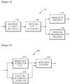
- FIG. 1 is a block diagram of an image encoding apparatus 100 for encoding an image.
- the image encoding apparatus 100 may be implemented as a hardware apparatus such as, for example, a processor of a computer or a computer system.
- the image encoding apparatus 100 may be also implemented as a software module residing on the computer system.
- the image encoding apparatus 100 includes a maximum encoding unit divider 110, an encoding depth determiner 120, an image data encoder 130, and an encoding information encoder 140 which may be implemented, for example, as hardware or software modules integrated within the image encoding apparatus 100 or separately from the image encoding apparatus 100.
- the maximum encoding unit divider 110 may divide a current frame or slice based on a maximum coding unit that is a coding unit of the largest size. That is, the maximum encoding unit divider 110 may divide the current frame or slice into at least one maximum coding unit.
- a coding unit may be represented using a maximum coding unit and a depth.
- the maximum coding unit indicates a coding unit having the largest size from among coding units of the current frame, and the depth indicates a degree of hierarchically decreasing the coding unit.
- a coding unit may decrease from a maximum coding unit to a minimum coding unit, wherein a depth of the maximum coding unit is defined as a minimum depth and a depth of the minimum coding unit is defined as a maximum depth.
- a sub coding unit of a kth depth may include a plurality of sub coding units of a (k+n)th depth (k and n are integers equal to or greater than 1).
- encoding an image in a greater coding unit may cause a higher image compression ratio.
- an image may not be efficiently encoded by reflecting continuously changing image characteristics.
- a smooth area such as the sea or sky
- the greater a coding unit is the more a compression ratio may increase.
- the smaller a coding unit is the more a compression ratio may increase.
- a different maximum image coding unit and a different maximum depth are set for each frame or slice. Since a maximum depth denotes the maximum number of times by which a coding unit may decrease, the size of each minimum coding unit included in a maximum image coding unit may be variably set according to a maximum depth. The maximum depth may be determined differently for each frame or slice or for each maximum coding unit.
- the encoding depth determiner 120 determines a division shape of the maximum coding unit.
- the division shape may be determined based on calculation of rate-distortion (RD) costs.
- the determined division shape of the maximum coding unit is provided to the encoding information encoder 140, and image data according to maximum coding units is provided to the image data encoder 130.
- a maximum coding unit may be divided into sub coding units having different sizes according to different depths, and the sub coding units having different sizes, which are included in the maximum coding unit, may be predicted or frequency-transformed based on processing units having different sizes.
- the image encoding apparatus 100 may perform a plurality of processing operations for image encoding based on processing units having various sizes and various shapes. To encode image data, processing operations such as prediction, transformation, and entropy encoding are performed, wherein processing units having the same size or different sizes may be used for every operation.
- the image encoding apparatus 100 may select a processing unit that is different from a coding unit to predict the coding unit.
- processing units for prediction may be 2N ⁇ 2N, 2N ⁇ N, N ⁇ 2N, and N ⁇ N.
- motion prediction may be performed based on a processing unit having a shape, whereby at least one of a height and a width of a coding unit is equally divided by two.
- a processing unit which is the base of prediction, is defined as a prediction unit.
- a prediction mode may be at least one of an intra mode, an inter mode, and a skip mode, and a specific prediction mode may be performed for only a prediction unit having a specific size or a specific shape.
- the intra mode may be performed for only prediction units having the sizes of 2N ⁇ 2N or N ⁇ N and the shape of a square.
- the skip mode may be performed for only a prediction unit having the size of 2N ⁇ 2N. If a plurality of prediction units exist in a coding unit, the prediction mode with the fewest encoding errors may be selected after performing prediction for every prediction unit.
- the image encoding apparatus 100 may perform frequency transform on image data based on a processing unit having a size different from a size of the coding unit.
- the frequency transform may be performed based on a processing unit having a size equal to or smaller than that of the coding unit.
- a processing unit which is the base of frequency transform, is defined as a transform unit.
- the frequency transform may be discrete cosine transform (DCT) or Karhunen Loeve transform (KLT).
- the encoding depth determiner 120 may determine sub coding units included in a maximum coding unit using RD optimization based on a Lagrangian multiplier. In other words, the encoding depth determiner 120 may determine a shape of a plurality of sub coding units divided from the maximum coding unit, wherein the sub coding units have different sizes according to the depths of sub coding units.
- the image data encoder 130 outputs a bitstream by encoding the maximum coding unit based on the division shapes determined by the encoding depth determiner 120.
- the encoding information encoder 140 encodes information about an encoding mode of the maximum coding unit determined by the encoding depth determiner 120. In other words, the encoding information encoder 140 outputs a bitstream by encoding information about a division shape of the maximum coding unit, information about the maximum depth, and information about an encoding mode of a sub coding unit for each depth.
- the information about the encoding mode of the sub coding unit may include information about a prediction unit of the sub coding unit, information about a prediction mode for each prediction unit, and information about a transform unit of the sub coding unit.
- the information about the division shape of the maximum coding unit may be flag information, indicating whether each coding unit is divided. For example, when the maximum coding unit is divided and encoded, information indicating whether the maximum coding unit is divided is encoded. Also, when a sub coding unit divided from the maximum coding unit is divided and encoded, information indicating whether the sub coding unit is divided is encoded.
- information about an encoding mode may be determined for one maximum coding unit.
- the image encoding apparatus 100 may generate sub coding units by equally dividing the height and width of a maximum coding unit by two according to an increase of depth. That is, when the size of a coding unit of a kth depth is 2N ⁇ 2N, the size of a coding unit of a (k+1)th depth is N ⁇ N.
- the image encoding apparatus 100 may determine an optimal division shape for each maximum coding unit based on sizes of maximum coding units and a maximum depth in consideration of image characteristics. By variably adjusting the size of a maximum coding unit in consideration of image characteristics and encoding an image through division of a maximum coding unit into sub coding units of different depths, images having various resolutions may be more efficiently encoded.
- FIG. 2 is a block diagram of an image decoding apparatus 200 for decoding an image according to an exemplary embodiment.
- the image decoding apparatus 200 may be implemented as a hardware apparatus such as, for example, a processor of a computer, or a computer system.
- the image decoding apparatus 200 may be also implemented as a software module residing on the computer system.
- the image decoding apparatus 200 includes an image data acquisition unit 210, an encoding information extractor 220, and an image data decoder 230 which may be implemented, for example, as hardware or software modules integrated within the image decoding apparatus 200 or separately from the image encoding apparatus 200.
- the image data acquisition unit 210 acquires image data according to maximum coding units by parsing a bitstream received by the image decoding apparatus 200 and outputs the image data to the image data decoder 230.
- the image data acquisition unit 210 may extract information about a maximum coding unit of a current frame or slice from a header of the current frame or slice. In other words, the image data acquisition unit 210 divides the bitstream in the maximum coding unit so that the image data decoder 230 may decode the image data according to maximum coding units.
- the encoding information extractor 220 extracts information about a maximum coding unit, a maximum depth, a division shape of the maximum coding unit, an encoding mode of sub coding units from the header of the current frame by parsing the bitstream received by the image decoding apparatus 200.
- the information about a division shape and the information about an encoding mode are provided to the image data decoder 230.
- the information about a division shape of the maximum coding unit may include information about sub coding units having different sizes according to depths and included in the maximum coding unit, and may be flag information indicating whether each coding unit is divided.
- the information about an encoding mode may include information about a prediction unit according to sub coding units, information about a prediction mode, and information about a transform unit.
- the image data decoder 230 restores the current frame by decoding image data of every maximum coding unit based on the information extracted by the encoding information extractor 220.
- the image data decoder 230 may decode sub coding units included in a maximum coding unit based on the information about a division shape of the maximum coding unit.
- a decoding process may include a prediction process including intra prediction and motion compensation and an inverse transform process.
- the image data decoder 230 may perform intra prediction or inter prediction based on information about a prediction unit and information about a prediction mode to predict a prediction unit.
- the image data decoder 230 may also perform inverse transform for each sub coding unit based on information about a transform unit of a sub coding unit.
- FIG. 3 illustrates hierarchical coding units.
- the hierarchical coding units may include coding units whose widths and heights are 64 ⁇ 64, 32 ⁇ 32, 16 ⁇ 16, 8 ⁇ 8, and 4 ⁇ 4. Besides these coding units having perfect square shapes, coding units whose widths and heights are 64 ⁇ 32, 32 ⁇ 64, 32 ⁇ 16, 16 ⁇ 32, 16 ⁇ 8, 8 ⁇ 16, 8 ⁇ 4, and 4 ⁇ 8 may also exist.
- the size of a maximum coding unit is set to 64 ⁇ 64, and a maximum depth is set to 2.
- the size of a maximum coding unit is set to 64 ⁇ 64, and a maximum depth is set to 3.
- the size of a maximum coding unit is set to 16 ⁇ 6, and a maximum depth is set to 1.
- a maximum size of a coding unit may be set relatively great to increase a compression ratio and reflect image characteristics more precisely. Accordingly, for the image data sets 310 and 320 having higher resolution than the image data set 330, 64 ⁇ 64 may be selected as the size of a maximum coding unit.
- a maximum depth indicates the total number of layers in the hierarchical coding units. Since the maximum depth of the image data set 310 is 2, a coding unit 315 of the image data set 310 may include a maximum coding unit whose longer axis size is 64 and sub coding units whose longer axis sizes are 32 and 16, according to an increase of a depth.
- a coding unit 335 of the image data set 330 may include a maximum coding unit whose longer axis size is 16 and coding units whose longer axis sizes is 8, according to an increase of a depth.
- a coding unit 325 of the image data set 320 may include a maximum coding unit whose longer axis size is 64 and sub coding units whose longer axis sizes are 32, 16, 8 and 4 according to an increase of a depth. Since an image is encoded based on a smaller sub coding unit as a depth increases, examples are suitable for encoding an image including more minute scenes.
- FIG. 4 is a block diagram of an image encoder 400 based on a coding unit.
- the image encoder 400 may be implemented as a hardware device such as, for example, a processor of a computer or as a software module residing on the computer system.
- An intra predictor 410 performs intra prediction on prediction units of the intra mode in a current frame 405, and a motion estimator 420 and a motion compensator 425 perform inter prediction and motion compensation on prediction units of the inter mode using the current frame 405 and a reference frame 495.
- the intra predictor 410, the motion estimator 420, the motion compensator 425, and the reference frame 495 may be implemented, for example, as hardware or software modules integrated within the image encoder 400 or separately from the image encoder 400.
- Residual values are generated based on the prediction units output from the intra predictor 410, the motion estimator 420, and the motion compensator 425.
- the generated residual values are output as quantized transform coefficients by passing through a transformer 430 and a quantizer 440.
- the quantized transform coefficients are restored to residual values by passing through an inverse quantizer 460 and an inverse transformer 470, and the restored residual values are post-processed by passing through a deblocking unit 480 and a loop filtering unit 490 and output as the reference frame 495.
- the quantized transform coefficients may be output as a bitstream 455 by passing through an entropy encoder 450.
- the intra predictor 410, the motion estimator 420, the motion compensator 425, the transformer 430, the quantizer 440, the entropy encoder 450, the inverse quantizer 460, the inverse transformer 470, the deblocking unit 480, and the loop filtering unit 490 of the image encoder 400 perform image encoding processes based on a maximum coding unit, a sub coding unit according to depths, a prediction unit, and a transform unit.
- FIG. 5 is a block diagram of an image decoder 500 based on a coding unit, according to an exemplary embodiment.
- the image decoder 500 may be implemented as a hardware device such as, for example, a processor of a computer or as a software module residing on the computer system.
- a bitstream 505 passes through a parser 510 so that the encoded image data to be decoded and encoding information necessary for decoding are parsed.
- the encoded image data is output as inverse-quantized data by passing through an entropy decoder 520 and an inverse quantizer 530 and restored to residual values by passing through an inverse transformer 540.
- the residual values are restored according to coding units by being added to an intra prediction result of an intra predictor 550 or a motion compensation result of a motion compensator 560.
- the restored coding units 585, 595 are used for prediction of next coding units or a next frame by passing through a deblocking unit 570 and a loop filtering unit 580.
- the parser 510, the entropy decoder 520, the inverse quantizer 530, the inverse transformer 540, the intra predictor 550, the compensator 560, the deblocking unit 570, and the loop filtering unit 580 may be implemented, for example, as hardware or software modules integrated within the image decoder 500 or separately from the image decoder 500.
- the parser 510, the entropy decoder 520, the inverse quantizer 530, the inverse transformer 540, the intra predictor 550, the motion compensator 560, the deblocking unit 570, and the loop filtering unit 580 of the image decoder 500 perform image decoding processes based on a maximum coding unit, a sub coding unit according to depths, a prediction unit, and a transform unit.
- the intra predictor 550 and the motion compensator 560 determine a prediction unit and a prediction mode in a sub coding unit by considering a maximum coding unit and a depth, and the inverse transformer 540 performs inverse transform by considering the size of a transform unit.
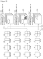
- FIG. 6 illustrates a maximum coding unit, a sub coding unit, and a prediction unit.
- the image encoding apparatus 100 illustrated in FIG. 1 and the image decoding apparatus 200 illustrated in FIG. 2 use hierarchical coding units to perform encoding and decoding in consideration of image characteristics.
- a maximum coding unit and a maximum depth may be adaptively set according to the image characteristics or variously set according to requirements of a user.
- a hierarchical coding unit structure 600 has a maximum encoding unit 610 which is a maximum coding unit whose height and width are 64 and maximum depth is 4.
- a depth increases along a vertical axis of the hierarchical coding unit structure 600, and as a depth increases, heights and widths of sub coding units 620 to 650 decrease.
- Prediction units of the maximum encoding unit 610 and the sub coding units 620 to 650 are shown along a horizontal axis of the hierarchical coding unit structure 600.
- the maximum encoding unit 610 has a depth of 0 and the size of an coding unit, or a height and a width, of 64 ⁇ 64.
- a depth increases along the vertical axis, and there exist a first sub coding unit 620 whose size is 32 ⁇ 32 and depth is 1, a second sub coding unit 630 whose size is 16 ⁇ 16 and depth is 2, a third sub coding unit 640 whose size is 8 ⁇ 8 and depth is 3, and a minimum encoding unit 650 whose size is 4 ⁇ 4 and depth is 4.
- the minimum encoding unit 650 whose size is 4 ⁇ 4 and depth is 4 is a minimum coding unit, and the minimum coding unit may be divided into prediction units, each of which is a size smaller than the minimum coding unit.
- a prediction unit of the maximum encoding unit 610 whose depth is 0 may be a prediction unit whose size is equal to the size 64x64 of the maximum coding unit, or a prediction unit 612 whose size is 64 ⁇ 32, a prediction unit 614 whose size is 32 ⁇ 64, or a prediction unit 616 whose size is 32 ⁇ 32, which has a size smaller than that of the maximum coding unit whose size is 64 ⁇ 64.
- a prediction unit of the first sub coding unit 620 whose depth is 1 and size is 32 ⁇ 32 may be a prediction unit whose size is equal to the size 32x32 of the first sub coding unit, or a prediction unit 622 whose size is 32 ⁇ 16, a prediction unit 624 whose size is 16 ⁇ 32, or a prediction unit 626 whose size is 16 ⁇ 16, which has a size smaller than that of the first sub coding unit 620 whose size is 32 ⁇ 32.
- a prediction unit of the second sub coding unit 630 whose depth is 2 and size is 16 ⁇ 16 may be a prediction unit whose size is equal to the size 16x16 of the second sub coding unit 630, or a prediction unit 632 whose size is 16 ⁇ 8, a prediction unit 634 whose size is 8 ⁇ 16, or a prediction unit 636 whose size is 8 ⁇ 8, which has a size smaller than that of the second sub coding unit 630 whose size is 16 ⁇ 16.
- a prediction unit of the third sub coding unit 640 whose depth is 3 and size is 8 ⁇ 8 may be a prediction unit whose size is equal to the size 8x8 of the third sub coding unit 640 or a prediction unit 642 whose size is 8 ⁇ 4, a prediction unit 644 whose size is 4 ⁇ 8, or a prediction unit 646 whose size is 4 ⁇ 4, which has a size smaller than that of the third sub coding unit 640 whose size is 8 ⁇ 8.
- the minimum encoding unit 650 whose depth is 4 and size is 4 ⁇ 4 is a minimum coding unit and a coding unit of a maximum depth.
- a prediction unit of the minimum encoding unit 650 may be a prediction unit 650 whose size is 4 ⁇ 4, a prediction unit 652 having a size of 4 ⁇ 2, a prediction unit 654 having a size of 2 ⁇ 4, or a prediction unit 656 having a size of 2 ⁇ 2.
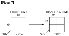
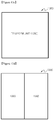
- FIG. 7 illustrates a coding unit and a transform unit.
- the image encoding apparatus 100 illustrated in FIG. 1 and the image decoding apparatus 200 illustrated in FIG. 2 perform encoding and decoding with a maximum coding unit or with sub coding units, which have size equal to or smaller than the maximum coding unit, divided from the maximum coding unit.
- the size of a transform unit for frequency transform is selected to be no larger than that of a corresponding coding unit. For example, if a current coding unit 710 has the size of 64 ⁇ 64, frequency transform may be performed using a transform unit 720 having the size of 32 ⁇ 32.
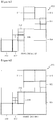
- FIGS. 8A, 8B , 8C, and 8D illustrate division shapes of a coding unit, a prediction unit, and a transform unit.
- FIGS. 8A and 8B respectively illustrate a coding unit and a prediction unit.
- FIG. 8A shows a division shape selected by the image encoding apparatus 100 illustrated in FIG. 1 , to encode a maximum coding unit 810.
- the image encoding apparatus 100 divides the maximum coding unit 810 into various shapes, performs encoding, and selects an optimal division shape by comparing encoding results of various division shapes with each other based on the RD costs.
- the maximum coding unit 810 may be encoded without dividing the maximum coding unit 810, as illustrated in FIGS. 8A through 8D .
- the maximum coding unit 810 whose depth is 0 is encoded by dividing the maximum encoding unit 810 into sub coding units 812, 854 whose depths are equal to or greater than 1. That is, the maximum coding unit 810 is divided into 4 sub coding units whose depths are 1, and all or some of the sub coding units whose depths are 1 are divided into sub coding units 814, 816, 818, 828, 850, and 852 whose depths are 2.
- a sub coding unit located in an upper-right side and a sub coding unit located in a lower-left side among the sub coding units whose depths are 1 are divided into sub coding units whose depths are equal to or greater than 2.
- Some of the sub coding units whose depths are equal to or greater than 2 may be further divided into sub coding units 820, 822, 824, 826, 830, 832, 840, 842, 844, 846, and 848 whose depths are equal to or greater than 3.
- FIG. 8B shows a division shape of a prediction unit for the maximum coding unit 810.
- a prediction unit 860 for the maximum coding unit 810 may be divided differently from the maximum coding unit 810. In other words, a prediction unit for each of sub coding units may be smaller than a corresponding sub coding unit.
- a prediction unit for a sub coding unit 854 located in a lower-right side among the sub coding units 812, 854 whose depths are 1 may be smaller than the sub coding unit 854.
- prediction units for sub coding units 814, 816, 850, and 852 of sub coding units 814, 816, 818, 828, 850, and 852 whose depths are 2 may be smaller than the sub coding units 814, 816, 850, and 852, respectively.
- prediction units for sub coding units 822, 832, and 848 whose depths are 3 may be smaller than the sub coding units 822, 832, and 848, respectively.
- the prediction units may have a shape whereby respective sub coding units are equally divided by two in a direction of height or width or have a shape whereby respective sub coding units are equally divided by four in directions of height and width.
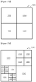
- FIGS. 8C and 8D illustrate a prediction unit and a transform unit.
- FIG. 8C shows a division shape of a prediction unit for the maximum coding unit 810 shown in FIG. 8B
- FIG. 8D shows a division shape of a transform unit of the maximum coding unit 810.
- a division shape of a transform unit 870 may be set differently from the prediction unit 860.
- a transform unit may be selected with the original size of the sub coding unit 854.
- prediction units for sub coding units 814 and 850 whose depths are 2 are selected with a shape whereby the height of each of the sub coding units 814 and 850 is equally divided by two
- a transform unit may be selected with the same size as the original size of each of the sub coding units 814 and 850.
- a transform unit may be selected with a smaller size than a prediction unit. For example, when a prediction unit for the sub coding unit 852 whose depth is 2 is selected with a shape whereby the width of the sub coding unit 852 is equally divided by two, a transform unit may be selected with a shape whereby the sub coding unit 852 is equally divided by four in directions of height and width, which has a smaller size than the shape of the prediction unit.
- a transform unit may be set to have a larger size than a coding unit, regardless of the coding unit.
- FIG. 9 is a block diagram of an apparatus 900 for encoding an image.
- the image encoding apparatus 900 includes a predictor 910, a transformer 920, a quantizer 930, and an entropy encoder 940.
- the predictor 910 generates residual values by performing intra prediction or inter prediction on one or more coding units.
- residual values included in a plurality of prediction units may be grouped into one transform unit and then transformed to a frequency domain, and thus the residual values are generated by predicting the one or more coding units based on the plurality of prediction units.
- the transform to the frequency domain may be DCT or KLT.
- one coding unit may include a plurality of prediction units.
- the predictor 910 may predict each of the prediction units, and generate the residual values of the prediction units included in the one coding unit.
- the prediction unit 910 may predict the plurality of coding units all at once.
- a plurality of prediction units included in a plurality of coding units may be grouped into one transform unit, and thus residual values are generated by predicting each of the prediction units included in the coding units.
- all sub coding units included in one maximum coding unit may be predicted in order to generate the residual values of the coding units.
- transform e.g. DCT or KLT
- a predetermined prediction unit is independently encoded, restored, and then used to predict a next prediction unit.
- a method of encoding an image which will be described later, since transform is performed by grouping prediction units included in one or more coding units into one transform unit, a predetermined prediction unit cannot be independently encoded and restored. This will be described in detail with reference to FIG. 10 .
- FIG. 10 is a diagram for describing a prediction method.
- one coding unit 1000 may include a plurality of prediction units 1010 through 1040. If transform is performed with a size smaller than or equal to a prediction unit, as in conventional technology, the prediction units 1010 through 1030 may be encoded and restored before encoding the prediction unit 1040 at a lower-right side.
- the prediction unit 1040 is intra predicted by using pixels adjacent to the prediction unit 1040, from among pixels generated by encoding and then restoring the prediction units 1010 through 1030.
- a plurality of prediction units are grouped into one transform unit, and then transform is performed.
- the prediction unit 1040 at the lower-right side is encoded with the other prediction units 1010 through 1030, and thus the prediction units 1010 through 1030 are not encoded before encoding the prediction unit 1040. Accordingly, the prediction unit 1040 cannot be intra predicted by using the pixels generated by encoding and then restoring the prediction units 1010 through 1030.
- the prediction unit 910 of FIG. 9 may predict the prediction unit 1040 by using prediction values of the prediction units 1010 through 1030.
- the prediction unit 1040 at the lower-right side is predicted by using the prediction values of the prediction units 1010 through 1030, instead of the pixels generated by encoding and then restoring the prediction units 1010 through 1030.
- the first prediction unit may be intra predicted by using prediction values of at least one adjacent prediction unit.
- the prediction units grouped into one transform unit may all be predicted via inter prediction.
- all prediction units grouped into the transform unit may be predicted by using only inter prediction.
- the transformer 920 receives an image processing unit in a pixel domain, and transforms the image processing unit into a frequency domain.
- the transformer 920 transforms the residual values generated by the prediction unit 910 into the frequency domain.
- the transformer 920 groups the prediction units into one transform unit, and performs DCT or KLT according to the transform unit.
- the residual values may be residual values of a plurality of prediction units included in one or more coding units. Coefficients of frequency components are generated as a result of transforming the pixel domain to the frequency domain.
- the transform to the frequency domain may be performed via DCT or KLT, and discrete cosine coefficients are generated as a result of the DCT or KLT.
- any transform for transforming an image in a pixel domain to the frequency domain may be used.
- FIG. 11 is a block diagram of the transformer 920.
- the transformer 920 includes a selector 1110 and a transform performer 1120.
- the selector 1110 sets one transform unit by selecting a plurality of adjacent prediction units.
- intra prediction or inter prediction is performed according to a predetermined prediction unit and DCT or KLT is performed with a size smaller than or equal to the predetermined prediction unit.
- the conventional image encoding apparatuses perform DCT or KLT based on a transform unit having a size smaller than or equal to a prediction unit.
- the image encoding apparatus 900 groups the adjacent prediction units into one transform unit, and then performs DCT or KLT according to the transform unit. Specifically, since it is highly likely that the adjacent prediction units have similar residual values, a compression ratio of encoding may be remarkably increased when DCT or KLT is performed according to the transform unit generated by grouping the adjacent prediction units.
- the selector 1110 selects the prediction units to be grouped into one transform unit and on which DCT or KLT is to be performed.
- the prediction units may be adjacent to each other. This will be described in detail with reference to FIGS. 12A through 12C and 13A through 13D .
- FIGS. 12A through 12C are diagrams of types of transform units 1230 through 1250.
- a prediction unit 1220 may have a shape whereby a coding unit 1210 is equally divided by two in a direction of width.
- the coding unit 1210 may be a maximum coding unit as described above, or a sub coding unit having a smaller size than the maximum coding unit.
- the transform units 1230 through 1250 may be different.
- a size of the transform unit 1230 may be smaller than that of the prediction unit 1220 as shown in FIG. 12A , or a size of the transform unit 1240 may be identical to that of the prediction unit 1220 as shown in FIG. 12B .
- a size of the transform unit 1250 may be larger than that of the prediction unit 1220 as shown in FIG. 12C .
- the prediction units grouped into one transform unit may be a plurality of prediction units included in one coding unit as shown in FIGS. 12A through 12C , or may be a plurality of prediction units included in different coding units. In other words, a plurality of prediction units included in at least one coding unit may be grouped into one transform unit and then transformed to the frequency domain.
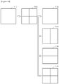
- FIGS. 13A through 13D are diagrams of types of transform units.
- One maximum coding unit 1300 may be divided into sub coding units 1302 through 1308 having different sizes and then encoded as shown in FIG. 13A , and each of the sub coding units 1302 through 1308 may include at least one prediction unit 1310 through 1340, as shown in FIG. 13B .
- the selector 1110 may group the prediction units 1310 through 1340 shown in FIG. 13B into one transform unit 1350 shown in FIG. 13C , and then transform the transform unit 1350 into the frequency domain.
- the selector 1110 may group the prediction units 1310 and 1330 through 1339 of the sub coding units 1302 and 1306 on the left into one transform unit 1360, and group the prediction units 1320 through 1328 and 1340 of the sub coding units 1304 and 1308 on the right into one transform unit 1362, as shown in FIG. 13D .
- a criterion for the selector 1110 to select a plurality of adjacent prediction units is not limited.
- the selector 1110 may select a transform unit based on a depth.
- the depth indicates a degree of hierarchically decreasing a coding unit from a maximum coding unit of a current slice or frame to sub coding units.
- a size of a sub coding unit decreases, and thus a size of a prediction unit included in the sub coding unit decreases.
- DCT or KLT is performed according to a transform unit having a size smaller than or equal to a prediction unit, a compression ratio of image encoding is decreased because header information is added for each transform unit as described above.
- prediction units included in a sub coding unit whose depth is equal to or above a predetermined value may be grouped into one transform unit, and then DCT or KLT may be performed on the transform unit.
- the selector 1110 may set the transform unit based on the depth of the sub coding unit. For example, when a depth of the coding unit 1210 of FIG. 12C is higher than k, the selector 1110 groups the prediction units 1220 into one transform unit 1250.
- the selector 1110 may group prediction units of the sub coding units into one transform unit.
- FIG. 13C illustrates an example of grouping prediction units of sub coding units whose depth is larger than a maximum coding unit, i.e., whose depth is larger than 1, into one transform unit.
- the selector 1110 may set a plurality of adjacent prediction units, on which prediction is performed according to a same type of prediction mode, into one transform unit.
- the adjacent prediction units that are predicted by using intra prediction or inter prediction are grouped into one transform unit. Since it is highly likely that the adjacent prediction units that are predicted according to the same type of prediction mode have similar residual values, DCT or KLT may be performed by grouping the adjacent prediction units into one transform unit.
- the transform performer 1120 transforms the adjacent prediction units into a frequency domain according to the set transform unit.
- Coefficients of frequency domain e.g. discrete cosine coefficients
- the quantizer 930 quantizes the frequency component coefficients generated by the transformer 920.
- the quantizer 930 may quantize the coefficients input according to a predetermined quantization process.
- the entropy encoder 940 entropy-encodes the coefficients quantized by the quantizer 930.
- the discrete cosine coefficients may be entropy-encoded by using context-adaptive binary arithmetic coding (CABAC) or context-adaptive variable length coding (CAVLC).
- CABAC context-adaptive binary arithmetic coding
- CAVLC context-adaptive variable length coding
- the image encoding apparatus 900 may encode flag information indicating whether the transform unit generated by grouping the prediction units includes the coefficients. If there are no coefficients to be entropy-encoded, i.e., when the quantized coefficients are all '0', flag information indicating that the transform unit does not include the coefficients is encoded, and the quantized coefficients are not separately entropy-encoded.
- the image encoding apparatus 900 may determine an optimum transform unit by repeatedly performing transform, quantization, and entropy encoding on different transform units.
- the optimum transform unit may be determined by mechanically repeating a process of selecting a plurality of prediction units by using various methods, instead of selecting the prediction units based on a predetermined criterion, such as a depth or a same type of prediction mode.
- the optimum transform unit may be determined based on calculation of RD costs, and this will be described in detail with reference to FIG. 14 .
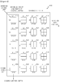
- FIG. 14 is a diagram of different example transform units 1430 through 1460.
- the image encoding apparatus 900 repeatedly encodes different transform units 1430 through 1460.
- a coding unit 1410 may be predicted and encoded based on a prediction unit 1420 having a size smaller than the coding unit 1410.
- DCT or KLT is performed on residual values generated as a result of prediction, and here, the DCT or KLT may be performed based on the different transform units 1430 through 1460 as shown in FIG. 14 .
- the transform unit 1430 has the same size as the coding unit 1410, and is generated by grouping all prediction units included in the coding unit 1410.
- the transform units 1440 have a size whereby the coding unit 1410 is equally divided by two in a direction of width, and are generated by grouping the prediction units that are adjacent in a vertical direction.
- the transform units 1450 have a size whereby the coding unit 1410 is equally divided by two in a direction of height, and are generated by grouping the prediction units that are adjacent in a horizontal direction.
- the transform units 1460 have the same sizes as the prediction units 1420.
- the image encoding apparatus 900 may determine the optimum transform unit by repeatedly performing transform, quantization, and entropy encoding on the transform units 1430 through 1460.
- the image encoding apparatus 900 may encode flag information indicating whether the transform unit is generated by grouping a plurality of prediction units included in one or more coding units. For example, when a transform unit is set by grouping a plurality of prediction units included in one coding unit as shown in FIGS. 12A through 12C , flag information is set to '0', and when a transform unit is set by grouping a plurality of prediction units included in a plurality of coding units as shown in FIGS. 13A through 13D , flag information is set to '1'.
- FIG. 14 illustrates an example of determining the optimum transform unit when one transform unit is set by grouping prediction units included in one coding unit.
- the optimum transform unit may be determined by repeatedly performing DCT, quantization, and entropy encoding on different transform units, as shown in FIG. 14 , even when one transform unit is set by grouping prediction units included in a plurality of coding units.
- FIG. 15 is a block diagram of an apparatus 1500 for decoding an image, according to another exemplary embodiment.
- the image decoding apparatus 1500 includes an entropy decoder 1510, an inverse quantizer 1520, an inverse transformer 1530, and a restorer 1540.
- the entropy decoder 1510 entropy-decodes frequency component coefficients of a predetermined transform unit.
- the transform unit may be generated by grouping a plurality of prediction units.
- the prediction units may be adjacent to each other, and may be included in one coding unit or in a plurality of different coding units.
- the transform unit may be generated by grouping a plurality of adjacent prediction units based on a depth, or by grouping a plurality of adjacent prediction units on which prediction is performed according to a same type of prediction mode, i.e., according to an intra prediction mode or an inter prediction mode.
- an optimum transform unit may be selected by repeatedly performing transform, quantization, and entropy decoding on different transform units by mechanically repeating a process of grouping a plurality of prediction units.
- the entropy decoder 1510 may not separately entropy-decode quantized coefficients. If the transform unit does not include the quantized coefficients, the quantized coefficients are not separately entropy-encoded by referring to predetermined flag information.
- the inverse quantizer 1520 inverse-quantizes the frequency component coefficients that are entropy-decoded by the entropy decoder 1510.
- the frequency component coefficients that are entropy-decoded according to a quantization step used while encoding the transform unit are inverse-quantized.
- the inverse transformer 1530 inverse-transforms the inverse-quantized frequency component coefficients into a pixel domain. Inverse DCT or inverse KLT is performed on the inverse-quantized discrete cosine coefficients to restore a transform unit in a pixel domain. As a result of inverse transform, residual values of the transform unit are restored.
- the restored transform unit includes a plurality of prediction units, and as described above, the prediction units may be included in one coding unit or in a plurality of different coding units.
- the restorer 1540 generates prediction values by predicting a plurality of prediction units included in the restored transform unit. Prediction values of one coding unit are generated if the prediction units grouped into one transform unit are included in one coding unit, and prediction values of a plurality of coding units are generated if the prediction units grouped into one transform unit are included in a plurality of coding units. One coding unit or a plurality of coding units is restored by adding the generated prediction values and the residual values restored by the inverse transformer 1530.
- Whether the prediction values are generated for one coding unit or a plurality of coding units may be determined based on flag information indicating whether the image encoding apparatus 900 generated a transform unit by grouping a plurality of prediction units included in one coding unit or in a plurality of coding units.
- intra prediction may be performed based on prediction values of at least one adjacent prediction unit, as described with reference to FIG. 10 .
- a plurality of prediction units grouped into one transform unit may all be predicted by using inter prediction.
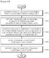
- FIG. 16 is a flowchart illustrating a method of encoding an image.
- an apparatus for encoding an image generates residual values by performing prediction on one or more coding units in operation 1610.
- a plurality of prediction units grouped into one transform unit may be included in one coding unit or in a plurality of coding units. Accordingly, when the prediction units are included in one coding unit, the residual values are generated by performing prediction on one coding unit, and when the prediction units are included in a plurality of coding units, the residual values are generated by performing prediction on the plurality of coding units.
- the apparatus sets one transform unit by selecting a plurality of prediction units.
- the prediction units may be included in one coding unit or in a plurality of coding units.
- the adjacent prediction units may be selected based on depth, or adjacent prediction units on which prediction is performed in a same type of prediction mode may be selected.
- the apparatus transforms the prediction units into a frequency domain according to the transform unit set in operation 1620.
- Coefficients of frequency domain are generated by performing transform on the transform unit set by grouping the prediction units.
- the apparatus quantizes frequency component coefficients, e.g. the discrete cosine coefficients generated in operation 1630, according to a predetermined quantization process.
- the apparatus entropy-encodes the frequency component coefficients quantized in operation 1640.
- the entropy encoding is performed via CABAC or CAVLC.
- the method may further include setting an optimum transform unit by repeating operations 1610 through 1640 on different transform units.
- the optimum transform unit may be set by repeatedly performing transform, quantization, and entropy encoding on the different transform units as shown in FIG. 14 .
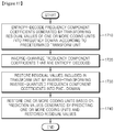
- FIG. 17 is a flowchart illustrating a method of decoding an image.
- the apparatus entropy-decodes frequency component coefficients of a predetermined transform unit, in operation 1710.
- the frequency component coefficients may be discrete cosine coefficients.
- the transform unit may be set by grouping a plurality of prediction units. As described above, the prediction units may be adjacent to each other, and may be included in one coding unit or in a plurality of different coding units.
- the apparatus inverse-quantizes the frequency component coefficients that are entropy-decoded in operation 1710.
- the discrete cosine coefficients are inverse-quantized by using a quantization step used during encoding.
- the apparatus inverse-transforms the frequency component coefficients that are inverse-quantized in operation 1720 into a pixel domain to restore a transform unit.
- the restored transform unit is set by grouping a plurality of prediction units. Residual values included in the transform unit are restored. Residual values of one coding unit are restored if the prediction units are included in one coding unit, and residual values of a plurality of coding units are restored if the prediction units are included in the coding units.
- the transform unit may be set by grouping adjacent prediction units based on a depth, or by grouping adjacent prediction units on which prediction is performed according to a same type of prediction mode.
- the apparatus restores the one or more coding units based on the residual values included in the transform unit restored in operation 1730.
- Prediction values are generated by predicting the one or more coding units, and the one or more coding units are restored by adding the generated prediction values and the residual values restored in operation 1730.
- a method of predicting the prediction values included in one or more coding units has been described above with reference to FIG. 10 . If the transform unit is set by grouping the prediction units included in one coding unit, one coding unit is restored, and if the transform unit is set by grouping the prediction units included in a plurality of coding units, the plurality of coding units are restored.
- an image is more efficiently compressed and encoded since a transform unit can be set to have a size larger than a prediction unit, and transform can be performed on the transform unit.
- the image encoding or decoding apparatus or the image encoder or decoder illustrated in FIG. 1, 2 , 4 , 5 , 9 , 11 , or 15 may include a bus coupled to every unit of the apparatus or encoder or decoder, at least one processor that is connected to the bus and is for executing commands, and memory connected to the bus to store the commands, received messages, and generated messages.
Landscapes
- Engineering & Computer Science (AREA)
- Multimedia (AREA)
- Signal Processing (AREA)
- Physics & Mathematics (AREA)
- General Physics & Mathematics (AREA)
- Discrete Mathematics (AREA)
- Theoretical Computer Science (AREA)
- Compression Or Coding Systems Of Tv Signals (AREA)
- Compression, Expansion, Code Conversion, And Decoders (AREA)
- Compression Of Band Width Or Redundancy In Fax (AREA)
- Image Processing (AREA)
Claims (1)
- Appareil pour décoder une image, l'appareil comprenant :un processeur qui est configuré pour déterminer une pluralité d'unités de codage maximal de carré à partir d'une image et déterminer une unité de codage de carré qui est séparée de façon hiérarchique d'une unité de codage maximal parmi la pluralité d'unités de codage maximal à l'aide d'informations concernant une unité de codage, dans lequel les informations concernant une unité de codage sont analysées à partir du train de bits ; etun décodeur qui est configuré pour reconstruire des résidus en réalisant une quantification inverse et une transformation inverse sur des coefficients de transformation quantifiés d'une unité de transformation analysée à partir du train de bits,réaliser une prédiction intra ou une prédiction inter à l'aide d'au moins une unité de prédiction incluse dans l'unité de codage pour générer un prédicteur etreconstruire l'unité de codage à l'aide des résidus et du prédicteur,dans lequel le processeur est configuré pour déterminer la ou les unités de prédiction, qui sont séparées de l'unité de codage à l'aide d'informations concernant une unité de prédiction, dans lequel les informations concernant une unité de prédiction sont analysées à partir du train de bits etdéterminer au moins une unité de transformation qui est séparée de l'unité de codage à l'aide d'informations concernant une unité de transformation, dans lequel les informations concernant une unité de transformation sont analysées à partir du train de bits,dans lequel, lorsqu'il est déterminé que le mode de prédiction est un mode de prédiction inter et non pas un mode de prédiction intra, l'appareil de décodage est configuré pour prendre en charge une unité de transformation, parmi la ou les unités de transformation, ayant une taille de 2N x 2N, qui comprend quatre unités de prédiction, parmi la ou les unités de prédiction, ayant une taille de N x N,dans lequel la ou les unités de prédiction constituent l'un des blocs comprenant : un bloc dont la taille est égale à celle de l'unité de codage ; et un bloc parmi une pluralité de blocs générés en divisant de manière égale la hauteur et/ou la largeur de l'unité de codage etdans lequel l'unité de transformation constitue l'un des blocs comprenant : un bloc dont la taille est égale à celle de l'unité de codage ; et un bloc parmi une pluralité de blocs générés en divisant de manière égale la hauteur et/ou la largeur de l'unité de codage.
Priority Applications (4)
| Application Number | Priority Date | Filing Date | Title |
|---|---|---|---|
| RS20171022A RS56435B1 (sr) | 2010-01-14 | 2011-01-14 | Metod i aparat za kodiranje i dekodiranje slike korišćenjem velike jedinice za transformaciju |
| SI201131318T SI2996337T1 (sl) | 2010-01-14 | 2011-01-14 | Postopek in naprava za kodiranje in dekodiranje podobe z uporabo velike transformacijske enote |
| PL15183038T PL2996337T3 (pl) | 2010-01-14 | 2011-01-14 | Sposób i urządzenie do kodowania i dekodowania obrazu przy wykorzystaniu dużej jednostki przekształcania |
| HRP20171542TT HRP20171542T1 (hr) | 2010-01-14 | 2017-10-12 | Postupak i ureðaj za kodiranje i dekodiranje slike korištenjem velike transformacijske jedinice |
Applications Claiming Priority (2)
| Application Number | Priority Date | Filing Date | Title |
|---|---|---|---|
| KR20100003558A KR101487687B1 (ko) | 2010-01-14 | 2010-01-14 | 큰 크기의 변환 단위를 이용한 영상 부호화, 복호화 방법 및 장치 |
| EP11733110.8A EP2524508A4 (fr) | 2010-01-14 | 2011-01-14 | Procédé et appareil pour encoder et décoder une image en utilisant une unité de transformation importante |
Related Parent Applications (1)
| Application Number | Title | Priority Date | Filing Date |
|---|---|---|---|
| EP11733110.8A Division EP2524508A4 (fr) | 2010-01-14 | 2011-01-14 | Procédé et appareil pour encoder et décoder une image en utilisant une unité de transformation importante |
Publications (2)
| Publication Number | Publication Date |
|---|---|
| EP2996337A1 EP2996337A1 (fr) | 2016-03-16 |
| EP2996337B1 true EP2996337B1 (fr) | 2017-10-11 |
Family
ID=44258572
Family Applications (7)
| Application Number | Title | Priority Date | Filing Date |
|---|---|---|---|
| EP15183038.7A Active EP2996337B1 (fr) | 2010-01-14 | 2011-01-14 | Procédé et appareil pour encoder et décoder une image en utilisant une unité de transformation importante |
| EP11733110.8A Ceased EP2524508A4 (fr) | 2010-01-14 | 2011-01-14 | Procédé et appareil pour encoder et décoder une image en utilisant une unité de transformation importante |
| EP17190156.4A Active EP3300371B1 (fr) | 2010-01-14 | 2011-01-14 | Procédé de codage et de décodage et appareil de codage d'une image à l'aide d'une unité de transformation de grande taille |
| EP15183034.6A Active EP2996340B1 (fr) | 2010-01-14 | 2011-01-14 | Procédé et appareil pour encoder et décoder une image en utilisant une unité de transformation importante |
| EP15183039.5A Active EP2996342B1 (fr) | 2010-01-14 | 2011-01-14 | Procédé et appareil pour encoder et décoder une image en utilisant une unité de transformation importante |
| EP18208919.3A Active EP3468202B1 (fr) | 2010-01-14 | 2011-01-14 | Procédé de codage d'une image au moyen d'une unité de transformation de grande taille |
| EP15183036.1A Active EP2996341B1 (fr) | 2010-01-14 | 2011-01-14 | Procédé et appareil pour encoder et décoder une image en utilisant une unité de transformation importante |
Family Applications After (6)
| Application Number | Title | Priority Date | Filing Date |
|---|---|---|---|
| EP11733110.8A Ceased EP2524508A4 (fr) | 2010-01-14 | 2011-01-14 | Procédé et appareil pour encoder et décoder une image en utilisant une unité de transformation importante |
| EP17190156.4A Active EP3300371B1 (fr) | 2010-01-14 | 2011-01-14 | Procédé de codage et de décodage et appareil de codage d'une image à l'aide d'une unité de transformation de grande taille |
| EP15183034.6A Active EP2996340B1 (fr) | 2010-01-14 | 2011-01-14 | Procédé et appareil pour encoder et décoder une image en utilisant une unité de transformation importante |
| EP15183039.5A Active EP2996342B1 (fr) | 2010-01-14 | 2011-01-14 | Procédé et appareil pour encoder et décoder une image en utilisant une unité de transformation importante |
| EP18208919.3A Active EP3468202B1 (fr) | 2010-01-14 | 2011-01-14 | Procédé de codage d'une image au moyen d'une unité de transformation de grande taille |
| EP15183036.1A Active EP2996341B1 (fr) | 2010-01-14 | 2011-01-14 | Procédé et appareil pour encoder et décoder une image en utilisant une unité de transformation importante |
Country Status (21)
| Country | Link |
|---|---|
| US (9) | US8842927B2 (fr) |
| EP (7) | EP2996337B1 (fr) |
| JP (5) | JP5718363B2 (fr) |
| KR (1) | KR101487687B1 (fr) |
| CN (6) | CN102792695B (fr) |
| BR (5) | BR122020024474B1 (fr) |
| CY (5) | CY1119910T1 (fr) |
| DK (5) | DK2996340T3 (fr) |
| ES (5) | ES2644043T3 (fr) |
| HR (5) | HRP20171542T1 (fr) |
| HU (5) | HUE044399T2 (fr) |
| LT (5) | LT2996342T (fr) |
| MY (5) | MY187111A (fr) |
| NO (1) | NO2996341T3 (fr) |
| PH (4) | PH12015500842B1 (fr) |
| PL (5) | PL2996340T3 (fr) |
| PT (5) | PT2996340T (fr) |
| RS (5) | RS56434B1 (fr) |
| SI (5) | SI2996342T1 (fr) |
| TR (1) | TR201900307T4 (fr) |
| WO (1) | WO2011087323A2 (fr) |
Families Citing this family (27)
| Publication number | Priority date | Publication date | Assignee | Title |
|---|---|---|---|---|
| KR101474756B1 (ko) | 2009-08-13 | 2014-12-19 | 삼성전자주식회사 | 큰 크기의 변환 단위를 이용한 영상 부호화, 복호화 방법 및 장치 |
| KR101712097B1 (ko) * | 2009-08-19 | 2017-03-03 | 삼성전자 주식회사 | 유연한 직교 변환에 기초한 영상 부호화, 복호화 방법 및 장치 |
| KR101487687B1 (ko) * | 2010-01-14 | 2015-01-29 | 삼성전자주식회사 | 큰 크기의 변환 단위를 이용한 영상 부호화, 복호화 방법 및 장치 |
| MY191783A (en) * | 2010-04-13 | 2022-07-15 | Samsung Electronics Co Ltd | Video encoding method and video encoding apparatus and video decoding method and video decoding apparatus, which perform deblocking filtering based on tree-structure encoding units |
| CN104811712B (zh) | 2010-08-17 | 2016-12-14 | 三星电子株式会社 | 视频解码方法 |
| CA3208227A1 (fr) * | 2011-06-24 | 2012-12-27 | Mitsubishi Electric Corporation | Intra-prediction d'un bloc de traitement au moyen d'une valeur predite qui est proportionnelle a la quantite de changement dans la direction horizontale de la valeur du signal d'un pixel adjacent a la gauche du bloc de traitement |
| KR20130049525A (ko) | 2011-11-04 | 2013-05-14 | 오수미 | 잔차 블록 복원을 위한 역변환 방법 |
| US9532080B2 (en) | 2012-05-31 | 2016-12-27 | Sonic Ip, Inc. | Systems and methods for the reuse of encoding information in encoding alternative streams of video data |
| US9350990B2 (en) * | 2013-02-28 | 2016-05-24 | Sonic Ip, Inc. | Systems and methods of encoding multiple video streams with adaptive quantization for adaptive bitrate streaming |
| US9357210B2 (en) * | 2013-02-28 | 2016-05-31 | Sonic Ip, Inc. | Systems and methods of encoding multiple video streams for adaptive bitrate streaming |
| CN104104964B (zh) * | 2013-04-09 | 2019-03-12 | 乐金电子(中国)研究开发中心有限公司 | 一种深度图像帧间编码、解码方法、编码器及解码器 |
| CN103327336B (zh) * | 2013-06-28 | 2016-08-31 | 华为技术有限公司 | 一种三维编码的方法及设备 |
| US20150055697A1 (en) * | 2013-08-20 | 2015-02-26 | Media Tek Inc. | Method and Apparatus of Transform Process for Video Coding |
| JP6187826B2 (ja) * | 2014-02-04 | 2017-08-30 | パナソニックIpマネジメント株式会社 | 動画像符号化装置及び動画像符号化方法 |
| JP6731574B2 (ja) * | 2014-03-06 | 2020-07-29 | パナソニックIpマネジメント株式会社 | 動画像符号化装置および動画像符号化方法 |
| WO2015135169A1 (fr) * | 2014-03-13 | 2015-09-17 | Qualcomm Incorporated | Contrainte de codage de profondeur en mode intra pour codage vidéo en 3d |
| WO2016142002A1 (fr) * | 2015-03-09 | 2016-09-15 | Fraunhofer-Gesellschaft Zur Foerderung Der Angewandten Forschung E.V. | Codeur audio, décodeur audio, procédé de codage de signal audio et procédé de décodage de signal audio codé |
| WO2016203981A1 (fr) * | 2015-06-16 | 2016-12-22 | シャープ株式会社 | Dispositif de décodage d'image, et dispositif d'encodage d'image |
| US10003807B2 (en) | 2015-06-22 | 2018-06-19 | Cisco Technology, Inc. | Block-based video coding using a mixture of square and rectangular blocks |
| US10009620B2 (en) | 2015-06-22 | 2018-06-26 | Cisco Technology, Inc. | Combined coding of split information and other block-level parameters for video coding/decoding |
| WO2019076138A1 (fr) | 2017-10-16 | 2019-04-25 | Huawei Technologies Co., Ltd. | Procédé et appareil de codage |
| JP7121133B2 (ja) | 2018-02-23 | 2022-08-17 | 華為技術有限公司 | ビデオ符号化のための位置依存の空間変化変換 |
| HUE063475T2 (hu) | 2018-05-31 | 2024-01-28 | Huawei Tech Co Ltd | Térben változó transzformáció adaptív transzformációtípussal |
| CN111669582B (zh) * | 2019-03-09 | 2022-05-20 | 杭州海康威视数字技术股份有限公司 | 进行编码和解码的方法、编码端、解码端和系统 |
| US11503306B2 (en) | 2020-04-09 | 2022-11-15 | Jianghong Yu | Image and video data processing method and system |
| CN113518227B (zh) | 2020-04-09 | 2023-02-10 | 于江鸿 | 数据处理的方法和系统 |
| US11528488B2 (en) | 2020-04-09 | 2022-12-13 | Jianghong Yu | Image and video data processing method and system |
Family Cites Families (34)
| Publication number | Priority date | Publication date | Assignee | Title |
|---|---|---|---|---|
| US5060285A (en) * | 1989-05-19 | 1991-10-22 | Gte Laboratories Incorporated | Hierarchical variable block size address-vector quantization using inter-block correlation |
| US5446806A (en) | 1993-11-15 | 1995-08-29 | National Semiconductor Corporation | Quadtree-structured Walsh transform video/image coding |
| US6061474A (en) * | 1995-06-22 | 2000-05-09 | Canonkabushiki Kaisha | Image processing apparatus and method |
| JP4724351B2 (ja) | 2002-07-15 | 2011-07-13 | 三菱電機株式会社 | 画像符号化装置、画像符号化方法、画像復号装置、画像復号方法、および通信装置 |
| JP3504256B1 (ja) | 2002-12-10 | 2004-03-08 | 株式会社エヌ・ティ・ティ・ドコモ | 動画像符号化方法、動画像復号方法、動画像符号化装置、及び動画像復号装置 |
| HUP0301368A3 (en) * | 2003-05-20 | 2005-09-28 | Amt Advanced Multimedia Techno | Method and equipment for compressing motion picture data |
| US7342964B2 (en) * | 2003-07-15 | 2008-03-11 | Lsi Logic Corporation | Multi-standard variable block size motion estimation processor |
| US8064520B2 (en) * | 2003-09-07 | 2011-11-22 | Microsoft Corporation | Advanced bi-directional predictive coding of interlaced video |
| KR20050045746A (ko) * | 2003-11-12 | 2005-05-17 | 삼성전자주식회사 | 계층 구조의 가변 블록 크기를 이용한 움직임 추정 방법및 장치 |
| US7602850B2 (en) * | 2003-12-19 | 2009-10-13 | Intel Corporation | Content adaptive variable length coding (CAVLC) decoding |
| US20050238102A1 (en) * | 2004-04-23 | 2005-10-27 | Samsung Electronics Co., Ltd. | Hierarchical motion estimation apparatus and method |
| CN100401780C (zh) * | 2004-05-07 | 2008-07-09 | 美国博通公司 | 在视频解码器中动态选择变换尺寸的方法和系统 |
| US8116374B2 (en) * | 2004-05-07 | 2012-02-14 | Broadcom Corporation | Method and system for generating a transform size syntax element for video decoding |
| JP2006157481A (ja) * | 2004-11-30 | 2006-06-15 | Canon Inc | 画像符号化装置及びその方法 |
| JP5001853B2 (ja) * | 2004-12-14 | 2012-08-15 | サムスン エレクトロニクス カンパニー リミテッド | 映像符号化及び復号化装置とその方法 |
| JP2006270435A (ja) * | 2005-03-23 | 2006-10-05 | Toshiba Corp | 動画像符号化装置 |
| US8009740B2 (en) * | 2005-04-08 | 2011-08-30 | Broadcom Corporation | Method and system for a parametrized multi-standard deblocking filter for video compression systems |
| KR101127221B1 (ko) * | 2005-07-15 | 2012-03-29 | 삼성전자주식회사 | 주파수 공간에서 컬러 성분간 예측을 이용한 컬러영상부호화/복호화 방법 및 장치 |
| KR101088375B1 (ko) * | 2005-07-21 | 2011-12-01 | 삼성전자주식회사 | 가변 블록 변환 장치 및 방법 및 이를 이용한 영상부호화/복호화 장치 및 방법 |
| CN101218830B (zh) * | 2005-07-22 | 2011-10-12 | 三菱电机株式会社 | 图像编码装置和方法、以及图像解码装置和方法 |
| BRPI0715770B1 (pt) * | 2006-08-25 | 2020-03-10 | Interdigital Vc Holdings, Inc. | Método, aparelho e mídia de armazenamento para particionamento com menor resolução |
| KR100927733B1 (ko) * | 2006-09-20 | 2009-11-18 | 한국전자통신연구원 | 잔여계수의 상관성에 따라 변환기를 선택적으로 이용한부호화/복호화 장치 및 그 방법 |
| KR101365570B1 (ko) | 2007-01-18 | 2014-02-21 | 삼성전자주식회사 | 인트라 예측 부호화, 복호화 방법 및 장치 |
| JP4635016B2 (ja) * | 2007-02-16 | 2011-02-16 | 株式会社東芝 | 情報処理装置およびインター予測モード判定方法 |
| KR101517768B1 (ko) | 2008-07-02 | 2015-05-06 | 삼성전자주식회사 | 영상의 부호화 방법 및 장치, 그 복호화 방법 및 장치 |
| WO2010041858A2 (fr) * | 2008-10-06 | 2010-04-15 | Lg Electronics Inc. | Procédé et appareil pour décodage d'un signal vidéo |
| JP4793424B2 (ja) * | 2008-11-04 | 2011-10-12 | 三菱電機株式会社 | 画像符号化装置、画像符号化方法、画像復号装置、画像復号方法、および通信装置 |
| KR101474756B1 (ko) | 2009-08-13 | 2014-12-19 | 삼성전자주식회사 | 큰 크기의 변환 단위를 이용한 영상 부호화, 복호화 방법 및 장치 |
| KR101456498B1 (ko) * | 2009-08-14 | 2014-10-31 | 삼성전자주식회사 | 계층적 부호화 단위의 스캔 순서를 고려한 비디오 부호화 방법 및 장치, 비디오 복호화 방법 및 장치 |
| ES2554237T3 (es) * | 2009-10-01 | 2015-12-17 | Sk Telecom. Co., Ltd. | Método y aparato para codificar/decodificar imagen usando una capa dividida |
| KR101457418B1 (ko) | 2009-10-23 | 2014-11-04 | 삼성전자주식회사 | 계층적 부호화 단위의 크기에 따른 비디오 부호화 방법과 그 장치, 및 비디오 복호화 방법과 그 장치 |
| KR101452713B1 (ko) * | 2009-10-30 | 2014-10-21 | 삼성전자주식회사 | 픽처 경계의 부호화 단위를 부호화, 복호화 하는 방법 및 장치 |
| KR101484280B1 (ko) | 2009-12-08 | 2015-01-20 | 삼성전자주식회사 | 임의적인 파티션을 이용한 움직임 예측에 따른 비디오 부호화 방법 및 장치, 임의적인 파티션을 이용한 움직임 보상에 따른 비디오 복호화 방법 및 장치 |
| KR101487687B1 (ko) * | 2010-01-14 | 2015-01-29 | 삼성전자주식회사 | 큰 크기의 변환 단위를 이용한 영상 부호화, 복호화 방법 및 장치 |
-
2010
- 2010-01-14 KR KR20100003558A patent/KR101487687B1/ko active IP Right Grant
-
2011
- 2011-01-14 NO NO15183036A patent/NO2996341T3/no unknown
- 2011-01-14 HU HUE17190156 patent/HUE044399T2/hu unknown
- 2011-01-14 SI SI201131319T patent/SI2996342T1/sl unknown
- 2011-01-14 CN CN201180013432.0A patent/CN102792695B/zh active Active
- 2011-01-14 LT LTEP15183039.5T patent/LT2996342T/lt unknown
- 2011-01-14 RS RS20171021A patent/RS56434B1/sr unknown
- 2011-01-14 MY MYPI2015001596A patent/MY187111A/en unknown
- 2011-01-14 BR BR122020024474-7A patent/BR122020024474B1/pt active IP Right Grant
- 2011-01-14 LT LTEP15183036.1T patent/LT2996341T/lt unknown
- 2011-01-14 TR TR2019/00307T patent/TR201900307T4/tr unknown
- 2011-01-14 DK DK15183034.6T patent/DK2996340T3/en active
- 2011-01-14 EP EP15183038.7A patent/EP2996337B1/fr active Active
- 2011-01-14 EP EP11733110.8A patent/EP2524508A4/fr not_active Ceased
- 2011-01-14 PT PT151830346T patent/PT2996340T/pt unknown
- 2011-01-14 DK DK15183038.7T patent/DK2996337T3/da active
- 2011-01-14 PL PL15183034T patent/PL2996340T3/pl unknown
- 2011-01-14 BR BR122020024451-8A patent/BR122020024451B1/pt active IP Right Grant
- 2011-01-14 SI SI201131320T patent/SI2996340T1/sl unknown
- 2011-01-14 LT LTEP15183038.7T patent/LT2996337T/lt unknown
- 2011-01-14 SI SI201131389T patent/SI2996341T1/en unknown
- 2011-01-14 MY MYPI2015001597A patent/MY181091A/en unknown
- 2011-01-14 PT PT151830387T patent/PT2996337T/pt unknown
- 2011-01-14 BR BR122020024444-5A patent/BR122020024444B1/pt active IP Right Grant
- 2011-01-14 CN CN201510134277.8A patent/CN104735452B/zh active Active
- 2011-01-14 HU HUE15183039A patent/HUE036055T2/hu unknown
- 2011-01-14 LT LTEP15183034.6T patent/LT2996340T/lt unknown
- 2011-01-14 CN CN201510289124.0A patent/CN104967850B/zh active Active
- 2011-01-14 MY MYPI2015001593A patent/MY155333A/en unknown
- 2011-01-14 WO PCT/KR2011/000303 patent/WO2011087323A2/fr active Application Filing
- 2011-01-14 SI SI201131318T patent/SI2996337T1/sl unknown
- 2011-01-14 MY MYPI2015001592A patent/MY155335A/en unknown
- 2011-01-14 PL PL15183036T patent/PL2996341T3/pl unknown
- 2011-01-14 DK DK15183036.1T patent/DK2996341T3/da active
- 2011-01-14 CN CN201510134292.2A patent/CN104735453B/zh active Active
- 2011-01-14 PL PL15183038T patent/PL2996337T3/pl unknown
- 2011-01-14 ES ES15183039.5T patent/ES2644043T3/es active Active
- 2011-01-14 EP EP17190156.4A patent/EP3300371B1/fr active Active
- 2011-01-14 RS RS20190037A patent/RS58213B1/sr unknown
- 2011-01-14 ES ES15183038.7T patent/ES2644042T3/es active Active
- 2011-01-14 ES ES17190156T patent/ES2707150T3/es active Active
- 2011-01-14 BR BR112012017406-1A patent/BR112012017406B1/pt active IP Right Grant
- 2011-01-14 MY MYPI2012003195A patent/MY160578A/en unknown
- 2011-01-14 CN CN201510131900.4A patent/CN104735451B/zh active Active
- 2011-01-14 PT PT151830361T patent/PT2996341T/pt unknown
- 2011-01-14 EP EP15183034.6A patent/EP2996340B1/fr active Active
- 2011-01-14 ES ES15183034.6T patent/ES2644002T3/es active Active
- 2011-01-14 BR BR122020024465-8A patent/BR122020024465B1/pt active IP Right Grant
- 2011-01-14 PT PT17190156T patent/PT3300371T/pt unknown
- 2011-01-14 DK DK17190156.4T patent/DK3300371T3/en active
- 2011-01-14 RS RS20180037A patent/RS56782B1/sr unknown
- 2011-01-14 SI SI201131651T patent/SI3300371T1/sl unknown
- 2011-01-14 PL PL17190156T patent/PL3300371T3/pl unknown
- 2011-01-14 HU HUE15183034A patent/HUE036053T2/hu unknown
- 2011-01-14 US US13/006,652 patent/US8842927B2/en active Active
- 2011-01-14 EP EP15183039.5A patent/EP2996342B1/fr active Active
- 2011-01-14 EP EP18208919.3A patent/EP3468202B1/fr active Active
- 2011-01-14 CN CN201510134315.XA patent/CN104735454B/zh active Active
- 2011-01-14 ES ES15183036.1T patent/ES2657170T3/es active Active
- 2011-01-14 RS RS20171023A patent/RS56436B1/sr unknown
- 2011-01-14 EP EP15183036.1A patent/EP2996341B1/fr active Active
- 2011-01-14 PT PT151830395T patent/PT2996342T/pt unknown
- 2011-01-14 PL PL15183039T patent/PL2996342T3/pl unknown
- 2011-01-14 HU HUE15183036A patent/HUE036580T2/hu unknown
- 2011-01-14 HU HUE15183038A patent/HUE036051T2/hu unknown
- 2011-01-14 DK DK15183039.5T patent/DK2996342T3/en active
- 2011-01-14 LT LTEP17190156.4T patent/LT3300371T/lt unknown
- 2011-01-14 RS RS20171022A patent/RS56435B1/sr unknown
- 2011-01-14 JP JP2012548897A patent/JP5718363B2/ja active Active
-
2014
- 2014-06-09 US US14/299,406 patent/US8885959B2/en active Active
- 2014-06-09 US US14/299,427 patent/US8971654B2/en active Active
- 2014-06-09 US US14/299,316 patent/US8971653B2/en active Active
- 2014-06-09 US US14/299,446 patent/US8923641B2/en active Active
- 2014-06-10 US US14/300,352 patent/US8891893B2/en active Active
-
2015
- 2015-01-30 US US14/609,643 patent/US9584821B2/en active Active
- 2015-03-18 JP JP2015054134A patent/JP5957559B2/ja active Active
- 2015-03-18 JP JP2015054136A patent/JP5957561B2/ja active Active
- 2015-03-18 JP JP2015054137A patent/JP5957562B2/ja active Active
- 2015-03-18 JP JP2015054135A patent/JP5957560B2/ja active Active
- 2015-04-16 PH PH12015500842A patent/PH12015500842B1/en unknown
- 2015-04-16 PH PH12015500840A patent/PH12015500840B1/en unknown
- 2015-04-16 PH PH12015500846A patent/PH12015500846A1/en unknown
- 2015-04-16 PH PH12015500845A patent/PH12015500845B1/en unknown
-
2017
- 2017-01-26 US US15/416,776 patent/US9942549B2/en active Active
- 2017-10-12 HR HRP20171542TT patent/HRP20171542T1/hr unknown
- 2017-10-12 HR HRP20171541TT patent/HRP20171541T1/hr unknown
- 2017-10-12 HR HRP20171543TT patent/HRP20171543T1/hr unknown
- 2017-11-16 CY CY20171101195T patent/CY1119910T1/el unknown
- 2017-11-16 CY CY20171101196T patent/CY1119903T1/el unknown
- 2017-11-24 CY CY20171101236T patent/CY1119908T1/el unknown
-
2018
- 2018-01-15 HR HRP20180059TT patent/HRP20180059T1/hr unknown
- 2018-02-15 CY CY20181100193T patent/CY1119966T1/el unknown
- 2018-03-12 US US15/918,347 patent/US10225551B2/en active Active
-
2019
- 2019-01-10 HR HRP20190070TT patent/HRP20190070T1/hr unknown
- 2019-01-25 CY CY20191100115T patent/CY1121325T1/el unknown
Non-Patent Citations (1)
| Title |
|---|
| None * |
Also Published As
Similar Documents
| Publication | Publication Date | Title |
|---|---|---|
| EP2996337B1 (fr) | Procédé et appareil pour encoder et décoder une image en utilisant une unité de transformation importante | |
| US8971650B2 (en) | Method and apparatus for encoding and decoding image by using large transformation unit | |
| KR20150045964A (ko) | 큰 크기의 변환 단위를 이용한 영상 부호화, 복호화 방법 및 장치 | |
| KR20150045963A (ko) | 큰 크기의 변환 단위를 이용한 영상 부호화, 복호화 방법 및 장치 | |
| KR20130041039A (ko) | 큰 크기의 변환 단위를 이용한 영상 부호화, 복호화 방법 및 장치 | |
| KR20130041038A (ko) | 큰 크기의 변환 단위를 이용한 영상 부호화, 복호화 방법 및 장치 |
Legal Events
| Date | Code | Title | Description |
|---|---|---|---|
| PUAI | Public reference made under article 153(3) epc to a published international application that has entered the european phase |
Free format text: ORIGINAL CODE: 0009012 |
|
| 17P | Request for examination filed |
Effective date: 20150828 |
|
| AC | Divisional application: reference to earlier application |
Ref document number: 2524508 Country of ref document: EP Kind code of ref document: P |
|
| AK | Designated contracting states |
Kind code of ref document: A1 Designated state(s): AL AT BE BG CH CY CZ DE DK EE ES FI FR GB GR HR HU IE IS IT LI LT LU LV MC MK MT NL NO PL PT RO RS SE SI SK SM TR |
|
| 17Q | First examination report despatched |
Effective date: 20160229 |
|
| RBV | Designated contracting states (corrected) |
Designated state(s): AL AT BE BG CH CY CZ DE DK EE ES FI FR GB GR HR HU IE IS IT LI LT LU LV MC MK MT NL NO PL PT RO RS SE SI SK SM TR |
|
| GRAP | Despatch of communication of intention to grant a patent |
Free format text: ORIGINAL CODE: EPIDOSNIGR1 |
|
| INTG | Intention to grant announced |
Effective date: 20170420 |
|
| GRAS | Grant fee paid |
Free format text: ORIGINAL CODE: EPIDOSNIGR3 |
|
| GRAA | (expected) grant |
Free format text: ORIGINAL CODE: 0009210 |
|
| AC | Divisional application: reference to earlier application |
Ref document number: 2524508 Country of ref document: EP Kind code of ref document: P |
|
| AK | Designated contracting states |
Kind code of ref document: B1 Designated state(s): AL AT BE BG CH CY CZ DE DK EE ES FI FR GB GR HR HU IE IS IT LI LT LU LV MC MK MT NL NO PL PT RO RS SE SI SK SM TR |
|
| REG | Reference to a national code |
Ref country code: GB Ref legal event code: FG4D |
|
| REG | Reference to a national code |
Ref country code: HR Ref legal event code: TUEP Ref document number: P20171542 Country of ref document: HR Ref country code: RO Ref legal event code: EPE |
|
| REG | Reference to a national code |
Ref country code: CH Ref legal event code: NV Representative=s name: NOVAGRAAF INTERNATIONAL SA, CH Ref country code: CH Ref legal event code: EP |
|
| REG | Reference to a national code |
Ref country code: PT Ref legal event code: SC4A Ref document number: 2996337 Country of ref document: PT Date of ref document: 20171023 Kind code of ref document: T Free format text: AVAILABILITY OF NATIONAL TRANSLATION Effective date: 20171011 |
|
| REG | Reference to a national code |
Ref country code: SE Ref legal event code: TRGR |
|
| REG | Reference to a national code |
Ref country code: IE Ref legal event code: FG4D |
|
| REG | Reference to a national code |
Ref country code: DK Ref legal event code: T3 Effective date: 20171101 |
|
| REG | Reference to a national code |
Ref country code: AT Ref legal event code: REF Ref document number: 936986 Country of ref document: AT Kind code of ref document: T Effective date: 20171115 |
|
| REG | Reference to a national code |
Ref country code: DE Ref legal event code: R096 Ref document number: 602011042432 Country of ref document: DE |
|
| REG | Reference to a national code |
Ref country code: HR Ref legal event code: T1PR Ref document number: P20171542 Country of ref document: HR |
|
| REG | Reference to a national code |
Ref country code: ES Ref legal event code: FG2A Ref document number: 2644042 Country of ref document: ES Kind code of ref document: T3 Effective date: 20171127 |
|
| REG | Reference to a national code |
Ref country code: NO Ref legal event code: T2 Effective date: 20171011 |
|
| REG | Reference to a national code |
Ref country code: NL Ref legal event code: FP |
|
| REG | Reference to a national code |
Ref country code: FR Ref legal event code: PLFP Year of fee payment: 8 |
|
| REG | Reference to a national code |
Ref country code: SK Ref legal event code: T3 Ref document number: E 26135 Country of ref document: SK |
|
| REG | Reference to a national code |
Ref country code: GR Ref legal event code: EP Ref document number: 20170403031 Country of ref document: GR Effective date: 20180420 |
|
| PG25 | Lapsed in a contracting state [announced via postgrant information from national office to epo] |
Ref country code: IS Free format text: LAPSE BECAUSE OF FAILURE TO SUBMIT A TRANSLATION OF THE DESCRIPTION OR TO PAY THE FEE WITHIN THE PRESCRIBED TIME-LIMIT Effective date: 20180211 |
|
| REG | Reference to a national code |
Ref country code: HU Ref legal event code: AG4A Ref document number: E036051 Country of ref document: HU |
|
| REG | Reference to a national code |
Ref country code: DE Ref legal event code: R097 Ref document number: 602011042432 Country of ref document: DE |
|
| PG25 | Lapsed in a contracting state [announced via postgrant information from national office to epo] |
Ref country code: EE Free format text: LAPSE BECAUSE OF FAILURE TO SUBMIT A TRANSLATION OF THE DESCRIPTION OR TO PAY THE FEE WITHIN THE PRESCRIBED TIME-LIMIT Effective date: 20171011 |
|
| PLBE | No opposition filed within time limit |
Free format text: ORIGINAL CODE: 0009261 |
|
| STAA | Information on the status of an ep patent application or granted ep patent |
Free format text: STATUS: NO OPPOSITION FILED WITHIN TIME LIMIT |
|
| PG25 | Lapsed in a contracting state [announced via postgrant information from national office to epo] |
Ref country code: SM Free format text: LAPSE BECAUSE OF FAILURE TO SUBMIT A TRANSLATION OF THE DESCRIPTION OR TO PAY THE FEE WITHIN THE PRESCRIBED TIME-LIMIT Effective date: 20171011 |
|
| 26N | No opposition filed |
Effective date: 20180712 |
|
| REG | Reference to a national code |
Ref country code: HR Ref legal event code: ODRP Ref document number: P20171542 Country of ref document: HR Payment date: 20181228 Year of fee payment: 9 |
|
| PG25 | Lapsed in a contracting state [announced via postgrant information from national office to epo] |
Ref country code: MC Free format text: LAPSE BECAUSE OF FAILURE TO SUBMIT A TRANSLATION OF THE DESCRIPTION OR TO PAY THE FEE WITHIN THE PRESCRIBED TIME-LIMIT Effective date: 20171011 |
|
| REG | Reference to a national code |
Ref country code: HR Ref legal event code: ODRP Ref document number: P20171542 Country of ref document: HR Payment date: 20191230 Year of fee payment: 10 |
|
| PG25 | Lapsed in a contracting state [announced via postgrant information from national office to epo] |
Ref country code: MT Free format text: LAPSE BECAUSE OF NON-PAYMENT OF DUE FEES Effective date: 20180114 |
|
| REG | Reference to a national code |
Ref country code: AT Ref legal event code: UEP Ref document number: 936986 Country of ref document: AT Kind code of ref document: T Effective date: 20171011 |
|
| REG | Reference to a national code |
Ref country code: HR Ref legal event code: ODRP Ref document number: P20171542 Country of ref document: HR Payment date: 20201228 Year of fee payment: 11 |
|
| REG | Reference to a national code |
Ref country code: HR Ref legal event code: ODRP Ref document number: P20171542 Country of ref document: HR Payment date: 20211227 Year of fee payment: 12 |
|
| REG | Reference to a national code |
Ref country code: HR Ref legal event code: ODRP Ref document number: P20171542 Country of ref document: HR Payment date: 20230104 Year of fee payment: 13 |
|
| PGFP | Annual fee paid to national office [announced via postgrant information from national office to epo] |
Ref country code: MK Payment date: 20221223 Year of fee payment: 13 |
|
| PGFP | Annual fee paid to national office [announced via postgrant information from national office to epo] |
Ref country code: TR Payment date: 20230104 Year of fee payment: 13 Ref country code: IT Payment date: 20221221 Year of fee payment: 13 |
|
| PGFP | Annual fee paid to national office [announced via postgrant information from national office to epo] |
Ref country code: AL Payment date: 20230109 Year of fee payment: 13 |
|
| PGFP | Annual fee paid to national office [announced via postgrant information from national office to epo] |
Ref country code: SK Payment date: 20231227 Year of fee payment: 14 |
|
| PGFP | Annual fee paid to national office [announced via postgrant information from national office to epo] |
Ref country code: GR Payment date: 20231220 Year of fee payment: 14 Ref country code: GB Payment date: 20231220 Year of fee payment: 14 |
|
| REG | Reference to a national code |
Ref country code: HR Ref legal event code: ODRP Ref document number: P20171542 Country of ref document: HR Payment date: 20231227 Year of fee payment: 14 |
|
| PGFP | Annual fee paid to national office [announced via postgrant information from national office to epo] |
Ref country code: SE Payment date: 20231220 Year of fee payment: 14 Ref country code: RS Payment date: 20231221 Year of fee payment: 14 Ref country code: NO Payment date: 20231222 Year of fee payment: 14 Ref country code: NL Payment date: 20231221 Year of fee payment: 14 Ref country code: LV Payment date: 20231220 Year of fee payment: 14 Ref country code: LU Payment date: 20231221 Year of fee payment: 14 Ref country code: IE Payment date: 20231220 Year of fee payment: 14 Ref country code: HR Payment date: 20231227 Year of fee payment: 14 Ref country code: FR Payment date: 20231222 Year of fee payment: 14 Ref country code: FI Payment date: 20231220 Year of fee payment: 14 Ref country code: DK Payment date: 20231222 Year of fee payment: 14 |
|
| PGFP | Annual fee paid to national office [announced via postgrant information from national office to epo] |
Ref country code: PL Payment date: 20231221 Year of fee payment: 14 Ref country code: BE Payment date: 20231221 Year of fee payment: 14 |
|
| PGFP | Annual fee paid to national office [announced via postgrant information from national office to epo] |
Ref country code: LT Payment date: 20231228 Year of fee payment: 14 |
|
| PGFP | Annual fee paid to national office [announced via postgrant information from national office to epo] |
Ref country code: ES Payment date: 20240222 Year of fee payment: 14 |
|
| PGFP | Annual fee paid to national office [announced via postgrant information from national office to epo] |
Ref country code: AT Payment date: 20231220 Year of fee payment: 14 |
|
| PGFP | Annual fee paid to national office [announced via postgrant information from national office to epo] |
Ref country code: RO Payment date: 20240103 Year of fee payment: 14 Ref country code: HU Payment date: 20240124 Year of fee payment: 14 Ref country code: DE Payment date: 20231220 Year of fee payment: 14 Ref country code: CZ Payment date: 20240111 Year of fee payment: 14 Ref country code: CY Payment date: 20231222 Year of fee payment: 14 Ref country code: BG Payment date: 20240103 Year of fee payment: 14 Ref country code: PT Payment date: 20240108 Year of fee payment: 14 Ref country code: CH Payment date: 20240201 Year of fee payment: 14 |
|
| PGFP | Annual fee paid to national office [announced via postgrant information from national office to epo] |
Ref country code: SI Payment date: 20231225 Year of fee payment: 14 |