EP2996157B1 - Verfahren zum Detektieren von und Detektionsvorrichtung für Lichtbögen in einer Photovoltaikanlage - Google Patents
Verfahren zum Detektieren von und Detektionsvorrichtung für Lichtbögen in einer Photovoltaikanlage Download PDFInfo
- Publication number
- EP2996157B1 EP2996157B1 EP14184145.2A EP14184145A EP2996157B1 EP 2996157 B1 EP2996157 B1 EP 2996157B1 EP 14184145 A EP14184145 A EP 14184145A EP 2996157 B1 EP2996157 B1 EP 2996157B1
- Authority
- EP
- European Patent Office
- Prior art keywords
- lines
- arc
- measured values
- collector
- electrical
- Prior art date
- Legal status (The legal status is an assumption and is not a legal conclusion. Google has not performed a legal analysis and makes no representation as to the accuracy of the status listed.)
- Not-in-force
Links
Images
Classifications
-
- H—ELECTRICITY
- H10—SEMICONDUCTOR DEVICES; ELECTRIC SOLID-STATE DEVICES NOT OTHERWISE PROVIDED FOR
- H10F—INORGANIC SEMICONDUCTOR DEVICES SENSITIVE TO INFRARED RADIATION, LIGHT, ELECTROMAGNETIC RADIATION OF SHORTER WAVELENGTH OR CORPUSCULAR RADIATION
- H10F77/00—Constructional details of devices covered by this subclass
- H10F77/95—Circuit arrangements
- H10F77/953—Circuit arrangements for devices having potential barriers
- H10F77/955—Circuit arrangements for devices having potential barriers for photovoltaic devices
-
- H—ELECTRICITY
- H02—GENERATION; CONVERSION OR DISTRIBUTION OF ELECTRIC POWER
- H02H—EMERGENCY PROTECTIVE CIRCUIT ARRANGEMENTS
- H02H1/00—Details of emergency protective circuit arrangements
- H02H1/0007—Details of emergency protective circuit arrangements concerning the detecting means
- H02H1/0015—Using arc detectors
- H02H1/0023—Using arc detectors sensing non electrical parameters, e.g. by optical, pneumatic, thermal or sonic sensors
-
- H—ELECTRICITY
- H02—GENERATION; CONVERSION OR DISTRIBUTION OF ELECTRIC POWER
- H02H—EMERGENCY PROTECTIVE CIRCUIT ARRANGEMENTS
- H02H7/00—Emergency protective circuit arrangements specially adapted for specific types of electric machines or apparatus or for sectionalised protection of cable or line systems, and effecting automatic switching in the event of an undesired change from normal working conditions
- H02H7/20—Emergency protective circuit arrangements specially adapted for specific types of electric machines or apparatus or for sectionalised protection of cable or line systems, and effecting automatic switching in the event of an undesired change from normal working conditions for electronic equipment
-
- H—ELECTRICITY
- H02—GENERATION; CONVERSION OR DISTRIBUTION OF ELECTRIC POWER
- H02S—GENERATION OF ELECTRIC POWER BY CONVERSION OF INFRARED RADIATION, VISIBLE LIGHT OR ULTRAVIOLET LIGHT, e.g. USING PHOTOVOLTAIC [PV] MODULES
- H02S50/00—Monitoring or testing of PV systems, e.g. load balancing or fault identification
- H02S50/10—Testing of PV devices, e.g. of PV modules or single PV cells
-
- Y—GENERAL TAGGING OF NEW TECHNOLOGICAL DEVELOPMENTS; GENERAL TAGGING OF CROSS-SECTIONAL TECHNOLOGIES SPANNING OVER SEVERAL SECTIONS OF THE IPC; TECHNICAL SUBJECTS COVERED BY FORMER USPC CROSS-REFERENCE ART COLLECTIONS [XRACs] AND DIGESTS
- Y02—TECHNOLOGIES OR APPLICATIONS FOR MITIGATION OR ADAPTATION AGAINST CLIMATE CHANGE
- Y02E—REDUCTION OF GREENHOUSE GAS [GHG] EMISSIONS, RELATED TO ENERGY GENERATION, TRANSMISSION OR DISTRIBUTION
- Y02E10/00—Energy generation through renewable energy sources
- Y02E10/50—Photovoltaic [PV] energy
- Y02E10/56—Power conversion systems, e.g. maximum power point trackers
Definitions
- the invention relates to a method for detecting arcs in a photovoltaic system with an inverter and with a plurality of current collecting units connected in parallel to each other via busbars, wherein each string collecting unit has multiple strings of photovoltaic modules connected in parallel via string leads, the method having the features of Comprises preamble of independent claim 1. Furthermore, the invention relates to a detection device for arcs in such a photovoltaic system with the features of the preambles of the independent claims 7 and 8.
- the unit of the photovoltaic system comprises at least one DC / AC converter, which converts the direct currents generated by the photovoltaic modules into an alternating current.
- the inverter in addition to the DC / AC converter busbars to which the individual buses are connected directly or via DC / DC converter.
- DC / AC converters can also be connected to these busbars, for example one for each phase of the alternating current.
- the power collection units of the photovoltaic system are also referred to as combiners or combiner boxes.
- the manifolds they run to the inverter are often called homeruns.
- a power collection unit some or even many strings of photovoltaic modules may be connected in parallel. Often in the electricity collection units also fuses and / or diodes to protect against reverse currents, sometimes provided switch for connecting the individual strings.
- strings connected in parallel via a current collection unit are also referred to individually as substrings, and only the entirety of the substrings connected in parallel via a current collection unit is called a string.
- the voltage applied between the string lines in the photovoltaic system is the same as the voltage between the buses and also between the voltage applied to the busbars of the inverter. Due to the parallel connections in the current collecting units and the inverter but increases the current.
- the constant voltage is in the range of a few hundred to a few thousand volts, with higher voltages are associated with the advantage that smaller currents and thus smaller cable cross-sections are sufficient for conducting the same electrical services.
- Arcing may occur as a result of isolation faults in the isolation between the string lines of each string, between the buses of each pair of buses and between the bus bars of the inverter, and between each of these lines and bus bars to ground and ground potential components of the photovoltaic array.
- the arcs that occur between the string lines, the buses or the bus bars of the inverter or between one of these lines and ground are commonly referred to as parallel arcs.
- parallel arcs In addition to the parallel arcs can also occur within one of said lines or at their electrical connection to another line of the same electrical potential, an arc, which is then referred to as a series arc.
- Cause of a series arc can be, for example, a localized damage to the line or an increased contact resistance at an electrical connection to the line.
- the arc signal activates an Arc Fault Circuit Interruptor (AFCl).
- the electrical quantities whose measured values are detected for arc detection are, for example, the DC voltage between the string lines, the DC voltage of the individual string lines with respect to ground potential, the DC current through the string lines or the high-frequency electrical interference spectrum emitted by an arc via the string lines ,
- the acquisition of the measured values of the electrical quantities is frequently effected on a side facing the strings of a termination capacitor provided in each current collecting unit, which provides a low impedance for arc-caused high-frequency modulations of the current through the affected string lines.
- the known method and the known device for detecting arcs in a photovoltaic system are already substantially unsuitable for detecting arcs occurring in or between the buses or busbars of the inverter or between the buses or busbars of the inverter and ground, as these do not significantly affect the electrical quantities measured on the string lines, especially if they occur on a side of the respective termination capacitance facing the inverter.
- shifting the measurement of the electrical quantities to the inverter would not solve this problem, as it is not only the area of the busbars that is removed by an arc in the stringline, but also by an arc in the farther away from the inverter caused voltage and current jumps relative to the rated voltage and rated current can remain very small.
- the challenge here is to separate the high-frequency signal from the often very high DC currents when detecting arcs due to the high-frequency electrical interference spectrum they emit.
- Appropriate decoupling means in the form of chokes and transformers are quickly disproportionately large and expensive at large DC currents. Additionally, unwanted electrical losses are caused by such outcoupling means.
- suitable decoupling means in the form of chokes and transformers can still be implemented at reasonable expense with the DC currents flowing in the collecting lines, the high-frequency signal of the electrical interference spectrum to be detected on the side of the terminating capacitor facing the inverter on the basis of FIG
- high inductance of the manifolds is strongly attenuated. The detection of such a damped signal is due to the low signal-to-noise ratio is difficult and the validity of a downstream consuming to design evaluation only slightly reliable.
- a method and apparatus for measuring the distance of a cable fault on which an arc burns is known from a switch or metering station in a medium voltage network.
- the transit times of the electrical and / or acoustic signals generated by the arc in the cable in the cable sections on both sides of the arc are measured and calculated from the distances of the error source to the ends of the cable section. That is, it exploits the signals generated by the arc itself.
- These are both electrical impulses and structure-borne sound signals with a purely random signal curve.
- the course of the signals generated by the arc is measured by a sensor and stored in a memory after conversion with a fast analog-to-digital converter as a digital signal.
- a piezoceramic transducer By filtering with a “Fast Fourier Transformation" and a correlation analysis, it is possible to determine the exact time of arrival of the signal emitted by the arc towards the sensor. To record the structure-borne noise as an indication of an arc, a piezoceramic transducer is used.
- a method and a device for locating faults in cables which are used in particular for the transmission and distribution of electrical energy and are laid in the ground.
- What is used is an acoustic signal generated at a fault location of the cable, which in particular is a rollover or discharge noise triggered by an electrical impulse.
- a received signal which contains the acoustic signal generated at the fault location, with stored signal patterns or features or feature sets of generated at a fault location acoustic signals to identify the signal at a match or predetermined similarity with the signal patterns or features or feature sets.
- a plurality of monitoring modules is provided for a plurality of power sources, wherein each of the power sources may comprise a string of photovoltaic modules.
- a broadband noise detector is implemented in each monitoring module. When the wideband noise detector detects noise above a threshold, it sends an interrupt message. This device is designed to identify an arc that can be caused by an open connection in the system due to the relatively high system voltage and that is detected as broadband noise.
- a method for detecting an arc by ultrasound includes measuring at least one of the group of signal amplitude, signal duration, and the central frequency of the signal received from an ultrasound sensor. The measured value of the parameter is compared with predetermined values to determine if the measured value corresponds to that of an arc.
- the ultrasonic sensor is provided on a photovoltaic module, wherein in particular at least one ultrasonic sensor for each two photovoltaic modules is provided.
- a safety device whose function is to open the electrical circuit in the event that an arc is detected is provided at an output terminal of the array of photovoltaic modules of the photovoltaic system or directly to all or some of the photovoltaic modules.
- the invention has for its object to provide a method for detecting arcing in a photovoltaic system and a detection device with which a complete monitoring of the DC range of a photovoltaic system is realized on the occurrence of arcs with reasonable effort.
- the object is achieved by a method having the features of independent claim 1 and by detection devices having the features of independent claims 7 and 8.
- Preferred embodiments of the method according to the invention are described in the dependent claims 2 to 6.
- the dependent claims 9 to 14 relate to preferred embodiments of the detection devices according to the invention.
- Claim 15 is directed to a photovoltaic system with a detection device according to the invention.
- the method according to the invention for detecting arcs in a photovoltaic system with an inverter and with a plurality of current collecting units connected in parallel to each other via busbars, wherein a plurality of strings of photovoltaic modules are connected in parallel to each current collecting unit via string lines comprises acquiring measured values of electrical quantities (i) on at least one of the string lines of each string and / or (ii) on at least one header line of each pair of header lines to which multiple strings are connected in parallel, and / or (iii) on at least one of the bus lines of each current collection unit in the stream collection units measured values of acoustic quantities (iv) on at least one bus of each current collecting unit and / or (v) on at least one current busbar associated with the inverter to which a bus of each current collecting unit is connected, an ana Analyzing both the measurements of the electrical quantities and the measurements of the acoustic quantities on the presence of evidence of an arc in the photovoltaic system and generating an arc signal
- the acquisition of the measured values of the acoustic quantities at the at least one busbar associated with the inverter and / or at one of the busbars from each current collecting unit can take place centrally at the location of the inverter, in particular in the housing of the inverter. However, it is also possible to perform the detection of the measured values of the acoustic quantities at the at least one bus of each power collecting unit close to, in particular within the housing of the power collecting unit.
- Vorsammel In addition to the acquisition of measured values of electrical variables on the string lines or on the only optionally existing between the string lines and the manifolds Vorsammel Oberen to which a plurality of strings are connected in parallel, or on the buses in the power collection units so takes the detection of measured values of acoustic quantities, d , H. of other sizes. In addition, when the acoustic quantities are detected in the inverter, these other quantities are detected elsewhere than the electrical quantities. Acoustic quantities with which monitoring for arcs can be carried out are easier to detect than electrical variables, in view of the large currents flowing in the inverter, and in particular without being affected by the flowing large currents and irrespective of the current intensity of these currents.
- arc monitoring can be carried out more efficiently and more simply by detecting the acoustic variables generated by the arc than by detecting its electrical variables.
- this does not exclude that there are lines in which both a detection of the acoustic and the electrical parameters for arc monitoring purposeful and also moderately acceptable.
- arc monitoring on a line based on the detection of the acoustic quantities generated by the arc with increasing current strength within the line against a detection based on the electric variables generated by the arc is advantageous.
- the acoustic quantities whose measured values are recorded are the frequency and / or amplitude of sound vibrations. Arcs excite such sound vibrations in a characteristic way.
- the sound may in particular be structure-borne noise, but in principle also airborne sound. If airborne sound is measured in the inverter or in a current collecting unit, this is preferably done so that not only the airborne sound in the inverter or the current collecting unit itself, but also from the environment on the inverter or the current collecting unit incident airborne sound is detected.
- the measurements of the acoustic quantities at least when the acoustic quantities include the frequency and / or amplitude of structure-borne sound vibrations emanating from the manifolds, also over long distances over which they extend between the respective power collecting unit and the inverter can be reliably monitored for the occurrence of arcs.
- Conventional busbars have a sufficiently high conductivity for structure-borne noise, while they often show a high attenuation for the relevant information of electrical quantities, for example due to their line inductance.
- the acoustic quantities whose measured values are detected on the busbars and / or on the current bus bar or busbars can include frequency and / or amplitude of structure-borne sound vibrations of the respective busbar or busbar.
- the structure-borne sound vibrations of all buses and both busbars can be detected.
- structure-borne sound vibrations of the busbars When detecting the structure-borne sound vibrations of the busbars, structure-borne sound vibrations of the busbars connected thereto are also detected in the case of an existing mechanical coupling. Thus, if only the structure-borne sound vibrations of the busbars are detected, the total acquisition effort can be kept very small.
- the detection of the structure-borne sound vibrations of the collecting lines a localization of a detected arc to the collecting line of a specific current collecting unit can take place, and because of the mechanical couplings, structure-borne sound vibrations of the current collecting bars are also detected.
- the respective structure-borne sound vibrations In order to set up a redundant detection for the occurrence of electric arcs, the respective structure-borne sound vibrations can be detected both on all busbars and on both busbars.
- the electrical quantities whose measured values are detected in the current collecting units in the method according to the invention can determine the frequency and / or amplitude of currents through the respective string line or bus and / or frequency and / or amplitude of voltages between the respective string lines or bus lines or bus lines and / or frequency and / or amplitude of voltages between one of the respective string lines, header lines or bus lines and ground.
- the criteria here can be the appearance of jumps be at the DC components of the currents or voltages or high frequency AC components in the currents or voltages.
- the measurements of the electrical quantities are preferably detected on a string-facing side of a termination capacitance effective between the string lines.
- the termination capacitance represents a defined low impedance to the high frequency noise of an arc burning in one of the strings or in the region of its string lines.
- the termination capacitance may include capacitors connected between the string lines of each string and / or capacitors connected between each pair of pre-collector lines and / or one or more capacitors connected between the bus lines. For a termination capacity provided with one or more capacitors between the buses, it is sufficient to acquire the measurements of the electrical quantities in the respective collection unit only on the buses.
- a string-wise extraction of high-frequency interference signals is also possible and with regard to a better localization of an arc also advantageous, but associated with greater effort and correspondingly higher costs.
- the predetermined criteria with which present indications of an arc are compared may include a combination of indications of the arc in the measured values of the electrical quantities and the measured values of the acoustic quantities. That is, an arc can not be detected only by the fact that the indications in the measured values of the electrical quantities or the indications in the measured values of the acoustic quantities meet the predetermined criteria. An arc can also be detected if the indications in the measured values of the electrical quantities and the measured values of the acoustic quantities in each case only meet weaker and as such insufficient criteria, but in their sum are still considered sufficient for the presence of an arc.
- the electrical and the acoustic variables for example via timestamps of the respective measured values.
- the timestamps indicate the time of acquisition of the respective measured values.
- An electric arc emits both electrical and acoustic quantities or signals from the moment it is generated. Because of their high propagation speed, the electrical signals at the location of corresponding electrical sensors - in particular current sensors and / or voltage sensors - practically coincide with their possibly at a different location perceived production. This is not the case with the acoustic signals because of their much lower propagation speed, even though the propagation velocity of structure-borne noise is generally significantly higher than that of airborne sound.
- the acquisition of the measured values of the acoustic quantities therefore takes place in principle only with a significant time offset after their formation, which depends on the location of the arc and the location of the acoustic sensors. If the measured values of the acoustic as well as of the electrical quantities are now provided with time stamps, the comparison of the measured values of the electrical and acoustic quantities not only enables an additional plausibility check for the arc, but also a more precise localization of the arc up to a certain section the relevant line.
- a detection device for arcs in a photovoltaic system with an inverter and with several parallel to each other through busbars to the inverter current collection units, wherein each string collecting unit of photovoltaic modules are connected in parallel via string lines, has in each power collection unit at least one electrical sensor, the measured electric Quantities on at least one of the string lines of each string and / or on at least one header line of each pair of header lines to which multiple strings are connected in parallel, and / or on at least one of the bus lines of each current collection unit, at least one acoustic sensor, the measurements of acoustic quantities on at least one bus of each power collection unit and / or on at least one power bus associated with the inverter to which a bus of each power collection unit it is connected, detected, and at least one analysis device to which at least all existing in a current collection unit sensors are connected.
- All the electrical and acoustic sensors may be connected to the at least one analysis device and may be configured to analyze the measured values of the electrical quantities and the measured values of the acoustic quantities for the presence of indications of an arc in the photovoltaic system and to generate an arcing signal indicating the presence of an arc in the photovoltaic system, if the present arcing information meets given criteria.
- the electrical sensors are connected to an analysis device in each collection unit and to a further analysis device of the at least one acoustic sensor. Accordingly, the analysis device then analyzes in each collection unit only the measured values of the electrical quantities from each collection unit for the presence of indications of an arc, while the further analysis device, for example, arranged in the inverter analyzes the measured values of the acoustic quantities. An arcing signal indicative of the presence of an arc in the photovoltaic system is then generated by each of the analyzers if its evidence of the arc meets the given criteria.
- the analyzer may also be configured to generate the arcing signal if the present arcing information meets predetermined criteria that are a combination of indications of the arc in the measurements of the electrical quantities and the measurements of the acoustic quantities.
- a common analysis device is particularly advantageous when the measured values of the acoustic and / or electrical quantities are provided by the sensors detecting them with time stamps indicating the time of their detection, and these timestamps are analyzed in addition to the actual measured values of the acoustic and electrical quantities be, for example, in terms of additional plausibility or a more localized location of the arc.
- the at least one acoustic sensor is in particular a structure-borne sound sensor. If in fact only a single acoustic sensor is provided, this frequency and / or amplitude of structure-borne sound vibrations of the current busbar to which a bus of each current collecting unit is connected in the inverter detected.
- acoustic sensors in the form of structure-borne noise sensors in the device according to the invention can detect the frequency and / or amplitude of structure-borne sound vibrations of the at least one bus of each current collecting unit.
- the at least one electrical sensor of the detection device can detect a current sensor which detects the frequency and / or amplitude of currents through the respective string line or pre-bus or bus, and / or a voltage sensor comprising the frequency and / or amplitude of voltages between the respective string lines or header lines and / or frequency and / or amplitude of voltages between one of the respective string lines header lines or bus lines and ground.
- a current sensor which detects the frequency and / or amplitude of currents through the respective string line or pre-bus or bus
- a voltage sensor comprising the frequency and / or amplitude of voltages between the respective string lines or header lines and / or frequency and / or amplitude of voltages between one of the respective string lines header lines or bus lines and ground.
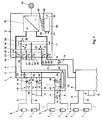
- FIG. 1 schematically illustrated photovoltaic system 1 are many details of a photovoltaic system, which are familiar to the expert, but are of no particular importance to the present invention, not shown. These include, for example, typically existing switches and fuses. Furthermore, components of the photovoltaic system, which are multiply present in a similar or even the same way, only indicated in their majority. In particular, the number of multiply existing components of the photovoltaic system 1 from the figure is not apparent. So an in Fig. 1 indicated plurality of one component to be much larger than an indicated plurality of another component, without this being apparent from the figure.
- the photovoltaic system 1 has an inverter 2. To the inverter 2, a plurality of busbars 5 are connected in parallel via a respective pair of manifolds 3, 4. To each current collecting unit 5, a plurality of strings 6 are connected in parallel with photovoltaic modules 7 connected in series via pairs of string lines 8 and 9. In the current collecting units 5 are the respective string lines 8 with the respective bus 3 and the respective string lines 9 with the respective bus 4 connected.
- switches not shown here may be provided to the string lines 8, 9 z. B. in pairs to the manifolds 3, 4 switch.
- the busbars 3 from the individual power-collecting units 5 are connected in a corresponding manner to a busbar 10 and the busbars 4 from the current-collecting units 5 to a busbar 11.
- a DC / AC converter 12 Connected to the busbars 10 and 11 is a DC / AC converter 12, which converts the direct current generated by the photovoltaic modules 7 into an alternating current, which it feeds, for example, into an alternating current network 13.
- a plurality of DC / AC converters may be connected in parallel to the busbars 10 and 11, for example a DC / AC converter per phase of a three-phase alternating current fed into the AC mains 13.
- the number of current collecting units 5 is typically smaller than the number of strings 6 per current collecting unit 5. However, this need not be so. These numbers may also be the same, or more current collecting units 5 may be provided as strings 6 per current collecting unit 5.
- Photovoltaic system 1 shown by way of example are no DC / DC converters between the strings 6 and the DC / AC converter 12. Due to this, basically, equal voltages occur between each pair of string lines 8 and 9, each pair of bus bars 3 and 4, and the bus bars 10 and 11. However, with each parallel connection of strings 6 and current collecting units 5, the current intensities increase.
- the risk that occur in insulation faults between conductors or against earth arcs 14 in the photovoltaic system 1, is given by the everywhere the same size and typically a few hundred to a few thousand volts amount of voltage anywhere.
- arcs 14 which are also referred to as parallel arcs, there is also a risk of (in Fig.
- each string of strings 8 and 9 is detected by means of a current sensor 15 and a voltage sensor 16; which is provided here for the string lines 8 and 9 of each string 6.
- a current sensor 15 and / or a voltage sensor 16 is sufficient for each of a plurality of pairs of optional (and in Fig.
- Vorsammel Oberen to which a plurality of strings 6 are connected and which are connected in parallel to the manifolds 3, 4, or even a current sensor 15 and / or a voltage sensor 16 for the manifolds 3, 4 of each
- all of the current sensors 15 and voltage sensors 16 are arranged on a side of a terminating capacitance 31 in the respective current collecting unit 5, which is formed by a capacitor connected between the busbars 4 and 5 and that for arcs 14 in the region of Strings 6 and their string lines 8 and 9 provides a low impedance.
- the current sensors 15 and the voltage sensors 16 can provide the measured values of electrical quantities they have acquired with time stamps which indicate the times at which the individual measured values were detected.
- an arc signal 20 is output by the analysis device 17.
- the arc signal 20 may initiate measures for extinguishing the arc and / or give a warning to the operator of the photovoltaic system 1.
- structure-borne sound sensors 21 and 22 are provided on the busbars 3 and 4 and structure-borne sound sensors 23 and 24 on the busbars 10 and 11.
- the structure-borne sound sensors 21 to 24 are in the in Fig. 1 embodiment shown all arranged in the inverter 2.
- at least the structure-borne sound sensors 21 and 22 could advantageously also be arranged in the current collecting units 5, because it is generally quieter in comparison to the interior of the inverter 2 because of less noise.
- the Structure-borne noise sensors 21 to 24 may provide the measured values of acoustic quantities they have acquired with time stamps which indicate the times at which the individual measured values were recorded.
- the structure-borne sound sensors 21 and 22 directly detect structure-borne sound vibrations of the busbars 3 and 4 and output measured values 25 and 26 with respect to frequency and amplitude of these structure-borne sound vibrations, which are optionally provided with time stamps.
- the structure-borne sound sensors 23 and 24 detect structure-borne sound vibrations of the busbars 10 and 11 and thus indirectly also structure-borne sound vibrations of the busbars 3 and 4 and output measured values 27 and 28 indicating the frequency and amplitude of the structure-borne sound vibrations of the busbars 10 and 11.
- the measured values 25 to 28 are analyzed by an analysis device 29 which, when indications of an arc 14 fulfill predetermined criteria, outputs an arc signal 30.
- the detection device for arcs in the photovoltaic system 1 thus comprises the sensors 15 and 16 and the analysis device 17 in the individual current collecting units 5 and the structure-borne sound sensors 21 to 24 and the analysis device 29.
- the illustrated local assignment of the structure-borne sound sensors 21 to 24 as well as the analysis devices 17 and 29 is to be understood as illustrative and not limiting.
- individual or all of the structure-borne sound sensors 21, 22 for the busbars 3, 4 may be arranged in the corresponding current collecting units 5.
- the individual sensors differ not only in their location but also in the quantities for which they acquire measured values.
- the structure-borne sound sensors 21 to 24 can be designed identically for differently dimensioned inverters 2 because of their measurement principle independent of the electrical variables. In other words, they do not have to be designed differently for an inverter designed for higher performance than for an inverter 2 designed for lower power. Furthermore, it is found that the measured values 25 to 28 provided by the structure-borne sound sensors 21 to 24 are suitable, both series-produced also to detect parallel arcs 14 safe, and this even with very long buses 3 and 4. In their entirety, the detection device for arcs 14 of the photovoltaic system 1 according to Fig. 1 therefore suitable to reliably detect arcs 14 occurring at any point of the photovoltaic system 1.
- the analysis devices 17 and 29 can also be combined or cooperate in order to detect arcs 14 by indications in the measured values 18 and 19 of the sensors 15 and 16 as well as by indications in the measured values 25 to 28 of the structure-borne sound sensors 21 to 24.
- both the measured values 18, 19 of the electrical quantities, the measured values 25 to 28 of the acoustic quantities and / or the arc signals 20, 30 can be transmitted between the analysis devices 17 and 29 or between the communication devices via a communication device (not shown in detail) Power collecting units 5 and the inverter 2 are transmitted.
- Fig. 1 the arcing detection device according to the invention in a photovoltaic system has been explained using the example of a photovoltaic system 1 which has no DC / DC converters between the strings 6 and the DC / AC converter 12, and thus in principle equal voltages between each pair of string lines 8 and 9, each pair of busbars 3 and 4 and the busbars 10 and 11 occur.
- the detection device according to the invention as well as the method according to the invention is not limited to such a photovoltaic system, but can also be applied to photovoltaic systems which have one or more DC / DC converters between the strings 6 and the DC / AC converter 12.
- different voltages between the string lines 8 and 9, the busbars 3 and 4 and the current busbars 10 and 11 prevail in these photovoltaic systems.
Landscapes
- Engineering & Computer Science (AREA)
- Power Engineering (AREA)
- Photovoltaic Devices (AREA)
- Inverter Devices (AREA)
- Life Sciences & Earth Sciences (AREA)
- Sustainable Development (AREA)
- Sustainable Energy (AREA)
- Measurement Of Mechanical Vibrations Or Ultrasonic Waves (AREA)
Priority Applications (5)
| Application Number | Priority Date | Filing Date | Title |
|---|---|---|---|
| EP14184145.2A EP2996157B1 (de) | 2014-09-09 | 2014-09-09 | Verfahren zum Detektieren von und Detektionsvorrichtung für Lichtbögen in einer Photovoltaikanlage |
| PCT/EP2015/069936 WO2016037897A1 (de) | 2014-09-09 | 2015-09-01 | Verfahren zum detektieren von und detektionsvorrichtung für lichtbögen in einer photovoltaikanlage |
| JP2017503890A JP6704898B2 (ja) | 2014-09-09 | 2015-09-01 | 光起電力システムにおけるアークを検出するための方法およびアークの検出装置 |
| CN201580048636.6A CN106716823B (zh) | 2014-09-09 | 2015-09-01 | 用于探测光伏设备中的电弧的方法和用于光伏设备中的电弧的探测设备以及光伏设备 |
| US15/454,189 US10581377B2 (en) | 2014-09-09 | 2017-03-09 | Method for detecting arcs, and detection apparatus for arcs, in a photovoltaic system |
Applications Claiming Priority (1)
| Application Number | Priority Date | Filing Date | Title |
|---|---|---|---|
| EP14184145.2A EP2996157B1 (de) | 2014-09-09 | 2014-09-09 | Verfahren zum Detektieren von und Detektionsvorrichtung für Lichtbögen in einer Photovoltaikanlage |
Publications (2)
| Publication Number | Publication Date |
|---|---|
| EP2996157A1 EP2996157A1 (de) | 2016-03-16 |
| EP2996157B1 true EP2996157B1 (de) | 2016-05-25 |
Family
ID=51492263
Family Applications (1)
| Application Number | Title | Priority Date | Filing Date |
|---|---|---|---|
| EP14184145.2A Not-in-force EP2996157B1 (de) | 2014-09-09 | 2014-09-09 | Verfahren zum Detektieren von und Detektionsvorrichtung für Lichtbögen in einer Photovoltaikanlage |
Country Status (5)
| Country | Link |
|---|---|
| US (1) | US10581377B2 (enExample) |
| EP (1) | EP2996157B1 (enExample) |
| JP (1) | JP6704898B2 (enExample) |
| CN (1) | CN106716823B (enExample) |
| WO (1) | WO2016037897A1 (enExample) |
Families Citing this family (15)
| Publication number | Priority date | Publication date | Assignee | Title |
|---|---|---|---|---|
| DE102012024728A1 (de) * | 2012-12-18 | 2014-07-03 | Ellenberger & Poensgen Gmbh | Verfahren und Vorrichtung zur Überwachung einer elektrischen Anlage auf einen Rückstrom |
| US20170170662A1 (en) * | 2015-12-15 | 2017-06-15 | Marvin S. Keshner | Parallel-Connected Solar Panel Array System with Split Inverter |
| US11277000B2 (en) * | 2016-06-21 | 2022-03-15 | Mitsubishi Electric Corporation | DC electrical circuit protection apparatus and ARC detection method |
| JP6673237B2 (ja) * | 2017-01-23 | 2020-03-25 | オムロン株式会社 | アーク検出装置 |
| JP6658582B2 (ja) * | 2017-01-31 | 2020-03-04 | オムロン株式会社 | アーク検出装置 |
| JP6658586B2 (ja) * | 2017-02-03 | 2020-03-04 | オムロン株式会社 | アーク検出装置 |
| US10879854B2 (en) | 2018-01-26 | 2020-12-29 | Skyworks Solutions, Inc. | Universal memory-based model for nonlinear power amplifier behaviors |
| US10985695B2 (en) | 2018-08-28 | 2021-04-20 | Analog Devices International Unlimited Company | DC arc detection and photovoltaic plant profiling system |
| EP3855190B8 (de) * | 2020-01-27 | 2025-04-23 | Navispace GmbH | Schallbasierte strommessung |
| CN112636311B (zh) * | 2020-11-12 | 2021-11-12 | 中国南方电网有限责任公司超高压输电公司广州局 | 基于电压钳位原理的多端口限流断路器及故障切除方法 |
| CN113125905B (zh) * | 2021-05-18 | 2022-10-21 | 余昉 | 电弧故障检测装置、方法、设备以及存储介质 |
| US20240055998A1 (en) | 2022-08-11 | 2024-02-15 | Delta Electronics, Inc. | Photovoltaic inverter |
| CN115327315B (zh) * | 2022-08-12 | 2025-02-28 | 上海电机学院 | 基于声信号的直流电弧检测方法、系统、设备及存储介质 |
| CN121656752A (zh) * | 2024-09-13 | 2026-03-13 | 余昉 | 电弧故障检测电路、方法、设备、存储介质及程序产品 |
| EP4727010A1 (de) * | 2024-10-08 | 2026-04-15 | FRONIUS INTERNATIONAL GmbH | Sicherheitsvorrichtung für eine photovoltaik-anlage, wechselrichter, photovoltaik-anlage, und verfahren zum betreiben einer photovoltaik-anlage |
Family Cites Families (22)
| Publication number | Priority date | Publication date | Assignee | Title |
|---|---|---|---|---|
| JPS6182406A (ja) * | 1984-09-29 | 1986-04-26 | Toshiba Corp | 油入電器の監視装置 |
| JPH05223883A (ja) * | 1992-02-18 | 1993-09-03 | Sumitomo Electric Ind Ltd | 光ファイバによる部分放電検出方法 |
| DE19617243A1 (de) | 1996-04-30 | 1997-11-06 | Horstmann Gmbh Dipl Ing H | Verfahren und Vorrichtung zur Bestimmung des Abstandes eines Kabelfehlers |
| EP1623240B1 (de) | 2003-05-09 | 2008-04-09 | Siemens Aktiengesellschaft | Messeinrichtung und verfahren zur ortung einer teilentladung |
| US7403129B2 (en) * | 2006-05-10 | 2008-07-22 | Eaton Corporation | Electrical switching apparatus and method employing acoustic and current signals to distinguish between parallel and series arc faults |
| US8473250B2 (en) * | 2006-12-06 | 2013-06-25 | Solaredge, Ltd. | Monitoring of distributed power harvesting systems using DC power sources |
| FR2940459B1 (fr) * | 2008-12-22 | 2012-11-30 | Commissariat Energie Atomique | Procede de detection d'arc electrique dans une installation photovoltaique. |
| US8218274B2 (en) * | 2009-12-15 | 2012-07-10 | Eaton Corporation | Direct current arc fault circuit interrupter, direct current arc fault detector, noise blanking circuit for a direct current arc fault circuit interrupter, and method of detecting arc faults |
| DE102010026815A1 (de) | 2010-07-10 | 2012-01-12 | Hagenuk KMT Kabelmeßtechnik GmbH | Verfahren und Vorrichtung zur Ortung von Kabelfehlern |
| EP2710388B1 (en) * | 2011-05-20 | 2021-05-19 | SMA Solar Technology AG | Method and system for detecting an arc fault in a power circuit |
| US9008978B2 (en) * | 2011-06-17 | 2015-04-14 | Sunfield Semiconductor, Inc. | System and method for arc detection in solar power arrays |
| WO2013004295A1 (en) * | 2011-07-04 | 2013-01-10 | Sma Solar Technology Ag | Method and system for detecting an arc fault in a photovoltaic power system |
| FR2977677B1 (fr) * | 2011-07-04 | 2013-08-23 | Commissariat Energie Atomique | Detection d'arcs electriques dans les installations photovoltaiques |
| US9431825B2 (en) * | 2011-07-28 | 2016-08-30 | Tigo Energy, Inc. | Systems and methods to reduce the number and cost of management units of distributed power generators |
| JP5888972B2 (ja) * | 2011-12-22 | 2016-03-22 | 三菱電機株式会社 | 太陽光発電システム |
| JP5889143B2 (ja) * | 2012-08-21 | 2016-03-22 | 三菱電機株式会社 | 太陽光発電システムおよびアーク検出保護装置 |
| DE102012110687A1 (de) * | 2012-08-27 | 2014-05-15 | Newtos Ag | Verfahren zur Lichtbogenerkennung in Photovoltaikanlagen |
| US9057752B2 (en) * | 2012-09-11 | 2015-06-16 | Eaton Corporation | Method and apparatus for detecting a loose electrical connection in photovoltaic system |
| US9240682B2 (en) * | 2012-09-18 | 2016-01-19 | Sunpower Corporation | Mitigation of arc flash hazard in photovoltaic power plants |
| US9465909B2 (en) * | 2012-11-16 | 2016-10-11 | Sensata Technologies, Inc. | Systems and methods of discriminating DC arcs and load switching noise |
| US9304159B2 (en) * | 2013-01-08 | 2016-04-05 | Eaton Corporation | Detection and location of electrical connections having a micro-interface abnormality in an electrical system |
| JP6164848B2 (ja) * | 2013-01-10 | 2017-07-19 | 三菱電機株式会社 | アーク検出装置 |
-
2014
- 2014-09-09 EP EP14184145.2A patent/EP2996157B1/de not_active Not-in-force
-
2015
- 2015-09-01 WO PCT/EP2015/069936 patent/WO2016037897A1/de not_active Ceased
- 2015-09-01 CN CN201580048636.6A patent/CN106716823B/zh not_active Expired - Fee Related
- 2015-09-01 JP JP2017503890A patent/JP6704898B2/ja not_active Expired - Fee Related
-
2017
- 2017-03-09 US US15/454,189 patent/US10581377B2/en not_active Expired - Fee Related
Also Published As
| Publication number | Publication date |
|---|---|
| CN106716823A (zh) | 2017-05-24 |
| JP6704898B2 (ja) | 2020-06-03 |
| WO2016037897A1 (de) | 2016-03-17 |
| EP2996157A1 (de) | 2016-03-16 |
| CN106716823B (zh) | 2019-06-21 |
| US10581377B2 (en) | 2020-03-03 |
| JP2017529818A (ja) | 2017-10-05 |
| US20170179880A1 (en) | 2017-06-22 |
Similar Documents
| Publication | Publication Date | Title |
|---|---|---|
| EP2996157B1 (de) | Verfahren zum Detektieren von und Detektionsvorrichtung für Lichtbögen in einer Photovoltaikanlage | |
| EP2585841B1 (de) | Vorrichtung und verfahren zur überwachung einer photovoltaikanlage | |
| EP3968037B1 (de) | Verfahren und einrichtung zum ermitteln eines fehlerortes in einem elektrischen energieverteilnetz | |
| DE102012109749A1 (de) | Verfahren und Vorrichtung zum Erkennen eines Lichtbogens in einem Gleichstromkreis | |
| EP1090303B1 (de) | Verfahren und vorrichtung zur überwachung einer elektrodenleitung einer bipolaren hochspannungs-gleichstrom-übertragungs-anlage | |
| DE19644833C2 (de) | Vorrichtung zum Testen der Isolation eines elektrischen Leiters | |
| CH682770A5 (de) | Vorrichtung zum Prüfen der Isolierung eines elektrischen Leiters. | |
| EP3861359B1 (de) | Verfahren zum bestimmen eines kurzschlusses mit auftreten eines lichtbogens an einem elektrischen leiter | |
| DE102018114540B3 (de) | Verfahren zur Erkennung von Lichtbögen in Gleichstromkreisen | |
| DE102014109978A1 (de) | Verfahren, Schaltungsanordnung und Photovoltaikwechselrichter mit Mitteln zur Ableitstromkompensation in einer Photovoltaikanlage mit mehreren Differenzstromsensoren | |
| EP4127744B1 (de) | Elektrische schaltungsanordnung | |
| DE102014221108A1 (de) | Koppeleinrichtung zum Ankoppeln eines Powerline-Endgeräts und eines Messgeräts an ein Energieversorgungsnetzwerk sowie Messknoten | |
| DE202011110723U1 (de) | Schutzschalter | |
| DE102017112256A1 (de) | Verfahren zur erkennung eines kontaktfehlers in einer photovoltaikanlage | |
| EP3643579B1 (de) | Vorrichtung und verfahren zur überwachung einer weiche | |
| EP0917979B1 (de) | Verfahren zur Störstrom- und Zustandsüberwachung in Schienenfahrzeugen | |
| DE102017215006A1 (de) | Erkennen eines Fehlers in einem Gleichstromübertragungssystem | |
| DE102015200174A1 (de) | Vorrichtung zum Überwachen eines Bordnetzes | |
| WO2019179645A1 (de) | Verfahren sowie messanordnung zur erfassung eines elektromagnetischen störeinflusses auf einen leitungskern einer elektrischen leitung | |
| EP3462195B1 (de) | Prüfvorrichtung und prüfverfahren zum prüfen eines datenkabels für ein kraftfahrzeug mittels konstantstromquelle | |
| EP2329574B1 (de) | Verfahren und anordnung zum erzeugen eines fehlersignals | |
| DE102015009426A1 (de) | Verfahren zur Zustandsbestimmung und Fehlerortung an installierten isolierten Ableitungen im äußeren Blitzschutz | |
| DE102016108519A1 (de) | Nichtinvasive Lastbeobachtung | |
| WO2004102760A1 (de) | Verfahren und vorrichtung zur erkennung von störlichtbögen | |
| EP3300201A1 (de) | Verfahren und einrichtung zum überwachen einer energieübertragungseinrichtung |
Legal Events
| Date | Code | Title | Description |
|---|---|---|---|
| GRAP | Despatch of communication of intention to grant a patent |
Free format text: ORIGINAL CODE: EPIDOSNIGR1 |
|
| GRAS | Grant fee paid |
Free format text: ORIGINAL CODE: EPIDOSNIGR3 |
|
| PUAI | Public reference made under article 153(3) epc to a published international application that has entered the european phase |
Free format text: ORIGINAL CODE: 0009012 |
|
| 17P | Request for examination filed |
Effective date: 20150209 |
|
| AK | Designated contracting states |
Kind code of ref document: A1 Designated state(s): AL AT BE BG CH CY CZ DE DK EE ES FI FR GB GR HR HU IE IS IT LI LT LU LV MC MK MT NL NO PL PT RO RS SE SI SK SM TR |
|
| GRAA | (expected) grant |
Free format text: ORIGINAL CODE: 0009210 |
|
| RBV | Designated contracting states (corrected) |
Designated state(s): AL AT BE BG CH CY CZ DE DK EE ES FI FR GB GR HR HU IE IS IT LI LT LU LV MC MK MT NL NO PL PT RO RS SE SI SK SM TR |
|
| AK | Designated contracting states |
Kind code of ref document: B1 Designated state(s): AL AT BE BG CH CY CZ DE DK EE ES FI FR GB GR HR HU IE IS IT LI LT LU LV MC MK MT NL NO PL PT RO RS SE SI SK SM TR |
|
| REG | Reference to a national code |
Ref country code: GB Ref legal event code: FG4D Free format text: NOT ENGLISH |
|
| REG | Reference to a national code |
Ref country code: CH Ref legal event code: EP |
|
| REG | Reference to a national code |
Ref country code: IE Ref legal event code: FG4D Free format text: LANGUAGE OF EP DOCUMENT: GERMAN Ref country code: AT Ref legal event code: REF Ref document number: 802964 Country of ref document: AT Kind code of ref document: T Effective date: 20160615 |
|
| REG | Reference to a national code |
Ref country code: DE Ref legal event code: R096 Ref document number: 502014000846 Country of ref document: DE |
|
| REG | Reference to a national code |
Ref country code: FR Ref legal event code: PLFP Year of fee payment: 3 |
|
| REG | Reference to a national code |
Ref country code: LT Ref legal event code: MG4D |
|
| REG | Reference to a national code |
Ref country code: NL Ref legal event code: MP Effective date: 20160525 |
|
| PG25 | Lapsed in a contracting state [announced via postgrant information from national office to epo] |
Ref country code: LT Free format text: LAPSE BECAUSE OF FAILURE TO SUBMIT A TRANSLATION OF THE DESCRIPTION OR TO PAY THE FEE WITHIN THE PRESCRIBED TIME-LIMIT Effective date: 20160525 Ref country code: FI Free format text: LAPSE BECAUSE OF FAILURE TO SUBMIT A TRANSLATION OF THE DESCRIPTION OR TO PAY THE FEE WITHIN THE PRESCRIBED TIME-LIMIT Effective date: 20160525 Ref country code: NO Free format text: LAPSE BECAUSE OF FAILURE TO SUBMIT A TRANSLATION OF THE DESCRIPTION OR TO PAY THE FEE WITHIN THE PRESCRIBED TIME-LIMIT Effective date: 20160825 Ref country code: NL Free format text: LAPSE BECAUSE OF FAILURE TO SUBMIT A TRANSLATION OF THE DESCRIPTION OR TO PAY THE FEE WITHIN THE PRESCRIBED TIME-LIMIT Effective date: 20160525 |
|
| PG25 | Lapsed in a contracting state [announced via postgrant information from national office to epo] |
Ref country code: SE Free format text: LAPSE BECAUSE OF FAILURE TO SUBMIT A TRANSLATION OF THE DESCRIPTION OR TO PAY THE FEE WITHIN THE PRESCRIBED TIME-LIMIT Effective date: 20160525 Ref country code: ES Free format text: LAPSE BECAUSE OF FAILURE TO SUBMIT A TRANSLATION OF THE DESCRIPTION OR TO PAY THE FEE WITHIN THE PRESCRIBED TIME-LIMIT Effective date: 20160525 Ref country code: PT Free format text: LAPSE BECAUSE OF FAILURE TO SUBMIT A TRANSLATION OF THE DESCRIPTION OR TO PAY THE FEE WITHIN THE PRESCRIBED TIME-LIMIT Effective date: 20160926 Ref country code: LV Free format text: LAPSE BECAUSE OF FAILURE TO SUBMIT A TRANSLATION OF THE DESCRIPTION OR TO PAY THE FEE WITHIN THE PRESCRIBED TIME-LIMIT Effective date: 20160525 Ref country code: RS Free format text: LAPSE BECAUSE OF FAILURE TO SUBMIT A TRANSLATION OF THE DESCRIPTION OR TO PAY THE FEE WITHIN THE PRESCRIBED TIME-LIMIT Effective date: 20160525 Ref country code: GR Free format text: LAPSE BECAUSE OF FAILURE TO SUBMIT A TRANSLATION OF THE DESCRIPTION OR TO PAY THE FEE WITHIN THE PRESCRIBED TIME-LIMIT Effective date: 20160826 |
|
| PG25 | Lapsed in a contracting state [announced via postgrant information from national office to epo] |
Ref country code: RO Free format text: LAPSE BECAUSE OF FAILURE TO SUBMIT A TRANSLATION OF THE DESCRIPTION OR TO PAY THE FEE WITHIN THE PRESCRIBED TIME-LIMIT Effective date: 20160525 Ref country code: EE Free format text: LAPSE BECAUSE OF FAILURE TO SUBMIT A TRANSLATION OF THE DESCRIPTION OR TO PAY THE FEE WITHIN THE PRESCRIBED TIME-LIMIT Effective date: 20160525 Ref country code: DK Free format text: LAPSE BECAUSE OF FAILURE TO SUBMIT A TRANSLATION OF THE DESCRIPTION OR TO PAY THE FEE WITHIN THE PRESCRIBED TIME-LIMIT Effective date: 20160525 Ref country code: CZ Free format text: LAPSE BECAUSE OF FAILURE TO SUBMIT A TRANSLATION OF THE DESCRIPTION OR TO PAY THE FEE WITHIN THE PRESCRIBED TIME-LIMIT Effective date: 20160525 Ref country code: SK Free format text: LAPSE BECAUSE OF FAILURE TO SUBMIT A TRANSLATION OF THE DESCRIPTION OR TO PAY THE FEE WITHIN THE PRESCRIBED TIME-LIMIT Effective date: 20160525 |
|
| PG25 | Lapsed in a contracting state [announced via postgrant information from national office to epo] |
Ref country code: BE Free format text: LAPSE BECAUSE OF NON-PAYMENT OF DUE FEES Effective date: 20160930 Ref country code: PL Free format text: LAPSE BECAUSE OF FAILURE TO SUBMIT A TRANSLATION OF THE DESCRIPTION OR TO PAY THE FEE WITHIN THE PRESCRIBED TIME-LIMIT Effective date: 20160525 Ref country code: SM Free format text: LAPSE BECAUSE OF FAILURE TO SUBMIT A TRANSLATION OF THE DESCRIPTION OR TO PAY THE FEE WITHIN THE PRESCRIBED TIME-LIMIT Effective date: 20160525 |
|
| REG | Reference to a national code |
Ref country code: DE Ref legal event code: R097 Ref document number: 502014000846 Country of ref document: DE |
|
| PLBE | No opposition filed within time limit |
Free format text: ORIGINAL CODE: 0009261 |
|
| STAA | Information on the status of an ep patent application or granted ep patent |
Free format text: STATUS: NO OPPOSITION FILED WITHIN TIME LIMIT |
|
| PG25 | Lapsed in a contracting state [announced via postgrant information from national office to epo] |
Ref country code: MC Free format text: LAPSE BECAUSE OF FAILURE TO SUBMIT A TRANSLATION OF THE DESCRIPTION OR TO PAY THE FEE WITHIN THE PRESCRIBED TIME-LIMIT Effective date: 20160525 |
|
| 26N | No opposition filed |
Effective date: 20170228 |
|
| PG25 | Lapsed in a contracting state [announced via postgrant information from national office to epo] |
Ref country code: SI Free format text: LAPSE BECAUSE OF FAILURE TO SUBMIT A TRANSLATION OF THE DESCRIPTION OR TO PAY THE FEE WITHIN THE PRESCRIBED TIME-LIMIT Effective date: 20160525 |
|
| REG | Reference to a national code |
Ref country code: IE Ref legal event code: MM4A |
|
| PG25 | Lapsed in a contracting state [announced via postgrant information from national office to epo] |
Ref country code: IE Free format text: LAPSE BECAUSE OF NON-PAYMENT OF DUE FEES Effective date: 20160909 |
|
| PG25 | Lapsed in a contracting state [announced via postgrant information from national office to epo] |
Ref country code: LU Free format text: LAPSE BECAUSE OF NON-PAYMENT OF DUE FEES Effective date: 20160909 |
|
| REG | Reference to a national code |
Ref country code: FR Ref legal event code: PLFP Year of fee payment: 4 |
|
| REG | Reference to a national code |
Ref country code: BE Ref legal event code: MM Effective date: 20160930 |
|
| REG | Reference to a national code |
Ref country code: CH Ref legal event code: PL |
|
| PG25 | Lapsed in a contracting state [announced via postgrant information from national office to epo] |
Ref country code: HU Free format text: LAPSE BECAUSE OF FAILURE TO SUBMIT A TRANSLATION OF THE DESCRIPTION OR TO PAY THE FEE WITHIN THE PRESCRIBED TIME-LIMIT; INVALID AB INITIO Effective date: 20140909 |
|
| PG25 | Lapsed in a contracting state [announced via postgrant information from national office to epo] |
Ref country code: CY Free format text: LAPSE BECAUSE OF FAILURE TO SUBMIT A TRANSLATION OF THE DESCRIPTION OR TO PAY THE FEE WITHIN THE PRESCRIBED TIME-LIMIT Effective date: 20160525 Ref country code: IS Free format text: LAPSE BECAUSE OF FAILURE TO SUBMIT A TRANSLATION OF THE DESCRIPTION OR TO PAY THE FEE WITHIN THE PRESCRIBED TIME-LIMIT Effective date: 20160525 Ref country code: HR Free format text: LAPSE BECAUSE OF FAILURE TO SUBMIT A TRANSLATION OF THE DESCRIPTION OR TO PAY THE FEE WITHIN THE PRESCRIBED TIME-LIMIT Effective date: 20160525 Ref country code: MK Free format text: LAPSE BECAUSE OF FAILURE TO SUBMIT A TRANSLATION OF THE DESCRIPTION OR TO PAY THE FEE WITHIN THE PRESCRIBED TIME-LIMIT Effective date: 20160525 Ref country code: MT Free format text: LAPSE BECAUSE OF FAILURE TO SUBMIT A TRANSLATION OF THE DESCRIPTION OR TO PAY THE FEE WITHIN THE PRESCRIBED TIME-LIMIT Effective date: 20160525 |
|
| PG25 | Lapsed in a contracting state [announced via postgrant information from national office to epo] |
Ref country code: BG Free format text: LAPSE BECAUSE OF FAILURE TO SUBMIT A TRANSLATION OF THE DESCRIPTION OR TO PAY THE FEE WITHIN THE PRESCRIBED TIME-LIMIT Effective date: 20160525 Ref country code: LI Free format text: LAPSE BECAUSE OF NON-PAYMENT OF DUE FEES Effective date: 20170930 Ref country code: CH Free format text: LAPSE BECAUSE OF NON-PAYMENT OF DUE FEES Effective date: 20170930 |
|
| REG | Reference to a national code |
Ref country code: FR Ref legal event code: PLFP Year of fee payment: 5 |
|
| PG25 | Lapsed in a contracting state [announced via postgrant information from national office to epo] |
Ref country code: TR Free format text: LAPSE BECAUSE OF FAILURE TO SUBMIT A TRANSLATION OF THE DESCRIPTION OR TO PAY THE FEE WITHIN THE PRESCRIBED TIME-LIMIT Effective date: 20160525 Ref country code: AL Free format text: LAPSE BECAUSE OF FAILURE TO SUBMIT A TRANSLATION OF THE DESCRIPTION OR TO PAY THE FEE WITHIN THE PRESCRIBED TIME-LIMIT Effective date: 20160525 |
|
| REG | Reference to a national code |
Ref country code: AT Ref legal event code: MM01 Ref document number: 802964 Country of ref document: AT Kind code of ref document: T Effective date: 20190909 |
|
| PG25 | Lapsed in a contracting state [announced via postgrant information from national office to epo] |
Ref country code: AT Free format text: LAPSE BECAUSE OF NON-PAYMENT OF DUE FEES Effective date: 20190909 |
|
| PGFP | Annual fee paid to national office [announced via postgrant information from national office to epo] |
Ref country code: GB Payment date: 20220927 Year of fee payment: 9 Ref country code: DE Payment date: 20220920 Year of fee payment: 9 |
|
| PGFP | Annual fee paid to national office [announced via postgrant information from national office to epo] |
Ref country code: FR Payment date: 20220920 Year of fee payment: 9 |
|
| PGFP | Annual fee paid to national office [announced via postgrant information from national office to epo] |
Ref country code: IT Payment date: 20220930 Year of fee payment: 9 |
|
| REG | Reference to a national code |
Ref country code: DE Ref legal event code: R119 Ref document number: 502014000846 Country of ref document: DE |
|
| GBPC | Gb: european patent ceased through non-payment of renewal fee |
Effective date: 20230909 |
|
| PG25 | Lapsed in a contracting state [announced via postgrant information from national office to epo] |
Ref country code: GB Free format text: LAPSE BECAUSE OF NON-PAYMENT OF DUE FEES Effective date: 20230909 |
|
| PG25 | Lapsed in a contracting state [announced via postgrant information from national office to epo] |
Ref country code: GB Free format text: LAPSE BECAUSE OF NON-PAYMENT OF DUE FEES Effective date: 20230909 Ref country code: FR Free format text: LAPSE BECAUSE OF NON-PAYMENT OF DUE FEES Effective date: 20230930 Ref country code: DE Free format text: LAPSE BECAUSE OF NON-PAYMENT OF DUE FEES Effective date: 20240403 |
|
| PG25 | Lapsed in a contracting state [announced via postgrant information from national office to epo] |
Ref country code: IT Free format text: LAPSE BECAUSE OF NON-PAYMENT OF DUE FEES Effective date: 20230909 |
|
| PG25 | Lapsed in a contracting state [announced via postgrant information from national office to epo] |
Ref country code: IT Free format text: LAPSE BECAUSE OF NON-PAYMENT OF DUE FEES Effective date: 20230909 |