EP2995835B1 - Verfahren zur steuerung eines automatischen schaltgetriebes und steuergerät - Google Patents
Verfahren zur steuerung eines automatischen schaltgetriebes und steuergerät Download PDFInfo
- Publication number
- EP2995835B1 EP2995835B1 EP15001327.4A EP15001327A EP2995835B1 EP 2995835 B1 EP2995835 B1 EP 2995835B1 EP 15001327 A EP15001327 A EP 15001327A EP 2995835 B1 EP2995835 B1 EP 2995835B1
- Authority
- EP
- European Patent Office
- Prior art keywords
- shift
- engine
- temperature
- vehicle
- exhaust
- Prior art date
- Legal status (The legal status is an assumption and is not a legal conclusion. Google has not performed a legal analysis and makes no representation as to the accuracy of the status listed.)
- Active
Links
Images
Classifications
-
- F—MECHANICAL ENGINEERING; LIGHTING; HEATING; WEAPONS; BLASTING
- F16—ENGINEERING ELEMENTS AND UNITS; GENERAL MEASURES FOR PRODUCING AND MAINTAINING EFFECTIVE FUNCTIONING OF MACHINES OR INSTALLATIONS; THERMAL INSULATION IN GENERAL
- F16H—GEARING
- F16H61/00—Control functions within control units of change-speed- or reversing-gearings for conveying rotary motion ; Control of exclusively fluid gearing, friction gearing, gearings with endless flexible members or other particular types of gearing
- F16H61/02—Control functions within control units of change-speed- or reversing-gearings for conveying rotary motion ; Control of exclusively fluid gearing, friction gearing, gearings with endless flexible members or other particular types of gearing characterised by the signals used
- F16H61/0202—Control functions within control units of change-speed- or reversing-gearings for conveying rotary motion ; Control of exclusively fluid gearing, friction gearing, gearings with endless flexible members or other particular types of gearing characterised by the signals used the signals being electric
- F16H61/0204—Control functions within control units of change-speed- or reversing-gearings for conveying rotary motion ; Control of exclusively fluid gearing, friction gearing, gearings with endless flexible members or other particular types of gearing characterised by the signals used the signals being electric for gearshift control, e.g. control functions for performing shifting or generation of shift signal
- F16H61/0213—Control functions within control units of change-speed- or reversing-gearings for conveying rotary motion ; Control of exclusively fluid gearing, friction gearing, gearings with endless flexible members or other particular types of gearing characterised by the signals used the signals being electric for gearshift control, e.g. control functions for performing shifting or generation of shift signal characterised by the method for generating shift signals
-
- F—MECHANICAL ENGINEERING; LIGHTING; HEATING; WEAPONS; BLASTING
- F16—ENGINEERING ELEMENTS AND UNITS; GENERAL MEASURES FOR PRODUCING AND MAINTAINING EFFECTIVE FUNCTIONING OF MACHINES OR INSTALLATIONS; THERMAL INSULATION IN GENERAL
- F16H—GEARING
- F16H59/00—Control inputs to control units of change-speed- or reversing-gearings for conveying rotary motion
- F16H59/74—Inputs being a function of engine parameters
- F16H59/78—Temperature
-
- F—MECHANICAL ENGINEERING; LIGHTING; HEATING; WEAPONS; BLASTING
- F16—ENGINEERING ELEMENTS AND UNITS; GENERAL MEASURES FOR PRODUCING AND MAINTAINING EFFECTIVE FUNCTIONING OF MACHINES OR INSTALLATIONS; THERMAL INSULATION IN GENERAL
- F16H—GEARING
- F16H61/00—Control functions within control units of change-speed- or reversing-gearings for conveying rotary motion ; Control of exclusively fluid gearing, friction gearing, gearings with endless flexible members or other particular types of gearing
- F16H2061/0015—Transmission control for optimising fuel consumptions
-
- F—MECHANICAL ENGINEERING; LIGHTING; HEATING; WEAPONS; BLASTING
- F16—ENGINEERING ELEMENTS AND UNITS; GENERAL MEASURES FOR PRODUCING AND MAINTAINING EFFECTIVE FUNCTIONING OF MACHINES OR INSTALLATIONS; THERMAL INSULATION IN GENERAL
- F16H—GEARING
- F16H61/00—Control functions within control units of change-speed- or reversing-gearings for conveying rotary motion ; Control of exclusively fluid gearing, friction gearing, gearings with endless flexible members or other particular types of gearing
- F16H61/02—Control functions within control units of change-speed- or reversing-gearings for conveying rotary motion ; Control of exclusively fluid gearing, friction gearing, gearings with endless flexible members or other particular types of gearing characterised by the signals used
- F16H61/0202—Control functions within control units of change-speed- or reversing-gearings for conveying rotary motion ; Control of exclusively fluid gearing, friction gearing, gearings with endless flexible members or other particular types of gearing characterised by the signals used the signals being electric
- F16H61/0204—Control functions within control units of change-speed- or reversing-gearings for conveying rotary motion ; Control of exclusively fluid gearing, friction gearing, gearings with endless flexible members or other particular types of gearing characterised by the signals used the signals being electric for gearshift control, e.g. control functions for performing shifting or generation of shift signal
- F16H61/0213—Control functions within control units of change-speed- or reversing-gearings for conveying rotary motion ; Control of exclusively fluid gearing, friction gearing, gearings with endless flexible members or other particular types of gearing characterised by the signals used the signals being electric for gearshift control, e.g. control functions for performing shifting or generation of shift signal characterised by the method for generating shift signals
- F16H2061/0216—Calculation or estimation of post shift values for different gear ratios, e.g. by using engine performance tables
-
- F—MECHANICAL ENGINEERING; LIGHTING; HEATING; WEAPONS; BLASTING
- F16—ENGINEERING ELEMENTS AND UNITS; GENERAL MEASURES FOR PRODUCING AND MAINTAINING EFFECTIVE FUNCTIONING OF MACHINES OR INSTALLATIONS; THERMAL INSULATION IN GENERAL
- F16H—GEARING
- F16H61/00—Control functions within control units of change-speed- or reversing-gearings for conveying rotary motion ; Control of exclusively fluid gearing, friction gearing, gearings with endless flexible members or other particular types of gearing
- F16H61/02—Control functions within control units of change-speed- or reversing-gearings for conveying rotary motion ; Control of exclusively fluid gearing, friction gearing, gearings with endless flexible members or other particular types of gearing characterised by the signals used
- F16H61/0202—Control functions within control units of change-speed- or reversing-gearings for conveying rotary motion ; Control of exclusively fluid gearing, friction gearing, gearings with endless flexible members or other particular types of gearing characterised by the signals used the signals being electric
- F16H61/0204—Control functions within control units of change-speed- or reversing-gearings for conveying rotary motion ; Control of exclusively fluid gearing, friction gearing, gearings with endless flexible members or other particular types of gearing characterised by the signals used the signals being electric for gearshift control, e.g. control functions for performing shifting or generation of shift signal
- F16H61/0213—Control functions within control units of change-speed- or reversing-gearings for conveying rotary motion ; Control of exclusively fluid gearing, friction gearing, gearings with endless flexible members or other particular types of gearing characterised by the signals used the signals being electric for gearshift control, e.g. control functions for performing shifting or generation of shift signal characterised by the method for generating shift signals
- F16H2061/022—Calculation or estimation of optimal gear ratio, e.g. best ratio for economy drive or performance according driver preference, or to optimise exhaust emissions
-
- F—MECHANICAL ENGINEERING; LIGHTING; HEATING; WEAPONS; BLASTING
- F16—ENGINEERING ELEMENTS AND UNITS; GENERAL MEASURES FOR PRODUCING AND MAINTAINING EFFECTIVE FUNCTIONING OF MACHINES OR INSTALLATIONS; THERMAL INSULATION IN GENERAL
- F16H—GEARING
- F16H61/00—Control functions within control units of change-speed- or reversing-gearings for conveying rotary motion ; Control of exclusively fluid gearing, friction gearing, gearings with endless flexible members or other particular types of gearing
- F16H61/02—Control functions within control units of change-speed- or reversing-gearings for conveying rotary motion ; Control of exclusively fluid gearing, friction gearing, gearings with endless flexible members or other particular types of gearing characterised by the signals used
- F16H61/0202—Control functions within control units of change-speed- or reversing-gearings for conveying rotary motion ; Control of exclusively fluid gearing, friction gearing, gearings with endless flexible members or other particular types of gearing characterised by the signals used the signals being electric
- F16H61/0204—Control functions within control units of change-speed- or reversing-gearings for conveying rotary motion ; Control of exclusively fluid gearing, friction gearing, gearings with endless flexible members or other particular types of gearing characterised by the signals used the signals being electric for gearshift control, e.g. control functions for performing shifting or generation of shift signal
- F16H61/0213—Control functions within control units of change-speed- or reversing-gearings for conveying rotary motion ; Control of exclusively fluid gearing, friction gearing, gearings with endless flexible members or other particular types of gearing characterised by the signals used the signals being electric for gearshift control, e.g. control functions for performing shifting or generation of shift signal characterised by the method for generating shift signals
- F16H2061/0232—Selecting ratios for bringing engine into a particular state, e.g. for fast warming up or for reducing exhaust emissions
Definitions
- the invention relates to a method for controlling a shifting process of an automatic gearbox in a vehicle with an internal combustion engine as the motor according to the preamble of claim 1, a control device for carrying out the method, and a vehicle.
- a target gear of the transmission is determined as a function of various parameters and a shift command is automatically executed when the specified shift conditions are reached.
- the criteria for such an automatic shifting process are, in particular, an operation of the vehicle that is as fuel-efficient as possible.
- a shift strategy is specified in a control unit in which the behavior of the engine after a possible shift into a target gear is continuously and predictively determined on the basis of currently recorded driving dynamics and / or vehicle-specific and / or engine-specific actual values.
- An engine speed, an output speed of the transmission, an accelerator pedal position, a brake pedal position and a driving speed are used here as actual values for calculating such a forecast result.
- An accelerator pedal speed, a current vehicle mass and a road gradient can also be taken into account here.
- adjusted switching thresholds are used as upshift thresholds or downshift thresholds, in particular for a fuel-efficient shifting is determined and specified, with a control command for a corresponding automatic shifting process being output after such a switching threshold is exceeded.
- basic limit speed ranges are defined as switching thresholds, which can be shifted in terms of their limits and adapted to the respective current conditions.
- the decision as to whether a shift will be fuel-efficient or not, and thus whether fuel savings can be realized depends on how precisely a predictive determination of the behavior of the engine, in particular a torque build-up after a possible shift into a target gear, can be determined.
- a control method for an automatic transmission is also known ( DE 10 2005 050 479 A1 ), in which the behavior of the engine with regard to the anticipated engine speed after a shift into a target gear is calculated in advance of a shift. This calculated engine speed is compared with a downshift threshold and an automatic upshift into the target gear is only implemented when such a downshift threshold is exceeded.
- DE 601 02 962 T2 a similar known control method
- an engine speed is also calculated in advance for a possible target gear and an upshift is only implemented if a maximum permissible engine speed is not exceeded.
- the WO 2014/055017 A1 shows a generic method wherein the temperature in an exhaust gas stream is controlled by upshifting to a higher gear or downshifting to a lower gear.
- a method is proposed in which a switching strategy is specified in a control unit in which, on the basis of currently recorded vehicle-specific and / or vehicle-specific and / or engine-specific actual values, the behavior of the engine after a possible switching operation is continuously and predictively Target gear is determined, with the inclusion of these preview results, adjusted shift thresholds as upshift thresholds or downshift thresholds, in particular for a fuel-efficient shift, determined and specified, with a control command for a corresponding automatic shifting process being output after a shift threshold is exceeded.
- the current temperature of at least one component of the engine exhaust system is also taken into account when specifying an adapted switching threshold.
- the current thermal state of the engine exhaust system for example the thermal state of an exhaust gas turbine of a turbocharger, has a decisive influence on the step response of the engine during a switching process. If such a thermal state is taken into account in the predictive calculation of the behavior of the engine after a shift into a target gear, the predictive result is more precise and a decision for a fuel-efficient shift can advantageously be made more precisely.
- the relevant thermal state is preferably determined with respect to an exhaust gas turbine of an exhaust gas turbocharger, but can also alternatively or additionally be related to an exhaust manifold.
- the relevant temperature of an exhaust system component can be measured directly by means of one or more temperature sensors, a current temperature signal then being fed to the control unit.
- a temperature measurement known measurement methods with sensors lying on the component or as non-contact measurements are available.
- the relevant temperature, in particular of an exhaust gas turbine can be calculated indirectly via the load profile of the internal combustion engine before a switching process.
- the speed and / or the boost pressure and / or the injection quantity and / or the air mass flow of the internal combustion engine can be used for such a calculation.
- a torque build-up is calculated in advance as a load step response of the internal combustion engine. It is preferably provided that a component temperature that is lower than a defined component temperature threshold value causes a slower torque build-up with correspondingly lower power of the internal combustion engine than is the case with component temperatures corresponding to or higher than the defined component threshold temperature. This means that a relatively lower component temperature results in a slower torque build-up with a correspondingly lower output of the internal combustion engine.
- the internal combustion engine when specifying a switching threshold and making a decision for a switching process, it is then taken into account how quickly and with what time curve under the current temperature condition, in particular on an exhaust gas turbine, the internal combustion engine provides the required power for the current speed requirement of the vehicle.
- a control device for performing one of the above methods is also claimed, as well as a vehicle, in particular a commercial vehicle, using such a control device.
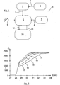
- FIG. 1 shows a flow chart 1 for a method for controlling a shifting process of an automatic gearbox in a vehicle with an internal combustion engine as the motor.
- the actual state of the motor is continuously determined in block 2, with input variables recorded as being shown schematically with block 3 and input arrow 4 being used for the calculation.
- the fuel and air supply, the water temperature and, if necessary, other recorded variables are used as input variables for this purpose.
- Block 6 Based on the results from block 2 (input arrow 5), a precalculation of the torque build-up for possible map points of a possible target gear is carried out in block 6.
- further input variables are used and taken into account, as shown schematically with block 7 and input arrow 8.
- Block 7 stands schematically for the input variables boost pressure, speed, injection quantity and air mass flow, these variables being used in particular for the indirect, model-based calculation of the temperature of an exhaust gas turbine of an exhaust gas turbocharger and this temperature being taken into account in the precalculation of the torque build-up.
- a temperature can also be measured directly with at least one temperature sensor 9, the measured value of which is fed to block 6 for consideration in the pre-calculation.
- Block 10 is a schematic representation of a transmission control unit, which is optionally integrated in an engine control unit, and in which the decision is made as to whether a possible shifting process is fuel-efficient and should be carried out or not.
- the transmission control unit queries the precalculation results from block 6 in accordance with block 10, as shown schematically by query arrow 11.
- the forecast result then becomes corresponding output from block 6 to the transmission control unit of block 10, as is shown schematically by the transmission arrow 12.
- Fig. 2 is an example of the step response of a motor after a gear change with respect to a torque build-up.
- the torque is shown qualitatively upwards in a coordinate system and the time curve in seconds to the right:
- the five curves shown correspond, for example, to a load step response of a motor during a shifting process at a speed of 1200 revolutions per minute.
- a thermal model of an exhaust gas turbine is integrated in the engine control unit and uses measurement and calculation variables from the engine control unit. The model provides a temperature that can be used to adjust the load step response of the motor accordingly Fig. 2 can be described / calculated.
- the diagram clearly shows that the step response of the engine depends largely on the thermal state of the exhaust gas turbine, with a colder exhaust gas turbine causing a slower torque build-up after a shifting process.
- This dependency is determined according to the invention and taken into account when deciding on a possible switching process.
Landscapes
- Engineering & Computer Science (AREA)
- General Engineering & Computer Science (AREA)
- Mechanical Engineering (AREA)
- Control Of Transmission Device (AREA)
- Combined Controls Of Internal Combustion Engines (AREA)
Description
- Die Erfindung betrifft ein Verfahren zur Steuerung eines Schaltvorgangs eines automatischen Schaltgetriebes bei einem Fahrzeug mit einer Brennkraftmaschine als Motor nach dem Oberbegriff des Anspruchs 1, ein Steuergerät zur Durchführung des Verfahrens sowie ein Fahrzeug.
- Zur Entlastung eines Fahrers, insbesondere von großen Nutzfahrzeugen, ist es allgemein bekannt, diese mit einem automatischen Schaltgetriebe auszustatten. Dabei wird in Abhängigkeit diverser Parameter ein Ziel-Gang des Getriebes ermittelt und ein Schaltbefehl wird beim Erreichen vorgegebener Schaltbedingungen automatisch ausgeführt. Die Kriterien für einen solchen automatischen Schaltvorgang sind insbesondere ein möglichst kraftstoffeffizienter Betrieb des Fahrzeugs.
- Bei einem bekannten Verfahren zur Steuerung eines Schaltvorgangs eines automatischen Schaltgetriebes bei einem Fahrzeug mit einer Brennkraftmaschine als Motor (
DE 198 54 254 A1 ) ist in einem Steuergerät eine Schaltstrategie vorgegeben, bei der auf der Basis von aktuell erfassten fahrdynamischen und/oder fahrzeugspezifischen und/oder motorspezifischen Ist-Werten fortlaufend vorausschauend das Verhalten des Motors nach einem eventuellen Schaltvorgang in einen Ziel-Gang ermittelt wird. Als Ist-Werte zur Berechnung eines solchen Vorausschauergebnisses sind hier eine Motordrehzahl, eine Ausgangsdrehzahl des Getriebes, eine Fahrpedalstellung, eine Bremspedalstellung und eine Fahrgeschwindigkeit verwendet. Weiter können hier eine Gaspedalgeschwindigkeit, eine aktuelle Fahrzeugmasse und eine Fahrbahnsteigung berücksichtigt werden. Unter Einbeziehung dieser Vorschauergebnisse werden angepasste Schaltschwellen als Hochschaltschwellen oder Rückschaltschwellen, insbesondere für eine kraftstoffeffiziente Schaltung ermittelt und vorgegeben, wobei nach Überschreitung einer solchen Schaltschwelle ein Steuerbefehl für einen entsprechenden automatischen Schaltvorgang ausgegeben wird. Konkret werden als Schaltschwellen hier Grundgrenzdrehzahlbereiche festgelegt, welche hinsichtlich ihrer Grenzen verschiebbar und an die jeweiligen aktuellen Gegebenheiten anpassbar sind. - Ersichtlich hängt die Entscheidung, ob ein Schaltvorgang kraftstoffeffizient sein wird oder nicht und dadurch gegebenenfalls Kraftstoffeinsparungen realisiert werden können, davon ab, wie genau eine vorausschauende Ermittlung des Verhaltens des Motors, insbesondere eines Drehmomentaufbaus nach einem eventuellen Schaltvorgang in einen Ziel-Gang ermittelt werden kann.
- Weiter ist ein Steuerverfahren für ein automatisches Schaltgetriebe bekannt (
DE 10 2005 050 479 A1 ), bei dem ebenfalls vor einem Schaltvorgang vorausschauend das Verhalten des Motors hinsichtlich der voraussichtlichen Motordrehzahl nach einer Schaltung in einen Ziel-Gang berechnet wird. Diese berechnete Motordrehzahl wird mit einer Rückschaltschwelle verglichen und nur bei einem Überschreiten einer solchen Rückschaltschwelle wird eine automatische Hochschaltung in den Ziel-Gang realisiert. In einem ähnlichen bekannten Steuerungsverfahren (DE 601 02 962 T2 ) wird ebenfalls eine Vorausberechnung einer Motordrehzahl für einen möglichen Ziel-Gang durchgeführt und ein Hochschaltvorgang nur realisiert, wenn damit eine maximal zulässige Motordrehzahl nicht überschritten wird. - Die
WO 2014/055017 A1 zeigt ein gattungsbildendes Verfahren, wobei die Temperatur in einem Abgasstrom durch Hochschalten in einen höheren Gang oder Herunterschalten in einen niedrigeren Gang gesteuert wird. - Aus der
DE 10 2008 054 802 A1 ist ein Verfahren zur Steuerung eines automatisierten Stufenschaltgetriebes bekannt. - Demgegenüber ist es Aufgabe der Erfindung, ein Verfahren und ein Steuergerät zur Verfügung zu stellen, mit dem eine vorausschauende Berechnung als Sprungantwort des Motors bei einem automatischen Schaltvorgang in einen Ziel-Gang vergrößert werden kann.
- Die Aufgabe der Erfindung wird gelöst mit den Merkmalen der unabhängigen Ansprüche. Vorteilhafte Ausgestaltungen sind Gegenstand der darauf rückbezogenen Unteransprüche.
- Gemäß Anspruch 1 wird ein Verfahren vorgeschlagen, bei dem in einem Steuergerät eine Schaltstrategie vorgegeben ist, bei der auf der Basis von aktuell erfassten fahrdynamischen und/oder fahrzeugspezifischen und/oder motorspezifischen Ist-Werten fortlaufend vorausschauend das Verhalten des Motors nach einem eventuellen Schaltvorgang in einen Ziel-Gang ermittelt wird, wobei unter Einbeziehung dieser Vorschauergebnisse angepasste Schaltschwellen als Hochschaltschwellen oder Rückschaltschwellen, insbesondere für eine kraftstoffeffiziente Schaltung, ermittelt und vorgegeben werden, wobei nach Überschreiten einer Schaltschwelle ein Steuerbefehl für einen entsprechenden automatischen Schaltvorgang ausgegeben wird. Erfindungsgemäß ist vorgesehen, dass bei der Vorgabe einer angepassten Schaltschwelle die aktuelle Temperatur zumindest eines Bauteils der Motorabgasanlage mit berücksichtigt wird. Der aktuelle thermische Zustand der Motorabgasanlage, zum Beispiel der thermische Zustand einer Abgasturbine eines Turboladers, beeinflusst maßgeblich die Sprungantwort des Motors bei einem Schaltvorgang. Wenn ein solcher thermischer Zustand bei der vorausschauenden Berechnung des Verhaltens des Motors nach einem Schaltvorgang in einen Ziel-Gang berücksichtigt wird, ist das Vorausschauergebnis genauer und damit eine Entscheidung für einen kraftstoffeffizienten Schaltvorgang vorteilhaft präziser durchführbar.
- Der relevante thermische Zustand wird, wie bereits zuvor erwähnt, bevorzugt bezüglich einer Abgasturbine eines Abgasturboladers bestimmt, kann aber auch alternativ oder zusätzlich auf einen Abgaskrümmer bezogen sein.
- In einer konkreten Ausführungsform kann die relevante Temperatur eines Abgasanlagenbauteils direkt mittels eines oder mehrerer Temperatursensoren gemessen werden, wobei dann ein aktuelles Temperatursignal dem Steuergerät zugeführt wird. Für eine solche Temperaturmessung stehen an sich bekannte Messmethoden mit am Bauteil anliegenden Sensoren oder als berührungslose Messungen zur Verfügung.
- In einer alternativen Ausführung oder gegebenenfalls zusätzlich, zum Beispiel zur Steigerung der Genauigkeit, kann die relevante Temperatur, insbesondere einer Abgasturbine, indirekt über das Lastprofil der Brennkraftmaschine vor einem Schaltvorgang berechnet werden. Für eine solche Berechnung können insbesondere die Drehzahl und/oder der Ladedruck und/oder die Einspritzmenge und/oder der Luftmassenstrom der Brennkraftmaschine verwendet werden.
- Erfindungsgemäß wird bei der vorausschauenden Ermittlung des Verhaltens der Brennkraftmaschine unter Einbeziehung der aktuellen Temperatur zumindest eines Bauteils der Motorabgasanlage ein Drehmomentaufbau als Lastsprungantwort der Brennkraftmaschine vorausberechnet. Bevorzugt vorgesehen ist, dass eine gegenüber einem definiert vorgegebenen Bauteiltemperatur-Schwellwert geringere Bauteiltemperatur einen langsameren Drehmomentaufbau mit entsprechend geringerer Leistung der Brennkraftmaschine bedingt als dies bei Bauteiltemperaturen entsprechend der oder höher als die definiert vorgegebene Bauteil-Schwellentemperatur der Fall ist. Das heißt, dass eine relativ geringere Bauteiltemperatur einen langsameren Drehmomentaufbau mit entsprechend geringerer Leistung der Brennkraftmaschine bedingt. Erfindungsgemäß wird bei der Vorgabe einer Schaltschwelle und Entscheidung für einen Schaltvorgang dann berücksichtigt, wie schnell und mit welchem zeitlichen Verlauf bei der aktuellen Temperaturbedingung, insbesondere an einer Abgasturbine, die Brennkraftmaschine die erforderliche Leistung für die aktuelle Geschwindigkeitsanforderung des Fahrzeugs zur Verfügung stellt.
- Weiter wird ein Steuergerät zur Durchführung eines der vorstehenden Verfahren beansprucht sowie ein Fahrzeug, insbesondere ein Nutzfahrzeug, unter Verwendung eines solchen Steuergerät.
- Anhand einer Zeichnung wird die Erfindung weiter erläutert.
- Es zeigen:
- Fig. 1
- ein Flussdiagramm eines Verfahrens zur Steuerung eines Schaltvorgangs eines automatischen Schaltgetriebes bei einem Fahrzeug mit einer Brennkraftmaschine als Motor,
- Fig. 2
- ein Lastsprungdiagramm für einen Drehmomentaufbau nach einem Schaltvorgang in Abhängigkeit einer Abgasturbinentemperatur.
- In
Fig. 1 ist ein Flussdiagramm 1 für ein Verfahren zur Steuerung eines Schaltvorgangs eines automatischen Schaltgetriebes bei einem Fahrzeug mit einer Brennkraftmaschine als Motor dargestellt. Dazu wird im Block 2 fortlaufend der Istzustand des Motors ermittelt, wobei für die Berechnung erfasste Eingangsgrößen verwendet werden, wie sie schematisch mit dem Block 3 und dem Eingabepfeil 4 dargestellt ist. Als Eingangsgrößen werden dafür insbesondere die Kraftstoff- und Luftzufuhr, die Wassertemperatur und gegebenenfalls weitere erfasste Größen verwendet. - Unter Zugrundelegung der Ergebnisse aus dem Block 2 (Eingabepfeil 5) wird im Block 6 eine Vorausberechnung des Drehmomentaufbaus für mögliche Kennfeldpunkte eines möglichen Zielgangs durchgeführt. Zusätzlich zu den Werten für den Istzustand des Motors aus dem Block 2 werden dazu weitere Eingangsgrößen verwendet und berücksichtigt, wie dies schematisch mit Block 7 und dem Eingabepfeil 8 dargestellt ist. Block 7 steht dabei schematisch für die Eingangsgrößen Ladedruck, Drehzahl, Einspritzmenge und Luftmassenstrom, wobei diese Größen insbesondere zur indirekten, modellhaften Berechnung der Temperatur einer Abgasturbine eines Abgasturboladers herangezogen werden und diese Temperatur in der Vorausberechnung des Drehmomentaufbaus berücksichtigt wird. Alternativ oder zusätzlich kann eine solche Temperatur auch direkt mit wenigstens einem Temperatursensor 9 gemessen werden, dessen Messwert dem Block 6 für eine Berücksichtigung bei der Vorausberechnung zugeführt wird.
- Block 10 steht schematisch für ein Getriebesteuergerät, das gegebenenfalls in einem Motorsteuergerät integriert ist, und in dem die Entscheidung getroffen wird, ob ein möglicher Schaltvorgang kraftstoffeffizient ist und durchgeführt werden soll oder unterbleibt. Dazu frägt das Getriebesteuergerät entsprechend Block 10 die Vorausberechnungsergebnisse aus Block 6 ab, wie mit dem Abfragepfeil 11 schematisch dargestellt. Entsprechend wird dann das Vorausberechnungsergebnis aus Block 6 an das Getriebesteuergerät von Block 10 ausgegeben, wie dies schematisch durch den Übermittlungspfeil 12 dargestellt ist.
- In
Fig. 2 ist beispielhaft die Sprungantwort eines Motors nach einem Schaltvorgang bezüglich eines Drehmomentaufbaus dargestellt. Dazu ist in einem Koordinatensystem nach oben qualitativ das Drehmoment und nach rechts der Zeitverlauf in Sekunden dargestellt:
Die eingezeichneten fünf Kurven entsprechen beispielhaft einer Lastsprungantwort eines Motors bei einem Schaltvorgang bei einer Drehzahl von 1200 Umdrehungen pro Minute. Ein thermisches Modell einer Abgasturbine ist im Motorsteuergerät integriert und greift auf Mess- bzw. Rechengrößen des Motorsteuergeräts zurück. Das Modell liefert eine Temperatur, mit deren Hilfe die Lastsprungantwort des Motors entsprechendFig. 2 beschrieben/berechnet werden kann. - Im Diagramm nach
Fig. 2 entspricht dabei die unterste Kurve 13 einer Temperatur der Abgasturbine von 140°C und weiter ansteigend die Kurve 14 einer Temperatur von 300°C, die Kurve 15 einer Temperatur von 400°C, die Kurve 16 einer Temperatur von 460°C und die oberste Kurve 17 einer Temperatur von 500°C. - Aus dem Diagramm ist deutlich ersichtlich, dass die Sprungantwort des Motors maßgeblich vom thermischen Zustand der Abgasturbine abhängt, wobei eine kältere Abgasturbine einen langsameren Drehmomentaufbau nach einem Schaltvorgang bedingt. Diese Abhängigkeit wird erfindungsgemäß ermittelt und bei der Entscheidung für einen möglichen Schaltvorgang berücksichtigt.
-
- 1
- Flussdiagramm
- 2
- Block
- 3
- Block
- 4
- Eingabepfeil
- 5
- Eingabepfeil
- 6
- Block
- 7
- Block
- 8
- Eingabepfeil
- 9
- Temperatursensor
- 10
- Block
- 11
- Abfragepfeil
- 12
- Übermittlungspfeil
- 13
- unterste Kurve
- 14
- Kurve
- 15
- Kurve
- 16
- Kurve
- 17
- oberste Kurve
Claims (7)
- Verfahren zur Steuerung eines Schaltvorgangs eines automatischen Schaltgetriebes bei einem Fahrzeug mit einer Brennkraftmaschine als Motor, wobei in einem Steuergerät eine Schaltstrategie vorgegeben ist, bei der auf der Basis von aktuell erfassten fahrdynamischen und/oder fahrzeugspezifischen und/oder motorspezifischen Ist-Werten fortlaufend vorausschauend das Verhalten des Motors nach einem eventuellen Schaltvorgang in einen Ziel-Gang ermittelt wird, wobei unter Einbeziehung dieser Vorschauergebnisse angepasste Schaltschwellen als Hochschaltschwellen oder Rückschaltschwellen ermittelt und vorgegeben werden, und wobei nach Überschreiten einer Schaltschwelle ein Steuerbefehl für einen entsprechenden automatischen Schaltvorgang ausgegeben wird, wobei bei der Vorgabe einer angepassten Schaltschwelle die aktuelle Temperatur zumindest eines Bauteils der Motorabgasanlage mit berücksichtigt wird, dadurch gekennzeichnet, dass bei der vorausschauenden Ermittlung des Verhaltens der Brennkraftmaschine (6) unter Einbeziehung der aktuellen Temperatur (7; 9) zumindest eines Bauteils der Motorabgasanlage ein Drehmomentaufbau als Lastsprungantwort (13 bis 17) der Brennkraftmaschine nach einem Schaltvorgang vorausberechnet wird, und
dass bei der Vorgabe einer Schaltschwelle (10) und einer Entscheidung für einen Schaltvorgang berücksichtigt wird, wie schnell und mit welchem zeitlichen Verlauf bei der aktuellen Temperaturbedingung die Brennkraftmaschine die erforderliche Leistung für die aktuelle Geschwindigkeitsanforderung des Fahrzeugs zur Verfügung stellt. - Verfahren nach Anspruch 1, dadurch gekennzeichnet, dass das mindestens eine Bauteil der Abgasanlage eine Abgasturbine eines Abgasturboladers und/oder ein Abgaskrümmer ist.
- Verfahren nach Anspruch 1 oder Anspruch 2, dadurch gekennzeichnet, dass die Temperatur direkt mittels mindestens eines Temperatursensors (9) gemessen und ein aktuelles Temperatursignal dem Steuergerät zugeführt wird.
- Verfahren nach einem der vorhergehenden Ansprüche, dadurch gekennzeichnet, dass die Temperatur indirekt über das Lastprofil der Brennkraftmaschine vor einem Schaltvorgang berechnet wird (7).
- Verfahren nach Anspruch 4, dadurch gekennzeichnet, dass für die Berechnung die Drehzahl und/oder der Ladedruck und/oder die Einspritzmenge und/oder der Luftmassenstrom der Brennkraftmaschine verwendet wird oder werden.
- Steuergerät zur Durchführung eines Verfahrens nach einem der Ansprüche 1 bis 5.
- Fahrzeug, insbesondere Nutzfahrzeug, mit einem Steuergerät nach Anspruch 6.
Applications Claiming Priority (1)
| Application Number | Priority Date | Filing Date | Title |
|---|---|---|---|
| DE102014013286.2A DE102014013286A1 (de) | 2014-09-12 | 2014-09-12 | Verfahren zur Steuerung eines Schaltvorgangs eines automatischen Schaltgetriebes und Steuergerät |
Publications (3)
| Publication Number | Publication Date |
|---|---|
| EP2995835A2 EP2995835A2 (de) | 2016-03-16 |
| EP2995835A3 EP2995835A3 (de) | 2016-08-03 |
| EP2995835B1 true EP2995835B1 (de) | 2021-11-17 |
Family
ID=53434163
Family Applications (1)
| Application Number | Title | Priority Date | Filing Date |
|---|---|---|---|
| EP15001327.4A Active EP2995835B1 (de) | 2014-09-12 | 2015-05-05 | Verfahren zur steuerung eines automatischen schaltgetriebes und steuergerät |
Country Status (3)
| Country | Link |
|---|---|
| US (1) | US9863529B2 (de) |
| EP (1) | EP2995835B1 (de) |
| DE (1) | DE102014013286A1 (de) |
Families Citing this family (2)
| Publication number | Priority date | Publication date | Assignee | Title |
|---|---|---|---|---|
| AU2007200133B2 (en) * | 2001-05-23 | 2009-08-13 | Mcneil-Ppc, Inc. | Adaptable absorbent articles |
| CN115217961B (zh) * | 2022-07-07 | 2023-06-27 | 东风汽车集团股份有限公司 | 换挡系统控制方法及相关设备 |
Family Cites Families (8)
| Publication number | Priority date | Publication date | Assignee | Title |
|---|---|---|---|---|
| JP2992624B2 (ja) * | 1991-06-12 | 1999-12-20 | マツダ株式会社 | エンジンの制御装置 |
| US6059689A (en) * | 1998-06-04 | 2000-05-09 | Honda Giken Kogyo Kabushiki Kaisha | Control system for automatic vehicle transmission |
| DE19854254A1 (de) | 1998-11-25 | 2000-05-31 | Voith Turbo Kg | Verfahren zur Steuerung eines Schaltvorganges in Automatikgetrieben |
| JP4663840B2 (ja) | 2000-03-03 | 2011-04-06 | いすゞ自動車株式会社 | 自動変速機のエンジンオーバーラン防止装置 |
| DE102005050479B4 (de) | 2005-10-21 | 2022-05-19 | Volkswagen Ag | Verfahren zur Steuerung und/oder Regelung der Schaltungen eines automatischen Getriebes eines Kraftfahrzeuges, vzw. eines Doppelkupplungsgetriebes |
| DE102008054802B4 (de) * | 2008-12-17 | 2022-11-17 | Zf Friedrichshafen Ag | Verfahren zur Steuerung eines automatisierten Stufenschaltgetriebes |
| DE102012012499B4 (de) * | 2012-06-21 | 2016-08-04 | Volkswagen Aktiengesellschaft | Verfahren und Vorrichtung zur Schaltsteuerung eines Kraftfahrzeugs |
| US9657667B2 (en) * | 2012-10-02 | 2017-05-23 | Scania Cv Ab | Regulation of a temperature in an exhaust aftertreatment system |
-
2014
- 2014-09-12 DE DE102014013286.2A patent/DE102014013286A1/de not_active Withdrawn
-
2015
- 2015-05-05 EP EP15001327.4A patent/EP2995835B1/de active Active
- 2015-09-04 US US14/845,632 patent/US9863529B2/en active Active
Non-Patent Citations (1)
| Title |
|---|
| None * |
Also Published As
| Publication number | Publication date |
|---|---|
| US20160076640A1 (en) | 2016-03-17 |
| EP2995835A2 (de) | 2016-03-16 |
| EP2995835A3 (de) | 2016-08-03 |
| DE102014013286A1 (de) | 2016-03-17 |
| US9863529B2 (en) | 2018-01-09 |
Similar Documents
| Publication | Publication Date | Title |
|---|---|---|
| DE10155372A1 (de) | System und Verfahren zur Vorgabe eines Motordrehmomentes und einer Getriebeübersetzung bei einem Fahrzeug mit kontinuierlich verstellbarem Getriebe | |
| DE102013210666B4 (de) | Übersetzungsschaltungssteuersystem für ein automatisches getriebe | |
| DE102014117697A1 (de) | Schaltsteuerungsvorrichtung und Schaltsteuerungsverfahren eines Automatikgetriebes | |
| EP1681496B1 (de) | Verfahren zum Betreiben einer automatisch betätigbaren Reibungskupplung und/oder eines Getriebes | |
| DE102016224135A1 (de) | Verfahren zur Reduzierung von Stickoxid-Emissionen eines Dieselfahrzeugs | |
| DE112010004861T5 (de) | Fahrzeugsteuersystem und Fahrzeugsteuerverfahren | |
| EP2383461B1 (de) | Verfahren zum Betrieb einer Start/Stopp-Automatik in einem Kraftfahrzeug | |
| DE102012211353A1 (de) | Verfahren zur Ermittlung einer in einem bestimmten Zeitabstand erreichbaren Zylinderfüllung einer Brennkraftmaschine | |
| WO2013045003A1 (de) | Verfahren zum steuern eines automatgetriebes | |
| AT517003B1 (de) | Elektrisch gesteuertes Motor-Treibstoffsparsystem und zugehöriges Verfahren | |
| DE102014216662A1 (de) | Kraftfahrzeug mit einer Vorrichtung zum Regeln einer Kriechgeschwindigkeit | |
| EP2995835A2 (de) | Verfahren zur steuerung eines automatischen schaltgetriebes und steuergerät | |
| DE102007046735B4 (de) | Verfahren zur Verhinderung einer Überlastung der Anfahrkupplung | |
| DE102007033729B4 (de) | Synthetisierte Steuerungseingabe | |
| DE4223253A1 (de) | Steuereinrichtung für ein Fahrzeug | |
| DE102024114512A1 (de) | Verfahren zum Verändern des Verhaltens eines Antriebssystems eines Fahrzeugs zum Einhalten von vorgegebenen Emissionsgrenzwerten sowie Computerprogrammprodukt zum Durchführen eines solchen Verfahrens | |
| DE102012012499B4 (de) | Verfahren und Vorrichtung zur Schaltsteuerung eines Kraftfahrzeugs | |
| EP2265838B1 (de) | VERFAHREN UND VORRICHTUNG ZUM SCHLIEßEN EINER KUPPLUNG | |
| DE102007050775A1 (de) | Kraftfahrzeugsteuerungssystem | |
| DE102013214274B4 (de) | Verfahren zum Lernen des Rückstellfederdrucks einer Kupplung sowie Fahrzeug mit einem Controller zur Ausführung des Verfahrens | |
| DE102008042764B4 (de) | Verfahren zum Betreiben eines Steuergeräts, Vorrichtung, Steuergeräte-Programm und Steuergeräte-Programmprodukt zur Durchführung des Verfahrens | |
| DE102010015291A1 (de) | Verfahren zur Steuerung eines Motors sowie Kraftfahrzeug | |
| DE102009052226A1 (de) | Verfahren und Steuergerät zur Bestimmung des Motorverlustmoments | |
| DE102015215749A1 (de) | Verfahren und elektronisches Steuergerät zur Steuerung eines mehrgängigen Kraftfahrzeuggetriebes | |
| DE102007007632A1 (de) | Verfahren zum Steuern eines Gangwechsels in einem Kraftfahrzeug mittels eines elektronischen Getriebesteuergeräts |
Legal Events
| Date | Code | Title | Description |
|---|---|---|---|
| PUAI | Public reference made under article 153(3) epc to a published international application that has entered the european phase |
Free format text: ORIGINAL CODE: 0009012 |
|
| AK | Designated contracting states |
Kind code of ref document: A2 Designated state(s): AL AT BE BG CH CY CZ DE DK EE ES FI FR GB GR HR HU IE IS IT LI LT LU LV MC MK MT NL NO PL PT RO RS SE SI SK SM TR |
|
| AX | Request for extension of the european patent |
Extension state: BA ME |
|
| PUAL | Search report despatched |
Free format text: ORIGINAL CODE: 0009013 |
|
| AK | Designated contracting states |
Kind code of ref document: A3 Designated state(s): AL AT BE BG CH CY CZ DE DK EE ES FI FR GB GR HR HU IE IS IT LI LT LU LV MC MK MT NL NO PL PT RO RS SE SI SK SM TR |
|
| AX | Request for extension of the european patent |
Extension state: BA ME |
|
| RIC1 | Information provided on ipc code assigned before grant |
Ipc: F16H 61/02 20060101AFI20160628BHEP |
|
| STAA | Information on the status of an ep patent application or granted ep patent |
Free format text: STATUS: REQUEST FOR EXAMINATION WAS MADE |
|
| 17P | Request for examination filed |
Effective date: 20170202 |
|
| RAP1 | Party data changed (applicant data changed or rights of an application transferred) |
Owner name: MAN TRUCK & BUS SE |
|
| STAA | Information on the status of an ep patent application or granted ep patent |
Free format text: STATUS: EXAMINATION IS IN PROGRESS |
|
| 17Q | First examination report despatched |
Effective date: 20200604 |
|
| GRAP | Despatch of communication of intention to grant a patent |
Free format text: ORIGINAL CODE: EPIDOSNIGR1 |
|
| STAA | Information on the status of an ep patent application or granted ep patent |
Free format text: STATUS: GRANT OF PATENT IS INTENDED |
|
| INTG | Intention to grant announced |
Effective date: 20210607 |
|
| GRAS | Grant fee paid |
Free format text: ORIGINAL CODE: EPIDOSNIGR3 |
|
| GRAA | (expected) grant |
Free format text: ORIGINAL CODE: 0009210 |
|
| STAA | Information on the status of an ep patent application or granted ep patent |
Free format text: STATUS: THE PATENT HAS BEEN GRANTED |
|
| AK | Designated contracting states |
Kind code of ref document: B1 Designated state(s): AL AT BE BG CH CY CZ DE DK EE ES FI FR GB GR HR HU IE IS IT LI LT LU LV MC MK MT NL NO PL PT RO RS SE SI SK SM TR |
|
| REG | Reference to a national code |
Ref country code: GB Ref legal event code: FG4D Free format text: NOT ENGLISH |
|
| REG | Reference to a national code |
Ref country code: IE Ref legal event code: FG4D Free format text: LANGUAGE OF EP DOCUMENT: GERMAN |
|
| REG | Reference to a national code |
Ref country code: DE Ref legal event code: R096 Ref document number: 502015015402 Country of ref document: DE |
|
| REG | Reference to a national code |
Ref country code: AT Ref legal event code: REF Ref document number: 1448322 Country of ref document: AT Kind code of ref document: T Effective date: 20211215 |
|
| REG | Reference to a national code |
Ref country code: SE Ref legal event code: TRGR |
|
| REG | Reference to a national code |
Ref country code: NL Ref legal event code: FP |
|
| REG | Reference to a national code |
Ref country code: LT Ref legal event code: MG9D |
|
| PG25 | Lapsed in a contracting state [announced via postgrant information from national office to epo] |
Ref country code: RS Free format text: LAPSE BECAUSE OF FAILURE TO SUBMIT A TRANSLATION OF THE DESCRIPTION OR TO PAY THE FEE WITHIN THE PRESCRIBED TIME-LIMIT Effective date: 20211117 Ref country code: LT Free format text: LAPSE BECAUSE OF FAILURE TO SUBMIT A TRANSLATION OF THE DESCRIPTION OR TO PAY THE FEE WITHIN THE PRESCRIBED TIME-LIMIT Effective date: 20211117 Ref country code: FI Free format text: LAPSE BECAUSE OF FAILURE TO SUBMIT A TRANSLATION OF THE DESCRIPTION OR TO PAY THE FEE WITHIN THE PRESCRIBED TIME-LIMIT Effective date: 20211117 Ref country code: BG Free format text: LAPSE BECAUSE OF FAILURE TO SUBMIT A TRANSLATION OF THE DESCRIPTION OR TO PAY THE FEE WITHIN THE PRESCRIBED TIME-LIMIT Effective date: 20220217 |
|
| PG25 | Lapsed in a contracting state [announced via postgrant information from national office to epo] |
Ref country code: IS Free format text: LAPSE BECAUSE OF FAILURE TO SUBMIT A TRANSLATION OF THE DESCRIPTION OR TO PAY THE FEE WITHIN THE PRESCRIBED TIME-LIMIT Effective date: 20220317 Ref country code: PT Free format text: LAPSE BECAUSE OF FAILURE TO SUBMIT A TRANSLATION OF THE DESCRIPTION OR TO PAY THE FEE WITHIN THE PRESCRIBED TIME-LIMIT Effective date: 20220317 Ref country code: PL Free format text: LAPSE BECAUSE OF FAILURE TO SUBMIT A TRANSLATION OF THE DESCRIPTION OR TO PAY THE FEE WITHIN THE PRESCRIBED TIME-LIMIT Effective date: 20211117 Ref country code: NO Free format text: LAPSE BECAUSE OF FAILURE TO SUBMIT A TRANSLATION OF THE DESCRIPTION OR TO PAY THE FEE WITHIN THE PRESCRIBED TIME-LIMIT Effective date: 20220217 Ref country code: LV Free format text: LAPSE BECAUSE OF FAILURE TO SUBMIT A TRANSLATION OF THE DESCRIPTION OR TO PAY THE FEE WITHIN THE PRESCRIBED TIME-LIMIT Effective date: 20211117 Ref country code: HR Free format text: LAPSE BECAUSE OF FAILURE TO SUBMIT A TRANSLATION OF THE DESCRIPTION OR TO PAY THE FEE WITHIN THE PRESCRIBED TIME-LIMIT Effective date: 20211117 Ref country code: GR Free format text: LAPSE BECAUSE OF FAILURE TO SUBMIT A TRANSLATION OF THE DESCRIPTION OR TO PAY THE FEE WITHIN THE PRESCRIBED TIME-LIMIT Effective date: 20220218 Ref country code: ES Free format text: LAPSE BECAUSE OF FAILURE TO SUBMIT A TRANSLATION OF THE DESCRIPTION OR TO PAY THE FEE WITHIN THE PRESCRIBED TIME-LIMIT Effective date: 20211117 |
|
| PG25 | Lapsed in a contracting state [announced via postgrant information from national office to epo] |
Ref country code: SM Free format text: LAPSE BECAUSE OF FAILURE TO SUBMIT A TRANSLATION OF THE DESCRIPTION OR TO PAY THE FEE WITHIN THE PRESCRIBED TIME-LIMIT Effective date: 20211117 Ref country code: SK Free format text: LAPSE BECAUSE OF FAILURE TO SUBMIT A TRANSLATION OF THE DESCRIPTION OR TO PAY THE FEE WITHIN THE PRESCRIBED TIME-LIMIT Effective date: 20211117 Ref country code: RO Free format text: LAPSE BECAUSE OF FAILURE TO SUBMIT A TRANSLATION OF THE DESCRIPTION OR TO PAY THE FEE WITHIN THE PRESCRIBED TIME-LIMIT Effective date: 20211117 Ref country code: EE Free format text: LAPSE BECAUSE OF FAILURE TO SUBMIT A TRANSLATION OF THE DESCRIPTION OR TO PAY THE FEE WITHIN THE PRESCRIBED TIME-LIMIT Effective date: 20211117 Ref country code: DK Free format text: LAPSE BECAUSE OF FAILURE TO SUBMIT A TRANSLATION OF THE DESCRIPTION OR TO PAY THE FEE WITHIN THE PRESCRIBED TIME-LIMIT Effective date: 20211117 Ref country code: CZ Free format text: LAPSE BECAUSE OF FAILURE TO SUBMIT A TRANSLATION OF THE DESCRIPTION OR TO PAY THE FEE WITHIN THE PRESCRIBED TIME-LIMIT Effective date: 20211117 |
|
| REG | Reference to a national code |
Ref country code: DE Ref legal event code: R097 Ref document number: 502015015402 Country of ref document: DE |
|
| PLBE | No opposition filed within time limit |
Free format text: ORIGINAL CODE: 0009261 |
|
| STAA | Information on the status of an ep patent application or granted ep patent |
Free format text: STATUS: NO OPPOSITION FILED WITHIN TIME LIMIT |
|
| 26N | No opposition filed |
Effective date: 20220818 |
|
| PG25 | Lapsed in a contracting state [announced via postgrant information from national office to epo] |
Ref country code: AL Free format text: LAPSE BECAUSE OF FAILURE TO SUBMIT A TRANSLATION OF THE DESCRIPTION OR TO PAY THE FEE WITHIN THE PRESCRIBED TIME-LIMIT Effective date: 20211117 |
|
| PG25 | Lapsed in a contracting state [announced via postgrant information from national office to epo] |
Ref country code: SI Free format text: LAPSE BECAUSE OF FAILURE TO SUBMIT A TRANSLATION OF THE DESCRIPTION OR TO PAY THE FEE WITHIN THE PRESCRIBED TIME-LIMIT Effective date: 20211117 |
|
| REG | Reference to a national code |
Ref country code: CH Ref legal event code: PL |
|
| REG | Reference to a national code |
Ref country code: BE Ref legal event code: MM Effective date: 20220531 |
|
| GBPC | Gb: european patent ceased through non-payment of renewal fee |
Effective date: 20220505 |
|
| PG25 | Lapsed in a contracting state [announced via postgrant information from national office to epo] |
Ref country code: MC Free format text: LAPSE BECAUSE OF FAILURE TO SUBMIT A TRANSLATION OF THE DESCRIPTION OR TO PAY THE FEE WITHIN THE PRESCRIBED TIME-LIMIT Effective date: 20211117 Ref country code: LU Free format text: LAPSE BECAUSE OF NON-PAYMENT OF DUE FEES Effective date: 20220505 Ref country code: LI Free format text: LAPSE BECAUSE OF NON-PAYMENT OF DUE FEES Effective date: 20220531 Ref country code: CH Free format text: LAPSE BECAUSE OF NON-PAYMENT OF DUE FEES Effective date: 20220531 |
|
| PG25 | Lapsed in a contracting state [announced via postgrant information from national office to epo] |
Ref country code: IE Free format text: LAPSE BECAUSE OF NON-PAYMENT OF DUE FEES Effective date: 20220505 |
|
| PG25 | Lapsed in a contracting state [announced via postgrant information from national office to epo] |
Ref country code: GB Free format text: LAPSE BECAUSE OF NON-PAYMENT OF DUE FEES Effective date: 20220505 Ref country code: BE Free format text: LAPSE BECAUSE OF NON-PAYMENT OF DUE FEES Effective date: 20220531 |
|
| REG | Reference to a national code |
Ref country code: AT Ref legal event code: MM01 Ref document number: 1448322 Country of ref document: AT Kind code of ref document: T Effective date: 20220505 |
|
| PG25 | Lapsed in a contracting state [announced via postgrant information from national office to epo] |
Ref country code: AT Free format text: LAPSE BECAUSE OF NON-PAYMENT OF DUE FEES Effective date: 20220505 |
|
| PG25 | Lapsed in a contracting state [announced via postgrant information from national office to epo] |
Ref country code: HU Free format text: LAPSE BECAUSE OF FAILURE TO SUBMIT A TRANSLATION OF THE DESCRIPTION OR TO PAY THE FEE WITHIN THE PRESCRIBED TIME-LIMIT; INVALID AB INITIO Effective date: 20150505 |
|
| PG25 | Lapsed in a contracting state [announced via postgrant information from national office to epo] |
Ref country code: MK Free format text: LAPSE BECAUSE OF FAILURE TO SUBMIT A TRANSLATION OF THE DESCRIPTION OR TO PAY THE FEE WITHIN THE PRESCRIBED TIME-LIMIT Effective date: 20211117 Ref country code: CY Free format text: LAPSE BECAUSE OF FAILURE TO SUBMIT A TRANSLATION OF THE DESCRIPTION OR TO PAY THE FEE WITHIN THE PRESCRIBED TIME-LIMIT Effective date: 20211117 |
|
| PG25 | Lapsed in a contracting state [announced via postgrant information from national office to epo] |
Ref country code: MT Free format text: LAPSE BECAUSE OF FAILURE TO SUBMIT A TRANSLATION OF THE DESCRIPTION OR TO PAY THE FEE WITHIN THE PRESCRIBED TIME-LIMIT Effective date: 20211117 |
|
| PG25 | Lapsed in a contracting state [announced via postgrant information from national office to epo] |
Ref country code: TR Free format text: LAPSE BECAUSE OF FAILURE TO SUBMIT A TRANSLATION OF THE DESCRIPTION OR TO PAY THE FEE WITHIN THE PRESCRIBED TIME-LIMIT Effective date: 20211117 |
|
| PGFP | Annual fee paid to national office [announced via postgrant information from national office to epo] |
Ref country code: NL Payment date: 20260519 Year of fee payment: 12 |
|
| PGFP | Annual fee paid to national office [announced via postgrant information from national office to epo] |
Ref country code: IT Payment date: 20260522 Year of fee payment: 12 |
|
| PGFP | Annual fee paid to national office [announced via postgrant information from national office to epo] |
Ref country code: DE Payment date: 20260522 Year of fee payment: 12 |
|
| PGFP | Annual fee paid to national office [announced via postgrant information from national office to epo] |
Ref country code: SE Payment date: 20260520 Year of fee payment: 12 |
|
| PGFP | Annual fee paid to national office [announced via postgrant information from national office to epo] |
Ref country code: FR Payment date: 20260521 Year of fee payment: 12 |