EP2995493A2 - Instrument panel assembly with variable length pointer - Google Patents
Instrument panel assembly with variable length pointer Download PDFInfo
- Publication number
- EP2995493A2 EP2995493A2 EP15182154.3A EP15182154A EP2995493A2 EP 2995493 A2 EP2995493 A2 EP 2995493A2 EP 15182154 A EP15182154 A EP 15182154A EP 2995493 A2 EP2995493 A2 EP 2995493A2
- Authority
- EP
- European Patent Office
- Prior art keywords
- pointer
- assembly
- length
- vary
- magnetic field
- Prior art date
- Legal status (The legal status is an assumption and is not a legal conclusion. Google has not performed a legal analysis and makes no representation as to the accuracy of the status listed.)
- Granted
Links
Images


Classifications
-
- G—PHYSICS
- G01—MEASURING; TESTING
- G01D—MEASURING NOT SPECIALLY ADAPTED FOR A SPECIFIC VARIABLE; ARRANGEMENTS FOR MEASURING TWO OR MORE VARIABLES NOT COVERED IN A SINGLE OTHER SUBCLASS; TARIFF METERING APPARATUS; MEASURING OR TESTING NOT OTHERWISE PROVIDED FOR
- G01D13/00—Component parts of indicators for measuring arrangements not specially adapted for a specific variable
- G01D13/22—Pointers, e.g. settable pointer
-
- B—PERFORMING OPERATIONS; TRANSPORTING
- B60—VEHICLES IN GENERAL
- B60K—ARRANGEMENT OR MOUNTING OF PROPULSION UNITS OR OF TRANSMISSIONS IN VEHICLES; ARRANGEMENT OR MOUNTING OF PLURAL DIVERSE PRIME-MOVERS IN VEHICLES; AUXILIARY DRIVES FOR VEHICLES; INSTRUMENTATION OR DASHBOARDS FOR VEHICLES; ARRANGEMENTS IN CONNECTION WITH COOLING, AIR INTAKE, GAS EXHAUST OR FUEL SUPPLY OF PROPULSION UNITS IN VEHICLES
- B60K37/00—Dashboards
- B60K37/20—Dashboard panels
-
- G—PHYSICS
- G01—MEASURING; TESTING
- G01D—MEASURING NOT SPECIALLY ADAPTED FOR A SPECIFIC VARIABLE; ARRANGEMENTS FOR MEASURING TWO OR MORE VARIABLES NOT COVERED IN A SINGLE OTHER SUBCLASS; TARIFF METERING APPARATUS; MEASURING OR TESTING NOT OTHERWISE PROVIDED FOR
- G01D13/00—Component parts of indicators for measuring arrangements not specially adapted for a specific variable
- G01D13/22—Pointers, e.g. settable pointer
- G01D13/26—Pointers, e.g. settable pointer adapted to perform a further operation, e.g. making electrical contact
-
- B—PERFORMING OPERATIONS; TRANSPORTING
- B60—VEHICLES IN GENERAL
- B60K—ARRANGEMENT OR MOUNTING OF PROPULSION UNITS OR OF TRANSMISSIONS IN VEHICLES; ARRANGEMENT OR MOUNTING OF PLURAL DIVERSE PRIME-MOVERS IN VEHICLES; AUXILIARY DRIVES FOR VEHICLES; INSTRUMENTATION OR DASHBOARDS FOR VEHICLES; ARRANGEMENTS IN CONNECTION WITH COOLING, AIR INTAKE, GAS EXHAUST OR FUEL SUPPLY OF PROPULSION UNITS IN VEHICLES
- B60K2360/00—Indexing scheme associated with groups B60K35/00 or B60K37/00 relating to details of instruments or dashboards
- B60K2360/60—Structural details of dashboards or instruments
- B60K2360/68—Features of instruments
- B60K2360/698—Pointers of combined instruments
-
- B—PERFORMING OPERATIONS; TRANSPORTING
- B60—VEHICLES IN GENERAL
- B60K—ARRANGEMENT OR MOUNTING OF PROPULSION UNITS OR OF TRANSMISSIONS IN VEHICLES; ARRANGEMENT OR MOUNTING OF PLURAL DIVERSE PRIME-MOVERS IN VEHICLES; AUXILIARY DRIVES FOR VEHICLES; INSTRUMENTATION OR DASHBOARDS FOR VEHICLES; ARRANGEMENTS IN CONNECTION WITH COOLING, AIR INTAKE, GAS EXHAUST OR FUEL SUPPLY OF PROPULSION UNITS IN VEHICLES
- B60K35/00—Instruments specially adapted for vehicles; Arrangement of instruments in or on vehicles
- B60K35/20—Output arrangements, i.e. from vehicle to user, associated with vehicle functions or specially adapted therefor
Definitions
- This disclosure generally relates to an instrument panel assembly for displaying vehicle information, and more particularly relates to a variable length pointer that varies length in response to a magnetic field.
- vehicle systems such as traction control, occupant protection (e.g. air-bags), anti-lock braking, cruise control, and forward and reward illumination are often configured to perform self-diagnostic tests. If a self-diagnostic test detects a problem with a system, a graphical indicator or telltale on a vehicle instrument panel may be illuminated to inform the operator of the problem. As the number of graphical indictors increases, but the area of the instrument panel display surface remains the same, instrument panel assemblies that employ mechanical pointers may have situations where the pointer undesirable obstructs the view of the graphical indicator.
- the number of mechanical pointers that an instrument panel can include is limited by the area of the display that is swept by the mechanical pointers. If the swept areas overlap or intersect, there is a risk of adjacent mechanical pointers colliding. Furthermore, some of the display area of the assembly may not be fully utilized because of circular shape of the area swept by the pointer.
- Described herein is an instrument panel assembly that used a variable length pointer to overcome the problems described above.
- the assembly makes use of magnetic attraction/repulsion to vary the length of the pointer.
- an instrument panel assembly for displaying vehicle information.
- the assembly includes a pointer and a magnetic device.
- the pointer is operable to move about an axis to point at indicia defined by the assembly.
- the pointer is also operable to vary a length of the pointer in response to a magnetic field proximate to the pointer.
- the magnetic is device configured to cooperate with the pointer to vary the length of the pointer.
- Fig. 1 illustrates a non-limiting example of a vehicle 10 equipped with an instrument panel assembly, hereafter referred to as the assembly 12, installed into a dashboard 16 of the vehicle 10.
- the assembly 12 displays vehicle information to an operator 14 of the vehicle 10 such as vehicle speed, engine coolant temperature, and the like.
- Fig. 2 illustrates a non-limiting example of the assembly 12 as it might appear when not installed into the dashboard 16 of the vehicle 10.
- the assembly 12 includes an applique 18.
- the applique 18 spans most of the viewing area of the assembly 12.
- the assembly 12 also typically includes a base 20 and a lens 22 for supporting various parts that make up the assembly 12 and protecting the pointers 24 and the applique 18 from contact damage and contaminants.
- the applique 18 typically includes indicia 26 that the pointers 24 point at to convey information to the operator 14.
- the applique may also one or more include graphical indicators 28 configured to become visibly apparent to the operator 14 when suitably backlit.
- Non-limiting examples of the graphical indicators 28 include a high-beam indicator and a parking brake indicator, as will be recognized by those in the art.
- Backlighting of the applique 18 and selective illumination of the graphical indicators 28 is generally provided by a number of light sources, for example an indicator light source 30 ( Fig. 5 ).
- These light sources are preferably light emitting diodes (LEDs), as LEDs are reliable, economical, and typically generate less heat than other types of light sources such as incandescent bulbs.
- LEDs light emitting diodes
- the assembly 12 described herein is not limited to using LEDs as light sources.
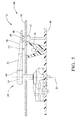
- Fig. 3 further illustrates non-limiting features of the assembly 12 by removing the applique (18 in Fig. 2 ) so the interaction between the pointer 24 and other objects can be more easily understood.
- the pointer 34 is operable to move about an axis 32 to point at indicia 26 ( Fig. 2 ) defined by the assembly 12.
- a key feature of the pointer 24 described herein is that the pointer 24 is configured or operable to vary a length 34 of the pointer 24 in response to a magnetic field 36 proximate to the pointer 24.
- the length 34 may be continuously variable between an extended length L1 and a retracted length L2.
- the pointer may include a fixed portion 40 and retractable portion 38.
- the fixed portion 40 refers to the idea that the radial length of the fixed portion 40 is not variable, and is not intended to imply that the pointer 24 rotational fixed, i.e. the pointer 24 is able to rotate about the axis 32.
- the fixed portion 40 may define a slot 42 that the retractable portion 38 can move into to vary the length 34 toward the retracted length L2.
- the assembly also includes a magnetic device 44 configured to cooperate with the pointer 24 to vary the length 34 of the pointer 24.
- the magnetic device 44 generally includes a part to generate the magnetic field 36, and a part that is acted upon by the magnetic field 36.
- the magnetic device 44 may include a permanent magnet or an electromagnet, which may be located on or attached to the pointer 24, or may be located on or attached to a circuit board 46 behind the applique (18 in Fig. 2 ). It is contemplated that there are many ways to use magnetic attraction/repulsion to vary the length of the pointer, so it is noted that the scope of the assembly 12 described herein is not limited to the examples presented herein.
- variable length pointer The advantages of a variable length pointer include, but are not limited to, being able to retract the pointer 24 so it does not collide with or contact another nearby pointer (not show), or so that the pointer 24 does not obstruct the viewing of a graphical indicator 28. Furthermore, the variable length may provide an additional means to attract the attention of the operator 14 or make the appearance of the assembly more pleasing by, for example, making the pointer 24 longer when a critical condition is being indicated such as the operating temperature of the vehicle's engine is too high, or the oil pressure of the vehicle's engine is too low.
- the magnetic device 44 includes a permanent magnet 48 attached to the pointer 24, for example the retractable portion 38 of the pointer. Accordingly, the assembly 12 is configured to provide or generate the magnetic field 36 to vary the length 34 of the pointer 24.
- the magnetic field 36 may be provided by an array of permanent magnets, hereafter referred to as the array 50, which may be mounted on the circuit board 46 at a location proximate to the area swept by the pointer 24 as the pointer rotates about the axis.
- the array 50 is arranged so the radial distance of each magnet in the array 50 from the axis 32 decreases as the angular orientation changes. Then, as the pointer 24 sweeps from the twelve o'clock position to the two o'clock position, the length 34 varies from the extended length L1 to the retracted length L2.
- the array 50 may include electromagnets instead of permanent magnets. Then if the electromagnets are not activated, the pointer 24 may selectively stay at the extended length L1 regardless of the angular orientation of the pointer 24, or if the electromagnets are activated the length 34 may vary in the same manner as would be the case for the array 50 being formed of permanent magnets. It is recognized that the pointer 24 may include a spring (not shown) or other means to urge the retractable portion 38 away of from the fixed portion 40 so that the pointer is at the extended length L1 when no electromagnet is activated.
- Figs. 4 and 5 illustrate another non-limiting example of the assembly where the magnetic device 44 includes an electromagnet 52 arranged proximate to the pointer 24.
- the electromagnet 52 is configured to provide the magnetic field 36 to vary the length 34 of the pointer 24.
- the high-beam indicator one of the graphical indicators 28 illustrated
- the electromagnet would not be activated and the pointer would remain at the extended length L1 if the pointer 24 swept over the high beam indicator.
- a controller 54 Fig. 1
- the electromagnet 52 is illustrated with the appearance generating the magnetic field at only one location proximate to the high beam indicator, it is contemplated that the electromagnet could be configured to generate a field that held the pointer 24 in at the retracted length L2 regardless of the angle of the pointer 24. That is, with reference to Fig. 4 , the pointer 24 could stay at the retracted length L2 or the extended length L1 regardless of the speed being indicated, and only dependent on the activation of the electromagnet 52.
- the pointer 24 may be equipped with a permanent magnet 48 attached to the retractable portion 38 of the pointer 24.
- the permanent magnet 48 cooperates with the electromagnet 52 to vary the length 34 of the pointer 24.
- the permanent magnet 48 may be replaced by a core 56 formed of ferromagnetic material attached to the pointer 24 that cooperates with the electromagnet 52 to vary the length 34 of the pointer 24.
- an iron core i.e. the core 56
- an instrument panel assembly (the assembly 12) with a variable length pointer (the pointer 24) is provided.
- the assembly 12 makes use of use magnetic attraction/repulsion to vary the length 34 of the pointer 24.
- Having a variable length pointer is advantageous as multiple pointers can be more closely arranged on the display surface of the assembly without risk of pointers colliding with one another, and the graphical indicators 28 can be located within the area of the display surface swept by the pointer 24 without the risk of having the pointer obstruct the operators ability to view the graphical indicators 28.
Landscapes
- Physics & Mathematics (AREA)
- General Physics & Mathematics (AREA)
- Engineering & Computer Science (AREA)
- Chemical & Material Sciences (AREA)
- Combustion & Propulsion (AREA)
- Transportation (AREA)
- Mechanical Engineering (AREA)
- Instrument Panels (AREA)
- Details Of Measuring Devices (AREA)
Abstract
Description
- This disclosure generally relates to an instrument panel assembly for displaying vehicle information, and more particularly relates to a variable length pointer that varies length in response to a magnetic field.
- As vehicles become more sophisticated, it is necessary to convey more information to an operator of a vehicle. For example, vehicle systems such as traction control, occupant protection (e.g. air-bags), anti-lock braking, cruise control, and forward and reward illumination are often configured to perform self-diagnostic tests. If a self-diagnostic test detects a problem with a system, a graphical indicator or telltale on a vehicle instrument panel may be illuminated to inform the operator of the problem. As the number of graphical indictors increases, but the area of the instrument panel display surface remains the same, instrument panel assemblies that employ mechanical pointers may have situations where the pointer undesirable obstructs the view of the graphical indicator. Also, the number of mechanical pointers that an instrument panel can include is limited by the area of the display that is swept by the mechanical pointers. If the swept areas overlap or intersect, there is a risk of adjacent mechanical pointers colliding. Furthermore, some of the display area of the assembly may not be fully utilized because of circular shape of the area swept by the pointer.
- Described herein is an instrument panel assembly that used a variable length pointer to overcome the problems described above. In general, the assembly makes use of magnetic attraction/repulsion to vary the length of the pointer.
- In accordance with one embodiment, an instrument panel assembly for displaying vehicle information is provided. The assembly includes a pointer and a magnetic device. The pointer is operable to move about an axis to point at indicia defined by the assembly. The pointer is also operable to vary a length of the pointer in response to a magnetic field proximate to the pointer. The magnetic is device configured to cooperate with the pointer to vary the length of the pointer.
- Further features and advantages will appear more clearly on a reading of the following detailed description of the preferred embodiment, which is given by way of non-limiting example only and with reference to the accompanying drawings.
- The present invention will now be described, by way of example with reference to the accompanying drawings, in which:
-
Fig. 1 is a perspective view of a vehicle interior equipped with an instrument panel assembly in accordance with one embodiment; -
Fig. 2 is an exploded perspective view of part of the assembly ofFig. 1 in accordance with one embodiment; -
Fig. 3 is an isometric view of part of the assembly ofFig. 1 in accordance with one embodiment; -
Fig. 4 is a front view of part of the assembly ofFig. 1 in accordance with one embodiment; and -
Fig. 5 is a side view of part of the assembly ofFig. 1 in accordance with one embodiment. -
Fig. 1 illustrates a non-limiting example of avehicle 10 equipped with an instrument panel assembly, hereafter referred to as theassembly 12, installed into adashboard 16 of thevehicle 10. In general, theassembly 12 displays vehicle information to anoperator 14 of thevehicle 10 such as vehicle speed, engine coolant temperature, and the like. -
Fig. 2 illustrates a non-limiting example of theassembly 12 as it might appear when not installed into thedashboard 16 of thevehicle 10. In general, theassembly 12 includes anapplique 18. In this example theapplique 18 spans most of the viewing area of theassembly 12. Theassembly 12 also typically includes abase 20 and alens 22 for supporting various parts that make up theassembly 12 and protecting thepointers 24 and the applique 18 from contact damage and contaminants. Theapplique 18 typically includesindicia 26 that thepointers 24 point at to convey information to theoperator 14. The applique may also one or more includegraphical indicators 28 configured to become visibly apparent to theoperator 14 when suitably backlit. Non-limiting examples of thegraphical indicators 28 include a high-beam indicator and a parking brake indicator, as will be recognized by those in the art. - Backlighting of the
applique 18 and selective illumination of thegraphical indicators 28 is generally provided by a number of light sources, for example an indicator light source 30 (Fig. 5 ). These light sources are preferably light emitting diodes (LEDs), as LEDs are reliable, economical, and typically generate less heat than other types of light sources such as incandescent bulbs. However, theassembly 12 described herein is not limited to using LEDs as light sources. -
Fig. 3 further illustrates non-limiting features of theassembly 12 by removing the applique (18 inFig. 2 ) so the interaction between thepointer 24 and other objects can be more easily understood. In general, thepointer 34 is operable to move about anaxis 32 to point at indicia 26 (Fig. 2 ) defined by theassembly 12. A key feature of thepointer 24 described herein is that thepointer 24 is configured or operable to vary alength 34 of thepointer 24 in response to amagnetic field 36 proximate to thepointer 24. Thelength 34 may be continuously variable between an extended length L1 and a retracted length L2. To vary thelength 34 of thepointer 24, the pointer may include a fixedportion 40 andretractable portion 38. As used herein, thefixed portion 40 refers to the idea that the radial length of thefixed portion 40 is not variable, and is not intended to imply that thepointer 24 rotational fixed, i.e. thepointer 24 is able to rotate about theaxis 32. Thefixed portion 40 may define aslot 42 that theretractable portion 38 can move into to vary thelength 34 toward the retracted length L2. - The assembly also includes a
magnetic device 44 configured to cooperate with thepointer 24 to vary thelength 34 of thepointer 24. As used herein, themagnetic device 44 generally includes a part to generate themagnetic field 36, and a part that is acted upon by themagnetic field 36. As will be explained in more detail below, themagnetic device 44 may include a permanent magnet or an electromagnet, which may be located on or attached to thepointer 24, or may be located on or attached to acircuit board 46 behind the applique (18 inFig. 2 ). It is contemplated that there are many ways to use magnetic attraction/repulsion to vary the length of the pointer, so it is noted that the scope of theassembly 12 described herein is not limited to the examples presented herein. - The advantages of a variable length pointer include, but are not limited to, being able to retract the
pointer 24 so it does not collide with or contact another nearby pointer (not show), or so that thepointer 24 does not obstruct the viewing of agraphical indicator 28. Furthermore, the variable length may provide an additional means to attract the attention of theoperator 14 or make the appearance of the assembly more pleasing by, for example, making thepointer 24 longer when a critical condition is being indicated such as the operating temperature of the vehicle's engine is too high, or the oil pressure of the vehicle's engine is too low. - In one example, the
magnetic device 44 includes apermanent magnet 48 attached to thepointer 24, for example theretractable portion 38 of the pointer. Accordingly, theassembly 12 is configured to provide or generate themagnetic field 36 to vary thelength 34 of thepointer 24. By way of further example, themagnetic field 36 may be provided by an array of permanent magnets, hereafter referred to as thearray 50, which may be mounted on thecircuit board 46 at a location proximate to the area swept by thepointer 24 as the pointer rotates about the axis. In this example thearray 50 is arranged so the radial distance of each magnet in thearray 50 from theaxis 32 decreases as the angular orientation changes. Then, as thepointer 24 sweeps from the twelve o'clock position to the two o'clock position, thelength 34 varies from the extended length L1 to the retracted length L2. - Alternatively, the
array 50 may include electromagnets instead of permanent magnets. Then if the electromagnets are not activated, thepointer 24 may selectively stay at the extended length L1 regardless of the angular orientation of thepointer 24, or if the electromagnets are activated thelength 34 may vary in the same manner as would be the case for thearray 50 being formed of permanent magnets. It is recognized that thepointer 24 may include a spring (not shown) or other means to urge theretractable portion 38 away of from thefixed portion 40 so that the pointer is at the extended length L1 when no electromagnet is activated. -
Figs. 4 and5 illustrate another non-limiting example of the assembly where themagnetic device 44 includes anelectromagnet 52 arranged proximate to thepointer 24. Theelectromagnet 52 is configured to provide themagnetic field 36 to vary thelength 34 of thepointer 24. By way of further example, if the high-beam indicator (one of thegraphical indicators 28 illustrated) is not illuminated, then the electromagnet would not be activated and the pointer would remain at the extended length L1 if thepointer 24 swept over the high beam indicator. However, if the high-beam indicator was illuminated, a controller 54 (Fig. 1 ) may operate theelectromagnet 52 so that thepointer 24 was urged by themagnetic field 36 to the retracted length L2. While theelectromagnet 52 is illustrated with the appearance generating the magnetic field at only one location proximate to the high beam indicator, it is contemplated that the electromagnet could be configured to generate a field that held thepointer 24 in at the retracted length L2 regardless of the angle of thepointer 24. That is, with reference toFig. 4 , thepointer 24 could stay at the retracted length L2 or the extended length L1 regardless of the speed being indicated, and only dependent on the activation of theelectromagnet 52. - The
pointer 24 may be equipped with apermanent magnet 48 attached to theretractable portion 38 of thepointer 24. As mentioned before, thepermanent magnet 48 cooperates with theelectromagnet 52 to vary thelength 34 of thepointer 24. Alternatively, thepermanent magnet 48 may be replaced by a core 56 formed of ferromagnetic material attached to thepointer 24 that cooperates with theelectromagnet 52 to vary thelength 34 of thepointer 24. By installing an iron core (i.e. the core 56) instead of thepermanent magnet 48 onto the retractable portion, the movement of theretractable portion 38 relative to themagnetic field 36 is comparable to that of an iron core in a solenoid. - Accordingly, an instrument panel assembly (the assembly 12) with a variable length pointer (the pointer 24) is provided. The
assembly 12 makes use of use magnetic attraction/repulsion to vary thelength 34 of thepointer 24. Having a variable length pointer is advantageous as multiple pointers can be more closely arranged on the display surface of the assembly without risk of pointers colliding with one another, and thegraphical indicators 28 can be located within the area of the display surface swept by thepointer 24 without the risk of having the pointer obstruct the operators ability to view thegraphical indicators 28. - While this invention has been described in terms of the preferred embodiments thereof, it is not intended to be so limited, but rather only to the extent set forth in the claims that follow.
Claims (7)
- An instrument panel assembly (12) for displaying vehicle (10) information, said assembly (12) comprising:a pointer (24) operable to move about an axis (32) to point at indicia (26) defined by the assembly (12), wherein the pointer (24) is operable to vary a length (34) of the pointer (24) in response to a magnetic field (36) proximate to the pointer (24); anda magnetic device (44) configured to cooperate with the pointer (24) to vary the length (34) of the pointer (24).
- The assembly (12) in accordance with claim 1, wherein the magnetic device (44) includes a permanent magnet (48) attached to the pointer (24), and the assembly (12) is configured to provide a magnetic field (36) to vary the length (34) of the pointer (24).
- The assembly (12) in accordance with claim 2, wherein the magnetic field (36) is provided by an array (50) of permanent magnets arranged proximate to the pointer (24).
- The assembly (12) in accordance with claim 2, wherein the magnetic field (36) is provided by an electromagnet (52) arranged proximate to the pointer (24).
- The assembly (12) in accordance with claim 1, wherein the magnetic device (44) includes an electromagnet (52) arranged proximate to the pointer (24) and configured to provide a magnetic field (36) to vary the length (34) of the pointer (24).
- The assembly (12) in accordance with claim 5, wherein the assembly (12) includes a permanent magnet (48) attached to the pointer (24) that cooperates with the electromagnet (52) to vary the length (34) of the pointer (24).
- The assembly (12) in accordance with claim 5, wherein the assembly (12) includes a core (56) formed of ferromagnetic material attached to the pointer (24) that cooperates with the electromagnet (52) to vary the length (34) of the pointer (24).
Applications Claiming Priority (1)
| Application Number | Priority Date | Filing Date | Title |
|---|---|---|---|
| US14/486,176 US9404774B2 (en) | 2014-09-15 | 2014-09-15 | Instrument panel assembly with variable length pointer |
Publications (3)
| Publication Number | Publication Date |
|---|---|
| EP2995493A2 true EP2995493A2 (en) | 2016-03-16 |
| EP2995493A3 EP2995493A3 (en) | 2016-11-30 |
| EP2995493B1 EP2995493B1 (en) | 2018-01-31 |
Family
ID=54007567
Family Applications (1)
| Application Number | Title | Priority Date | Filing Date |
|---|---|---|---|
| EP15182154.3A Active EP2995493B1 (en) | 2014-09-15 | 2015-08-24 | Instrument panel assembly with variable length pointer |
Country Status (3)
| Country | Link |
|---|---|
| US (1) | US9404774B2 (en) |
| EP (1) | EP2995493B1 (en) |
| CN (1) | CN106183811B (en) |
Families Citing this family (1)
| Publication number | Priority date | Publication date | Assignee | Title |
|---|---|---|---|---|
| JP7706822B2 (en) * | 2022-03-07 | 2025-07-14 | パナソニックオートモーティブシステムズ株式会社 | display device |
Family Cites Families (13)
| Publication number | Priority date | Publication date | Assignee | Title |
|---|---|---|---|---|
| GB905200A (en) * | 1960-02-08 | 1962-09-05 | Smith & Sons Ltd S | Improvements in indicating instruments |
| JPH0519918U (en) * | 1991-08-26 | 1993-03-12 | 矢崎総業株式会社 | Analog display |
| JP3389727B2 (en) * | 1995-03-15 | 2003-03-24 | 株式会社デンソー | Indicating instrument |
| DE10043950A1 (en) * | 2000-02-23 | 2002-03-21 | Mannesmann Vdo Ag | Display device with a pointer |
| DE10041474A1 (en) * | 2000-08-24 | 2002-03-07 | Mannesmann Vdo Ag | Display device with a pointer |
| US6624608B2 (en) * | 2001-02-23 | 2003-09-23 | Denso Corporation | Indicating instrument for a vehicle |
| DE102005015178A1 (en) * | 2005-03-31 | 2006-10-05 | Siemens Ag | Display for displaying engine speed of motor vehicle, has pointer rotatable around axis of rotation and represents physical value by rotation in interaction with scale, where pointer/pointer background proportionally displays another value |
| FR2902885B1 (en) * | 2006-06-22 | 2008-12-05 | Peugeot Citroen Automobiles Sa | DEVICE FOR INDICATING A NEEDLE SIZE, SUCH AS A TURN COUNTER FOR A VEHICLE. |
| JP5354477B2 (en) * | 2009-07-16 | 2013-11-27 | 日本精機株式会社 | Indicating instrument |
| FR2960637B1 (en) * | 2010-05-26 | 2013-04-12 | Moving Magnet Tech | COMPLEX PLAN MOVEMENT EDGE PANEL INDICATING DEVICE |
| CN102347085B (en) * | 2010-07-27 | 2013-12-04 | 比亚迪股份有限公司 | Pointer used for instrument, instrument containing the pointer, and manufacture method of pointer |
| WO2012153395A1 (en) * | 2011-05-10 | 2012-11-15 | トヨタ自動車株式会社 | Vehicle display device |
| DE102012014206B4 (en) * | 2012-07-17 | 2014-04-03 | Audi Ag | Indicating instrument for a motor vehicle |
-
2014
- 2014-09-15 US US14/486,176 patent/US9404774B2/en active Active
-
2015
- 2015-07-16 CN CN201510418788.2A patent/CN106183811B/en active Active
- 2015-08-24 EP EP15182154.3A patent/EP2995493B1/en active Active
Non-Patent Citations (1)
| Title |
|---|
| None |
Also Published As
| Publication number | Publication date |
|---|---|
| CN106183811B (en) | 2019-06-04 |
| EP2995493A3 (en) | 2016-11-30 |
| US9404774B2 (en) | 2016-08-02 |
| EP2995493B1 (en) | 2018-01-31 |
| US20160076922A1 (en) | 2016-03-17 |
| CN106183811A (en) | 2016-12-07 |
Similar Documents
| Publication | Publication Date | Title |
|---|---|---|
| EP2653346A1 (en) | Vehicle safety illumination arrangement and method | |
| JP6512782B2 (en) | Information presentation device | |
| EP1799486B1 (en) | Instrument cluster with translucent or transparent sheet | |
| EP2348291B1 (en) | Pointer structure of an instrument cluster | |
| US20030090886A1 (en) | Thin instrument cluster | |
| US10266054B2 (en) | Vehicle display device | |
| JP4939435B2 (en) | Instrument cluster | |
| EP2995493B1 (en) | Instrument panel assembly with variable length pointer | |
| KR101851433B1 (en) | Increasing pointer brightness to indicate warning level | |
| KR101771203B1 (en) | Safety tripod for vehicle using the laser | |
| US20150306958A1 (en) | Instrument cluster including telltale illumination | |
| US9061591B2 (en) | Instrument panel pointer with transparent section | |
| US9568343B2 (en) | Dash line pointer | |
| KR101734258B1 (en) | A danger indicator of vehicle | |
| KR101561399B1 (en) | Display device for a vehicle | |
| EP2679965A2 (en) | Needle indicator oriented by periphery electromagnets | |
| US7030774B2 (en) | Floating visible indicator for an instrument cluster | |
| KR101784732B1 (en) | Thin gauge with self-emitting display for hidden pointer | |
| JP2010100260A (en) | Vehicle state display | |
| CN105857080A (en) | Vehicle instrument panel with pointer presence detection | |
| US20170115140A1 (en) | Indicating device with see-through configuration and pointer for the same | |
| JP4175321B2 (en) | Pointer instrument | |
| JP6400185B2 (en) | Vehicle display device | |
| JP2007004986A (en) | Push-button switch | |
| JP2011075764A (en) | Display device |
Legal Events
| Date | Code | Title | Description |
|---|---|---|---|
| PUAI | Public reference made under article 153(3) epc to a published international application that has entered the european phase |
Free format text: ORIGINAL CODE: 0009012 |
|
| AK | Designated contracting states |
Kind code of ref document: A2 Designated state(s): AL AT BE BG CH CY CZ DE DK EE ES FI FR GB GR HR HU IE IS IT LI LT LU LV MC MK MT NL NO PL PT RO RS SE SI SK SM TR |
|
| AX | Request for extension of the european patent |
Extension state: BA ME |
|
| PUAL | Search report despatched |
Free format text: ORIGINAL CODE: 0009013 |
|
| AK | Designated contracting states |
Kind code of ref document: A3 Designated state(s): AL AT BE BG CH CY CZ DE DK EE ES FI FR GB GR HR HU IE IS IT LI LT LU LV MC MK MT NL NO PL PT RO RS SE SI SK SM TR |
|
| AX | Request for extension of the european patent |
Extension state: BA ME |
|
| RIC1 | Information provided on ipc code assigned before grant |
Ipc: B60K 37/02 20060101AFI20161026BHEP Ipc: G01D 13/26 20060101ALI20161026BHEP Ipc: G01D 13/22 20060101ALI20161026BHEP |
|
| 17P | Request for examination filed |
Effective date: 20170530 |
|
| RBV | Designated contracting states (corrected) |
Designated state(s): AL AT BE BG CH CY CZ DE DK EE ES FI FR GB GR HR HU IE IS IT LI LT LU LV MC MK MT NL NO PL PT RO RS SE SI SK SM TR |
|
| GRAP | Despatch of communication of intention to grant a patent |
Free format text: ORIGINAL CODE: EPIDOSNIGR1 |
|
| INTG | Intention to grant announced |
Effective date: 20170830 |
|
| GRAS | Grant fee paid |
Free format text: ORIGINAL CODE: EPIDOSNIGR3 |
|
| GRAA | (expected) grant |
Free format text: ORIGINAL CODE: 0009210 |
|
| AK | Designated contracting states |
Kind code of ref document: B1 Designated state(s): AL AT BE BG CH CY CZ DE DK EE ES FI FR GB GR HR HU IE IS IT LI LT LU LV MC MK MT NL NO PL PT RO RS SE SI SK SM TR |
|
| REG | Reference to a national code |
Ref country code: GB Ref legal event code: FG4D Ref country code: CH Ref legal event code: EP |
|
| REG | Reference to a national code |
Ref country code: AT Ref legal event code: REF Ref document number: 967023 Country of ref document: AT Kind code of ref document: T Effective date: 20180215 |
|
| REG | Reference to a national code |
Ref country code: IE Ref legal event code: FG4D |
|
| REG | Reference to a national code |
Ref country code: DE Ref legal event code: R096 Ref document number: 602015007715 Country of ref document: DE |
|
| REG | Reference to a national code |
Ref country code: NL Ref legal event code: MP Effective date: 20180131 |
|
| REG | Reference to a national code |
Ref country code: LT Ref legal event code: MG4D |
|
| REG | Reference to a national code |
Ref country code: AT Ref legal event code: MK05 Ref document number: 967023 Country of ref document: AT Kind code of ref document: T Effective date: 20180131 |
|
| PG25 | Lapsed in a contracting state [announced via postgrant information from national office to epo] |
Ref country code: LT Free format text: LAPSE BECAUSE OF FAILURE TO SUBMIT A TRANSLATION OF THE DESCRIPTION OR TO PAY THE FEE WITHIN THE PRESCRIBED TIME-LIMIT Effective date: 20180131 Ref country code: HR Free format text: LAPSE BECAUSE OF FAILURE TO SUBMIT A TRANSLATION OF THE DESCRIPTION OR TO PAY THE FEE WITHIN THE PRESCRIBED TIME-LIMIT Effective date: 20180131 Ref country code: ES Free format text: LAPSE BECAUSE OF FAILURE TO SUBMIT A TRANSLATION OF THE DESCRIPTION OR TO PAY THE FEE WITHIN THE PRESCRIBED TIME-LIMIT Effective date: 20180131 Ref country code: NL Free format text: LAPSE BECAUSE OF FAILURE TO SUBMIT A TRANSLATION OF THE DESCRIPTION OR TO PAY THE FEE WITHIN THE PRESCRIBED TIME-LIMIT Effective date: 20180131 Ref country code: NO Free format text: LAPSE BECAUSE OF FAILURE TO SUBMIT A TRANSLATION OF THE DESCRIPTION OR TO PAY THE FEE WITHIN THE PRESCRIBED TIME-LIMIT Effective date: 20180430 Ref country code: FI Free format text: LAPSE BECAUSE OF FAILURE TO SUBMIT A TRANSLATION OF THE DESCRIPTION OR TO PAY THE FEE WITHIN THE PRESCRIBED TIME-LIMIT Effective date: 20180131 |
|
| REG | Reference to a national code |
Ref country code: FR Ref legal event code: PLFP Year of fee payment: 4 |
|
| PG25 | Lapsed in a contracting state [announced via postgrant information from national office to epo] |
Ref country code: AT Free format text: LAPSE BECAUSE OF FAILURE TO SUBMIT A TRANSLATION OF THE DESCRIPTION OR TO PAY THE FEE WITHIN THE PRESCRIBED TIME-LIMIT Effective date: 20180131 Ref country code: RS Free format text: LAPSE BECAUSE OF FAILURE TO SUBMIT A TRANSLATION OF THE DESCRIPTION OR TO PAY THE FEE WITHIN THE PRESCRIBED TIME-LIMIT Effective date: 20180131 Ref country code: SE Free format text: LAPSE BECAUSE OF FAILURE TO SUBMIT A TRANSLATION OF THE DESCRIPTION OR TO PAY THE FEE WITHIN THE PRESCRIBED TIME-LIMIT Effective date: 20180131 Ref country code: LV Free format text: LAPSE BECAUSE OF FAILURE TO SUBMIT A TRANSLATION OF THE DESCRIPTION OR TO PAY THE FEE WITHIN THE PRESCRIBED TIME-LIMIT Effective date: 20180131 Ref country code: PL Free format text: LAPSE BECAUSE OF FAILURE TO SUBMIT A TRANSLATION OF THE DESCRIPTION OR TO PAY THE FEE WITHIN THE PRESCRIBED TIME-LIMIT Effective date: 20180131 Ref country code: GR Free format text: LAPSE BECAUSE OF FAILURE TO SUBMIT A TRANSLATION OF THE DESCRIPTION OR TO PAY THE FEE WITHIN THE PRESCRIBED TIME-LIMIT Effective date: 20180501 Ref country code: IS Free format text: LAPSE BECAUSE OF FAILURE TO SUBMIT A TRANSLATION OF THE DESCRIPTION OR TO PAY THE FEE WITHIN THE PRESCRIBED TIME-LIMIT Effective date: 20180531 Ref country code: BG Free format text: LAPSE BECAUSE OF FAILURE TO SUBMIT A TRANSLATION OF THE DESCRIPTION OR TO PAY THE FEE WITHIN THE PRESCRIBED TIME-LIMIT Effective date: 20180430 |
|
| PG25 | Lapsed in a contracting state [announced via postgrant information from national office to epo] |
Ref country code: AL Free format text: LAPSE BECAUSE OF FAILURE TO SUBMIT A TRANSLATION OF THE DESCRIPTION OR TO PAY THE FEE WITHIN THE PRESCRIBED TIME-LIMIT Effective date: 20180131 Ref country code: RO Free format text: LAPSE BECAUSE OF FAILURE TO SUBMIT A TRANSLATION OF THE DESCRIPTION OR TO PAY THE FEE WITHIN THE PRESCRIBED TIME-LIMIT Effective date: 20180131 Ref country code: EE Free format text: LAPSE BECAUSE OF FAILURE TO SUBMIT A TRANSLATION OF THE DESCRIPTION OR TO PAY THE FEE WITHIN THE PRESCRIBED TIME-LIMIT Effective date: 20180131 Ref country code: IT Free format text: LAPSE BECAUSE OF FAILURE TO SUBMIT A TRANSLATION OF THE DESCRIPTION OR TO PAY THE FEE WITHIN THE PRESCRIBED TIME-LIMIT Effective date: 20180131 |
|
| REG | Reference to a national code |
Ref country code: DE Ref legal event code: R097 Ref document number: 602015007715 Country of ref document: DE |
|
| PG25 | Lapsed in a contracting state [announced via postgrant information from national office to epo] |
Ref country code: SK Free format text: LAPSE BECAUSE OF FAILURE TO SUBMIT A TRANSLATION OF THE DESCRIPTION OR TO PAY THE FEE WITHIN THE PRESCRIBED TIME-LIMIT Effective date: 20180131 Ref country code: CZ Free format text: LAPSE BECAUSE OF FAILURE TO SUBMIT A TRANSLATION OF THE DESCRIPTION OR TO PAY THE FEE WITHIN THE PRESCRIBED TIME-LIMIT Effective date: 20180131 Ref country code: DK Free format text: LAPSE BECAUSE OF FAILURE TO SUBMIT A TRANSLATION OF THE DESCRIPTION OR TO PAY THE FEE WITHIN THE PRESCRIBED TIME-LIMIT Effective date: 20180131 Ref country code: SM Free format text: LAPSE BECAUSE OF FAILURE TO SUBMIT A TRANSLATION OF THE DESCRIPTION OR TO PAY THE FEE WITHIN THE PRESCRIBED TIME-LIMIT Effective date: 20180131 |
|
| REG | Reference to a national code |
Ref country code: DE Ref legal event code: R081 Ref document number: 602015007715 Country of ref document: DE Owner name: APTIV TECHNOLOGIES LIMITED, BB Free format text: FORMER OWNER: DELPHI TECHNOLOGIES, INC., TROY, MICH., US |
|
| PLBE | No opposition filed within time limit |
Free format text: ORIGINAL CODE: 0009261 |
|
| STAA | Information on the status of an ep patent application or granted ep patent |
Free format text: STATUS: NO OPPOSITION FILED WITHIN TIME LIMIT |
|
| 26N | No opposition filed |
Effective date: 20181102 |
|
| REG | Reference to a national code |
Ref country code: GB Ref legal event code: 732E Free format text: REGISTERED BETWEEN 20190117 AND 20190123 |
|
| REG | Reference to a national code |
Ref country code: GB Ref legal event code: 732E Free format text: REGISTERED BETWEEN 20190124 AND 20190130 |
|
| PG25 | Lapsed in a contracting state [announced via postgrant information from national office to epo] |
Ref country code: SI Free format text: LAPSE BECAUSE OF FAILURE TO SUBMIT A TRANSLATION OF THE DESCRIPTION OR TO PAY THE FEE WITHIN THE PRESCRIBED TIME-LIMIT Effective date: 20180131 |
|
| PG25 | Lapsed in a contracting state [announced via postgrant information from national office to epo] |
Ref country code: MC Free format text: LAPSE BECAUSE OF FAILURE TO SUBMIT A TRANSLATION OF THE DESCRIPTION OR TO PAY THE FEE WITHIN THE PRESCRIBED TIME-LIMIT Effective date: 20180131 |
|
| REG | Reference to a national code |
Ref country code: CH Ref legal event code: PL |
|
| PG25 | Lapsed in a contracting state [announced via postgrant information from national office to epo] |
Ref country code: LI Free format text: LAPSE BECAUSE OF NON-PAYMENT OF DUE FEES Effective date: 20180831 Ref country code: LU Free format text: LAPSE BECAUSE OF NON-PAYMENT OF DUE FEES Effective date: 20180824 Ref country code: CH Free format text: LAPSE BECAUSE OF NON-PAYMENT OF DUE FEES Effective date: 20180831 |
|
| REG | Reference to a national code |
Ref country code: BE Ref legal event code: MM Effective date: 20180831 |
|
| PG25 | Lapsed in a contracting state [announced via postgrant information from national office to epo] |
Ref country code: BE Free format text: LAPSE BECAUSE OF NON-PAYMENT OF DUE FEES Effective date: 20180831 |
|
| PG25 | Lapsed in a contracting state [announced via postgrant information from national office to epo] |
Ref country code: MT Free format text: LAPSE BECAUSE OF NON-PAYMENT OF DUE FEES Effective date: 20180824 |
|
| PG25 | Lapsed in a contracting state [announced via postgrant information from national office to epo] |
Ref country code: TR Free format text: LAPSE BECAUSE OF FAILURE TO SUBMIT A TRANSLATION OF THE DESCRIPTION OR TO PAY THE FEE WITHIN THE PRESCRIBED TIME-LIMIT Effective date: 20180131 |
|
| PG25 | Lapsed in a contracting state [announced via postgrant information from national office to epo] |
Ref country code: PT Free format text: LAPSE BECAUSE OF FAILURE TO SUBMIT A TRANSLATION OF THE DESCRIPTION OR TO PAY THE FEE WITHIN THE PRESCRIBED TIME-LIMIT Effective date: 20180131 |
|
| PG25 | Lapsed in a contracting state [announced via postgrant information from national office to epo] |
Ref country code: HU Free format text: LAPSE BECAUSE OF FAILURE TO SUBMIT A TRANSLATION OF THE DESCRIPTION OR TO PAY THE FEE WITHIN THE PRESCRIBED TIME-LIMIT; INVALID AB INITIO Effective date: 20150824 Ref country code: CY Free format text: LAPSE BECAUSE OF FAILURE TO SUBMIT A TRANSLATION OF THE DESCRIPTION OR TO PAY THE FEE WITHIN THE PRESCRIBED TIME-LIMIT Effective date: 20180131 Ref country code: IE Free format text: LAPSE BECAUSE OF NON-PAYMENT OF DUE FEES Effective date: 20180824 Ref country code: MK Free format text: LAPSE BECAUSE OF NON-PAYMENT OF DUE FEES Effective date: 20180131 |
|
| P01 | Opt-out of the competence of the unified patent court (upc) registered |
Effective date: 20230425 |
|
| REG | Reference to a national code |
Ref country code: DE Ref legal event code: R079 Ref document number: 602015007715 Country of ref document: DE Free format text: PREVIOUS MAIN CLASS: B60K0037020000 Ipc: B60K0035600000 |
|
| REG | Reference to a national code |
Ref country code: DE Ref legal event code: R081 Ref document number: 602015007715 Country of ref document: DE Owner name: APTIV TECHNOLOGIES AG, CH Free format text: FORMER OWNER: APTIV TECHNOLOGIES LIMITED, ST. MICHAEL, BB |
|
| PGFP | Annual fee paid to national office [announced via postgrant information from national office to epo] |
Ref country code: DE Payment date: 20250722 Year of fee payment: 11 |
|
| PGFP | Annual fee paid to national office [announced via postgrant information from national office to epo] |
Ref country code: GB Payment date: 20250813 Year of fee payment: 11 |
|
| PGFP | Annual fee paid to national office [announced via postgrant information from national office to epo] |
Ref country code: FR Payment date: 20250812 Year of fee payment: 11 |