JP4939435B2 - Instrument cluster - Google Patents
Instrument cluster Download PDFInfo
- Publication number
- JP4939435B2 JP4939435B2 JP2007550490A JP2007550490A JP4939435B2 JP 4939435 B2 JP4939435 B2 JP 4939435B2 JP 2007550490 A JP2007550490 A JP 2007550490A JP 2007550490 A JP2007550490 A JP 2007550490A JP 4939435 B2 JP4939435 B2 JP 4939435B2
- Authority
- JP
- Japan
- Prior art keywords
- light
- instrument cluster
- vehicle
- partially translucent
- instrument
- Prior art date
- Legal status (The legal status is an assumption and is not a legal conclusion. Google has not performed a legal analysis and makes no representation as to the accuracy of the status listed.)
- Expired - Fee Related
Links
- 238000005286 illumination Methods 0.000 claims abstract description 18
- 239000000463 material Substances 0.000 claims description 23
- 238000000576 coating method Methods 0.000 claims description 7
- 239000011248 coating agent Substances 0.000 claims description 6
- 239000002184 metal Substances 0.000 claims 1
- 238000000034 method Methods 0.000 description 15
- 230000000007 visual effect Effects 0.000 description 9
- 239000004033 plastic Substances 0.000 description 6
- 229920003023 plastic Polymers 0.000 description 6
- 239000000446 fuel Substances 0.000 description 5
- 239000010705 motor oil Substances 0.000 description 5
- 239000003086 colorant Substances 0.000 description 3
- 230000008878 coupling Effects 0.000 description 3
- 238000010168 coupling process Methods 0.000 description 3
- 238000005859 coupling reaction Methods 0.000 description 3
- 238000007667 floating Methods 0.000 description 3
- 239000011888 foil Substances 0.000 description 3
- 238000012986 modification Methods 0.000 description 3
- 230000004048 modification Effects 0.000 description 3
- 230000008901 benefit Effects 0.000 description 2
- 238000010586 diagram Methods 0.000 description 2
- 230000000694 effects Effects 0.000 description 2
- 238000004049 embossing Methods 0.000 description 2
- 238000005530 etching Methods 0.000 description 2
- 238000007373 indentation Methods 0.000 description 2
- 238000000465 moulding Methods 0.000 description 2
- 238000012876 topography Methods 0.000 description 2
- XLYOFNOQVPJJNP-UHFFFAOYSA-N water Substances O XLYOFNOQVPJJNP-UHFFFAOYSA-N 0.000 description 2
- NIXOWILDQLNWCW-UHFFFAOYSA-N acrylic acid group Chemical group C(C=C)(=O)O NIXOWILDQLNWCW-UHFFFAOYSA-N 0.000 description 1
- 239000000853 adhesive Substances 0.000 description 1
- 230000001070 adhesive effect Effects 0.000 description 1
- 238000004378 air conditioning Methods 0.000 description 1
- 230000000712 assembly Effects 0.000 description 1
- 238000000429 assembly Methods 0.000 description 1
- 238000004140 cleaning Methods 0.000 description 1
- 239000013078 crystal Substances 0.000 description 1
- 238000002050 diffraction method Methods 0.000 description 1
- 239000000295 fuel oil Substances 0.000 description 1
- 239000011521 glass Substances 0.000 description 1
- 125000001475 halogen functional group Chemical group 0.000 description 1
- 238000010329 laser etching Methods 0.000 description 1
- 239000007769 metal material Substances 0.000 description 1
- 229920000642 polymer Polymers 0.000 description 1
- 230000008569 process Effects 0.000 description 1
- 230000004044 response Effects 0.000 description 1
- 238000006467 substitution reaction Methods 0.000 description 1
- 238000003466 welding Methods 0.000 description 1
Images


Classifications
-
- B60K35/60—
-
- B60K2360/33—
Abstract
Description
〔関連出願の相互参照〕
本願は、2005年1月7日に出願された「Instrument Cluster」と題する米国仮出願第60/642239号の利点を、パリ条約第4条、および特許協力条約の規則4の下で主張するものであり、その米国仮出願第60/642239号は、本発明の譲受人に譲渡されており、その全てが本明細書に引用して援用される。
[Cross-reference of related applications]
This application claims the benefit of US Provisional Application No. 60/642239 entitled “Instrument Cluster” filed Jan. 7, 2005 under Article 4 of the Paris Convention and Rule 4 of the Patent Cooperation Treaty. No. 60/642239, which is assigned to the assignee of the present invention, which is hereby incorporated by reference in its entirety.
本発明は、一般に自動車のディスプレイ装置の分野に関し、特に車両用のインストルメントクラスタおよびパネルに関する。 The present invention relates generally to the field of automotive display devices, and more particularly to instrument clusters and panels for vehicles.
多くの車両は、様々な種類の情報を表示するインストルメントクラスタを備えている。この表示される情報は、スピードメーター、タコメーター、燃料油面計などの計測器からの情報を含んでもよい。また、この情報はシートベルトインジケータ、燃料残量低下警告、エンジンチェック警告、エンジン温度警告、アンチロックブレーキインジケータ、トラクションコントロールインジケータ、タイヤ空気圧警告、および/または他のインジケータからの情報を含んでいてもよい。この情報は、ターンシグナルインジケータをさらに含んでもよい。 Many vehicles have an instrument cluster that displays various types of information. This displayed information may include information from measuring instruments such as a speedometer, a tachometer, and a fuel oil level gauge. This information may also include information from seat belt indicators, low fuel warnings, engine check warnings, engine temperature warnings, antilock brake indicators, traction control indicators, tire pressure warnings, and / or other indicators. Good. This information may further include a turn signal indicator.
多くのインストルメントパネルおよびインストルメントクラスタは、昼夜の表示に対応して設計されている。したがって、インストルメントクラスタは、しばしば様々な種類の点灯システムを利用して、可読情報を昼夜供給するように設計されている。インストルメントパネルおよびインストルメントクラスタに利用されている既知の点灯システムは多くあるにもかかわらず、最も知られているシステムは通常ある種の審美的に心地よい特色および特徴をもたらすものではない。例えば、そのような既知のシステムは、車両の乗員の視点から見てベゼルが浮いているという錯覚が生じるように所定の距離だけ分離して照明するインストルメントクラスタおよびインストルメントパネルを備えていない。加えて、そのような既知のシステムは、背後の光源によって照明されない限り車両の乗員が依然として実質的に検出できない目盛マークまたは他のしるしを有するインストルメントクラスタを提供していない。 Many instrument panels and instrument clusters are designed for day and night displays. Therefore, instrument clusters are designed to provide readable information day and night, often using various types of lighting systems. Despite the many known lighting systems utilized for instrument panels and instrument clusters, the most known systems usually do not provide some aesthetically pleasing features and characteristics. For example, such a known system does not include an instrument cluster and an instrument panel that are separated and illuminated by a predetermined distance so as to create the illusion that the bezel is floating from the viewpoint of the vehicle occupant. In addition, such known systems do not provide instrument clusters having tick marks or other indicia that are still substantially undetectable by a vehicle occupant unless illuminated by a light source behind.
したがって、インストルメントクラスタおよびインストルメントパネルを所定の距離だけ分離でき、また、車両の乗員の視点から見てベゼルが浮いているという錯覚が生じるように照明することができるシステムおよび方法を提供すると有利になるであろう。「ふちなし(browless)」の外観を有するインストルメントクラスタを提供すると、さらに有利になるであろう。背後の光源によって照明されない限り車両の乗員には依然として実質的に検出できない3次元(3D)の目盛マークまたは他のしるしをインストルメントクラスタに具備することを可能にするシステムおよび方法を提供すると、さらに有利になるであろう。これらまたは他の有利な特徴の1つ以上をもたらすシステムおよび方法を提供すると望ましいであろう。 Thus, it would be advantageous to provide a system and method that can illuminate the instrument cluster and instrument panel by a predetermined distance and that can be illuminated to create the illusion that the bezel is floating from the perspective of the vehicle occupant. It will be. It would be further advantageous to provide an instrument cluster having a “browless” appearance. Providing a system and method that allows an instrument cluster to be provided with a three-dimensional (3D) scale mark or other indicia that is still substantially undetectable to a vehicle occupant unless illuminated by a light source behind Will be advantageous. It would be desirable to provide systems and methods that provide one or more of these or other advantageous features.
本明細書における教示は、それらの教示が上述の問題の1つ以上を扱っているかどうかにかかわらず、添付した特許請求の範囲の範疇に含まれるそれらの実施形態にまで及んでいる。 The teachings herein extend to those embodiments that fall within the scope of the appended claims, regardless of whether those teachings address one or more of the problems set forth above.
一実施形態によれば、乗用車両用のインストルメントクラスタは、複数の照明装置を備えた回路基板と、複数の光透過性部分を備えた部分的に半透明のアップリケとを備えている。その照明装置は、複数の光透過性部分を照明するように構成されており、部分的に半透明のアップリケは、車両の同乗者領域に向けて光を反射させるための処理が施されている。 According to one embodiment, an instrument cluster for a passenger vehicle includes a circuit board with a plurality of lighting devices and a partially translucent applique with a plurality of light transmissive portions. The lighting device is configured to illuminate a plurality of light transmissive portions, and the partially translucent applique is subjected to a process for reflecting light toward the passenger area of the vehicle. .
他の実施形態によれば、乗用車両用のインストルメントクラスタは、前部および後部を有する少なくとも部分的に半透明の材料と、部分的に半透明の材料の後部に隣接した少なくとも1つのライトパイプと、少なくとも1つのライトパイプにおいて少なくとも部分的に半透明の材料を介して光を透過させるように構成された光源とを備えている。少なくとも部分的に半透明の材料は光を反射させるように構成されており、また、少なくとも部分的に半透明の材料は、光源が発光するときに少なくとも部分的に半透明の材料を透過する光よりも少ない光を反射させるように構成されている。 According to another embodiment, an instrument cluster for a passenger vehicle includes at least a partially translucent material having a front portion and a rear portion, and at least one light pipe adjacent to the rear portion of the partially translucent material. A light source configured to transmit light through at least a partially translucent material in at least one light pipe. The at least partially translucent material is configured to reflect light, and the at least partially translucent material is light that is transmitted through the at least partially translucent material when the light source emits light. Is configured to reflect less light.
他の実施形態によれば、乗用車両用のインストルメントパネルは、装着領域を備えたインストルメントパネルと、インストルメントパネルとインストルメントクラスタとが少なくとも部分的に分離されるように装着領域でインストルメントパネルに装着されたインストルメントクラスタと、インストルメントクラスタの後部に隣接して配置された照明装置であって、光輪をインストルメントクラスタの周囲にもたらすように構成された照明装置とを備えている。 According to another embodiment, an instrument panel for a passenger vehicle includes an instrument panel with a mounting area, and an instrument panel in the mounting area such that the instrument panel and the instrument cluster are at least partially separated. And an illuminating device arranged adjacent to the rear of the instrument cluster, the illuminating device being configured to bring a halo around the instrument cluster.
他の実施形態によれば、乗用車両用の点灯装置は、インストルメントクラスタと、インストルメントクラスタをインストルメントパネルに連結するためにインストルメントクラスタに結合された連結具と、インストルメントクラスタの後部に設けられた光源とを備えている。そのインストルメントクラスタは、インストルメントパネルに連結されると、連結具が車両の同乗者領域の視点から実質的に隠れるように構成されている。その光源はインストルメントクラスタの後部に設けられており、したがって、光源が発光し、かつインストルメントクラスタがインストルメントパネルに連結されているときには、ライトウォッシュがインストルメントクラスタの周囲でインストルメントパネル上に視認できるようになっている。 According to another embodiment, a lighting device for a passenger vehicle includes an instrument cluster, a coupling coupled to the instrument cluster for coupling the instrument cluster to an instrument panel, and a rear portion of the instrument cluster. Light source. The instrument cluster is configured such that, when connected to the instrument panel, the connector is substantially hidden from the viewpoint of the passenger area of the vehicle. The light source is located at the rear of the instrument cluster, so when the light source emits light and the instrument cluster is connected to the instrument panel, the light wash is on the instrument panel around the instrument cluster. It can be visually recognized.
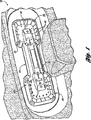
図1を参照すると、例示的実施形態に係るインストルメントクラスタ20が示されている。インストルメントクラスタ20は、複数の自動車システムからの自動車データを、自動車の運転者および/または自動車の同乗者に供給するように構成された部品の集合体である。インストルメントクラスタ20はハウジング22を備えている。このハウジング22は、自動車のインストルメントパネル10に固定されるように構成され、運転者の前方や、中央スタックなどの付近、またさらには車両のヘッドライナーに結合された頭上コンポーネント内など、インストルメントパネル10の1つ以上の位置で、固定されている。図3は、装着領域24においてインストルメントパネル10に結合されたインストルメントクラスタ20を示している。インストルメントクラスタ20は自動車に用いるのに好適であるが、その自動車は、車(car)、ミニバン、トラックなどの陸上輸送に使用されるいかなる乗用車両であってもよい。別の実施形態によれば、インストルメントクラスタおよびパネルは、水上乗物、航空機など、いかなる種類の乗物で使用されてもよい。
Referring to FIG. 1, an
例示的実施形態によれば、図1および図5に最もよく示しているように、インストルメントクラスタ20は、スピードメーター表示部26と、エンジン毎分回転数(RPM)表示部28と、複数の自動車データを表示するように構成された表示部30とを備えている。自動車データとしては、スピード、エンジンRPM、エンジンオイル温度、燃料の残存量、エンジンオイルレベル、エンジン水温、エンジンオイル圧力、瞬間消費量、ターボ率、バッテリレベル、シートベルトインジケータ、ウインドシールト洗浄レベル、ハザードライトインジケータ、および/または他の情報が挙げられる。インストルメントクラスタ20は、示した表示部と同程度のものを含むことができる。
According to an exemplary embodiment, as best shown in FIGS. 1 and 5, the
ここで図2Aおよび図2Bを参照すると、インストルメントクラスタ20およびライトパイプ40がより詳細に示されている。インストルメントクラスタ20は、ハウジング22と、複数の照明装置52(例えば光源)を有するプリント回路基板32と、スピードおよびRPMのマーキングなどのしるし38を有するアップリケ36と、光透過性部分または目盛マーク42(例えば、線、矢印、円など)の形式で形成されてもよいライトガイドまたはライトパイプ40(例えば、光を透過させるように構成されたプラスチックまたは他の材料)と、部分的に半透明のアップリケ44(例えば、マジックミラー)と、レンズ48(任意選択)を有するベゼル46と、サブアセンブリ50とを備えている。例示的実施形態によれば、プリント回路基板は制御回路を含んでいてもよく、また制御回路に結合されていてもよい。プリント回路基板に結合された制御回路および/または制御回路を備えたプリント回路基板は、1つ以上のアナログおよび/またはデジタル式の電気または電子部品を備えることができ、また、マイクロプロセッサ、マクロコントローラ、特定用途向け集積回路(ASIC)、プログラマブルロジック、および/または他の回路素子を含むことができる。例示的実施形態によれば、制御回路は、自動車内で、複数の自動車システムから1つ以上の電線またはバスを介してデータを受信するように構成されている。例えば、制御回路は、自動車上で、燃料レベルセンサーから燃料データを受信し、エンジンオイル温度センサーからエンジンオイル温度データを受信するように構成することができる。様々な例示的実施形態によれば、回路基板は、プリント回路基板、フレキシブル回路基板、リジッド回路基板、導体箔、および/または他の好適な形態であってもよい。
2A and 2B, the
例示的実施形態によれば、複数の照明装置52は、プリント回路基板32上の発光ダイオード(LED)34を備えており、その発光ダイオード34は、ライトパイプ40上の目盛マーク42を介して光を透過させて、部分的に半透明のアップリケ44を介して表示部に照明をもたらす。ライトパイプ40、目盛マーク42および部分的に半透明のアップリケ44、または他の表示面を介して光が伝わることにより、自動車データの様々な値を表す線、マーク、または他のしるし(図1および図5に示す3次元照明領域43など)が提供され、指針は、各自動車システムによって感知した自動車データまたはパラメータの特定の値を示す。図1、図2A、および図5に示すように、アップリケ44は、概ね平坦でない部分45を少なくとも備えている。
According to an exemplary embodiment, the plurality of lighting devices 52 includes a light emitting diode (LED) 34 on a printed
図1および図5に示す例示的実施形態によれば、インストルメントクラスタ20は、LED34に照らされることによって3次元的に見えるように構成された照明領域43を有している。ライトパイプ40は、部分的に半透明のアップリケ44の裏側に取り付けられるように構成され、LED34が発光すると、目盛マーク42が車両の運転者および/または乗員によって観測可能かつ/または検出可能となるようになっている。さらに、アップリケ44は、LEDが発光していないとき、車両の乗員および/または運転者が目盛マーク42を観測することがないように構成されている。乗員および/または運転者の視点(例えば、車両の乗員領域)から見ると、アップリケ44は、この例示的実施形態においてはマジックミラーとして作用しており、LED34が発光していないときには(LED34からの)アップリケ44を透過する光よりも多くの光を(車両の同乗者領域から)反射する。図4は、LEDが発光していないとき(例えば、反射光が透過光よりも強い場合)のアップリケ44を示すものである。LED34からの光がなければ、照明領域43は、インストルメントクラスタ20の周囲に沿って視認できない。しかしながら、LED34が発光しているときには、アップリケ44は、アップリケ44によって反射されるよりも多くの光を、(LED34から)ライトパイプ40および目盛マーク42を介して透過させる。図1および図5は、LED34が発光して3次元的な「浮き上がる」目盛マークまたは照明領域を生成しているとき(例えば、透過光が反射光よりも強い場合)のアップリケ44を示すものである。
According to the exemplary embodiment shown in FIGS. 1 and 5, the
様々な例示的実施形態によれば、目盛マークおよび/または照明領域は、LEDが発光しているとき、昼夜観測可能である。別の実施形態によれば、複数(かつ/または全て)の目盛マークまたは光透過性部分を照明する単一のLEDなどの単一の照明装置によって、2つ以上の目盛マークが照明されてもよい。様々な実施形態によれば、ライトパイプ、目盛マークおよび照明領域は、任意の数の形状であってもよい。例えば、目盛マークおよび照明領域は、楕円形状、三角形状、矩形状、3次元状、2次元状などであってもよい。ライトパイプは、円形状、矩形状、U字型状などを含む複数の形状であってもよい。 According to various exemplary embodiments, tick marks and / or illuminated areas are observable day and night when the LEDs are emitting light. According to another embodiment, two or more graduation marks may be illuminated by a single illumination device, such as a single LED that illuminates a plurality (and / or all) of graduation marks or light transmissive portions. Good. According to various embodiments, the light pipes, tick marks and illumination areas may be any number of shapes. For example, the scale mark and the illumination area may be elliptical, triangular, rectangular, three-dimensional, two-dimensional, or the like. The light pipe may have a plurality of shapes including a circular shape, a rectangular shape, a U-shape, and the like.
図5に示す例示的実施形態によれば、部分的に半透明のアップリケ44は、金属様の外観または箔状の外観を有している。アップリケ44は、反射性の金属材料またはコーティング60を備えた処理剤を前面58に含んで、ベゼルのような外観を形成することができる。車両の同乗者領域からの光を反射させ、さらにLED34からの放出光をライトパイプ40および目盛マーク42を介して透過させるために、コーティング60によって、アップリケ44は少なくとも部分的に半透明にすることができる。
According to the exemplary embodiment shown in FIG. 5, the partially translucent applique 44 has a metal-like or foil-like appearance. The appliqué 44 may include a reflective metal material or treatment with a coating 60 on the front surface 58 to form a bezel-like appearance. The appliqué 44 is at least partially translucent by the coating 60 to reflect light from the passenger area of the vehicle and to allow light emitted from the LED 34 to pass through the
図3に示すように、インストルメントクラスタ20は、支持部または連結具62(例えば、支柱、ハウジング22の一部分、インストルメントパネル10の一部分、別個の連結具、結合具、部材など)を用いてインストルメントパネル10に結合されており、したがって、インストルメントクラスタ20は、(距離D1で示すように)所定の距離だけインストルメントパネル10から延びている。インストルメントクラスタ20は、インストルメントパネル10の凹部または閉鎖部分64内で、インストルメントパネル10に連結されている。インストルメントクラスタ20の背面66とインストルメントパネル10の前面68との距離(例えばD1)は、様々な実施形態に従って変更することができる。例示的実施形態によれば、D1は、車両の乗員領域から(例えば乗員が)見るとインストルメントクラスタ20がインストルメントパネル10の前方に浮いて見えるような距離である。例示的実施形態によれば、連結具62は支柱70を備えており、その支柱70は、インストルメントパネル10の少なくとも一部分に(例えば、インストルメントパネル内のアパーチャまたは開口部内に)固定されており、また、好適な方法に従ってインストルメントクラスタ20に結合されている。連結具62は、構造的で、電気的であり、また、構造的および電気的の双方の要素(例えば、電力、データなどのためのワイヤ)を有していてもよい。
As shown in FIG. 3, the
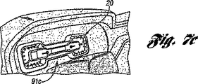
図1および図3は、インストルメントクラスタ20の周りの背景として、またはライトウォッシュ(light wash)として使用することができる点灯法を示す。図3は、インストルメントクラスタ20の後部分76の周囲に延びる照明装置72(例えばLED)を示す。照明装置72が発光すると、照明装置72はインストルメントパネル10の凹部64の前面68に対してライトウォッシュを生成する。インストルメントクラスタ20は、(乗員の視点からは実質的に隠れた)連結具62でインストルメントパネル10に結合されているため、光が凹部64の表面68全体に反射されることによって、ライトウォッシュは実質的にインストルメントクラスタ20を囲んでいるように見える。この構成によって、インストルメントクラスタ20に対する周囲の背景または点灯された背景がライトウォッシュによって形成され、インストルメントクラスタ20に対する「ふちなし」の外観が形成される。それによって、点灯および連結構成はクラスタが「浮き上がる」という錯覚をもたらす。様々な実施形態によれば、照明装置は、インストルメントクラスタの背面の様々な位置に配置された複数のライトを備えていてもよい。様々な実施形態によれば、ライトウォッシュの色は、時間と共にランダムに、乗員からの入力に基づいて、車両から得られたデータ(例えば、スピード、温度、燃料レベルなど)に基づいて変化してもよく、および/または、所定の期間を通じて依然として単一の色であってもよい。図6および図7は、クラスタ20に対する様々な点灯構成を示すものである。例えば、図6はクラスタ20に対する点灯手順を示すものであるが、その点灯手順において、ライトの色は、時間と共におよび/または使用者の入力もしくは車両データに基づいて変化する(例えば、青色90a、紫色90b、ピンク色90c、赤色90d、オレンジ色90e、緑色90f、または他の好適な色)。図7は、クラスタ20に対する異なる色テーマを示すものである(例えば、青色91a、緑色91b、オレンジ色91c、赤色91d、ピンク色91eなど)。言うまでもなく、ライトパイプ40(および目盛マーク42および照明領域43)は、何色のLEDが利用されているかに基づいて、任意の好適な色とすることができる(例えば、図5および図7においてはオレンジ色92a、図1においては赤色92bなど)。
FIGS. 1 and 3 illustrate a lighting scheme that can be used as a background around the
また、図5に示すように、インストルメントクラスタ20は、シート82上に設けられたしるし80を備えている。しるし80は、クラスタ20内に設けられた光源(例えばLED)によって照明される。しるし80は、(クラスタ20の縁部に相当する)シート82の縁部に配置されている。光源からの光は、ライトガイドまたはライトパイプによってしるし80へ伝えられる。ライトガイドはシートの一部分であってもよく、またシートから分離していてもよい。しるし80の目視方向に対して横向きに(例えば、目視方向がシートの表面を通過するシート深さにまで)光がシートに入るように、ライトガイドは角度をなすことができる。
As shown in FIG. 5, the
照明されていないとき、しるし80は第1の視覚状態を有することができ、その第1の視覚状態において、しるし80は目立たないものとなる。照明されているとき、しるし80は第2の視覚状態を有することができ、その第2の視覚状態において、しるし80はより目立つものとなる。様々なしるしが、第1の視覚状態から第2の視覚状態に個別に切り換えられてもよい。あるしるしの群は、第1の視覚状態から第2の視覚状態に同時に選択的に切り換えることができるように構成することができる。例示的実施形態によれば、しるしに対する第1の視覚状態と第2の視覚状態との間で高いコントラストが存在するように、光源は利用される。 When not illuminated, the indicia 80 can have a first visual state in which the indicia 80 is inconspicuous. When illuminated, the indicia 80 can have a second visual state in which the indicia 80 becomes more prominent. Various indicia may be individually switched from the first visual state to the second visual state. A group of indicia can be configured to be able to selectively switch from the first visual state to the second visual state simultaneously. According to an exemplary embodiment, the light source is utilized such that there is a high contrast between the first visual state and the second visual state for the indicia.
半透明のシート内に送り込まれる光を外向きに透過させる視覚的マークを形成するように、しるし80は、シートの形状を分裂することによって、半透明のシート内に埋め込まれていてもよい。この埋込みは、シートをエッチングするか、シートのトポグラフィーを変更するか、シートをエンボス加工するか、シートをツールテクスチャリングするか、インモールドグラフィックをシートに転写するか、シートを箔塗装するか、シートの結晶構造を変化させることによって、または他の任意の好適な技法によって行うことができる。一実施形態によれば、しるしは、シートが形成される成形段階において追加される。しるしは、結果として生じる像が3次元的な外観を有するように、半透明のシート内に3次元で(例えば、3次元の像をシート内にレーザエッチングすることによって)形成することができる。3次元の像は、他の製品に3次元の像を形成するために3MまたはCrystology 3−Dによって使用されているものと類似した技法を用いて形成することができる。 The indicia 80 may be embedded in the translucent sheet by disrupting the shape of the sheet so as to form a visual mark that transmits outward light transmitted into the translucent sheet. This embedding can be done by etching the sheet, changing the topography of the sheet, embossing the sheet, tool texturing the sheet, transferring in-mold graphics to the sheet, or foil coating the sheet. , By changing the crystal structure of the sheet, or by any other suitable technique. According to one embodiment, indicia are added at the molding stage where the sheet is formed. Indicia can be formed in three dimensions in a translucent sheet (eg, by laser etching a three dimensional image into the sheet) such that the resulting image has a three dimensional appearance. Three-dimensional images can be formed using techniques similar to those used by 3M or Crystallography 3-D to form three-dimensional images on other products.
しるし80は表示器(tell-tale)として示されているが、目盛マーク、数、図形(棒グラフなど)、方向指示器、または他の種類のしるしの形を取ることもできる。いくつかの実施形態において、しるしは、情報を知らせるものではない点灯効果(エッジ点灯効果など)をもたらすために用いられてもよい。様々な実施形態によれば、しるしは共通の色を有するように照明されてもよく、また異なる色を有するように照明されてもよい。さらに、複数のしるしが、共通の方法によって、または異なる複数の方法によって形成されてもよい。 Indicia 80 is shown as a tell-tale, but may take the form of tick marks, numbers, graphics (such as bar graphs), turn indicators, or other types of indicia. In some embodiments, indicia may be used to provide lighting effects (such as edge lighting effects) that do not inform information. According to various embodiments, the indicia may be illuminated to have a common color or may be illuminated to have a different color. Further, the plurality of indicia may be formed by a common method or by a plurality of different methods.
いくつかの実施形態において、シートは、様々なしるしが互いに区別されるように構成されていてもよい。このことは、あるしるしから別のしるしへとシートを伝わる光の量を減じるのに役立てることができる。しるしは、シート内のしるしの間にある成形された刻み目、シート内のしるしの間にある切れ目を用いることによって、または、しるしの間に遮光性領域を形成するための他の何らかの方法を用いることによって、互いに区別することができる。しるしの区別は、光をシートに案内するためにライトガイドが使用されていない(例えば、光源がシートの入口に近接して装着されている)とき、または、より明るい光源が使用されているときにより必要となる傾向がある。 In some embodiments, the sheet may be configured such that various indicia are distinguished from each other. This can help reduce the amount of light traveling through the sheet from one sign to another. The indicia may be by using shaped indentations between the indicia in the sheet, cuts in between the indicia in the sheet, or using some other method for forming a light-blocking area between the indicia. Can be distinguished from each other. The distinction between indicia is when a light guide is not used to guide light to the sheet (eg when a light source is mounted close to the entrance of the sheet) or when a brighter light source is used. Tend to be needed.
任意の数の形状が、インストルメントクラスタの構成要素または部品に使用されてもよい。例えば、アップリケ、シート、およびライトパイプは、平面状であっても、非平面状であっても、曲線状であっても、矩形状であっても、卵のような形状であっても、不規則な形状であっても、厚くても、1枚のフィルムであってもよく、また、他の何らかの好適な形をなしていてもよい。これらの部品は半透明であってもよい。これらの部品は、プラスチックから形成されていても、ポリマーから形成されていても、ガラス、アクリルおよび/または他の好適な材料から形成されてもよい。例示的な実施形態によれば、インストルメントクラスタの従来型レンズはシートとして役立ちうるが、そのシートはプラスチック材料から形成されていてもよく、また実質的に平面的な形を備えていてもよい。澄んだシートおよびライトパイプは、光をより良好に透過させる。照明されるしるしおよび/または目盛マークの位置に十分な量の光が到達できるようにする反面、1つのしるしおよび/または目盛マークからの光がシートまたはライトパイプによって伝えられて他のしるしに達し、そのしるしを照明することがほとんどないように、シートおよびライトパイプの透明性、光源の輝度、および他の様々な要素は好ましく選択される。 Any number of shapes may be used for the components or parts of the instrument cluster. For example, appliques, sheets, and light pipes may be planar, non-planar, curved, rectangular, egg-like, It may be irregularly shaped, thick, a single film, or may have any other suitable shape. These parts may be translucent. These parts may be formed from plastic, from polymer, from glass, acrylic and / or other suitable materials. According to an exemplary embodiment, a conventional lens of an instrument cluster can serve as a sheet, but the sheet may be formed from a plastic material and may have a substantially planar shape. . Clear sheets and light pipes transmit light better. While allowing a sufficient amount of light to reach the location of the illuminated indicia and / or graduation mark, the light from one indicia and / or graduation mark is transmitted by the sheet or light pipe to reach the other indicia. The transparency of the sheet and light pipe, the brightness of the light source, and various other factors are preferably selected so that the indicia is rarely illuminated.
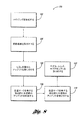
図8を参照すると、インストルメントクラスタを形成する方法100が示されている。この方法は、後部分に光源を有するハウジングを形成するブロック102のステップと、LEDを有する回路基板をハウジングに取り付けるブロック104のステップと、しるし(例えば、RPMおよび/または車両速度のマーク)を備えたアップリケを取り付けるブロック106のステップと、光透過性部分または目盛マークを有するライトパイプを部分的に半透明のアップリケに貼り付け、(3次元の)目盛マークを有する部分的に半透明のアップリケを形成するブロック108のステップと、(3次元の)目盛マークを有する部分的に半透明のアップリケをハウジングに取り付けるブロック110のステップと、ベゼル、レンズおよびサブアセンブリをハウジングに取り付けるブロック112のステップとを含んでいる。この方法は、しるしを備えたシートを取り付けるステップと、ライトパイプ、目盛マーク、しるしおよびインストルメントクラスタの後部領域を照明するステップを含んでいてもよい。しるしを備えたシートを形成するステップは、しるしを備えるように設定された方式でシートを成形するステップ(例えば、しるしを互いに分離するステップ、成形された刻み目を利用するステップ、シートをエッチングするステップ、シートのトポグラフィーを変更するステップ、シートをエンボス加工するステップ、シートをツールテクスチャリングするステップ、インモールドグラフィックをシートに転写するステップ、シートを箔塗装するステップ、これらのステップの組合せ、または他のステップ)を含んでいてもよい。
Referring to FIG. 8, a
各ブロックにおける構成要素の取り付けには、スナップ連結、クリップ連結、接着剤、溶接(例えば、音波、レーザーなど)、および/または他の好適な手段を使用することを含んでいてもよい。光源からの照明は、1つまたは2つ以上の光源でしるしを照明することを含んでいてもよい。照明は、測定されたパラメータの値に応答するものでも、車両状態の変化に応答するものでも、かつ/または使用者の入力に応答するものであってもよい。照明はエンジンの点火に基づいたものであってもよく、かつ/または、装備品の状態の変化(例えば、ラジオ、空気調和、熱、室内灯、ナビゲーションシステムなど)に応じたものであってもよい。 Attachment of the components in each block may include using snap connections, clip connections, adhesives, welding (eg, sonic, laser, etc.), and / or other suitable means. Illumination from the light source may include illuminating the indicia with one or more light sources. The lighting may be responsive to measured parameter values, responsive to changes in vehicle conditions, and / or responsive to user input. The lighting may be based on engine ignition and / or in response to changes in equipment conditions (eg radio, air conditioning, heat, room lights, navigation systems, etc.) Good.
例示的実施形態、好ましい実施形態、および別の実施形態に示すシステムの要素の構成および配置は、例示的なものに過ぎない。少数の実施形態についてのみ本開示において詳細に説明したが、本開示を検討する当業者であれば、記載した主題の新規な教示および利点から大きく逸脱することなく、多数の修正(例えば、様々な要素の寸法、大きさ、構造、形状および釣合い、パラメータの値、固定装置、材料の使用、色、向きなどの変更)が可能であることを容易に理解できるであろう。例えば、一体に形成されているように示した要素は、複数の部品から構成されていてもよく、また、複数の部品として示した要素は、一体に形成されていてもよく、締結具、連結具などの操作は、逆に行われても、あるいは変更などされてもよい。留意してもらいたいこととして、システムの要素および/またはアセンブリは、広範な色、テクスチャおよび組合せにおける広範な成形用プラスチック材料(耐衝撃プラスチックまたは様々な被覆(硬質被覆材料など)を有するプラスチックなど)を含めて、十分な強度または耐久性のある広範な材料から構成されていてもよい。さらに、留意してもらいたいこととして、システムは、デジタルディスプレイ、電子ディスプレイなどのような広範な種類の構成要素および/または特徴のいずれと共に使用されてもよい。したがって、そのようなすべての修正は、本システムの範囲内に含まれることを意図している。本システムの範囲から逸脱することなく、好ましい実施形態および他の例示的実施形態の設計、動作条件および構成において、他の代替、修正、変更および省略を行うことができる。 The configuration and arrangement of system elements shown in the exemplary, preferred, and alternative embodiments are merely exemplary. Although only a few embodiments have been described in detail in this disclosure, those of ordinary skill in the art who have reviewed the disclosure will recognize numerous modifications (eg, various variations) without departing significantly from the novel teachings and advantages of the described subject matter. It will be readily understood that changes in element size, size, structure, shape and balance, parameter values, fixation devices, use of materials, color, orientation, etc. are possible. For example, an element shown as being integrally formed may be composed of a plurality of parts, and an element shown as a plurality of parts may be integrally formed as a fastener, coupling The operation of the tool or the like may be performed in reverse or may be changed. It should be noted that system elements and / or assemblies can be used in a wide range of molding plastic materials in a wide range of colors, textures and combinations (such as impact resistant plastics or plastics with various coatings (such as hard coating materials)). Including a wide range of materials having sufficient strength or durability. Further, it should be noted that the system may be used with any of a wide variety of components and / or features such as digital displays, electronic displays, and the like. Accordingly, all such modifications are intended to be included within the scope of the system. Other substitutions, modifications, changes and omissions may be made in the design, operating conditions and configurations of the preferred and other exemplary embodiments without departing from the scope of the present system.
Claims (11)
複数の照明装置(52)を備えた回路基板(32)と、
部分的に半透明のアップリケ(44)と、
前記部分的に半透明のアップリケ(44)と前記回路基板(32)の間に配置された複数の光透過性部分(40)とを備え、
前記複数の照明装置(52)は、前記複数の光透過性部分(40)を照らすように構成され、
前記部分的に半透明のアップリケ(44)の前面(58)は、前記複数の照明装置(52)によって照らされていない時には前記複数の光透過性部分(40)が車両の乗員に視認できず前記複数の照明装置(52)によって照らされている時には前記複数の光透過性部分(40)が車両の乗員に視認できるような程度に前記車両の同乗者領域に向かって光を反射させるために少なくとも部分的に処理されており、
前記複数の光透過性部分(40)は、前記複数の照明装置(52)がライトパイプ(40)を通して光を透過させた時に、前記車両の同乗者領域から見ると、3次元的な照明領域(43)の外観を前記部分的に半透明のアップリケ(44)上に形成するように構成されている、
インストルメントクラスタ(20)。An instrument cluster (20) for a passenger vehicle,
A circuit board (32) comprising a plurality of lighting devices (52) ;
A partially translucent applique (44) ;
A plurality of light transmissive portions (40) disposed between the partially translucent applique (44) and the circuit board (32) ;
Wherein the plurality of illumination devices (52) is composed of a plurality of light transmitting portions (40) to the irradiation Las so,
When the front surface (58) of the partially translucent applique (44) is not illuminated by the plurality of lighting devices (52), the plurality of light transmissive portions (40) are not visible to a vehicle occupant. In order to reflect light toward the passenger area of the vehicle to such an extent that the plurality of light transmissive portions (40) are visible to the vehicle occupant when illuminated by the plurality of lighting devices (52). At least partially processed,
The plurality of light transmissive portions (40) are three-dimensional illumination areas when viewed from the passenger area of the vehicle when the plurality of illumination devices (52) transmit light through the light pipe (40). (43) configured to form an appearance on the partially translucent applique (44) ,
Instrument cluster (20) .
前部および後部を有する少なくとも部分的に半透明の材料(44)と、
前記少なくとも部分的に半透明の材料(44)の後部に隣接する少なくとも1つのライトパイプ(40)と、
前記少なくとも1つのライトパイプ(40)において前記少なくとも部分的に半透明の材料(44)を介して光を透過させるように構成された光源(52)と、
前記少なくとも部分的に半透明の材料(44)と前記光源(52)の間に配置された複数の光透過性部分(40)とを備え、
前記少なくとも部分的に半透明の材料(44)は、前記車両の同乗者領域に向かって光を反射させるように構成され、
前記少なくとも部分的に半透明の材料(44)は、前記光源(52)が発光するときに、前記光源(52)によって照らされていない時には前記複数の光透過性部分(40)が車両の乗員に視認できず前記光源(52)によって照らされている時には前記複数の光透過性部分(40)が車両の乗員に視認できるような程度に前記少なくとも部分的に半透明の材料(44)を透過する光よりも少ない光を反射させるように構成されており、
前記複数の光透過性部分(40)は、前記光源(52)が前記少なくとも1つのライトパイプ(40)を通して光を透過させた時に、前記車両の同乗者領域から見ると、3次元的な照明領域(43)の外観を前記少なくとも部分的に半透明の材料(44)上に形成するように構成されている、
インストルメントクラスタ(20)。An instrument cluster (20) for a passenger vehicle,
At least partially translucent material (44) having a front portion and a rear portion;
At least one light pipe (40) adjacent to the rear of the at least partially translucent material (44) ;
A light source (52) configured to transmit light through the at least partially translucent material (44) in the at least one light pipe (40) ;
A plurality of light transmissive portions (40) disposed between the at least partially translucent material (44) and the light source (52) ;
The at least partially translucent material (44) is configured to reflect light toward a passenger area of the vehicle;
The at least partially translucent material (44) is such that when the light source (52) emits light, the plurality of light transmissive portions (40) are occupant of a vehicle when not illuminated by the light source (52). The at least partially translucent material (44) is transmitted to such an extent that the plurality of light transmissive portions (40) are visible to a vehicle occupant when illuminated by the light source (52). It is configured to reflect less light than it does,
The plurality of light transmissive portions (40) are three-dimensional illumination when viewed from the passenger area of the vehicle when the light source (52) transmits light through the at least one light pipe (40). Configured to form the appearance of region (43) on said at least partially translucent material (44) ;
Instrument cluster (20) .
Applications Claiming Priority (3)
| Application Number | Priority Date | Filing Date | Title |
|---|---|---|---|
| US64223905P | 2005-01-07 | 2005-01-07 | |
| US60/642,239 | 2005-01-07 | ||
| PCT/US2006/000429 WO2006074349A2 (en) | 2005-01-07 | 2006-01-06 | Instrument cluster |
Publications (2)
| Publication Number | Publication Date |
|---|---|
| JP2008526601A JP2008526601A (en) | 2008-07-24 |
| JP4939435B2 true JP4939435B2 (en) | 2012-05-23 |
Family
ID=36250883
Family Applications (1)
| Application Number | Title | Priority Date | Filing Date |
|---|---|---|---|
| JP2007550490A Expired - Fee Related JP4939435B2 (en) | 2005-01-07 | 2006-01-06 | Instrument cluster |
Country Status (7)
| Country | Link |
|---|---|
| US (1) | US20080219018A1 (en) |
| EP (1) | EP1838552B1 (en) |
| JP (1) | JP4939435B2 (en) |
| CN (1) | CN101146690B (en) |
| AT (1) | ATE533661T1 (en) |
| PL (1) | PL1838552T3 (en) |
| WO (1) | WO2006074349A2 (en) |
Families Citing this family (20)
| Publication number | Priority date | Publication date | Assignee | Title |
|---|---|---|---|---|
| US20080164865A1 (en) * | 2007-01-05 | 2008-07-10 | Ford Global Technologies, Llc | Display system for an automotive vehicle |
| JP5101986B2 (en) * | 2007-10-23 | 2012-12-19 | カルソニックカンセイ株式会社 | In-vehicle display device |
| WO2009077155A1 (en) * | 2007-12-14 | 2009-06-25 | Johnson Controls Technology Company | Vehicle interfaces |
| US7872570B2 (en) * | 2008-05-15 | 2011-01-18 | Havins William H | Informational display for rapid operator perception |
| GB2468290A (en) * | 2009-03-03 | 2010-09-08 | Nissan Motor Mfg | Vehicle instrument display |
| US20110130929A1 (en) * | 2009-12-01 | 2011-06-02 | Chang Ten-Lee | Smart electronic transmission control system |
| JP5487075B2 (en) * | 2010-10-26 | 2014-05-07 | 矢崎総業株式会社 | Automotive instrument |
| US9233609B2 (en) * | 2012-01-06 | 2016-01-12 | Visteon Global Technologies, Inc. | Transmissive display over gauge |
| JP5871692B2 (en) * | 2012-03-29 | 2016-03-01 | 本田技研工業株式会社 | Vehicle traction control display device |
| JP6008195B2 (en) * | 2013-01-09 | 2016-10-19 | 日本精機株式会社 | Instrument device |
| US9568655B2 (en) | 2013-12-26 | 2017-02-14 | Visteon Global Technologies, Inc. | Backlight assembly |
| DE102014201885A1 (en) * | 2014-02-03 | 2015-08-06 | Johnson Controls Automotive Electronics Gmbh | Cover for at least one display instrument in a vehicle |
| MX341222B (en) * | 2014-03-24 | 2016-08-11 | Magneti Marelli Spa | Vehicle instrument panel equipped with a led backlighting device for lighting a graphic area. |
| DE102015104299A1 (en) | 2015-03-23 | 2016-09-29 | International Automotive Components Group Gmbh | Interior trim part for a motor vehicle |
| JP2016185762A (en) * | 2015-03-27 | 2016-10-27 | 株式会社オートネットワーク技術研究所 | On-board light emitting device |
| US9834092B2 (en) * | 2015-05-11 | 2017-12-05 | Visteon Global Technologies, Inc. | Linear bar graph |
| US10596905B2 (en) | 2017-01-02 | 2020-03-24 | Visteon Global Technologies, Inc. | Selective lighting for indicia |
| US11046185B1 (en) | 2020-06-17 | 2021-06-29 | N.S. International Ltd. | Lensless instrument cluster with integration of hard telltales and halo lighting providing a seamless display appearance |
| US11535103B2 (en) | 2020-06-17 | 2022-12-27 | N. S. International Ltd. | Lensless instrument cluster with integration of hard telltales and halo lighting providing a seamless display appearance |
| CN112856353B (en) * | 2020-12-23 | 2022-10-25 | 中国商用飞机有限责任公司 | Light shield integrated with OLED lamp |
Citations (5)
| Publication number | Priority date | Publication date | Assignee | Title |
|---|---|---|---|---|
| GB2266374A (en) * | 1992-04-21 | 1993-10-27 | Delco Electronics Corp | Display apparatus |
| US20020085366A1 (en) * | 2000-12-29 | 2002-07-04 | Angell Daniel K. | Thin panel lit cluster |
| DE10314473A1 (en) * | 2002-04-05 | 2003-11-13 | Siemens Vdo Automotive Corp | Combination instrument, especially for semitransparent instrument panel, has primary optical system that directs light to semitransparent screen to display image of variable vehicle condition(s) |
| JP2004198241A (en) * | 2002-12-18 | 2004-07-15 | Denso Corp | Gauge |
| JP2006526141A (en) * | 2003-05-13 | 2006-11-16 | シーメンス・ブイディーオー・オートモーティブ・コーポレイション | Gauge display scale lighting |
Family Cites Families (14)
| Publication number | Priority date | Publication date | Assignee | Title |
|---|---|---|---|---|
| US4991064A (en) * | 1989-12-05 | 1991-02-05 | Delco Electronics Corporation | Silhouette lightpipe illumination for vehicle instrumentation |
| US5971558A (en) * | 1996-06-06 | 1999-10-26 | Kuhlman Corporation | Method and apparatus for mounting an instrument |
| FR2763027B1 (en) * | 1997-05-12 | 1999-06-25 | Valeo Electronique | IMPROVEMENT ON CONTROL PANELS, PARTICULARLY FOR HEATING, VENTILATION AND / OR AIR CONDITIONING OF THE INTERIOR OF A MOTOR VEHICLE |
| ES2282071T3 (en) * | 1999-09-07 | 2007-10-16 | Siemens Aktiengesellschaft | INDICATOR DEVICE. |
| DE10102774A1 (en) * | 2001-01-23 | 2002-08-14 | Bosch Gmbh Robert | Dashboard dial display for a motor vehicle has a light guide device behind a partially transparent display surface with limited areas of brightness enhancement film on the inner surface of the light guide to improve light yield |
| US6568345B1 (en) * | 2001-08-06 | 2003-05-27 | Yazaki North America, Inc. | Selectable instrument clusters |
| JP3786033B2 (en) * | 2001-10-31 | 2006-06-14 | 豊田合成株式会社 | Meter display system |
| US6663252B1 (en) * | 2002-01-28 | 2003-12-16 | Yazaki North America, Inc. | Automotive display panel |
| DE10220335B4 (en) * | 2002-05-07 | 2006-05-24 | Siemens Ag | display |
| US6840654B2 (en) * | 2002-11-20 | 2005-01-11 | Acolyte Technologies Corp. | LED light and reflector |
| JP2004309241A (en) * | 2003-04-04 | 2004-11-04 | Yamaha Motor Co Ltd | Display for saddle type vehicle |
| JP4329061B2 (en) * | 2003-04-25 | 2009-09-09 | 日本精機株式会社 | Instrument device |
| US7246911B2 (en) * | 2004-10-07 | 2007-07-24 | Yazaki North America, Inc. | Instrument cluster with hidden telltale indicators |
| US7077535B2 (en) * | 2004-12-07 | 2006-07-18 | Shih-Hsiung Wu | Automobile instrument panel lighting structure |
-
2006
- 2006-01-06 WO PCT/US2006/000429 patent/WO2006074349A2/en active Application Filing
- 2006-01-06 US US11/813,412 patent/US20080219018A1/en not_active Abandoned
- 2006-01-06 PL PL06717604T patent/PL1838552T3/en unknown
- 2006-01-06 CN CN2006800063748A patent/CN101146690B/en not_active Expired - Fee Related
- 2006-01-06 JP JP2007550490A patent/JP4939435B2/en not_active Expired - Fee Related
- 2006-01-06 EP EP06717604A patent/EP1838552B1/en not_active Not-in-force
- 2006-01-06 AT AT06717604T patent/ATE533661T1/en active
Patent Citations (5)
| Publication number | Priority date | Publication date | Assignee | Title |
|---|---|---|---|---|
| GB2266374A (en) * | 1992-04-21 | 1993-10-27 | Delco Electronics Corp | Display apparatus |
| US20020085366A1 (en) * | 2000-12-29 | 2002-07-04 | Angell Daniel K. | Thin panel lit cluster |
| DE10314473A1 (en) * | 2002-04-05 | 2003-11-13 | Siemens Vdo Automotive Corp | Combination instrument, especially for semitransparent instrument panel, has primary optical system that directs light to semitransparent screen to display image of variable vehicle condition(s) |
| JP2004198241A (en) * | 2002-12-18 | 2004-07-15 | Denso Corp | Gauge |
| JP2006526141A (en) * | 2003-05-13 | 2006-11-16 | シーメンス・ブイディーオー・オートモーティブ・コーポレイション | Gauge display scale lighting |
Also Published As
| Publication number | Publication date |
|---|---|
| WO2006074349A3 (en) | 2007-03-29 |
| PL1838552T3 (en) | 2012-04-30 |
| JP2008526601A (en) | 2008-07-24 |
| WO2006074349A2 (en) | 2006-07-13 |
| ATE533661T1 (en) | 2011-12-15 |
| EP1838552A2 (en) | 2007-10-03 |
| CN101146690B (en) | 2012-01-04 |
| US20080219018A1 (en) | 2008-09-11 |
| EP1838552B1 (en) | 2011-11-16 |
| CN101146690A (en) | 2008-03-19 |
Similar Documents
| Publication | Publication Date | Title |
|---|---|---|
| JP4939435B2 (en) | Instrument cluster | |
| JP2009504502A (en) | Illuminated trim elements for instrument clusters | |
| US20090121853A1 (en) | Instrument cluster lens information, telltails, and lighting | |
| JP5476459B2 (en) | Interactive display and gauge | |
| US7553036B2 (en) | Display device | |
| US7121674B2 (en) | Illuminable display | |
| US20070052703A1 (en) | Display device | |
| JP2006201038A (en) | Display device | |
| US20080186155A1 (en) | Persistence of Vision Display | |
| US6404333B1 (en) | Gauge instrument for use in a motor vehicle | |
| US20180361920A1 (en) | Light guide with chaplet tick marks | |
| JP4797696B2 (en) | Display device | |
| JP2013142694A (en) | Transmissive display over gauge | |
| US7537354B2 (en) | Three dimensional image illumination for instrument gauge | |
| JP2003329491A (en) | Pointer type measuring instrument | |
| JP5343895B2 (en) | Display device | |
| EP3696004B1 (en) | Display arrangement for an instrument cluster | |
| US10829039B2 (en) | Display arrangement for an instrument cluster | |
| JP2003216077A (en) | Display plate | |
| JP2007327793A (en) | Pointer meter | |
| JP2006103508A (en) | Vehicular display device | |
| KR980008710A (en) | Clusters of cars |
Legal Events
| Date | Code | Title | Description |
|---|---|---|---|
| A621 | Written request for application examination |
Free format text: JAPANESE INTERMEDIATE CODE: A621 Effective date: 20081117 |
|
| A131 | Notification of reasons for refusal |
Free format text: JAPANESE INTERMEDIATE CODE: A131 Effective date: 20101109 |
|
| A601 | Written request for extension of time |
Free format text: JAPANESE INTERMEDIATE CODE: A601 Effective date: 20110208 |
|
| A602 | Written permission of extension of time |
Free format text: JAPANESE INTERMEDIATE CODE: A602 Effective date: 20110216 |
|
| A521 | Request for written amendment filed |
Free format text: JAPANESE INTERMEDIATE CODE: A523 Effective date: 20110509 |
|
| A131 | Notification of reasons for refusal |
Free format text: JAPANESE INTERMEDIATE CODE: A131 Effective date: 20110614 |
|
| A601 | Written request for extension of time |
Free format text: JAPANESE INTERMEDIATE CODE: A601 Effective date: 20110913 |
|
| A602 | Written permission of extension of time |
Free format text: JAPANESE INTERMEDIATE CODE: A602 Effective date: 20110921 |
|
| A521 | Request for written amendment filed |
Free format text: JAPANESE INTERMEDIATE CODE: A523 Effective date: 20111124 |
|
| TRDD | Decision of grant or rejection written | ||
| A01 | Written decision to grant a patent or to grant a registration (utility model) |
Free format text: JAPANESE INTERMEDIATE CODE: A01 Effective date: 20120131 |
|
| A01 | Written decision to grant a patent or to grant a registration (utility model) |
Free format text: JAPANESE INTERMEDIATE CODE: A01 |
|
| A61 | First payment of annual fees (during grant procedure) |
Free format text: JAPANESE INTERMEDIATE CODE: A61 Effective date: 20120224 |
|
| FPAY | Renewal fee payment (event date is renewal date of database) |
Free format text: PAYMENT UNTIL: 20150302 Year of fee payment: 3 |
|
| R150 | Certificate of patent or registration of utility model |
Ref document number: 4939435 Country of ref document: JP Free format text: JAPANESE INTERMEDIATE CODE: R150 Free format text: JAPANESE INTERMEDIATE CODE: R150 |
|
| R250 | Receipt of annual fees |
Free format text: JAPANESE INTERMEDIATE CODE: R250 |
|
| R250 | Receipt of annual fees |
Free format text: JAPANESE INTERMEDIATE CODE: R250 |
|
| R250 | Receipt of annual fees |
Free format text: JAPANESE INTERMEDIATE CODE: R250 |
|
| R250 | Receipt of annual fees |
Free format text: JAPANESE INTERMEDIATE CODE: R250 |
|
| R250 | Receipt of annual fees |
Free format text: JAPANESE INTERMEDIATE CODE: R250 |
|
| LAPS | Cancellation because of no payment of annual fees |