EP2679965A2 - Needle indicator oriented by periphery electromagnets - Google Patents
Needle indicator oriented by periphery electromagnets Download PDFInfo
- Publication number
- EP2679965A2 EP2679965A2 EP13173054.1A EP13173054A EP2679965A2 EP 2679965 A2 EP2679965 A2 EP 2679965A2 EP 13173054 A EP13173054 A EP 13173054A EP 2679965 A2 EP2679965 A2 EP 2679965A2
- Authority
- EP
- European Patent Office
- Prior art keywords
- pointer
- electromagnets
- assembly
- display
- instrument panel
- Prior art date
- Legal status (The legal status is an assumption and is not a legal conclusion. Google has not performed a legal analysis and makes no representation as to the accuracy of the status listed.)
- Withdrawn
Links
Images


Classifications
-
- G—PHYSICS
- G01—MEASURING; TESTING
- G01D—MEASURING NOT SPECIALLY ADAPTED FOR A SPECIFIC VARIABLE; ARRANGEMENTS FOR MEASURING TWO OR MORE VARIABLES NOT COVERED IN A SINGLE OTHER SUBCLASS; TARIFF METERING APPARATUS; MEASURING OR TESTING NOT OTHERWISE PROVIDED FOR
- G01D13/00—Component parts of indicators for measuring arrangements not specially adapted for a specific variable
- G01D13/02—Scales; Dials
- G01D13/04—Construction
Definitions
- This disclosure generally relates to vehicle instrument panels, and more particularly relates to a needle indicator that positions or orients a magnetized pointer using electromagnets arranged around a perimeter or periphery of the indicator.
- the permanent magnet and electro magnet undesirably obstruct too much of the reconfigurable display proximate to the axis. It has also been proposed that the permanent magnet and electromagnet be located behind the reconfigurable display, and the shaft extended through the reconfigurable display. However, this requires providing a hole in the reconfigurable display that makes manufacturing of the reconfigurable display undesirable complicated and costly.
- a needle indicator assembly includes a pointer and a plurality of electromagnets.
- the pointer is formed at least in part of magnetized material.
- the pointer is configured to rotate about an axis and thereby define an area swept by the pointer.
- the plurality of electromagnets is arranged around a perimeter of the area.
- the electromagnets are operable to urge the pointer to point in a desired direction.
- the assembly further comprises a lens formed of transparent material and arranged to overlay the area.
- the assembly further comprises a bearing coupled to the lens proximate the axis. The bearing is configured to rotationally support the pointer.
- the assembly further comprises a controller configured to independently operate each of the electromagnets to one of a NORTH-POLE state, a SOUTH-POLE state, and an OFF state.
- an instrument panel in another embodiment, includes a reconfigurable display, a magnetized pointer, and a plurality of electromagnets.
- the pointer overlies the display.
- the pointer is configured to rotate about an axis and thereby define an area swept by the pointer.
- the plurality of electromagnets is arranged around a perimeter of the area.
- the electromagnets are operable to urge the pointer to point in a desired direction.
- the instrument further comprises a housing configured to support the reconfigurable display, the magnetized pointer and the electromagnets.
- the housing is further configured to provide attachment features for securing the instrument panel to a vehicle dashboard.
- Fig. 1 is a perspective view of a vehicle interior equipped with an instrument panel that includes a needle pointer assembly in accordance with one embodiment
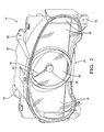
- Fig. 2 is a perspective view of the instrument panel of Fig. 1 in accordance with one embodiment
- Fig. 3 is an exploded perspective view of the instrument panel of Fig. 1 in accordance with one embodiment.
- Fig. 4 is a front view of the needle assembly of Fig. 3 in accordance with one embodiment.
- Fig. 1 illustrates a non-limiting example of a vehicle 10 equipped with an instrument panel 12 installed into a dashboard 16 of the vehicle 10.
- the instrument panel 12 displays information to an operator 14 of the vehicle 10 such as vehicle speed, engine coolant temperature, and the like.
- Fig. 2 illustrates a non-limiting example of the instrument panel 12 as it might appear when not installed into the dashboard 16 of the vehicle 10.
- the instrument panel 12 includes a reconfigurable display, hereafter the display 18.
- the display 18 spans most of the viewing area of the instrument panel 12.
- a reconfigurable display includes, but is not limited to, any device that can display images in a manner similar to a display screen on a personal computer.
- the display 18 may include arrays of light emitting diodes (i.e. an LED display) or liquid crystal devices (i.e. an LCD display).
- the display 18 may be an applique that defines various symbols which become visibly apparent to the operator 14 when suitably backlit. It is recognized that an applique would not be as versatile for displaying a wide variety of information, but is believed to be a lower cost alternative to a fully reconfigurable display.
- the instrument panel 12 also includes a needle indicator assembly 20 overlaying the display 18. In general, most of the area of the needle indicator assembly 20 is substantially transparent so the operator 14 can see through the needle indicator assembly 20 to see the display 18 behind the needle indicator assembly 20.
- Fig. 3 is an exploded view of Fig. 2 that further illustrates non-limiting features of the instrument panel 12.
- the needle indicator assembly 20 includes a magnetized pointer, hereafter the pointer 22, overlaying the display 18.
- the pointer 22 is configured to rotate about an axis 24, and so defines an area 26 swept by the pointer 22.
- the instrument panel 12 or the needle indicator assembly 20 may also include a lens 38 formed of transparent material and arranged to overlay the area 26.
- the lens 38 is part of a larger protective cover formed of transparent material so the operator 14 can see the display 18 behind the area 26 as well as outside the area 26.
- the pointer 22 may be characterized as magnetized as it may be entirely, or partially, formed of magnetic material.
- the magnetic material may be material suitable for making permanent magnets, or other ferromagnetic material such as iron.
- the pointer 22 may be formed entirely or partially of a permanent magnet, or material that can be temporarily magnetized in the presence of a magnetic field. If only a tip portion 40 ( Fig. 4 ) of the pointer 22 is formed of magnetic material, for example a permanent magnet, the remaining portion of the pointer 22 may be formed of a polymeric compound.
- the pointer 22 is formed partially or entirely of magnetic material so that the pointer 22 itself is urged to some particular orientation by a magnetic field in order to point in a desired direction 28 ( Fig. 4 ).
- This configuration advantageously avoids the more traditional configuration of having a separate permanent magnet coupled to the pointer by a shaft on the axis 24, and an electromagnet proximate to the separate permanent magnet, as these parts would undesirable obscure the view of the display 18 proximate the pointer 22.
- the needle indicator assembly 20 may include a plurality of electromagnets 32 arranged around a perimeter 34 of the area 26.
- the electromagnets 32 may be a coil of wire wound on an iron bobbin, and attached to a printed circuit board 36 or other suitable substrate.
- the coil of wire may be wound on a bobbin formed of polymeric material.
- each of the electromagnets 32 may include two conductive leads (not shown) coupled to an H-bridge circuit (not shown) so that a positive, negative, or zero current can be established in each of the electromagnets 32 and thereby generate a NORTH magnetic field, a SOUTH magnetic field, or a null or OFF magnetic field.
- the strength or intensity of the magnetic field is generally proportional to the magnitude of current flowing in an electromagnet.
- the magnitude of current may be controlled by pulse-width-modulation of the signal applied to the electromagnets 32. Accordingly, the electromagnets 32 are operable to urge the pointer 22 to point in a desired direction 28.
- Fig. 4 further illustrates the non-limiting example of the needle indicator where the tip portion 40 is formed of a permanent magnet 42 oriented as illustrated. It is recognized that other orientations of permanent magnet may also be suitable to urge the pointer 22 to point in the desired direction.
- the electromagnets 32 are oriented so that when a positive current is applied, a NORTH magnetic field is projected towards the center of the area 26, and a SOUTH magnetic field is projected away from the center of the area 26. If only one of the electromagnets 32 is energized, then the pointer 22 will be urged to a particular orientation. If an adjacent electromagnet is energized, then the pointer can be incrementally positioned away from the particular orientation. It should be apparent that by energizing combinations of the electromagnets 32 that the pointer can be incrementally positioned to any orientation, and is not limited to being positioned at only a number of distinct orientations corresponding to the number of the electromagnets 32.
- the instrument panel 12 may also include a housing configured to support the display 18, the magnetized pointer (the pointer 22), and the electromagnets 32.
- the housing 44 may also provide attachment features 46, such as mounting tabs or other means known in the art for securing the instrument panel 12 to the dashboard 16.
- the instrument panel 12 or the needle indicator assembly 20 may also include a bearing 46 coupled to the lens 38 proximate the axis 24 to rotationally support the pointer 22.
- the bearing 46 may include features known in the art to damp motion of the pointer 22, and may include an optional return spring (not shown) configured to urge the pointer to some preferred orientation when all the electromagnets 32 are deactivated. It should be recognized that the instrument panel 12 or the needle indicator assembly 20 do not require a return spring, but a return spring may be desired by some customers.
- the instrument panel 12 may also include a controller 48 configured to independently operate each of the electromagnets 32 to one of a NORTH-POLE state, a SOUTH-POLE state, and an OFF state. These states may be by way of applying, for example, a positive current, a negative current, or zero current, respectively.
- the controller 48 may include a processor such as a microprocessor or other control circuitry as should be evident to those in the art.
- the controller 48 may include memory, including non-volatile memory, such as electrically erasable programmable read-only memory (EEPROM) for storing one or more routines, thresholds and captured data. The one or more routines may be executed by the processor to perform steps for controlling the orientation of the pointer 22 to, for example, the desired direction 28.
- EEPROM electrically erasable programmable read-only memory
- the display 18 and the needle indicator assembly 20 may be cooperatively operated to provide a speedometer by the display 18 showing a circular arrangement of numbers corresponding to potential vehicle speeds in the area 26. Then, the needle indicator assembly 20 may be operated so the pointer 22 is oriented to indicate the present speed of the vehicle. However, if an indication of engine speed is desired, the display may be reconfigured to display a circular arrangement of numbers corresponding to potential engine speeds in the area 26. Then, the needle indicator assembly 20 may be operated so the pointer 22 is oriented to indicate the present revolutions per minute (RPM) speed of the engine.
- RPM revolutions per minute
- the configuration of the display may be altered by the operator 14 pressing a button on the dashboard 16 as suggested in Fig. 1 .
- an instrument panel 12 and a needle indicator assembly 20 is provided. These satisfy the desires of customers requiring a mechanical pointer in front of an LCD display, with no visible bridge between the pointer 22 and the display 18. As such, the pointer 22 appears to be floating above the display 18, creating for some an entertaining mystery as to how it functions.
Abstract
A needle indicator assembly (20) that includes a pointer (22) formed at least in part of magnetized material, and configured to rotate about an axis (24) and thereby define an area (26) swept by the pointer (22). The assembly also includes a plurality of electromagnets (32) arranged around a perimeter (34) of the area (26), said electromagnets (32) operable to urge the pointer (22) to point in a desired direction (28). An instrument panel (12) equipped this needle assembly overlying a reconfigurable display (18) gives the appearance that the pointer (22) is floating above the display (18), and the means by which the pointer (22) is moved is not readily apparent.
Description
- This disclosure generally relates to vehicle instrument panels, and more particularly relates to a needle indicator that positions or orients a magnetized pointer using electromagnets arranged around a perimeter or periphery of the indicator.
- Traditional vehicle instrument panel needle indicators or gauge pointers that are positioned or rotated about an axis are known. Such traditional needle indicators are rotated by a permanent magnet attached to a shaft that is coupled to the pointer and located at the axis. The permanent magnet is typically urged to some angle by an electromagnet. Reconfigurable instrument panels that use flat display technology such as arrays of light emitting diodes (i.e. LED display) or liquid crystal devices (i.e. LCD display) have been introduced. However, the flat, two-dimensional appearance of such displays is not as aesthetically pleasing to some customers as the traditional needle indicator type displays. It has been proposed that the reconfigurable display be overlaid with a needle indicator. However, the permanent magnet and electro magnet undesirably obstruct too much of the reconfigurable display proximate to the axis. It has also been proposed that the permanent magnet and electromagnet be located behind the reconfigurable display, and the shaft extended through the reconfigurable display. However, this requires providing a hole in the reconfigurable display that makes manufacturing of the reconfigurable display undesirable complicated and costly.
- In accordance with one embodiment, a needle indicator assembly is provided. The assembly includes a pointer and a plurality of electromagnets. The pointer is formed at least in part of magnetized material. The pointer is configured to rotate about an axis and thereby define an area swept by the pointer. The plurality of electromagnets is arranged around a perimeter of the area. The electromagnets are operable to urge the pointer to point in a desired direction. The assembly further comprises a lens formed of transparent material and arranged to overlay the area. The assembly further comprises a bearing coupled to the lens proximate the axis. The bearing is configured to rotationally support the pointer. The assembly further comprises a controller configured to independently operate each of the electromagnets to one of a NORTH-POLE state, a SOUTH-POLE state, and an OFF state.
- In another embodiment, an instrument panel is provided. The instrument panel includes a reconfigurable display, a magnetized pointer, and a plurality of electromagnets. The pointer overlies the display. The pointer is configured to rotate about an axis and thereby define an area swept by the pointer. The plurality of electromagnets is arranged around a perimeter of the area. The electromagnets are operable to urge the pointer to point in a desired direction. The instrument further comprises a housing configured to support the reconfigurable display, the magnetized pointer and the electromagnets. The housing is further configured to provide attachment features for securing the instrument panel to a vehicle dashboard.
- Further features and advantages will appear more clearly on a reading of the following detailed description of the preferred embodiment, which is given by way of non-limiting example only and with reference to the accompanying drawings.
- The present invention will now be described, by way of example with reference to the accompanying drawings, in which:
-
Fig. 1 is a perspective view of a vehicle interior equipped with an instrument panel that includes a needle pointer assembly in accordance with one embodiment; -
Fig. 2 is a perspective view of the instrument panel ofFig. 1 in accordance with one embodiment; -
Fig. 3 is an exploded perspective view of the instrument panel ofFig. 1 in accordance with one embodiment; and -
Fig. 4 is a front view of the needle assembly ofFig. 3 in accordance with one embodiment. -
Fig. 1 illustrates a non-limiting example of avehicle 10 equipped with aninstrument panel 12 installed into adashboard 16 of thevehicle 10. In general, theinstrument panel 12 displays information to anoperator 14 of thevehicle 10 such as vehicle speed, engine coolant temperature, and the like. -
Fig. 2 illustrates a non-limiting example of theinstrument panel 12 as it might appear when not installed into thedashboard 16 of thevehicle 10. In general, theinstrument panel 12 includes a reconfigurable display, hereafter thedisplay 18. In this example thedisplay 18 spans most of the viewing area of theinstrument panel 12. As used herein, a reconfigurable display includes, but is not limited to, any device that can display images in a manner similar to a display screen on a personal computer. For example, thedisplay 18 may include arrays of light emitting diodes (i.e. an LED display) or liquid crystal devices (i.e. an LCD display). Alternatively, thedisplay 18 may be an applique that defines various symbols which become visibly apparent to theoperator 14 when suitably backlit. It is recognized that an applique would not be as versatile for displaying a wide variety of information, but is believed to be a lower cost alternative to a fully reconfigurable display. - The
instrument panel 12 also includes aneedle indicator assembly 20 overlaying thedisplay 18. In general, most of the area of theneedle indicator assembly 20 is substantially transparent so theoperator 14 can see through theneedle indicator assembly 20 to see thedisplay 18 behind theneedle indicator assembly 20. -
Fig. 3 is an exploded view ofFig. 2 that further illustrates non-limiting features of theinstrument panel 12. Theneedle indicator assembly 20 includes a magnetized pointer, hereafter thepointer 22, overlaying thedisplay 18. In general, thepointer 22 is configured to rotate about anaxis 24, and so defines anarea 26 swept by thepointer 22. Theinstrument panel 12 or theneedle indicator assembly 20 may also include alens 38 formed of transparent material and arranged to overlay thearea 26. In this non-limiting example, thelens 38 is part of a larger protective cover formed of transparent material so theoperator 14 can see thedisplay 18 behind thearea 26 as well as outside thearea 26. - The
pointer 22 may be characterized as magnetized as it may be entirely, or partially, formed of magnetic material. For example, the magnetic material may be material suitable for making permanent magnets, or other ferromagnetic material such as iron. In other words, thepointer 22 may be formed entirely or partially of a permanent magnet, or material that can be temporarily magnetized in the presence of a magnetic field. If only a tip portion 40 (Fig. 4 ) of thepointer 22 is formed of magnetic material, for example a permanent magnet, the remaining portion of thepointer 22 may be formed of a polymeric compound. As will become apparent in the explanation that follows, thepointer 22 is formed partially or entirely of magnetic material so that thepointer 22 itself is urged to some particular orientation by a magnetic field in order to point in a desired direction 28 (Fig. 4 ). This configuration advantageously avoids the more traditional configuration of having a separate permanent magnet coupled to the pointer by a shaft on theaxis 24, and an electromagnet proximate to the separate permanent magnet, as these parts would undesirable obscure the view of thedisplay 18 proximate thepointer 22. - In order to generate a suitable magnetic field to orient the
pointer 22 in the desireddirection 28, theneedle indicator assembly 20 may include a plurality ofelectromagnets 32 arranged around aperimeter 34 of thearea 26. By way of example and not limitation, theelectromagnets 32 may be a coil of wire wound on an iron bobbin, and attached to a printedcircuit board 36 or other suitable substrate. Alternatively, the coil of wire may be wound on a bobbin formed of polymeric material. It should be recognized that each of theelectromagnets 32 may include two conductive leads (not shown) coupled to an H-bridge circuit (not shown) so that a positive, negative, or zero current can be established in each of theelectromagnets 32 and thereby generate a NORTH magnetic field, a SOUTH magnetic field, or a null or OFF magnetic field. It should also be recognized that the strength or intensity of the magnetic field is generally proportional to the magnitude of current flowing in an electromagnet. As is known in the art, the magnitude of current may be controlled by pulse-width-modulation of the signal applied to theelectromagnets 32. Accordingly, theelectromagnets 32 are operable to urge thepointer 22 to point in a desireddirection 28. -
Fig. 4 further illustrates the non-limiting example of the needle indicator where thetip portion 40 is formed of apermanent magnet 42 oriented as illustrated. It is recognized that other orientations of permanent magnet may also be suitable to urge thepointer 22 to point in the desired direction. In one embodiment, theelectromagnets 32 are oriented so that when a positive current is applied, a NORTH magnetic field is projected towards the center of thearea 26, and a SOUTH magnetic field is projected away from the center of thearea 26. If only one of theelectromagnets 32 is energized, then thepointer 22 will be urged to a particular orientation. If an adjacent electromagnet is energized, then the pointer can be incrementally positioned away from the particular orientation. It should be apparent that by energizing combinations of theelectromagnets 32 that the pointer can be incrementally positioned to any orientation, and is not limited to being positioned at only a number of distinct orientations corresponding to the number of theelectromagnets 32. - Referring again to
Figs. 2 and3 , theinstrument panel 12 may also include a housing configured to support thedisplay 18, the magnetized pointer (the pointer 22), and theelectromagnets 32. Thehousing 44 may also provide attachment features 46, such as mounting tabs or other means known in the art for securing theinstrument panel 12 to thedashboard 16. - The
instrument panel 12 or theneedle indicator assembly 20 may also include abearing 46 coupled to thelens 38 proximate theaxis 24 to rotationally support thepointer 22. Thebearing 46 may include features known in the art to damp motion of thepointer 22, and may include an optional return spring (not shown) configured to urge the pointer to some preferred orientation when all theelectromagnets 32 are deactivated. It should be recognized that theinstrument panel 12 or theneedle indicator assembly 20 do not require a return spring, but a return spring may be desired by some customers. - The
instrument panel 12 may also include acontroller 48 configured to independently operate each of theelectromagnets 32 to one of a NORTH-POLE state, a SOUTH-POLE state, and an OFF state. These states may be by way of applying, for example, a positive current, a negative current, or zero current, respectively. Thecontroller 48 may include a processor such as a microprocessor or other control circuitry as should be evident to those in the art. Thecontroller 48 may include memory, including non-volatile memory, such as electrically erasable programmable read-only memory (EEPROM) for storing one or more routines, thresholds and captured data. The one or more routines may be executed by the processor to perform steps for controlling the orientation of thepointer 22 to, for example, the desireddirection 28. - By way of example and not limitation, the
display 18 and theneedle indicator assembly 20 may be cooperatively operated to provide a speedometer by thedisplay 18 showing a circular arrangement of numbers corresponding to potential vehicle speeds in thearea 26. Then, theneedle indicator assembly 20 may be operated so thepointer 22 is oriented to indicate the present speed of the vehicle. However, if an indication of engine speed is desired, the display may be reconfigured to display a circular arrangement of numbers corresponding to potential engine speeds in thearea 26. Then, theneedle indicator assembly 20 may be operated so thepointer 22 is oriented to indicate the present revolutions per minute (RPM) speed of the engine. The configuration of the display may be altered by theoperator 14 pressing a button on thedashboard 16 as suggested inFig. 1 . - Accordingly, an
instrument panel 12 and aneedle indicator assembly 20 is provided. These satisfy the desires of customers requiring a mechanical pointer in front of an LCD display, with no visible bridge between thepointer 22 and thedisplay 18. As such, thepointer 22 appears to be floating above thedisplay 18, creating for some an entertaining mystery as to how it functions. - While this invention has been described in terms of the preferred embodiments thereof, it is not intended to be so limited, but rather only to the extent set forth in the claims that follow.
Claims (6)
- A needle indicator assembly (20) comprising:a pointer (22) formed at least in part of magnetized material, said pointer (22) configured to rotate about an axis (24) and thereby define an area (26) swept by the pointer (22); anda plurality of electromagnets (32) arranged around a perimeter (34) of the area (26), said electromagnets (32) operable to urge the pointer (22) to point in a desired direction (28).
- Assembly as in any previous claims, wherein said assembly further comprises a lens (38) formed of transparent material and arranged to overlay the area (26).
- Assembly as in any previous claims, wherein said assembly further comprises a bearing (46) coupled to the lens (38) proximate the axis (24), said bearing (46) configured to rotationally support the pointer (22).
- Assembly as in any previous claims, wherein said assembly further comprises a controller (48) configured to independently operate each of the electromagnets (32) to one of a NORTH-POLE state, a SOUTH-POLE state, and an OFF state.
- An instrument panel (12) comprising a needle indicator assembly (20) as claimed in any preceding claim.
- The instrument panel (12) in accordance with claim 5, wherein said instrument panel (12) further comprises a housing (44) configure to support the magnetized pointer (22), and the electromagnets (32), said housing (44) further configured to provide attachment features (46) for securing the instrument panel (12) to a vehicle (10) dashboard (16).
Applications Claiming Priority (1)
| Application Number | Priority Date | Filing Date | Title |
|---|---|---|---|
| US13/534,009 US20140000508A1 (en) | 2012-06-27 | 2012-06-27 | Needle indicator oriented by periphery electromagnets |
Publications (1)
| Publication Number | Publication Date |
|---|---|
| EP2679965A2 true EP2679965A2 (en) | 2014-01-01 |
Family
ID=48672439
Family Applications (1)
| Application Number | Title | Priority Date | Filing Date |
|---|---|---|---|
| EP13173054.1A Withdrawn EP2679965A2 (en) | 2012-06-27 | 2013-06-20 | Needle indicator oriented by periphery electromagnets |
Country Status (2)
| Country | Link |
|---|---|
| US (1) | US20140000508A1 (en) |
| EP (1) | EP2679965A2 (en) |
Families Citing this family (3)
| Publication number | Priority date | Publication date | Assignee | Title |
|---|---|---|---|---|
| DE102013224895A1 (en) * | 2013-12-04 | 2015-06-11 | Continental Automotive Gmbh | display |
| FR3017340B1 (en) * | 2014-02-12 | 2017-07-14 | Continental Automotive France | DISPLAY DEVICE FOR A MOTOR VEHICLE |
| EP3509890A4 (en) | 2016-09-06 | 2020-04-15 | Pure Depth Limited | Multi-layer display for vehicle dash |
Family Cites Families (8)
| Publication number | Priority date | Publication date | Assignee | Title |
|---|---|---|---|---|
| US3594785A (en) * | 1969-10-01 | 1971-07-20 | Veeder Industries Inc | Electromagnetic indicator having asymmetrically poled stator |
| US3712046A (en) * | 1971-05-24 | 1973-01-23 | H Dill | Rotating ring display |
| JPS54120163A (en) * | 1978-03-09 | 1979-09-18 | Ohbayashigumi Ltd | Alarm system for restricting revolving motion of mobile crane |
| JP4719023B2 (en) * | 2006-02-10 | 2011-07-06 | 矢崎総業株式会社 | Meter |
| FR2902885B1 (en) * | 2006-06-22 | 2008-12-05 | Peugeot Citroen Automobiles Sa | DEVICE FOR INDICATING A NEEDLE SIZE, SUCH AS A TURN COUNTER FOR A VEHICLE. |
| JP2008249504A (en) * | 2007-03-30 | 2008-10-16 | Nippon Seiki Co Ltd | Pointer type measuring instrument |
| JP2008268138A (en) * | 2007-04-25 | 2008-11-06 | Nippon Seiki Co Ltd | Indicator instrument device |
| JP5095543B2 (en) * | 2008-07-25 | 2012-12-12 | 矢崎総業株式会社 | Instrument device |
-
2012
- 2012-06-27 US US13/534,009 patent/US20140000508A1/en not_active Abandoned
-
2013
- 2013-06-20 EP EP13173054.1A patent/EP2679965A2/en not_active Withdrawn
Also Published As
| Publication number | Publication date |
|---|---|
| US20140000508A1 (en) | 2014-01-02 |
Similar Documents
| Publication | Publication Date | Title |
|---|---|---|
| EP2159551B1 (en) | Configurable gauge apparatus including a flat panel display and a mechanical pointer | |
| EP0583392B1 (en) | Instrument display panel for passenger vehicle | |
| US10953748B2 (en) | Multi-layer display for vehicle dash | |
| EP2146186B1 (en) | Indicator device | |
| EP2679965A2 (en) | Needle indicator oriented by periphery electromagnets | |
| US6827034B1 (en) | Illuminated dial and pointer display | |
| US20200052697A1 (en) | Mechanical switches for tft displays | |
| US8344903B2 (en) | Instrumental device | |
| JP5007936B2 (en) | Indicator device | |
| EP2239543A1 (en) | Indicating instrument | |
| JP2017219310A (en) | Display device | |
| EP2735465B1 (en) | Reconfigurable instrument cluster assembly with a mechanical pointer overlying a mirror | |
| JP5477623B2 (en) | Pointer-type instrument | |
| KR102552497B1 (en) | Cluster structure of vehicle | |
| WO2015129483A1 (en) | Instrument device | |
| JP2009222599A (en) | Measuring instrument | |
| EP1076223A2 (en) | Direction display device | |
| JP2010243415A (en) | Display | |
| WO2016063954A1 (en) | Instrument device for vehicle | |
| JP2009210453A (en) | Instrument device | |
| JP2003042813A (en) | Combination meter | |
| JP2006078433A (en) | Measuring instrument device | |
| JP2001012951A (en) | Bearing display device | |
| JPH064620U (en) | Instrument display |
Legal Events
| Date | Code | Title | Description |
|---|---|---|---|
| PUAI | Public reference made under article 153(3) epc to a published international application that has entered the european phase |
Free format text: ORIGINAL CODE: 0009012 |
|
| AK | Designated contracting states |
Kind code of ref document: A2 Designated state(s): AL AT BE BG CH CY CZ DE DK EE ES FI FR GB GR HR HU IE IS IT LI LT LU LV MC MK MT NL NO PL PT RO RS SE SI SK SM TR |
|
| AX | Request for extension of the european patent |
Extension state: BA ME |
|
| STAA | Information on the status of an ep patent application or granted ep patent |
Free format text: STATUS: THE APPLICATION HAS BEEN WITHDRAWN |
|
| 18W | Application withdrawn |
Effective date: 20160530 |