EP2995233A1 - Reversible electric broom - Google Patents
Reversible electric broom Download PDFInfo
- Publication number
- EP2995233A1 EP2995233A1 EP15183102.1A EP15183102A EP2995233A1 EP 2995233 A1 EP2995233 A1 EP 2995233A1 EP 15183102 A EP15183102 A EP 15183102A EP 2995233 A1 EP2995233 A1 EP 2995233A1
- Authority
- EP
- European Patent Office
- Prior art keywords
- accessory
- handle
- rotation
- pair
- electric broom
- Prior art date
- Legal status (The legal status is an assumption and is not a legal conclusion. Google has not performed a legal analysis and makes no representation as to the accuracy of the status listed.)
- Withdrawn
Links
Images


Classifications
-
- A—HUMAN NECESSITIES
- A47—FURNITURE; DOMESTIC ARTICLES OR APPLIANCES; COFFEE MILLS; SPICE MILLS; SUCTION CLEANERS IN GENERAL
- A47L—DOMESTIC WASHING OR CLEANING; SUCTION CLEANERS IN GENERAL
- A47L9/00—Details or accessories of suction cleaners, e.g. mechanical means for controlling the suction or for effecting pulsating action; Storing devices specially adapted to suction cleaners or parts thereof; Carrying-vehicles specially adapted for suction cleaners
- A47L9/32—Handles
- A47L9/325—Handles for wheeled suction cleaners with steering handle
-
- A—HUMAN NECESSITIES
- A47—FURNITURE; DOMESTIC ARTICLES OR APPLIANCES; COFFEE MILLS; SPICE MILLS; SUCTION CLEANERS IN GENERAL
- A47L—DOMESTIC WASHING OR CLEANING; SUCTION CLEANERS IN GENERAL
- A47L5/00—Structural features of suction cleaners
- A47L5/12—Structural features of suction cleaners with power-driven air-pumps or air-compressors, e.g. driven by motor vehicle engine vacuum
- A47L5/22—Structural features of suction cleaners with power-driven air-pumps or air-compressors, e.g. driven by motor vehicle engine vacuum with rotary fans
- A47L5/28—Suction cleaners with handles and nozzles fixed on the casings, e.g. wheeled suction cleaners with steering handle
Definitions
- the present invention relates to the field of suction and cleaning systems, more specifically to a reversible electric broom.
- the vacuum cleaner is a particular household appliance intended for cleaning floors and other surfaces. Its internal mechanism allows it to suck dust and other particles mixed with air, and to hold them inside its body by means of a filter element, so as to release clean air.
- the motor which is typically an electric one, allows sucking external air by creating a sort of a vacuum, by means of a fan, inside the vacuum cleaner.
- the electric broom is a particular type of vacuum cleaner, the body of which is typically directly connected to the cleaning accessory through a joint.
- the electric broom known in the art is fitted with a handle rigidly connected to the body.
- Said known electric broom suffers from some effectiveness problems when operating in narrow spaces, to which it can hardly, or not at all, gain access. In such situations, manoeuvrability and mobility are poor or even prevented and the cleaning accessory may easily get stuck, in addition to making it difficult for the user to move his/her arm.
- the invention relates to an electric broom comprising a handle, a body and a cleaning accessory, the handle and the cleaning accessory being irremovably connected to opposite ends of the body, characterized in that:
- the present invention relates to an electric broom as set out in detail in the claims, which are an integral part of the present description.
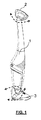
- 1 designates the body of the electric broom, connected at one end to a handle 2 and at the other end to a cleaning accessory 3.
- the handle 2 is planarly rotatable relative to the body, and the cleaning accessory 3 has a substantially triangular shape and can be tilted relative to the body.
- the handle 2 is of the closed type, is D-shaped, can rotate by 180°, and can take three fixed angular positions relative to the body (0°, + 90° and - 90°).
- the handle rotates by ⁇ 90°, thus taking two extreme positions ( Fig. 3 ) perpendicular to the central position ( Fig. 2 ), which in turn is parallel ( Fig. 2 ) to the front part of the accessory.
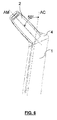
- Figures 5 and 6 show the axis of rotation AM of the handle relative to the axis of the body AC. In a non-limiting example, it is tilted by 50° towards the front part of the accessory.
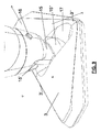
- the head 4 of the body 1 comprises an articulation including a circular joint 5 integral with the body and divided into two parts having different diameters, the upper part 5' having a greater diameter than the lower part 5".
- the joint 5 comprises two diametrically opposite stops (one of which, designated by reference numeral 7, is visible in the drawings).
- the handle 2 is fitted into the circular joint 5 in a rotatable manner.
- the underside of the handle ( Fig. 7 ) has truncated conical profiles 8 fitting into the lower part 5" of the circular joint 5, so that the handle can turn by an arc of circumference and stop against the two stops 7.
- the profiles have a shape compliant with that of the body head 4.
- control system includes a pair of opposite pins 9, the tips of which can engage into corresponding pairs of drafts.
- the pins 9 are preferably pushed by springs 10, which are internally equipped with respective guides 12 firmly positioned inside the handle, which can penetrate cavities in the pins 9, so that the pins can slide relative to the guides.
- the cleaning accessory 3 As far as the cleaning accessory 3 is concerned, it has a substantially triangular shape and is hinged, but not rotatable, relative to the axis of the body. For this purpose ( Fig. 9 ), it is connected to the body of the electric broom through a cardan joint 15.
- the latter has one end 15' connected to a pin 16 arranged in the terminal region of the body 1, and an opposite end 15" connected to a pin (not shown in the drawing) arranged in a cavity 17 in the cleaning accessory 3.
- the two pins are orthogonal to each other and lie at different heights relative to the body: the pin of the end 15" allows the electric broom to tilt forwards/backwards relative to the accessory, while the pin 15' allows the electric broom to be tilted laterally relative to the accessory.
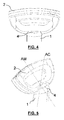
- the triangular shape of the cleaning accessory 3 is such that it has two opposite suction parts, one (at the front relative to the body) arranged at the straight front part 3', and the other arranged at the vertex 3" opposite to the straight part of the accessory.
- the suction flow can thus be distributed between the two parts, i.e. the straight part and the opposite vertex part, so that the latter can easily reach angular areas which are difficult to get to.
- the two joints of the cleaning accessory and of the handle allow reversible use of the electric broom, thus providing optimum access to narrow spaces while still ensuring good manoeuvrability and mobility without sticking, thus following at best the movements of the user's arm.
- the body towards the vertex part 3" of the accessory one facilitates the use of the straight suction part
- the opposite part 3' one facilitates the use of the vertex suction part 3".
- the additional articulations of the handle 2 and of the pin 16 contribute to ensuring optimal bending and torsion conditions of the electric broom, while also facilitating the use thereof by right-handed and left-handed people.
Abstract
- said handle (2) is planarly rotatable relative to the body by means of rotation means;
- said cleaning accessory (3) has a substantially triangular shape, and is equipped with a first suction area on a first side (3') of the accessory, and a second suction area at a vertex (3") of the accessory, opposite to said first side;
- said cleaning accessory (3) is connected to the body (1) via connection means (15) adapted to create an articulation, such as to allow the body to tilt in all directions relative to the accessory.
Description
- The present invention relates to the field of suction and cleaning systems, more specifically to a reversible electric broom.
- The vacuum cleaner is a particular household appliance intended for cleaning floors and other surfaces. Its internal mechanism allows it to suck dust and other particles mixed with air, and to hold them inside its body by means of a filter element, so as to release clean air.
- The motor, which is typically an electric one, allows sucking external air by creating a sort of a vacuum, by means of a fan, inside the vacuum cleaner.
- The electric broom is a particular type of vacuum cleaner, the body of which is typically directly connected to the cleaning accessory through a joint. In addition, the electric broom known in the art is fitted with a handle rigidly connected to the body.
- Said known electric broom suffers from some effectiveness problems when operating in narrow spaces, to which it can hardly, or not at all, gain access. In such situations, manoeuvrability and mobility are poor or even prevented and the cleaning accessory may easily get stuck, in addition to making it difficult for the user to move his/her arm.
- It is therefore the object of the present invention to propose an electric broom which can overcome the above-mentioned problems.
- The invention relates to an electric broom comprising a handle, a body and a cleaning accessory, the handle and the cleaning accessory being irremovably connected to opposite ends of the body, characterized in that:
- said handle is planarly rotatable relative to the body by means of rotation means;
- said cleaning accessory has a substantially triangular shape, and is equipped with a first suction area on a first side of the accessory, and a second suction area at a vertex of the accessory, opposite to said first side;
- said cleaning accessory is connected to the body via connection means adapted to create an articulation, such as to allow the body to tilt in all directions relative to the accessory.
- In particular, the present invention relates to an electric broom as set out in detail in the claims, which are an integral part of the present description.
- Further objects and advantages of the present invention will become apparent from the following detailed description of a preferred embodiment (and variants) thereof and from the annexed drawings, which are only supplied by way of non-limiting example, wherein:
-
Figures 1 ,2 and 3 are side views of an electric broom according to the present invention; -
Figures 4 and 5 are two side views of the handle of the electric broom; -
Figure 6 shows a further side view of the electric broom, in particular of the upper part of the body with the handle; -
Figure 7 is a sectional view of the handle, highlighting the internal components thereof; -
Figure 8 is an enlarged view of the end of the body of the electric broom, to which the handle is connected; -
Figure 9 is an enlarged view of the cleaning accessory and of its connection to the broom body. - In the drawings, the same reference numerals and letters identify the same items or components.
- With reference to the drawings, 1 designates the body of the electric broom, connected at one end to a
handle 2 and at the other end to acleaning accessory 3. - According to the main aspects of the invention, the
handle 2 is planarly rotatable relative to the body, and thecleaning accessory 3 has a substantially triangular shape and can be tilted relative to the body. - More particularly, the
handle 2 is of the closed type, is D-shaped, can rotate by 180°, and can take three fixed angular positions relative to the body (0°, + 90° and - 90°). - Preferably, the handle rotates by ± 90°, thus taking two extreme positions (
Fig. 3 ) perpendicular to the central position (Fig. 2 ), which in turn is parallel (Fig. 2 ) to the front part of the accessory. -
Figures 5 and6 show the axis of rotation AM of the handle relative to the axis of the body AC. In a non-limiting example, it is tilted by 50° towards the front part of the accessory. - With particular reference to
Figures 7 and8 , thehead 4 of thebody 1 comprises an articulation including acircular joint 5 integral with the body and divided into two parts having different diameters, the upper part 5' having a greater diameter than thelower part 5". On the circumference of the upper part there are two pairs ofrecessed drafts 6', 6", 6"', 6"" positioned at a mutual distance of 90°. In its lower part, thejoint 5 comprises two diametrically opposite stops (one of which, designated by reference numeral 7, is visible in the drawings). - The
handle 2 is fitted into thecircular joint 5 in a rotatable manner. For this purpose, the underside of the handle (Fig. 7 ) has truncatedconical profiles 8 fitting into thelower part 5" of thecircular joint 5, so that the handle can turn by an arc of circumference and stop against the two stops 7. The profiles have a shape compliant with that of thebody head 4. - In the lower internal part of the handle there is a handle rotation control system that causes the handle to stop at one of the pairs of
drafts 6', 6", 6"', 6"". - To this end, the control system includes a pair of
opposite pins 9, the tips of which can engage into corresponding pairs of drafts. - The
pins 9 are preferably pushed bysprings 10, which are internally equipped withrespective guides 12 firmly positioned inside the handle, which can penetrate cavities in thepins 9, so that the pins can slide relative to the guides. - One end of the springs engages against
stops 11 on the pins themselves, while the other end of the springs engages againststops 13 within the handle. In this manner, when the handle is turned the springs will contract and thepins 9 will move back, sliding on the edge of the upper part 5' of thecircular joint 5 and then stopping into a pair of drafts. - As far as the
cleaning accessory 3 is concerned, it has a substantially triangular shape and is hinged, but not rotatable, relative to the axis of the body. For this purpose (Fig. 9 ), it is connected to the body of the electric broom through acardan joint 15. The latter has one end 15' connected to apin 16 arranged in the terminal region of thebody 1, and anopposite end 15" connected to a pin (not shown in the drawing) arranged in acavity 17 in thecleaning accessory 3. - The two pins are orthogonal to each other and lie at different heights relative to the body: the pin of the
end 15" allows the electric broom to tilt forwards/backwards relative to the accessory, while the pin 15' allows the electric broom to be tilted laterally relative to the accessory. - The triangular shape of the
cleaning accessory 3 is such that it has two opposite suction parts, one (at the front relative to the body) arranged at the straight front part 3', and the other arranged at thevertex 3" opposite to the straight part of the accessory. The suction flow can thus be distributed between the two parts, i.e. the straight part and the opposite vertex part, so that the latter can easily reach angular areas which are difficult to get to. - Combined together, the two joints of the cleaning accessory and of the handle allow reversible use of the electric broom, thus providing optimum access to narrow spaces while still ensuring good manoeuvrability and mobility without sticking, thus following at best the movements of the user's arm. In fact, by tilting the body towards the
vertex part 3" of the accessory one facilitates the use of the straight suction part, whereas by tilting it towards the opposite part 3' one facilitates the use of thevertex suction part 3". The additional articulations of thehandle 2 and of thepin 16 contribute to ensuring optimal bending and torsion conditions of the electric broom, while also facilitating the use thereof by right-handed and left-handed people. - The above-described example of embodiment may be subject to variations without departing from the protection scope of the present invention, including all equivalent designs known to a man skilled in the art.
- The elements and features shown in the various preferred embodiments may be combined together without however departing from the protection scope of the present invention.
- From the above description, those skilled in the art will be able to produce the object of the invention without introducing any further construction details.
Claims (6)
- Electric broom comprising a handle (2), a body (1) and a cleaning accessory (3), the handle and the cleaning accessory being irremovably connected to opposite ends of the body, characterized in that:- said handle (2) is planarly rotatable relative to the body by means of rotation means;- said cleaning accessory (3) has a substantially triangular shape, and is equipped with a first suction area on a first side (3') of the accessory, and a second suction area at a vertex (3") of the accessory, opposite to said first side;- said cleaning accessory (3) is connected to the body (1) via connection means (15) adapted to create an articulation, such as to allow the body to tilt in all directions relative to the accessory.
- Electric broom according to claim 1, wherein said rotation means are adapted to rotate the handle by 180°, so that it can take three fixed angular positions relative to the body, preferably 0°, + 90° and - 90°.
- Electric broom according to claim 1 or 2, wherein said rotation means comprise:- a circular joint (5) integral with the body, two pairs of recessed drafts (6', 6", 6"', 6"") being present on the circumference of said joint, positioned at a mutual distance of 90°;- a pair of opposite pins (9) in the lower internal part of the handle, said pair of opposite pins ending with a tip adapted to engage with corresponding pairs of said drafts;- thrust means in said lower internal part of the handle, adapted to push said pair of pins towards the circumference of the joint.
- Electric broom according to claim 3, wherein said thrust means comprise:- a pair of springs (10) adapted to push said pair of pins towards the circumference of the joint;- a pair of guides (12) for said springs, firmly positioned inside said handle, said pair of pins being equipped with cavities allowing said guides to fit therein at least partially.
- Electric broom according to claim 1 or 2, wherein said rotation means comprise:- two stops (7) in diametrically opposite positions on said circumference of the circular joint (5);- profiles (8) of the underside of the handle, adapted to stop against said two stops (7), so as to define said 180° rotation of the handle.
- Electric broom according to claim 1, wherein said connection means (15) for connecting the cleaning accessory (3) to the body (1) are configured as a cardan joint comprising:- a first end (15') connected to a pin (16) arranged in the terminal region of the body, so as to allow the body to tilt relative to the accessory about a first axis of rotation;- a second end (15") connected to a cavity in said cleaning accessory, so as to allow the body to tilt relative to the accessory about a second axis of rotation orthogonal to said first axis of rotation, wherein said second axis of rotation is substantially parallel to said first side (3') of the accessory, said first and second axes of rotation lying at different heights relative to the body.
Applications Claiming Priority (1)
| Application Number | Priority Date | Filing Date | Title |
|---|---|---|---|
| ITTO20140724 | 2014-09-15 |
Publications (1)
| Publication Number | Publication Date |
|---|---|
| EP2995233A1 true EP2995233A1 (en) | 2016-03-16 |
Family
ID=51904154
Family Applications (1)
| Application Number | Title | Priority Date | Filing Date |
|---|---|---|---|
| EP15183102.1A Withdrawn EP2995233A1 (en) | 2014-09-15 | 2015-08-31 | Reversible electric broom |
Country Status (2)
| Country | Link |
|---|---|
| EP (1) | EP2995233A1 (en) |
| CN (1) | CN105411485A (en) |
Cited By (1)
| Publication number | Priority date | Publication date | Assignee | Title |
|---|---|---|---|---|
| CN111317398A (en) * | 2018-12-17 | 2020-06-23 | 无锡睿米信息技术有限公司 | Dust collector |
Families Citing this family (1)
| Publication number | Priority date | Publication date | Assignee | Title |
|---|---|---|---|---|
| EP3687278A4 (en) * | 2017-09-27 | 2020-08-26 | Changzhou Globe Co., Ltd. | Impact protecting member for a cutting tool |
Citations (6)
| Publication number | Priority date | Publication date | Assignee | Title |
|---|---|---|---|---|
| EP1321086A2 (en) * | 2001-12-21 | 2003-06-25 | NEXT-AT S.r.l. | Brush accessory for electrical appliances, particularly vacuum cleaners, electric brooms and the like provided with a suction tube |
| WO2004103144A1 (en) * | 2003-05-20 | 2004-12-02 | De' Longhi Spa | Multifunctional electric cleaning apparatus |
| WO2005034706A2 (en) * | 2003-10-09 | 2005-04-21 | T.P.A. Impex S.P.A. | Sucking device |
| DE102007040951A1 (en) * | 2007-08-30 | 2009-03-05 | Miele & Cie. Kg | Vacuum cleaner for cleaning long-pile carpet, has pressure sensor arranged at retainer and fluidically connected with suction pipe by hose that includes mouth area provided in suction pipe |
| EP2581016A1 (en) * | 2010-06-14 | 2013-04-17 | Panasonic Corporation | Upright type floor treatment device |
| WO2014091392A1 (en) * | 2012-12-10 | 2014-06-19 | Indesit Company S.P.A. | Electric broom equipped comprising a handle |
-
2015
- 2015-08-31 EP EP15183102.1A patent/EP2995233A1/en not_active Withdrawn
- 2015-09-15 CN CN201510586251.7A patent/CN105411485A/en active Pending
Patent Citations (6)
| Publication number | Priority date | Publication date | Assignee | Title |
|---|---|---|---|---|
| EP1321086A2 (en) * | 2001-12-21 | 2003-06-25 | NEXT-AT S.r.l. | Brush accessory for electrical appliances, particularly vacuum cleaners, electric brooms and the like provided with a suction tube |
| WO2004103144A1 (en) * | 2003-05-20 | 2004-12-02 | De' Longhi Spa | Multifunctional electric cleaning apparatus |
| WO2005034706A2 (en) * | 2003-10-09 | 2005-04-21 | T.P.A. Impex S.P.A. | Sucking device |
| DE102007040951A1 (en) * | 2007-08-30 | 2009-03-05 | Miele & Cie. Kg | Vacuum cleaner for cleaning long-pile carpet, has pressure sensor arranged at retainer and fluidically connected with suction pipe by hose that includes mouth area provided in suction pipe |
| EP2581016A1 (en) * | 2010-06-14 | 2013-04-17 | Panasonic Corporation | Upright type floor treatment device |
| WO2014091392A1 (en) * | 2012-12-10 | 2014-06-19 | Indesit Company S.P.A. | Electric broom equipped comprising a handle |
Cited By (1)
| Publication number | Priority date | Publication date | Assignee | Title |
|---|---|---|---|---|
| CN111317398A (en) * | 2018-12-17 | 2020-06-23 | 无锡睿米信息技术有限公司 | Dust collector |
Also Published As
| Publication number | Publication date |
|---|---|
| CN105411485A (en) | 2016-03-23 |
Similar Documents
| Publication | Publication Date | Title |
|---|---|---|
| CN110720856B (en) | Vacuum cleaning device with collapsible wand to provide storage configuration | |
| CN109715018B (en) | Cleaning head for a vacuum cleaner | |
| EP3393323B1 (en) | Improved vacuum head attachment and vacuum cleaner | |
| US9826870B2 (en) | Robotic vacuum cleaner | |
| RU2701221C2 (en) | Mop vacuum cleaner with pivotally installed suction nozzle | |
| EP2995233A1 (en) | Reversible electric broom | |
| JP2016036427A (en) | Suction tool and vacuum cleaner using the same | |
| US20200315414A1 (en) | Floor tool unit, surface treating appliance and vacuum cleaner | |
| CN108113578B (en) | Dust collector handle and dust collector | |
| US11678779B2 (en) | Vacuum cleaner accessory | |
| KR101455477B1 (en) | Electric cleaner | |
| EP2928351B1 (en) | A vacuum cleaner handle with a system for coupling a hose | |
| JP2016036426A (en) | Suction tool and vacuum cleaner using the same | |
| JP6572426B2 (en) | Suction tool and electric vacuum cleaner using the same | |
| EP3272262B1 (en) | Multifunctional nozzle | |
| US9241603B1 (en) | Swivel assembly for connecting a wand to a vacuum accessory and associated accessory tool for use on hard surface | |
| JP2005161100A (en) | Suction tool for vacuum cleaner and vacuum cleaner | |
| CN109431375B (en) | Ultrathin floor brush and dust collector | |
| JP2005211674A (en) | Suction device for electric vacuum cleaner and electric vacuum cleaner | |
| JP2013031559A (en) | Suction tool for vacuum cleaner | |
| JP2011255056A5 (en) |
Legal Events
| Date | Code | Title | Description |
|---|---|---|---|
| PUAI | Public reference made under article 153(3) epc to a published international application that has entered the european phase |
Free format text: ORIGINAL CODE: 0009012 |
|
| AK | Designated contracting states |
Kind code of ref document: A1 Designated state(s): AL AT BE BG CH CY CZ DE DK EE ES FI FR GB GR HR HU IE IS IT LI LT LU LV MC MK MT NL NO PL PT RO RS SE SI SK SM TR |
|
| AX | Request for extension of the european patent |
Extension state: BA ME |
|
| 17P | Request for examination filed |
Effective date: 20160908 |
|
| RBV | Designated contracting states (corrected) |
Designated state(s): AL AT BE BG CH CY CZ DE DK EE ES FI FR GB GR HR HU IE IS IT LI LT LU LV MC MK MT NL NO PL PT RO RS SE SI SK SM TR |
|
| RAP1 | Party data changed (applicant data changed or rights of an application transferred) |
Owner name: WHIRLPOOL EMEA S.P.A |
|
| STAA | Information on the status of an ep patent application or granted ep patent |
Free format text: STATUS: REQUEST FOR EXAMINATION WAS MADE |
|
| STAA | Information on the status of an ep patent application or granted ep patent |
Free format text: STATUS: THE APPLICATION IS DEEMED TO BE WITHDRAWN |
|
| 18D | Application deemed to be withdrawn |
Effective date: 20180301 |