EP2994731B1 - Telemetrische lastdose mit funkübertragung des signals - Google Patents
Telemetrische lastdose mit funkübertragung des signals Download PDFInfo
- Publication number
- EP2994731B1 EP2994731B1 EP14723402.5A EP14723402A EP2994731B1 EP 2994731 B1 EP2994731 B1 EP 2994731B1 EP 14723402 A EP14723402 A EP 14723402A EP 2994731 B1 EP2994731 B1 EP 2994731B1
- Authority
- EP
- European Patent Office
- Prior art keywords
- load cell
- telemetry
- signal
- pick
- module
- Prior art date
- Legal status (The legal status is an assumption and is not a legal conclusion. Google has not performed a legal analysis and makes no representation as to the accuracy of the status listed.)
- Active
Links
Images


Classifications
-
- G—PHYSICS
- G01—MEASURING; TESTING
- G01L—MEASURING FORCE, STRESS, TORQUE, WORK, MECHANICAL POWER, MECHANICAL EFFICIENCY, OR FLUID PRESSURE
- G01L5/00—Apparatus for, or methods of, measuring force, work, mechanical power, or torque, specially adapted for specific purposes
- G01L5/0061—Force sensors associated with industrial machines or actuators
- G01L5/0076—Force sensors associated with manufacturing machines
-
- G—PHYSICS
- G01—MEASURING; TESTING
- G01L—MEASURING FORCE, STRESS, TORQUE, WORK, MECHANICAL POWER, MECHANICAL EFFICIENCY, OR FLUID PRESSURE
- G01L5/00—Apparatus for, or methods of, measuring force, work, mechanical power, or torque, specially adapted for specific purposes
- G01L5/12—Apparatus for, or methods of, measuring force, work, mechanical power, or torque, specially adapted for specific purposes for measuring axial thrust in a rotary shaft, e.g. of propulsion plants
Definitions
- the present invention relates to a telemetric load cell with radio transmission of the signal according to the introductory part of the independent claim.
- the measurement of the injection force is becoming increasingly important. Especially with fully electric injection molding machines with mechanical drive, the injection force measurement is not only essential but absolutely necessary.
- strain gauges with strain gauges are attached in the power flow behind the screw. Since the worm not only moves axially, but also rotates, it can not be measured directly behind the worm because of the required connection cables - which would wind up during rotation.
- the injection force signal used for control purposes as close to the screw would have the best pressure curve for controlling the complex process of melt processing and the simultaneous injection process, because frictional forces between the nozzle and the measuring point the injection force measurement on fully electric injection molding machines usually membrane Load boxes are used, which have 4 or 8 bonded strain gauges.
- cylindrical compression load cans can also be used cylindrical compression load cans.
- indirectly measuring sensors are applied to the structure, which measure the deformations and strains of the structure caused by the injection force. These strains are often proportional to the injection force.
- Such a load box is described in Swiss patent application no. 01062/09 ( CH 701 412 B1 ).
- the CH 702 580 A2 is already a telemetric load cell for electrically measuring negative and positive injection forces become known on injection molding machines, which is mounted directly behind the rotating screw.
- the integrated amplifier and the strain gages are inductively fed and the force signal is transmitted wirelessly.
- the inductive feed takes place in the axial direction via an air gap which runs at right angles to the longitudinal center axis of the screw.
- such feeding presupposes that the drive of the worm takes place via a laterally arranged motor and via a gear transmission.
- EP 2 103 379 A1 is a chuck-integrated force measuring system for determining cutting forces on the cutting edge of a rotatable tool with at least one sensor, known.
- the sensor is a strain sensor that can be placed on a tool holder of a machine tool.
- the sensor is integrated in a measuring hub, which can be used as an adapter piece in the chuck of the machine tool.
- a stationary induction coil surrounds the rotating measuring hub for the inductive coupling of electrical energy for an integrated transmitter for the transmission of measuring signals.
- the aim of the invention is to avoid these disadvantages. According to the invention this is achieved with telemetric load cells with radio transmission of the signal of the type mentioned by the features of independent claim 1.
- the inventive design can measure the injection force as well as the torsional force with the same load box. This opens up new possibilities for controlling the injection process on injection molding machines.
- the inventive telemetric load boxes with radio transmission of the signal consist essentially of the load can body and the radially arranged feed module and the pick-up ring, the feed module containing the primary coil and the pick-up ring, the secondary coil of the inductive coupling.
- the load can body is preferably designed as Kompressiohslastdose because of the achievable high linearity, but can also be a rotating diaphragm load box or accept any other embodiment.
- the load can body rotates with the injection screw, and the strain gauges (strain gauges) mounted on the load can body are fed by inductive transmission through the feed module, as well as the separate strain gages for force and torsion measurement.
- the load cell force signals and the torsion signals are wirelessly transmitted to the receiving modules via radio. This makes it possible to continuously measure the injection force and the torsion signal simultaneously with an easily standardizable element directly on the screw.
- the load box according to the invention comprises a directly behind the screw attachable and rotatable together with this load can body which strain gauge, at least one amplifier and at least one radio module.
- the amplifier and the radio module can be fed via a secondary coil assigned to the load can body and a primary coil fixed relative to the load can body by means of inductively coupled oscillating circuits.
- the injection force signal can be transmitted by means of the radio module to a receiving module.
- the load can body has a pick-up ring containing the secondary coil and a feed module which can be attached radially above the pick-up ring contains the primary coil.
- the pick-up ring can be fixed for example by screwing or gluing. It may be U-shaped in cross-section and, for example, consist of two halves.
- the load can body can be coupled directly between the worm and the drive shaft of a motor. Lateral gear transmissions are no longer necessary, which simplifies the construction considerably.
- the signal transmission does not take place via radio, but by means of amplitude modulation via the supply module, as in the CH 702 580 A2 described. Prerequisite is the maintenance of the correct gap width. The remaining structural features remain unchanged.
- the load can body has both first strain gauges for measuring axial forces, and second strain gauges for measuring torsional forces on the worm. This significantly increases the functionality of the telemetric load cell, allowing better control of the injection molding process.
- Separate radio modules are assigned to the first and second strain gauges, their signals being simultaneously transferable to separate receiving modules. With this circuit is a complete monitoring of axial compressive forces and torsional forces possible. In certain cases, however, the signals could also be transmitted alternately with only a single radio module and only one receiving module.
- the feed module with the primary coil may have a part-circular surface which corresponds to the outer circumference of the pick-up ring and which encloses an angle between 45 ° and 180 °.
- the part-circular surface has a radius whose center ideally coincides with the longitudinal central axis of the screw or the pick-up ring.
- the distance between the pick-up ring and the feed module or the intermediate air gap can preferably be varied between 0.5 mm and 12 mm. The aim is, of course, the smallest possible air gap to ensure optimum energy transfer.
- the supply module is preferably connected via a flexible cable with an induction electronics for generating a high-frequency induction signal. In certain cases, however, this induction electronics could also be permanently assigned to the supply module.
- the injection force and the torsion can be transmitted simultaneously with the radio modules with antennas and with reception modules.
- the radial and axial strain gauges are assigned separate amplifiers and radio modules.
- the telemetric load cell may be a compression load cell, a membrane load box or a thrust load box.
- the functioning Such load boxes is known in the art and therefore will not be further described here.
- the load can body has a shank portion with a bore, in which the at least one amplifier and the at least one radio module are attached.
- the arrangement in a bore ensures that the rotating load can body has the smallest possible imbalance.
- the electrical connection to the pick-up ring and to the outside arranged strain gauges can be done via a radial bore.
- coupling sections adjoin on both sides of the shaft section with respect to the longitudinal central axis.
- These integrally formed with the shaft portion coupling portions have coupling means for coupling the screw on one side and for coupling drive parts on the other side.
- These coupling means are preferably a splined shaft and / or a splined hub.
- An injection molding machine with a telemetric load box described above has a rotary drivable screw, which is mounted in an axially movable injection unit.
- the load can body is arranged directly behind the screw and the feed module is mounted at a distance radially above the pick-up ring on the injection unit. In this way, it is ensured that the pick-up ring and feed module are exactly aligned in each axial relative position of the screw.
- the receiving module can either be arranged directly on the injection unit or on a fixed component of the machine such as the machine control box.
- FIG. 1 shows that the inventive telemetric load cell with radio transmission of the signal 1 according to the only schematic representation is connected to the drive 3, that the injection force 6 of the screw 2 is supported directly and without loss of power to the telemetric load cell with radio transmission of the signal 1 and also the torsional force 7 can be transmitted to the drive 3.
- the amplifier 10 and the radio module with antenna 11 of the rotating telemetric load cell with radio transmission of the signal 1 is fed by induction via the power module 8 and the pick-up ring 9.
- the induction electronics 13 generates the high-frequency induction signal, which is conducted via the cable 14 to the power module 8.
- the energy for operating the rotating telemetric load cell with radio transmission of the signal 1 is by means of inductively coupled oscillating circuits via the feed module 8 and the pick-up Ring 9 transmitted. This allows the simple feeding of the telemetric load cell with radio transmission of the signal 1 and separate transmission of the signals via a radio module with antenna 11 to the receiving module 12.
- the receiving module 12 can in a housing 15 together with the induction electronics 13 or at any other place or on the injection unit 4 may be attached.
- the receiving module 12 can also be attached directly to the machine control box 16 of the injection molding machine.
- radio modules with antenna 11 and receiver modules with antenna 12 are available by default and can be, for example, WLAN modules (IEEE 802.11) or WPAN modules (IEEE 802.15).
- the distance between the pick-up ring 9 and feed module 8 can vary from 0.5 to 12 mm.
- the separation of the power supply and the signal transmission simplifies the construction of the telemetry system and increases its operational reliability.
- the telemetric load cell with radio transmission of the signal 1 is preferably designed for highest linearity as a compression load box, but may also be a membrane load box, a Schublastastdose or any other design.
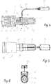
- Fig. 2 shows a cross section through the inventive telemetric load cell with radio transmission of the signal 1 with the axial DMS 17 which are glued inside in the bore 20 or externally. These axial strain gages 17 are guided on the amplifier 10.
- the amplifier 10 and the radio module 11 is fed by means of inductive coupling via the feed module 8 and the pick-up ring 9.
- the Eihspritzkraft 6 is transmitted by means of the radio module with antenna 11 to the receiving module 12 to the non-rotating injection unit 4.
- the injection force 6 can be measured.
- Fig. 3 shows a cross section through an inventive telemetric load cell with radio transmission of the signal for measurement the injection force and the torsion signal 7 at the same time.
- the torsion signal 7 is transmitted by means of the radio module with antenna 21 to the receiving module 22 on the non-rotating and only axially moving injection unit 4.
- the amplifiers 10 and 19 and the radio modules 11 and 21 are fed by means of inductive coupling via the supply module 8 and the pick-up ring 9.
- the injection force 6 and the torsion 7 are transmitted by means of a radio module with antenna 11 to the receiving module 12 to the non-rotating injection unit.
- FIGS. 4 to 6 show an alternative embodiment of a load box 1 with a load can body 28 which is formed substantially rotationally symmetrical.
- the load can body has a central shaft portion 24 with a central bore 20.
- On the outer surface of the shaft portion of the pick-up ring 9 is fixed and immediately next to it, for example, the axial strain gauges 17 are arranged. Inside the bore 20, the amplifier 10 and the radio module 11 are fixed, wherein the electrical connection to the outer shell is made via a radial bore with a small diameter.
- a coupling portion 25 in the form of a splined hub 26 and a coupling portion 25 'in the form of a spline shaft 27 are integrally arranged.
- the feed module 8 which is connected to a flexible cable 23 to the induction electronics 13, is fixed with fastening means, not shown here.
- the feed module 8 has a part-circular surface, which faces the shaft portion 24 and adapted to the radius thereof.
- the part-circular surface encloses here an angle of approx. 45 °.
- FIG. 7 shows the overall arrangement again in a perspective view, wherein the fastening means for fixing the disc-shaped feed module 8 are not shown.
- the feed module is advantageously fixed with the aid of screws in such a way that an adjustment of the air gap within a certain mass is possible.
- the connection to the induction electronics 13 is advantageously carried out via a plug connection.
- a two-piece sleeve 29 surrounds the shaft. This protects the strain gauges and at the same time absorbs the amplifier electronics.
- the pick-up ring 9 may be formed in cross-section U-shaped. For manufacturing reasons, it is advantageous if it is divided into two halves, each extending over approximately 180 °. Between the feed module 8 and the pick-up ring 9 remains an air gap x with a gap width of, for example, 0.5 to 1.5 mm. In the feed module, a likewise U-shaped counterpart 30 is fixed.
- the actual housing body of the feed module may consist of plastic material.
Landscapes
- Chemical & Material Sciences (AREA)
- Analytical Chemistry (AREA)
- Physics & Mathematics (AREA)
- General Physics & Mathematics (AREA)
- Engineering & Computer Science (AREA)
- Combustion & Propulsion (AREA)
- Injection Moulding Of Plastics Or The Like (AREA)
- Arrangements For Transmission Of Measured Signals (AREA)
Description
- Die vorliegende Erfindung bezieht sich auf eine telemetrische Lastdose mit Funkübertragung des Signals gemäss dem einleitenden Teil des unabhängigen Anspruches.
- An Kunststoff-Spritzgiessmaschinen wird die Messung der Einspritzkraft immer wichtiger. Gerade bei vollelektrischen Spritzgiessmaschinen mit mechanischem Antrieb ist die Einspritzkraftmessung nicht nur unerlässlich sondern absolut notwendig. Zur Messung dieser Kräfte werden mit Dehnungsmessstreifen beklebte Lastdosen im Kraftfluss hinter der Schnecke angebracht. Da sich die Schnecke nicht nur axial bewegt, sondern auch dreht, kann heute wegen den benötigten Anschlusskabeln - die sich bei Rotation aufwickeln würden - nicht direkt hinter der Schnecke gemessen werden. Dies obwohl das zu Regelzwecken verwendete Einspritzkraftsignal möglichst nahe an der Schnecke den besten Druckverlauf zur Regelung des komplexen Prozesses der Schmelze-Aufbereitung und des gleichzeitigen Einspritzprozesses aufweisen würde, weil Reibungskräfte zwischen der Düse und dem Messort die Einspritzkraftmessung an vollelektrisch angetriebenen Spritzgiessmaschinen in der Regel Membran-Lastdosen verwendet werden, welche 4 oder 8 geklebte Dehnungsmessstreifen aufweisen. Es können aber auch zylindrische Kompressionslastdosen zum Einsatz kommen. Oder es werden indirekt messende Sensoren auf die Struktur aufgebracht, welche die Verformungen und Dehnungen der Struktur verursacht durch die Einspritzkraft messen. Diese Dehnungen sind oft proportional zur Einspritzkraft. Eine solche Lastdose ist in der CH-Pätentanmeldung Nr.
01062/09 CH 701 412 B1 - Durch die
CH 702 580 A2 - All diesen Lastdosen ist eigen, dass für jeden Maschinentyp eine speziell dimensionierte Lastdose zu entwickeln ist, und dass das Kraftsignal nicht den besten Druckverlauf aufweist, weil sie nicht direkt hinter der Schnecke angebracht sind und somit durch Getriebe und Lagerung unerwünschte, die Messung verfälschende Reibungsverluste auftreten können.
- Ausserdem muss im Schadensfall die ganze Lastdose, welche Bestandteil der Produktionsmaschine ist, ausgewechselt werden. Dies dauert in der Regel sehr lange und die Maschine kann in dieser Zeit nicht produzieren.
- Durch die
EP 2 103 379 A1 ist ein spannfutter-integriertes Kraftmesssystem zur Bestimmung von Schneidkräften an der Werkzeugschneide eines drehbaren Werkzeugs mit zumindest einem Messaufnehmer, bekannt geworden. Der Messaufnehmer ist dabei ein Dehnungssensor, der an einer Werkzeughalterung einer Werkzeugmaschine platzierbar ist. Der Messaufnehmer ist in einer Messnabe integriert, die als ein Adapterstück in das Spannfutter der Werkzeugmaschine einsetzbar ist. Eine stationäre Induktionsspule umgibt die rotierende Messnabe zur induktiven Einkoppelung von elektrischer Energie für einen integrierten Sender zur Übertragung von Messsignalen. - Ziel der Erfindung ist es, diese Nachteile zu vermeiden. Erfindungsgemäss wird dies mit telemetrischen Lastdosen mit Funkübertragung des Signals der eingangs erwähnten Art durch die Merkmale des unabhängigen Anspruches 1 erreicht. Die erfindungsgemässe Ausführung kann mit derselben Lastdose die Einspritzkraft wie auch die Torsionskraft messen. Dies eröffnet neue Möglichkeiten zur Regelung des Einspritzprozesses an Spritzgiessmaschinen. Die erfindungsgemässen telemetrischen Lastdosen mit Funkübertragung des Signals bestehen im Wesentlichen aus dem Lastdosenkörper und dem radial angeordneten Speisemodul und dem Pick-up Ring, wobei der Speisemodul die Primärspule und der Pick-up Ring die Sekundärspule der induktiven Kopplung enthalten. Der Lastdosenkörper ist wegen der damit erreichbaren hohen Linearität vorzugsweise als Kompressiohslastdose ausgeführt, kann aber auch eine drehende Membranlastdose sein oder jede andere Ausführungsform annehmen.
- Der Lastdosenkörper dreht mit der Einspritzschnecke, und die auf dem Lastdosenkörper aufgeklebten Dehnungsmessstreifen (DMS) für Kraftmessung und Torsionsmessung sowie die separaten DMS-Verstärker für Kraft- und Torsionsmessung werden durch das Speisemodul mittels induktiver Übertragung gespeist. Die Lastdosen-Kraftsignale und die Torsionssignale werden kabellos über Funk auf die Empfangsmodule übertragen. Damit ist es möglich, direkt an der Schnecke die Einspritzkraft und das Torsionssignal zeitgleich mit einem einfach standardisierbaren Element kontinuierlich zu messen.
- Die Lastdose weist erfindungsgemäss einen direkt hinter der Schnecke anbringbaren und zusammen mit dieser drehbaren Lastdosenkörper auf, welcher Dehnungsmessstreifen, wenigstens einen Verstärker und wenigstens ein Funkmodul aufweist. Dabei sind der Verstärker und das Funkmodul über eine dem Lastdosenkörper zugeordnete Sekundärspule und eine relativ zum Lastdosenkörper feststehende Primärspule mittels induktiv gekoppelten Schwingkreisen speisbar. Das Einspritzkraftsignal ist dabei mittels dem Funkmodul auf ein Empfangsmodul übertragbar. Der Lastdosenkörper weist einen die Sekundärspule enthaltenden Pick-up Ring auf und ein radial über dem Pick-up Ring anbringbares Speisemodul enthält die Primärspule. Der Pick-up Ring kann beispielsweise durch Verschrauben oder durch Kleben fixiert werden. Er kann im Querschnitt U-förmig ausgebildet sein und beispielsweise aus zwei Hälften bestehen. Ersichtlicherweise kann mit dieser Anordnung der Lastdosenkörper unmittelbar zwischen die Schnecke und die Antriebswelle eines Motors gekoppelt werden. Seitliche Zahnradgetriebe sind nicht mehr erforderlich, was die Bauweise erheblich vereinfacht.
- In bestimmten Fällen wäre es denkbar, dass die Signalübertragung nicht über Funk erfolgt, sondern mittels Amplitudenmodulation über das Speisemodul, wie in der
CH 702 580 A2 - Der Lastdosenkörper weist sowohl erste Dehnungsmessstreifen zum Messen von axialen Kräften, als auch zweite Dehnungsmessstreifen zum Messen von Torsionskräften an der Schnecke auf. Die Funktionalität der telemetrischen Lastdose wird dadurch erheblich gesteigert, sodass sich der Spritzgiessprozess besser steuern lässt. Den ersten und zweiten Dehnungsmessstreifen sind separate Funkmodule zugeordnet, wobei deren Signale gleichzeitig auf separate Empfangsmodule übertragbar sind. Mit dieser Schaltung ist eine lückenlose Überwachung von axialen Druckkräften und Torsionkräften möglich. In bestimmten Fällen könnten die Signale aber auch wechselweise mit nur einem einzigen Funkmodul und nur einem einzigen Empfangsmodul übertragen werden.
- Das Speisemodul mit der Primärspule kann eine teilkreisförmige Oberfläche aufweisen, welche mit dem Aussenumfang des Pick-up Rings korrespondiert und welche einen Winkel zwischen 45° und 180° einschliesst. Ersichtlicherweise hat dabei die teilkreisförmige Oberfläche einen Radius, dessen Zentrum idealerweise mit der Längsmittelachse der Schnecke bzw. des Pick-up Rings zusammenfällt. Der Abstand zwischen dem Pick-up Ring und dem Speisemodul bzw. der dazwischen liegende Luftspalt kann vorzugsweise zwischen 0,5 mm und 12 mm variiert werden. Angestrebt wird selbstverständlich ein möglichst geringer Luftspalt, um eine optimale Energieübertragung zu gewährleisten.
- Das Speisemodul ist vorzugsweise über ein flexibles Kabel mit einer Induktionselektronik zum Generieren eines hochfrequenten Induktionssignals verbunden. In bestimmten Fällen könnte diese Induktionselektronik aber auch fest dem Speisemodul zugeordnet sein.
- Weitere Vorteile können erzielt werden, wenn die Einspritzkraft und die Torsion mit den Funkmodulen mit Antennen und mit Empfangsmodulen gleichzeitig übertragen werden können. Dabei sind jeweils den radialen und:axialen Dehnungsmessstreifen separate Verstärker und Funkmodule zugeordnet. Es wäre alternativ allerdings auch denkbar, dass mit einem Multiplexer von einer Messbrücke zur anderen umgeschaltet wird und dass dann mit einem einzigen Verstärker beide Messbrücken gemessen werden können.
- Die telemetrische Lastdose kann eine Kompressionslastdose, eine Membranlastdose oder eine Schublastdose sein. Die Funktionsweise derartiger Lastdosen ist dem Fachmann bekannt und wird daher hier nicht weiter beschrieben.
- Weitere Vorteile können erzielt werden, wenn der Lastdosenkörper einen Schaftabschnitt mit einer Bohrung aufweist, in welcher der wenigstens eine Verstärker und das wenigstens eine Funkmodul befestigt sind. Auf dem Aussenmantel des Schaftabschnitts ist der Pick-up Ring befestigt, beispielsweise durch Kleben oder Verschrauben. Durch die Anordnung in einer Bohrung wird erreicht, dass der sich drehende Lastdosenkörper eine möglichst geringe Unwucht aufweist. Die elektrische Verbindung zum Pick-up Ring und zu den aussen angeordneten Dehnungsmessstreifen kann über eine radiale Bohrung erfolgen.
- Besonders vorteilhaft schliessen sich bezogen auf die Längsmittelachse auf beiden Seiten des Schaftabschnitts Kupplungsabschnitte an. Diese einstückig mit dem Schaftabschnitt ausgebildeten Kupplungsabschnitte weisen Kupplungsmittel auf zum Ankuppeln der Schnecke auf der einen Seite und zum Ankuppeln von Antriebsteilen auf der anderen Seite. Bei diesen Kupplungsmitteln handelt es sich vorzugsweise um eine Keilwelle und/oder um eine Keilnabe.
- Eine Spritzgiessmaschine mit einer vorstehend beschriebenen telemetrischen Lastdose weist eine drehantreibbare Schnecke auf, welche in einer axial bewegbaren Einspritzeinheit gelagert ist. Dabei ist der Lastdosenkörper direkt hinter der Schnecke angeordnet und das Speisemodul ist im Abstand radial über dem Pick-up Ring an der Einspritzeinheit befestigt. Auf diese Weise ist gewährleistet, dass Pick-up Ring und Speisemodul in jeder axialen Relativlage der Schnecke exakt aufeinander ausgerichtet sind.
- Das Empfangsmodul kann dabei entweder unmittelbar an der Einspritzeinheit angeordnet sein oder auch an einem ortsfesten Bauteil der Maschine wie beispielsweise am Maschinensteuerungskasten.
- Keine bisher bekannten Lastdosen können all diese vorteilhaften Eigenschaften in sich vereinen, vor allem war die gleichzeitige Messung und Übermittlung der Torsions und der Einspritzkraft nicht möglich.
- Die Erfindung wird nun anhand von Zeichnungen näher erläutert. Dabei zeigt:
- Figur 1
- Eine schematische Ansicht der stark vereinfachten Einspritzeinheit einer Spritzgiessmaschine mit der Erfindungsgemässen telemetrischen Lastdose mit Funkübertragung des Signals
- Figur 2
- Einen Querschnitt durch eine Ausführungsform der erfindungsgemässen telemetrischen Lastdose mit Funkübertragung des Signals und dem Speise- und Sendemodul
- Figur 3
- Einen Querschnitt durch eine Ausführungsform einer erfindungsgemässen telemetrischen Lastdose mit Funkübertragung des Signals für axiale Einspritzkraftmessung und Torsionsmessung gleichzeitig
- Figur 4
- Einen Teilquerschnitt durch ein alternatives Ausführungsbeispiel einer Lastdose,
- Figur 5
- Eine Draufsicht auf die Lastdose gemäss
Figur 4 , - Figur 6
- Ein Schnitt durch die Ebene A-A gemäss
Figur 4 , - Figur 7
- Eine Perspektivische Darstellung einer erfindungsgemässe Lastdose, und
- Figur 8
- Einen Querschnitt durch die Pick-up-Anordnung gemäss
Figur 7 . - Gleiche Bezugszeichen bedeuten in allen Figuren gleiche Einzelheiten
- Eine erfindungsgemässe telemetrische Lastdose mit Funkübertragung des Signals 1 nach
Fig. 1 ,Fig. 2 undFig. 3 ist direkt hinter der drehenden Schnecke 2 angebracht. Die Schnecke wird über den Motor 3 rotatorisch angetrieben. Die gesamte Einspritzeinheit 4 wird mit geeigneten Mitteln entsprechend dem Einspritzvolumen des flüssigen Kunststoffes in Pfeilrichtung 5 axial vor- und rückwärts bewegt.Fig. 1 zeigt, dass die erfindungsgemässe telemetrische Lastdose mit Funkübertragung des Signals 1 gemäss der nur schematischen Darstellung so mit dem Antrieb 3 verbunden ist, dass die Einspritzkraft 6 der Schnecke 2 direkt und ohne Kraftverluste auf die telemetrische Lastdose mit Funkübertragung des Signals 1 abstützt und auch die Torsionskraft 7 auf den Antrieb 3 übertragen werden kann. Der Verstärker 10 und das Funkmodul mit Antenne 11 der drehenden telemetrischen Lastdose mit Funkübertragung des Signals 1 wird mittels Induktion über den Speisemodul 8 und den Pick-up Ring 9 gespeist. Die Induktionselektronik 13 generiert das hochfrequente Induktionssignal, welches über das Kabel 14 auf den Speisemodul 8 geleitet wird. Die Energie zum Betrieb der drehenden telemetrischen Lastdose mit Funkübertragung des Signals 1 wird mittels induktiv gekoppelten Schwingkreisen über den Speisemodul 8 und den Pick-Up Ring 9 übertragen. Dies erlaubt die einfache Speisung der telemetrischen Lastdose mit Funkübertragung des Signals 1 und separater Übertragung der Signale über einen Funkmodul mit Antenne 11 zum Empfangsmodul 12. Der Empfangsmodul 12 kann in einem Gehäuse 15 zusammen mit der Indüktionselektronik 13 oder an einem beliebigen anderen Ort an oder um die Einspritzeinheit 4 angebracht sein. Der Empfangsmodul 12 kann auch direkt am Maschinensteuerungskasten 16 der Spritzgiessmaschine angebracht werden. Solche Funkmodule mit Antenne 11 und Empfangsmodule mit Antenne 12 sind standardmässig erhältlich und können zum Beispiel WLAN-Module (IEEE 802.11) oder WPAN-Module (IEEE 802.15) sein. Der Abstand zwischen dem Pick-Up Ring 9 und Speisemodul 8 kann von 0.5 bis 12 mm variieren. Die Trennung der Energieversorgung und der Signalübertragung vereinfacht den Aufbau des Telemetriesystems und erhöht dessen Betriebssicherheit. Die telemetrische Lastdose mit Funkübertragung des Signals 1 ist vorzugsweise für höchste Linearität als Kompressionslastdose ausgeführt, kann aber auch eine Membranlastdose, eine Schublastdose oder jede andere Bauform sein. -
Fig. 2 zeigt einen Querschnitt durch die erfindungsgemässe telemetrische Lastdose mit Funkübertragung des Signals 1 mit den axialen DMS 17 welche innen in der Bohrung 20 oder aussen aufgeklebt sind. Diese axialen DMS 17 werden auf den Verstärker 10 geführt. Der Verstärker 10 und der Funkmodul 11 wird mittels induktiver Kopplung über den Speisemodul 8 und den Pick-up Ring 9 gespeist. Die Eihspritzkraft 6 wird mittels dem Funkmodul mit Antenne 11 an den Empfangsmodul 12 auf die nicht drehende Einspritzeinheit 4 übermittelt. Somit kann direkt hinter der drehenden Schnecke 2 die Einspritzkraft 6 gemessen werden. -
Fig. 3 zeigt einen Querschnitt durch eine erfindungsgemässe telemetrische Lastdose mit Funkübertragung des Signals zur Messung der Einspritzkraft und dem Signal der Torsion 7 gleichzeitig. Zusätzlich zu den axialen DMS 17 welche innen in der Bohrung oder aussen aufgeklebt sind, werden 45 Grad zur axialen Richtung der telemetrischen Lastdose mit Funkübertragung des Signals 1 innen in der Bohrung 20 oder aussen DMS 18 aufgeklebt, welche bei geeigneter Verschaltung im Verstärker 19 die Torsion des Einspritzprozesses messen können. Das Torsionssignal 7 wird mittels dem Funkmodul mit Antenne 21 an den Empfangsmodul 22 auf die nicht drehende und sich nur axial bewegende Einspritzeinheit 4 übermittelt. Der Verstärker 10 und 19 und die Funkmodule 11 und 21 werden mittels induktiver Kopplung über den Speisemodul 8 und den Pick-up Ring 9 gespeist. Die Einspritzkraft 6 und die Torsion 7 werden mittels eines Funkmoduls mit Antenne 11 an den Empfangsmodul 12 auf die nicht drehende Einspritzeinheit übermittelt. Somit kann direkt hinter der drehenden Schnecke 2 die Einspritzkraft 8 und zeitgleich die Torsion 7 gemessen werden. - Die
Figuren 4 bis 6 zeigen ein alternatives Ausführungsbeispiel einer Lastdose 1 mit einem Lastdosenkörper 28, der im Wesentlichen rotationssymmetrisch ausgebildet ist. Der Lastdosenkörper verfügt über einen mittleren Schaftabschnitt 24 mit einer zentralen Bohrung 20. Am Aussenmantel des Schaftabschnitts ist der Pick-up Ring 9 fixiert und unmittelbar daneben sind beispielsweise die axialen Dehnungsmessstreifen 17 angeordnet. Im Innern der Bohrung 20 sind der Verstärker 10 und das Funkmodul 11 fixiert, wobei die elektrische Verbindung zum Aussenmantel über eine radiale Bohrung mit geringem Durchmesser hergestellt wird. - Auf beiden Seiten des Schaftabschnitts 24 ist einstückig ein Kupplungsabschnitt 25 in der Form einer Keilnabe 26 und ein Kupplungsabschnitt 25' in der Form einer Keilwelle 27 angeordnet.
- Unmittelbar über dem Pick-up Ring 9 ist mit hier nicht näher dargestellten Befestigungsmitteln das Speisemodul 8 fixiert, das mit einem flexiblen Kabel 23 mit der Induktionselektronik 13 verbunden ist. Wie insbesondere aus
Figur 5 ersichtlich ist, verfügt das Speisemodul 8 über eine teilkreisförmige Oberfläche, welche dem Schaftabschnitt 24 zugewandt und an dessen Radius angepasst ist. Die teilkreisförmige Oberfläche schliesst hier einen Winkel von ca. 45° ein. -
Figur 7 zeigt die Gesamtanordnung nochmals in perspektivischer Darstellung, wobei die Befestigungsmittel zum Befestigen des scheibenförmigen Speisemoduls 8 nicht dargestellt sind. Das Speisemodul wird vorteilhaft mit Hilfe von Schrauben fixiert und zwar derart, dass eine Anpassung des Luftspalts innerhalb eines bestimmten Masses möglich ist. Der Anschluss an die Induktionselektronik 13 erfolgt vorteilhaft über eine Steckverbindung. Unmittelbar neben dem Pick-up Ring 9 umgibt eine zweiteilige Manschette 29 die Welle. Diese schützt die Dehnungsmessstreifen und sie nimmt gleichzeitig die Verstärkerelektronik auf. - Wie in
Figur 8 dargestellt, kann der Pick-up Ring 9 im Querschnitt U-förmig ausgebildet sein. Aus fabrikationstechnischen Gründen ist es vorteilhaft, wenn er in zwei Hälften aufgeteilt ist, die sich über je ca. 180° erstrecken. Zwischen dem Speisemodul 8 und dem Pick-up Ring 9 verbleibt ein Luftspalt x mit einer Spaltbreite von beispielsweise 0,5 bis 1,5 mm. Im Speisemodul ist ein ebenfalls U-förmiges Gegenstück 30 fixiert. Der eigentliche Gehäusekörper des Speisemoduls kann aus Kunststoffmaterial bestehen.
Claims (14)
- Telemetrische Lastdose, mit Funkübertragung des Signals zum elektrischen Messen negativer und positiver Einspritzkräfte an Spritzgiessmaschinen mit einer drehantreibbaren Schnecke (2),- wobei die Lastdose (1) einen direkt hinter der Schnecke anbringbaren und zusammen mit dieser drehbaren Lastdosenkörper (28) aufweist,- welcher Dehnungsmessstreifen (17, 18), einen Verstärker (10) und ein Funkmodul (11) aufweist,- und wobei der Verstärker und das Funkmodul über eine dem Lastdosenkörper zugeordnete Sekundärspule und eine relativ zum Lastdosenkörper feststehende Primärspule mittels induktiv gekoppelten Schwingkreisen speisbar sind,- und das Einspritzkraftsignal (6) mittels dem Funkmodul (11) auf ein Empfangsmodul (12) übertragbar ist,dadurch gekennzeichnet,- dass der Lastdosenkörper (28) einen die Sekundärspule enthaltenden Pick-up Ring (9) aufweist,- dass ein in einem Abstand radial über dem Pick-up Ring anbringbares Speisemodul (8) die Primärspule enthält, und dass der Lastdosenkörper (28) sowohl erste Dehnungsmessstreifen (17) zum Messen von axialen Kräften, als auch zweite Dehnungsmessstreifen (18) zum Messen von Torsionskräften an der Schnecke aufweist, wobei den ersten und zweiten Dehnungsmessstreifen (17, 18) separate Funkmodule (11, 21) zugeordnet sind, wobei deren Signale gleichzeitig auf separate Empfangsmodule (12, 22) übertragbar sind.
- Telemetrische Lastdose nach Anspruch 1 , dadurch gekennzeichnet, dass das Speisemodul (8) mit der Primärspule eine teilkreisförmige Oberfläche aufweist, welche mit dem Aussenumfang des Pick-up Rings (9) korrespondiert und welche einen Winkel zwischen 45° und 180° einschliesst.
- Telemetrische Lastdose nach einem der Ansprüche 1 oder 2, dadurch gekennzeichnet, dass der Abstand zwischen dem Pick-up Ring (9) und dem Speisemodul (8) zwischen 0,5 mm und 12 mm variierbar ist.
- Telemetrische Lastdose nach einem der Ansprüche 1 bis 3, dadurch gekennzeichnet, dass das Speisemodul (8) über ein Kabel (23) mit einer Induktionselektronik (13) zum Generieren eines Induktionssignals verbunden ist.
- Telemetrische Lastdose nach einem der Ansprüche 1 bis 4, dadurch gekennzeichnet, dass die telemetrische Lastdose mit Funkübertragung des Signals eine Kompressionslastdose ist.
- Telemetrische Lastdose nach einem der Ansprüche 1 bis 4, dadurch gekennzeichnet, dass die telemetrische Lastdose mit Funkübertragung des Signals eine Membranlastdose ist.
- Telemetrische Lastdose nach einem der Ansprüche 1 bis 4, dadurch gekennzeichnet, dass die telemetrische Lastdose mit Funkübertragung des Signals eine Schublastdose ist.
- Telemetrische Lastdose nach einem der Ansprüche 1 bis 7, dadurch gekennzeichnet, dass mit einem oder mit mehreren radial angeordneten Schwingkreisen (8, 9) ein oder mehrere Verstärker (10, 19) und Funkmodule (11, 21) auf der drehenden telemetrischen Lastdose (1) mit Funkübertragung des Signals betrieben werden können.
- Telemetrische Lastdose nach einem der Ansprüche 1 bis 8, dadurch gekennzeichnet, dass der Lastdosenkörper (28) einen Schaftabschnitt (24) mit einer Bohrung (20) aufweist, in welcher der Verstärker (10) und das Funkmodul (11) befestigt sind und dass auf dem Aussenmantel des Schaftabschnitts der Pick-up Ring (9) befestigt ist.
- Telemetrische Lastdose nach Anspruch 9, dadurch gekennzeichnet, dass bezogen auf die Längsmittelachse auf beiden Seite des Schaftabschnitts (24) Kupplungsabschnitte (25, 25') mit Kupplungsmitteln (26, 27) zum Ankuppeln der Schnecke auf der einen Seite und zum Ankuppeln von Antriebsteilen auf der anderen Seite angeordnet sind.
- Telemetrische Lastdose nach einem der Ansprüche 9 oder 10, dadurch gekennzeichnet, dass der Pick-up Ring (9) auf dem Aussenmantel des Schaftabschnitts (24) durch Kleben oder Verschrauben befestigt ist.
- Spritzgiessmaschine mit einer telemetrischen Lastdose nach einem der Ansprüche 1 bis 11 mit einer drehantreibbaren Schnecke (2) welche in einer axial bewegbaren Einspritzeinheit (4) gelagert ist, wobei der Lastdosenkörper (28) direkt hinter der Schnecke angeordnet ist und wobei das Speisemodul (8) im Abstand radial über dem Pick-up Ring (9) an der Einspritzeinheit (4) befestigt ist.
- Spritzgiessmaschine nach Anspruch 12, dadurch gekennzeichnet, dass das Empfangsmodul (12) an der Einspritzeinheit angeordnet ist.
- Spritzgiessmaschine nach Anspruch 13, dadurch gekennzeichnet, dass das Empfangsmodul (12) an einem Maschinensteuerungskasten (16) angeordnet ist.
Applications Claiming Priority (2)
| Application Number | Priority Date | Filing Date | Title |
|---|---|---|---|
| CH9282013 | 2013-05-08 | ||
| PCT/EP2014/059110 WO2014180784A1 (de) | 2013-05-08 | 2014-05-05 | Telemetrische lastdose mit funkübertragung des signals |
Publications (2)
| Publication Number | Publication Date |
|---|---|
| EP2994731A1 EP2994731A1 (de) | 2016-03-16 |
| EP2994731B1 true EP2994731B1 (de) | 2017-10-11 |
Family
ID=50693657
Family Applications (1)
| Application Number | Title | Priority Date | Filing Date |
|---|---|---|---|
| EP14723402.5A Active EP2994731B1 (de) | 2013-05-08 | 2014-05-05 | Telemetrische lastdose mit funkübertragung des signals |
Country Status (3)
| Country | Link |
|---|---|
| EP (1) | EP2994731B1 (de) |
| CN (1) | CN105209874B (de) |
| WO (1) | WO2014180784A1 (de) |
Family Cites Families (4)
| Publication number | Priority date | Publication date | Assignee | Title |
|---|---|---|---|---|
| JP2007054924A (ja) * | 2005-08-26 | 2007-03-08 | Toyota Motor Corp | 工具把持力測定システムおよび工具把持力測定方法 |
| DE102008015005A1 (de) * | 2008-03-19 | 2009-09-24 | Mtu Aero Engines Gmbh | Spannfutter-integriertes Kraftmesssystem |
| CH702580B1 (de) * | 2010-01-19 | 2014-06-13 | Sensormate Ag | Telemetrische Lastdose. |
| CN201935764U (zh) * | 2010-12-29 | 2011-08-17 | 蚌埠日月仪器研究所有限公司 | 一体化螺杆泵抽油机井扭矩、载荷、转速检测传输装置 |
-
2014
- 2014-05-05 CN CN201480026039.9A patent/CN105209874B/zh active Active
- 2014-05-05 WO PCT/EP2014/059110 patent/WO2014180784A1/de active Application Filing
- 2014-05-05 EP EP14723402.5A patent/EP2994731B1/de active Active
Non-Patent Citations (1)
| Title |
|---|
| None * |
Also Published As
| Publication number | Publication date |
|---|---|
| CN105209874A (zh) | 2015-12-30 |
| EP2994731A1 (de) | 2016-03-16 |
| WO2014180784A1 (de) | 2014-11-13 |
| CN105209874B (zh) | 2018-01-23 |
Similar Documents
| Publication | Publication Date | Title |
|---|---|---|
| EP0108857B1 (de) | Kraftbetätigtes Spannfutter | |
| EP0901881B1 (de) | Werkzeug oder Werkzeughalter | |
| EP3507580B1 (de) | Drehmomentsensor mit radialelastischer momentübertragung | |
| EP2411779B1 (de) | Drehmomentsensor | |
| WO2014060326A1 (de) | Honmaschine mit kraftsensor und telemetrischer signal- und energieübertragung | |
| DE102005041500A1 (de) | Vakuumpumpe | |
| EP2843359B1 (de) | Kupplung mit einem antriebseitigen Kupplungsteil und mit einem abtriebseitigen Kupplungsteil | |
| EP2113758B1 (de) | Drehmomentsensor mit Telemetriesystem | |
| DE19828513A1 (de) | Elektrisch unterstützte Hilfskraftlenkung für Kraftfahrzeuge | |
| WO2013050010A2 (de) | Vorrichtung zum überwachen des drehzustandes einer schneidrollenanordnung einer schildvortriebsmaschine und schneidrollenanordnung für eine schildvortriebsmaschine | |
| EP3507582A1 (de) | Drehmomentsensor mit dichtungsmembran | |
| DE4025430A1 (de) | Drehschrauberkopf | |
| DE4012480A1 (de) | Messwertaufnehmer fuer eine elektromotorisch angetriebene servolenkung | |
| DE3344385A1 (de) | Beruehrungsfreie messvorrichtung fuer drehmoment und/oder drehwinkel | |
| DE102012024264A1 (de) | Drehmomentsensor | |
| EP3300229B1 (de) | Hubdrehvorrichtung | |
| DE202012012688U1 (de) | Drehdurchführung | |
| EP2994731B1 (de) | Telemetrische lastdose mit funkübertragung des signals | |
| DE3210889A1 (de) | Schraubvorrichtung | |
| WO2007031111A1 (de) | Modular aufgebaute messachse | |
| EP3003613B1 (de) | Werkzeugspannsystem | |
| EP2456594A1 (de) | Elektromechanisches fügemodul mit kraftaufnehmer | |
| DE102012015357B4 (de) | Nichtschaltbare Kupplung mit Drehmomentüberwachung | |
| EP3672765B1 (de) | Drehdurchführung für eine handhabungseinheit | |
| DE19606145B4 (de) | Vorrichtung zur Aufweitung eines Honwerkzeugs |
Legal Events
| Date | Code | Title | Description |
|---|---|---|---|
| PUAI | Public reference made under article 153(3) epc to a published international application that has entered the european phase |
Free format text: ORIGINAL CODE: 0009012 |
|
| 17P | Request for examination filed |
Effective date: 20151020 |
|
| AK | Designated contracting states |
Kind code of ref document: A1 Designated state(s): AL AT BE BG CH CY CZ DE DK EE ES FI FR GB GR HR HU IE IS IT LI LT LU LV MC MK MT NL NO PL PT RO RS SE SI SK SM TR |
|
| AX | Request for extension of the european patent |
Extension state: BA ME |
|
| DAX | Request for extension of the european patent (deleted) | ||
| 17Q | First examination report despatched |
Effective date: 20160912 |
|
| REG | Reference to a national code |
Ref country code: DE Ref legal event code: R079 Ref document number: 502014005775 Country of ref document: DE Free format text: PREVIOUS MAIN CLASS: G01L0005000000 Ipc: G01L0005120000 |
|
| GRAP | Despatch of communication of intention to grant a patent |
Free format text: ORIGINAL CODE: EPIDOSNIGR1 |
|
| RIC1 | Information provided on ipc code assigned before grant |
Ipc: G01L 5/00 20060101ALI20170502BHEP Ipc: G01L 5/12 20060101AFI20170502BHEP |
|
| INTG | Intention to grant announced |
Effective date: 20170524 |
|
| GRAS | Grant fee paid |
Free format text: ORIGINAL CODE: EPIDOSNIGR3 |
|
| GRAA | (expected) grant |
Free format text: ORIGINAL CODE: 0009210 |
|
| AK | Designated contracting states |
Kind code of ref document: B1 Designated state(s): AL AT BE BG CH CY CZ DE DK EE ES FI FR GB GR HR HU IE IS IT LI LT LU LV MC MK MT NL NO PL PT RO RS SE SI SK SM TR |
|
| REG | Reference to a national code |
Ref country code: GB Ref legal event code: FG4D Free format text: NOT ENGLISH |
|
| REG | Reference to a national code |
Ref country code: CH Ref legal event code: EP |
|
| REG | Reference to a national code |
Ref country code: IE Ref legal event code: FG4D Free format text: LANGUAGE OF EP DOCUMENT: GERMAN |
|
| REG | Reference to a national code |
Ref country code: AT Ref legal event code: REF Ref document number: 936469 Country of ref document: AT Kind code of ref document: T Effective date: 20171115 |
|
| REG | Reference to a national code |
Ref country code: DE Ref legal event code: R096 Ref document number: 502014005775 Country of ref document: DE |
|
| REG | Reference to a national code |
Ref country code: CH Ref legal event code: NV Representative=s name: HEPP WENGER RYFFEL AG, CH |
|
| REG | Reference to a national code |
Ref country code: NL Ref legal event code: MP Effective date: 20171011 |
|
| REG | Reference to a national code |
Ref country code: LT Ref legal event code: MG4D |
|
| PG25 | Lapsed in a contracting state [announced via postgrant information from national office to epo] |
Ref country code: NL Free format text: LAPSE BECAUSE OF FAILURE TO SUBMIT A TRANSLATION OF THE DESCRIPTION OR TO PAY THE FEE WITHIN THE PRESCRIBED TIME-LIMIT Effective date: 20171011 |
|
| PG25 | Lapsed in a contracting state [announced via postgrant information from national office to epo] |
Ref country code: NO Free format text: LAPSE BECAUSE OF FAILURE TO SUBMIT A TRANSLATION OF THE DESCRIPTION OR TO PAY THE FEE WITHIN THE PRESCRIBED TIME-LIMIT Effective date: 20180111 Ref country code: LT Free format text: LAPSE BECAUSE OF FAILURE TO SUBMIT A TRANSLATION OF THE DESCRIPTION OR TO PAY THE FEE WITHIN THE PRESCRIBED TIME-LIMIT Effective date: 20171011 Ref country code: FI Free format text: LAPSE BECAUSE OF FAILURE TO SUBMIT A TRANSLATION OF THE DESCRIPTION OR TO PAY THE FEE WITHIN THE PRESCRIBED TIME-LIMIT Effective date: 20171011 Ref country code: SE Free format text: LAPSE BECAUSE OF FAILURE TO SUBMIT A TRANSLATION OF THE DESCRIPTION OR TO PAY THE FEE WITHIN THE PRESCRIBED TIME-LIMIT Effective date: 20171011 Ref country code: ES Free format text: LAPSE BECAUSE OF FAILURE TO SUBMIT A TRANSLATION OF THE DESCRIPTION OR TO PAY THE FEE WITHIN THE PRESCRIBED TIME-LIMIT Effective date: 20171011 |
|
| PG25 | Lapsed in a contracting state [announced via postgrant information from national office to epo] |
Ref country code: IS Free format text: LAPSE BECAUSE OF FAILURE TO SUBMIT A TRANSLATION OF THE DESCRIPTION OR TO PAY THE FEE WITHIN THE PRESCRIBED TIME-LIMIT Effective date: 20180211 Ref country code: LV Free format text: LAPSE BECAUSE OF FAILURE TO SUBMIT A TRANSLATION OF THE DESCRIPTION OR TO PAY THE FEE WITHIN THE PRESCRIBED TIME-LIMIT Effective date: 20171011 Ref country code: RS Free format text: LAPSE BECAUSE OF FAILURE TO SUBMIT A TRANSLATION OF THE DESCRIPTION OR TO PAY THE FEE WITHIN THE PRESCRIBED TIME-LIMIT Effective date: 20171011 Ref country code: GR Free format text: LAPSE BECAUSE OF FAILURE TO SUBMIT A TRANSLATION OF THE DESCRIPTION OR TO PAY THE FEE WITHIN THE PRESCRIBED TIME-LIMIT Effective date: 20180112 Ref country code: HR Free format text: LAPSE BECAUSE OF FAILURE TO SUBMIT A TRANSLATION OF THE DESCRIPTION OR TO PAY THE FEE WITHIN THE PRESCRIBED TIME-LIMIT Effective date: 20171011 Ref country code: BG Free format text: LAPSE BECAUSE OF FAILURE TO SUBMIT A TRANSLATION OF THE DESCRIPTION OR TO PAY THE FEE WITHIN THE PRESCRIBED TIME-LIMIT Effective date: 20180111 |
|
| REG | Reference to a national code |
Ref country code: DE Ref legal event code: R097 Ref document number: 502014005775 Country of ref document: DE |
|
| PG25 | Lapsed in a contracting state [announced via postgrant information from national office to epo] |
Ref country code: DK Free format text: LAPSE BECAUSE OF FAILURE TO SUBMIT A TRANSLATION OF THE DESCRIPTION OR TO PAY THE FEE WITHIN THE PRESCRIBED TIME-LIMIT Effective date: 20171011 Ref country code: SK Free format text: LAPSE BECAUSE OF FAILURE TO SUBMIT A TRANSLATION OF THE DESCRIPTION OR TO PAY THE FEE WITHIN THE PRESCRIBED TIME-LIMIT Effective date: 20171011 Ref country code: CZ Free format text: LAPSE BECAUSE OF FAILURE TO SUBMIT A TRANSLATION OF THE DESCRIPTION OR TO PAY THE FEE WITHIN THE PRESCRIBED TIME-LIMIT Effective date: 20171011 Ref country code: EE Free format text: LAPSE BECAUSE OF FAILURE TO SUBMIT A TRANSLATION OF THE DESCRIPTION OR TO PAY THE FEE WITHIN THE PRESCRIBED TIME-LIMIT Effective date: 20171011 |
|
| PLBE | No opposition filed within time limit |
Free format text: ORIGINAL CODE: 0009261 |
|
| STAA | Information on the status of an ep patent application or granted ep patent |
Free format text: STATUS: NO OPPOSITION FILED WITHIN TIME LIMIT |
|
| PG25 | Lapsed in a contracting state [announced via postgrant information from national office to epo] |
Ref country code: PL Free format text: LAPSE BECAUSE OF FAILURE TO SUBMIT A TRANSLATION OF THE DESCRIPTION OR TO PAY THE FEE WITHIN THE PRESCRIBED TIME-LIMIT Effective date: 20171011 Ref country code: RO Free format text: LAPSE BECAUSE OF FAILURE TO SUBMIT A TRANSLATION OF THE DESCRIPTION OR TO PAY THE FEE WITHIN THE PRESCRIBED TIME-LIMIT Effective date: 20171011 Ref country code: SM Free format text: LAPSE BECAUSE OF FAILURE TO SUBMIT A TRANSLATION OF THE DESCRIPTION OR TO PAY THE FEE WITHIN THE PRESCRIBED TIME-LIMIT Effective date: 20171011 |
|
| 26N | No opposition filed |
Effective date: 20180712 |
|
| PG25 | Lapsed in a contracting state [announced via postgrant information from national office to epo] |
Ref country code: MT Free format text: LAPSE BECAUSE OF FAILURE TO SUBMIT A TRANSLATION OF THE DESCRIPTION OR TO PAY THE FEE WITHIN THE PRESCRIBED TIME-LIMIT Effective date: 20171011 |
|
| PG25 | Lapsed in a contracting state [announced via postgrant information from national office to epo] |
Ref country code: SI Free format text: LAPSE BECAUSE OF FAILURE TO SUBMIT A TRANSLATION OF THE DESCRIPTION OR TO PAY THE FEE WITHIN THE PRESCRIBED TIME-LIMIT Effective date: 20171011 |
|
| GBPC | Gb: european patent ceased through non-payment of renewal fee |
Effective date: 20180505 |
|
| REG | Reference to a national code |
Ref country code: BE Ref legal event code: MM Effective date: 20180531 |
|
| PG25 | Lapsed in a contracting state [announced via postgrant information from national office to epo] |
Ref country code: MC Free format text: LAPSE BECAUSE OF FAILURE TO SUBMIT A TRANSLATION OF THE DESCRIPTION OR TO PAY THE FEE WITHIN THE PRESCRIBED TIME-LIMIT Effective date: 20171011 |
|
| REG | Reference to a national code |
Ref country code: IE Ref legal event code: MM4A |
|
| PG25 | Lapsed in a contracting state [announced via postgrant information from national office to epo] |
Ref country code: LU Free format text: LAPSE BECAUSE OF NON-PAYMENT OF DUE FEES Effective date: 20180505 |
|
| PG25 | Lapsed in a contracting state [announced via postgrant information from national office to epo] |
Ref country code: FR Free format text: LAPSE BECAUSE OF NON-PAYMENT OF DUE FEES Effective date: 20180531 Ref country code: GB Free format text: LAPSE BECAUSE OF NON-PAYMENT OF DUE FEES Effective date: 20180505 Ref country code: IE Free format text: LAPSE BECAUSE OF NON-PAYMENT OF DUE FEES Effective date: 20180505 |
|
| PG25 | Lapsed in a contracting state [announced via postgrant information from national office to epo] |
Ref country code: BE Free format text: LAPSE BECAUSE OF NON-PAYMENT OF DUE FEES Effective date: 20180531 |
|
| PG25 | Lapsed in a contracting state [announced via postgrant information from national office to epo] |
Ref country code: TR Free format text: LAPSE BECAUSE OF FAILURE TO SUBMIT A TRANSLATION OF THE DESCRIPTION OR TO PAY THE FEE WITHIN THE PRESCRIBED TIME-LIMIT Effective date: 20171011 |
|
| PG25 | Lapsed in a contracting state [announced via postgrant information from national office to epo] |
Ref country code: PT Free format text: LAPSE BECAUSE OF FAILURE TO SUBMIT A TRANSLATION OF THE DESCRIPTION OR TO PAY THE FEE WITHIN THE PRESCRIBED TIME-LIMIT Effective date: 20171011 |
|
| PG25 | Lapsed in a contracting state [announced via postgrant information from national office to epo] |
Ref country code: HU Free format text: LAPSE BECAUSE OF FAILURE TO SUBMIT A TRANSLATION OF THE DESCRIPTION OR TO PAY THE FEE WITHIN THE PRESCRIBED TIME-LIMIT; INVALID AB INITIO Effective date: 20140505 Ref country code: CY Free format text: LAPSE BECAUSE OF FAILURE TO SUBMIT A TRANSLATION OF THE DESCRIPTION OR TO PAY THE FEE WITHIN THE PRESCRIBED TIME-LIMIT Effective date: 20171011 Ref country code: MK Free format text: LAPSE BECAUSE OF NON-PAYMENT OF DUE FEES Effective date: 20171011 |
|
| PG25 | Lapsed in a contracting state [announced via postgrant information from national office to epo] |
Ref country code: AL Free format text: LAPSE BECAUSE OF FAILURE TO SUBMIT A TRANSLATION OF THE DESCRIPTION OR TO PAY THE FEE WITHIN THE PRESCRIBED TIME-LIMIT Effective date: 20171011 |
|
| PGFP | Annual fee paid to national office [announced via postgrant information from national office to epo] |
Ref country code: IT Payment date: 20230412 Year of fee payment: 10 Ref country code: DE Payment date: 20230321 Year of fee payment: 10 |
|
| PGFP | Annual fee paid to national office [announced via postgrant information from national office to epo] |
Ref country code: AT Payment date: 20230425 Year of fee payment: 10 |
|
| PGFP | Annual fee paid to national office [announced via postgrant information from national office to epo] |
Ref country code: CH Payment date: 20230724 Year of fee payment: 10 |