EP2994577B1 - Selbsteinschaltender überschwemmungsschutz - Google Patents
Selbsteinschaltender überschwemmungsschutz Download PDFInfo
- Publication number
- EP2994577B1 EP2994577B1 EP14793977.1A EP14793977A EP2994577B1 EP 2994577 B1 EP2994577 B1 EP 2994577B1 EP 14793977 A EP14793977 A EP 14793977A EP 2994577 B1 EP2994577 B1 EP 2994577B1
- Authority
- EP
- European Patent Office
- Prior art keywords
- gate
- assembly
- sidewalls
- unit
- deck
- Prior art date
- Legal status (The legal status is an assumption and is not a legal conclusion. Google has not performed a legal analysis and makes no representation as to the accuracy of the status listed.)
- Active
Links
Images


Classifications
-
- E—FIXED CONSTRUCTIONS
- E04—BUILDING
- E04H—BUILDINGS OR LIKE STRUCTURES FOR PARTICULAR PURPOSES; SWIMMING OR SPLASH BATHS OR POOLS; MASTS; FENCING; TENTS OR CANOPIES, IN GENERAL
- E04H9/00—Buildings, groups of buildings or shelters adapted to withstand or provide protection against abnormal external influences, e.g. war-like action, earthquake or extreme climate
- E04H9/14—Buildings, groups of buildings or shelters adapted to withstand or provide protection against abnormal external influences, e.g. war-like action, earthquake or extreme climate against other dangerous influences, e.g. tornadoes, floods
- E04H9/145—Floods
-
- E—FIXED CONSTRUCTIONS
- E06—DOORS, WINDOWS, SHUTTERS, OR ROLLER BLINDS IN GENERAL; LADDERS
- E06B—FIXED OR MOVABLE CLOSURES FOR OPENINGS IN BUILDINGS, VEHICLES, FENCES OR LIKE ENCLOSURES IN GENERAL, e.g. DOORS, WINDOWS, BLINDS, GATES
- E06B9/00—Screening or protective devices for wall or similar openings, with or without operating or securing mechanisms; Closures of similar construction
- E06B9/02—Shutters, movable grilles, or other safety closing devices, e.g. against burglary
- E06B9/04—Shutters, movable grilles, or other safety closing devices, e.g. against burglary of wing type, e.g. revolving or sliding
-
- E—FIXED CONSTRUCTIONS
- E04—BUILDING
- E04B—GENERAL BUILDING CONSTRUCTIONS; WALLS, e.g. PARTITIONS; ROOFS; FLOORS; CEILINGS; INSULATION OR OTHER PROTECTION OF BUILDINGS
- E04B1/00—Constructions in general; Structures which are not restricted either to walls, e.g. partitions, or floors or ceilings or roofs
- E04B1/62—Insulation or other protection; Elements or use of specified material therefor
- E04B1/66—Sealings
-
- E—FIXED CONSTRUCTIONS
- E04—BUILDING
- E04B—GENERAL BUILDING CONSTRUCTIONS; WALLS, e.g. PARTITIONS; ROOFS; FLOORS; CEILINGS; INSULATION OR OTHER PROTECTION OF BUILDINGS
- E04B1/00—Constructions in general; Structures which are not restricted either to walls, e.g. partitions, or floors or ceilings or roofs
- E04B1/62—Insulation or other protection; Elements or use of specified material therefor
- E04B1/70—Drying or keeping dry, e.g. by air vents
- E04B1/7069—Drying or keeping dry, e.g. by air vents by ventilating
- E04B1/7076—Air vents for walls
-
- E—FIXED CONSTRUCTIONS
- E06—DOORS, WINDOWS, SHUTTERS, OR ROLLER BLINDS IN GENERAL; LADDERS
- E06B—FIXED OR MOVABLE CLOSURES FOR OPENINGS IN BUILDINGS, VEHICLES, FENCES OR LIKE ENCLOSURES IN GENERAL, e.g. DOORS, WINDOWS, BLINDS, GATES
- E06B9/00—Screening or protective devices for wall or similar openings, with or without operating or securing mechanisms; Closures of similar construction
- E06B2009/007—Flood panels
Definitions
- This invention relates to barriers for guarding against horizontal entry of floodwaters through vertical openings in buildings, especially tall ventilation openings.
- Doors and other grade level vertical openings have been guarded from entrance of water by gates that are self-actuating. See U.S. Pat. 6,623,209 , by the inventor of the invention described herein.
- These self-actuating gates should be taller when raised than the projected height of flood waters above sea level, typically taken as the height of flood waters based on 100-year storm data (a 100-year storm is defined as the storm with a 1% percent chance of occurring within a region in any one given a year).
- the exit/entrance is vulnerable to flood waters exceeding 5 feet (1.524 metres) above street level.
- the top of typical exit/entrances at street level is several feet above six feet (1.829 metres), typically ten feet (3.048 metres), so that the raised height of a self actuating flood gate of the type described in U.S. Pat.
- 6,623,209 guarding the exit/entrance would have to be at least 5 feet (1.524 metres) tall for the 100 year storm and at least 10 feet (3.048 metres) tall for complete protection from flood waters that could reach to as high as the top of the typical exit/entrances opening. Due to constraints inside or outside the exit/entrance of a building, for example, stairs climbing to the level of the exit/entrance, it may not be feasible to install a self-actuating flood gate of the type provided in U.S. Pat. 6,623,209 in part at least due to the size of the housing for the gate necessary to accommodate the height the gate would have when raised.
- Embodiments are described for preventing downward flow of substantial surface water into an underground ventilation duct communicating upwardly to a ground surface opening.
- the embodiments comprise a support having a top opening and an opening in a lower portion above a floor.
- the opening in the lower portion is for venting communication with a proximate portion of the ventilation duct.
- the support supports at least one seat and paired buoyant gate set.
- the seat is mounted perpendicularly relative to the gate and a portion of a passage-way under the seat for fluidly communicating beyond such portion to the top opening of the support and to the proximate portion of the ventilation duct.
- the buoyant gate is positioned lower than the seat and the passageway, is of sufficient size to block the passageway, and is responsive to water rising in the support by floatingly pivoting upwardly until engaging the seat, thereby blocking the passageway.
- the seat of at least one set is mounted under the top opening spaced from one of the opposing sides a horizontal distance nominally equal to a fraction applied to a length for the particular opening, the fraction having the numerator 1 and a denominator which is the sum of 1 plus the number of seat and gate sets, and the buoyant gate has a seat engagement height nominally equal to the same fraction applied to the same opening length.
- the present invention provides a self-actuating gate that overcomes these constraint limitations.
- the present invention is set out in the appended claims.
- the assembly includes a frame comprising a first sidewall and a second sidewall for mounting adjacent opposite sides of the opening to project transversely outwardly from the wall.
- the assembly further comprises a plurality of flood prevention units vertically stacked one over another inside the sidewalls. Each unit includes a deck horizontally connecting the sidewalls and a buoyant gate horizontally disposed between the sidewalls below the deck.
- the gate is disposed in a plane oriented from substantially horizontal to less than vertical in the absence of a self-actuating force, e.g., rising water.
- Each gate has an upper surface, lateral sides, and front and rear ends.
- the rear end of each gate is pivotally mounted about a horizontal axis transverse to the sidewalls by one or more pivotation members.
- Each pivotation member comprises a stationary member on a support connected to the frame and a moveable member moveably joined to the stationary member for pivotation of the gate rotationally upwardly about its horizontal axis between the sidewalls for engagement with the deck on rise of water buoyantly lifting the gate.
- a limiter limits the extent of self actuated rotation of the gate.
- the limiter comprises a seat against which the gate is halted from further rotation.
- the limiter comprises a collapsible restraint one end of which is anchored to the frame below the upper surface of said gate and the other end of which is connected to the gate.
- the restraint can be a cable, suitably of stainless steel, or can be one or more foldable arms.
- the limiter comprises a configuration of the pivotation members such that the moveable member is prevented by the stationary member from rotation past a predetermined angle.
- the gate of each of the plurality of units except a vertically lowermost unit is vertically spaced at its rear end from the rear end of the gate of a next lower unit by at least the sum of a vertical dimension of the deck and a vertical height of the maximum rise of the gate of such next lower unit about the horizontal axis on which the next lower unit can rotate upwardly.
- the assembly includes sealing lip gaskets arranged on the lateral sides and front of the gates to sealing wipe respectively the sidewalls and the deck on rise of the gate and also comprises a sealing strip gasket spanning over the pivotation members from a rearward portion of the gate.
- the deck is located at a rear portion of the sidewalls and the maximum rise of the gate is vertical or within a predetermined range of degrees from vertical wherein the lip gaskets on the front of the gate provide a seal. If less than vertical, this provides for a gate that automatically re-opens by gravity after flood waters recede. The gate can go past vertical a few degrees so long as it can still seal. This would keep the gate closed after the flood waters recede, allowing workers to clear the area visually before lowering the gates to re-open a protected vent.
- the deck is located at a rear portion of the sidewalls, the maximum rise of the gate is vertical, and the stationary member includes horizontally spaced vertical flat top stands mounting between them a proximal portion of the moveable member on a fulcrum pin carried in the horizontal axis by the stands, and the moveable member distally past the stands has outwardly stepped flat shoulders to engage the flat tops of the stands and prevent further rotation when the moveable member is rotated to vertical about the axis.
- the gate of each of the plurality of units except a vertically lowermost unit is vertically spaced at its rear end from the rear end of the gate of a next lower unit by at least the sum of a vertical dimension of the deck and a distance between the front and rear ends of the next lower gate.
- a depth of a unit is substantially the same as a height of the unit. In an embodiment, all units have the same depth and height.
- the frame also comprises a horizontal box tray under each gate and, except for the lowermost unit, above the deck of the next lower unit of the assembly.
- the tray stiffens the supporting structure for the gate and deck of each unit of the assembly.
- the tray includes a plurality of apertures for vertical passage of water.
- the units above the lowermost unit further include a plurality of bars in and suitably connected to the trays under the gates to hold the gates off the trays.
- the deck is located at a rear portion of the sidewalls and at corners connecting to the sidewalls arcuately blends into the sidewalls and the front and its lateral ends of the gates arcuately meet for mating acceptance inside the arcuate corners of the deck.
- a meshwork covers the frame distal to the opening to prevent access to the flood prevention structure while allowing ventilation though the assembly when the gates are not raised.
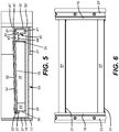
- a pair of shallow self-actuating flood barrier assemblies 10, 12 covers a lower extent of a pair of tall vertical louvered ventilation openings 11, 13 in a wall 14 of a building 15.
- a meshwork 16 covers the front of the assemblies to prevent access to the flood barrier structure behind the meshwork while allowing ventilation though the assembly to and from the ventilation openings in the absence of a flooding event.
- the assemblies of the embodiments of Fig. 1 comprise a frame 17 including a first sidewall 18 and a second sidewall 19 for mounting adjacent opposites sides of the openings 11, 13.
- openings 11, 13 are vertical and sidewalls 18, 19 are vertical and parallel to each other.
- Sidewalls 18, 19 project transversely outwardly from wall 14, as shown in Fig. 1 .
- Frame 17 further includes a top cross member 20 and a bottom cross member 21 each connected to sidewalls 18, 19 at respectively the top and bottom extents of the sidewalls.
- Bottom cross member 21 and sidewalls 18, 19 include external flanges respectively 22, 23, 24 having holes 25 for bolts 26 for bolting the assembly to wall 14 over the lower extent of openings 11, 13.
- top cross member 20 provides a brace 20a against wall member 14 and an additional flange 22a connected to frame 17 back braces frame 17 of assembly 10 against a wall support 14a.
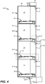
- an assembly embodiment of the invention includes a plurality of flood prevention units 27, 28, 29 and 30 vertically stacked one over another inside sidewalls 18, 19.
- Unit 28 is stacked over unit 27
- unit 29 is stacked over unit 28
- unit 30 is stacked over unit 29.
- Each unit 27, 28, 29 and 30 includes a deck 31 located at a rear portion of sidewalls 18, 19 that horizontally spans across a rear portion of the sidewalls and is connected to the sidewalls at corners at the rear of a unit 27, 28, 29 or 30.
- deck 31 is a band horizontally connected to sidewalls 18, 19 at radiused corners 32, 33 arcuately blended into the sidewalls.
- deck 31 may be an inverted U shaped band 31 butt joined to sidewalls 18, 19.
- Figs 2-5 and 10-13 show a vertical line at the forward extend of band 31. This indicates the forward extent of deck band 31 whether a butt joint or a blend joinder to sidewalls 18, 19.
- Each unit 27, 28, 29 and 30 further comprises buoyant gate 34 horizontally disposed between sidewalls 18, 19 below deck 31.
- the gate comprises buoyant material, for example, it may comprise a plurality of sealed tubes arranged side by side (a sealed tube is shown in the section views of the drawings), or a honeycomb core structure sealingly arranged between two rigid panels.
- gate 34 is oriented in a substantially horizontal plane in the absence of a self-actuating force.
- Gate 34 has an upper surface 35, lateral sides 36, 37 and front and rear ends, respectively 38, 39.
- rear end 39 of each gate 34 is pivotally mounted about a horizontal axis transverse to sidewalls 18, 19 by one or more pivotation members 40.
- Each pivotation member 40 comprises a stationary member 41 on a support 42 connected to frame 17 and a moveable member 43 connected to the rear end 39 of gate 34 by flange 44 fastened to gate 34.
- Moveable member 43 is moveably joined to stationary member 41 for pivotation of gate 34 rotationally upwardly about its horizontal axis between sidewalls 18, 19 for engagement to the front end 38 with deck 31 on rise of water buoyantly lifting the gate.
- a limiter for limiting the extent of self actuated rotation of the gate is a configuration of the stationary and moveable members of the pivotation members; stationary member 41 includes horizontally spaced vertical flat top stands 45, 46 mounting between them a proximal portion 47 of moveable member 43 on a fulcrum pin 48 carried in the horizontal axis between stands 45, 46.
- Moveable member 43 has outwardly stepped flat shoulders 49, 50 distally past stands 45, 46 to engage the flat tops of stands 45, 46 and prevent further rotation of gate 34 when moveable member 43 is rotated to vertical about the horizontal axis in which pin 44 is carried.
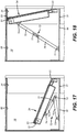
- Figs 14 and 15 show another embodiment of a limiter for limiting the extent of self actuated rotation of the gate.
- the limiter comprises tabs 70, 71 inset into radiused corners 32, 33 of deck 31 providing a seat against which gate 34 is halted from further rotation, as seen in Fig. 15 .
- Fig. 16 shows another embodiment of a limiter for limiting the extent of self actuated rotation of the gate.
- the limiter comprises at least one foldable arm 72 one end of 73 which is pivotably anchored to the frame (tray 55, see below) below gate 34 and the other end 74 of which is pivotally connected to the underside of gate 34.
- Arm 75 comprises an upper part 75 and a lower part 76.
- Upper part 75 has a slotted portion 77 that slidingly pivots on a pin 78.
- gate 34 buoys upwardly unfolding arm 72 and limiting the travel of gate 34 upward when arm 72 is fully extended.
- Fig. 17 shows another embodiment of a limiter for limiting the extent of self actuated rotation of the gate.
- the limiter comprises at least one foldable arm 72 one end of 73 which is pivotably anchored to the frame (tray 55, see below) below gate 34 and the other end 74 of which is pivotally connected to the underside of gate 34.
- Arm 75 comprises an upper part 75 and a
- arm 72 may be arranged such that the maximum rise of gate 34 is not quite vertical but is within or within a predetermined range of degrees less than vertical where the lip gaskets 51, 53 on the front of gate 34 provide a seal with desk 31. This provides for a gate that automatically re-opens by gravity after flood waters recede.
- the front end 38 and the lateral sides 36, 37 of a gate 34 arcuately meet at corners 65, 66 for mating acceptance inside the arcuately radiused corners 32, 33 of deck 31.
- Sealing lip gaskets 51 and 52 arranged respectively on front end 38 and the lateral sides 36, 37 of the gates 34 supplemented by front end lip gasket 53 sealing wipe sidewalls 18, 19 (gasket 52) and deck 31 (gaskets 51 and 53) on rise of gate 34.
- Gaskets 51-53 are attached to the upper surface 35 at front end 38 and the lateral sides 36, 37 of gate 34 by fastener strips 54.
- frame 17 of units 27, 28, 29 and 30 further comprises a horizontal tray 55 under gate 34, and in the case of all but the lowermost unit 27, above deck 31 of the next lower unit of the assembly.
- tray 55 of unit 28 is above deck 31 of the next lower unit 27
- tray 55 of unit 29 is above deck 31 of the next lower unit 28
- tray 55 of unit 30 is above deck 31 of the next lower unit 29.
- Tray 55 comprises a floor plate 56, a front plate 57 and a back plate 58. Back plate 58 and front plate 57 are laterally joined to frame 17.
- Tray 55 stiffens the structure of each unit and includes a plurality of apertures 59 in floor plate 56 for vertical passage of water, either percolating upwardly from below on rise of water above the next lower unit before rising water exceeds the height of front plate 57, or in the case of units 28-30 above the lowermost unit, draining downward to the next lower unit, and in the case of the lowermost unit 27, draining the lowermost unit of the assembly.
- Units 27-30 suitably further include a plurality of bars 60 in the trays, suitably fixed in place, under the gates to support the gates above floor plate 56 so water can freely percolate upward under the gates to buoyant rotationally lift the gates 34 up out of the trays.
- a tray is not necessary as gate 34 may be maintained at rest in a plane oriented from substantially horizontal to less than vertical in the absence of a self-actuating force by horizontal rods connecting to sidewalls 18, 19 positioned at a level supporting the gates from below in a plane from substantially horizontal to less than vertical. Rising water will buoyantly and hydrostatically raise the gates as the water climbs under the gates. Either embodiments that do or do not have stiffening trays are within the scope of the invention.
- a sealing strip gasket 61 spans over pivotation members 41, 43 from rear end 39 of gate 34 for sealing against flow under rear end 39 of gate 34.
- a sealing strip 61 seals against water penetration between tray 55 and rear end 39 of a gate 34.
- a sealing strip 61 seals against water penetration between rear end 39 of a gate 34 and the deck 31 of the next lower unit except in the case of unit 27, where sealing is between the rear end 39 of gate 34 and frame 17.
- Gates 34 of each of the plurality of units 28, 29, 30 above the vertically lowermost unit 27 are vertically spaced at their rear end 39 from the rear end 39 of the gate of a next lower unit by at least the sum of a vertical dimension of a horizontal portion of the deck 31 and a distance between the front and rear ends 38, 39 of the next lower gate 34.
- rear end 39 of gate 34 of unit 28 is so spaced from rear end 39 of gate 34 of unit 27;
- rear end 39 of gate 34 of unit 29 is so spaced from rear end 39 of gate 34 of unit 28;
- rear end 39 of gate 34 of unit 30 is so spaced from rear end 39 of gate 34 of unit 29.
- all units 27, 28, 29 and 30 have the same depth and height.
- depth is the distance from frame back 62 to the frame front 63 which contains meshwork 16. In embodiments with trays 55, this is close to the dimension from back plate 58 to front plate 57 of tray 55. Height is the distance from the floor plate 56 of a unit to the floor plate 56 of the next higher unit.
- the units are substantially square in side elevation or vertical section (front to back) as, for example, seen in Fig. 4 .
- the distance separating the top 64 of front plate 57 of a tray 55 to the bottom of the deck 31 of the same unit is the ventilation window through which air passes when a gate 34 is not self-activated by rising water
- FIG. 10 the operation of the embodiments of Figs. 1-8 is depicted.
- gate 34 of lowermost flood prevention unit 27 of self-actuating flood barrier assembly 10 buoyantly lifting gate 34 rotationally upwardly between sidewalls 18, 19 about the horizontal axis defined by fulcrum pin 48 of pivotation members 40, 43.
- As gate 34 rises water is prevented from escaping past gate 34 into opening 13 by lateral lip seals 52 sealingly wiping sidewalls 18, 19 and by strip gasket 61 sealing between rear end 39 of gate 34 and back plate 58 of tray 55.
- the hydrostatic pressure of the water pressing against the underside of the gate increases and contributes more and more to pushing against the underside of the gate as at the same time smaller and smaller moments of the gravity forces are acting against the upper surface of the gate and more and more moments of the gravitational force are borne by the pivotation members.
- the hydrostatic pressure of water pressing against the underside of the gate surpasses the buoyancy forces and overcomes the gravitational forces, and the gate is pushed to its final upright position at vertical or within a predetermined range of degrees from vertical wherein the lip gaskets on the front of the gate still provide a seal.
- gravity forces are parallel to the underside of the gate and normal to the pivotation axis.
- the buoyancy forces are parallel to the underside of the gate, essentially normal to the pivotation axis and opposing the gravitational force. Hydrostatic pressure normal to the underside of the gate holds the gate upright
- FIG. 11 gate 34 of unit 27 has risen further on rise of water driven more by hydrostatic pressure pressing against the underside of gate 34 and has been swept across deck 31 with front end lip seal 51 and supplemental front end seal 53 sealingly engaging deck 31.
- Gate 34 has been prevented from rotating past vertical by seating of square shoulders 49, 50 of moveable member 43 on flat top stands 45, 46 of stationary member 41. Further rise of water is depicted in Figs. 11 and 12 in which the function described for unit 27 is repeated in unit 28, and also for unit 29, and in Fig. 13 , wherein all units 26-30 are self- activated, erect and guarding opening 13.
- Figs. 14-18 show alternative embodiments for limiting the extent of rise of gate 34.
- a self-actuating flood barrier assembly unconstrained from installation by grade level structures and responsive to rising water for preventing entrance of flood waters though an opening in a wall.
- the assembly is mountable directly onto the protected wall.
- the assembly provides sequential operation of a plurality of higher and higher gates rather than one very tall gate, and provides a shallow unobtrusive profile on the exterior of a protected opening. Because the assembly permits air flow though it under normal non-flooding conditions, the assembly is especially useful for protecting ventilation openings where air passage through the opening is necessary under normal non-flooding conditions, and further, for ventilation openings, allows at least some ventilation to continue until the uppermost gate has fully closed.
- a method of guarding an opening for example a ventilation opening, in a wall of a structure against entrance of floodwaters while maintaining ventilation during non-flooding conditions, comprising mounting a frame comprising a first sidewall and a parallel second sidewall adjacent opposite sides of the opening to project transversely outwardly from the wall, the frame supporting a plurality of flood prevention units vertically stacked one over another inside the sidewalls, each unit comprising (a) a deck connecting the sidewalls, and (b) a buoyant gate horizontally disposed between the sidewalls below the deck in a plane oriented from substantially horizontal to less than vertical in the absence of a self-actuating force, such gate having an upper surface, lateral sides, and front and rear ends, the rear end of each gate being pivotally mounted about a horizontal axis transverse to the sidewalls by one or more pivotation members, each the pivotation members comprising a stationary member on a frame support and a moveable member moveably joined to the stationary member for pivotation of the
Landscapes
- Engineering & Computer Science (AREA)
- Architecture (AREA)
- Structural Engineering (AREA)
- Civil Engineering (AREA)
- Physics & Mathematics (AREA)
- Electromagnetism (AREA)
- Business, Economics & Management (AREA)
- Emergency Management (AREA)
- Environmental & Geological Engineering (AREA)
- Barrages (AREA)
- Revetment (AREA)
Claims (14)
- Flache, selbsttätige Hochwasserbarrierenbaugruppe (10), die auf steigendes Wasser reagiert, um den Eintritt von Hochwasser durch eine horizontale Öffnung (11) in einer aufrechten Wand (14) einer Struktur (15) zu verhindern, die Folgendes umfasst:a) einen Rahmen (17), der eine erste aufrechte Seitenwand (18) und eine zweite aufrechte Seitenwand (19) für eine Montage neben gegenüberliegenden Seiten der genannten Öffnung umfasst, um von der genannten Wand transversal nach außen vorzustehen,b) eine Mehrzahl von Hochwasserschutzeinheiten (27, 28, 29, 30), die innerhalb der genannten Seitenwände vertikal übereinandergestapelt sind, wobei jede Einheit Folgendes umfasst:dadurch gekennzeichnet, dass eine Dichtung (51, 53) am vorderen Ende jedes Tores (34) angeordnet ist, um das genannte Deck (31) der Einheit beim Ansteigen des genannten Tores dichtend abzuwischen.i) ein Deck (31), das die genannten Seitenwände horizontal verbindet, ein Deck für jede Einheit,ii) ein schwimmfähiges Tor (34), das horizontal zwischen den genannten Seitenwänden und unterhalb des genannten Decks der Einheit in einer Ebene angeordnet ist, die von im Wesentlichen horizontal bis zu weniger als vertikal orientiert ist, wenn keine selbsttätige Kraft vorhanden ist, wobei das Tor eine Oberseite (35), laterale Seiten (36, 37) sowie ein vorderes und ein hinteres Ende (38, 39) hat, wobei das hintere Ende jedes Tores schwenkbar um eine horizontale Achse transversal zu den genannten Seitenwänden über ein oder mehrere Schwenkelemente (40) befestigt ist, wobei jedes genannte Schwenkelement ein stationäres Element (41) auf einem mit dem genannten Rahmen verbundenen Träger (42) und ein bewegliches Element (43) umfasst, das beweglich mit dem genannten stationären Element verbunden ist, um das Tor um seine horizontale Achse zwischen den genannten Seitenwänden drehend nach oben zu schwenken, so dass es mit dem genannten Deck in Eingriff kommt, wenn ansteigendes Wasser das Tor schwimmend anhebt,iii) einen Begrenzer zum Begrenzen des Ausmaßes der selbsttätigen Drehung des genannten Tores, wobei das Tor von jeder aus der genannten Mehrzahl von Einheiten, mit Ausnahme der vertikal untersten Einheit, an seinem hinteren Ende vertikal vom hinteren Ende des Tores einer nächstunteren Einheit um wenigstens die Summe der vertikalen Dickenabmessung des genannten Decks und einer vertikalen Höhe des maximalen Anstiegs des Tores einer solchen nächstunteren Einheit um die horizontale Achse beabstandet ist, auf der sich die genannte nächstuntere Einheit nach oben drehen kann,
- Baugruppe nach Anspruch 1, die ferner Dichtungen (52), die an den lateralen Seiten der Tore angeordnet sind, um die genannten Seitenwände beim Ansteigen der genannten Tore dichtend abzuwischen, und außerdem ein Dichtungsband (61) umfasst, das die genannten Schwenkelemente von einem rückwärtigen Abschnitt von jedem der Tore aus überspannt.
- Baugruppe nach Anspruch 1, wobei sich das genannte Deck an einem hinteren Abschnitt der Seitenwände befindet und wobei der maximale Anstieg der genannten Tore die Vertikale ist oder innerhalb eines vorbestimmten Gradbereichs von der Vertikalen liegt.
- Baugruppe nach Anspruch 1, wobei die genannten Hochwasserschutzeinheiten, die innerhalb der genannten Seitenwände vertikal übereinandergestapelt sind, in einer solchen Ausrichtung gestapelt sind, dass eine oberste Einheit und evtl. Zwischeneinheiten vollständig über einer untersten Einheit liegen.
- Baugruppe nach Anspruch 1, wobei der genannte Begrenzer Folgendes umfasst: einen Sitz (70, 71), an dem eine weitere Drehung des genannten Tors gestoppt wird; oder eine zusammenklappbare Haltevorrichtung (72), von der ein Ende (73) an dem genannten Rahmen unterhalb der genannten Oberseite des genannten Tores verankert und das andere Ende (74) mit dem genannten Tor verbunden ist; oder eine Konfiguration der Schwenkelemente, so dass das bewegliche Element durch das stationäre Element an einer Drehung um einen vorbestimmten Winkel hinaus gehindert wird.
- Baugruppe nach Anspruch 3, wobei die genannten Schwenkelemente so konfiguriert sind, dass das genannte bewegliche Element durch das genannte stationäre Element an einer Drehung um einen vorbestimmten Winkel hinaus gehindert wird.
- Baugruppe nach Anspruch 6, wobei das genannte stationäre Element horizontal beabstandete vertikale Ständer mit flacher Oberseite (45, 46) beinhaltet, zwischen denen ein proximaler Abschnitt (47) des genannten beweglichen Elements auf einem Drehbolzen (48) montiert ist, der in der genannten horizontalen Achse zwischen den genannten Ständern getragen wird, und wobei das genannte bewegliche Element distal an den genannten Ständern vorbei nach außen abgestufte flache Schultern (49, 50) hat, um mit der genannten flachen Oberseite der genannten Ständer in Eingriff zu kommen und eine weitere Drehung zu verhindern, wenn das bewegliche Element um die genannte Achse in die Vertikale gedreht wird.
- Baugruppe nach Anspruch 1, wobei eine Tiefe von wenigstens einer der Einheiten im Wesentlichen gleich einer Höhe dieser ein oder mehreren Einheiten ist.
- Baugruppe nach einem der vorherigen Ansprüche, wobei der genannte Rahmen ferner mehrere Schalen (55), eine für jede Einheit, unter dem Tor seiner Einheit und, mit Ausnahme der untersten Einheit, über dem Deck der nächstunteren Einheit der Baugruppe umfasst, wobei die genannten Schalen jeweils einen horizontalen Boden (56) und eine aufrechte Vorderseite (57) und Rückplatten (58) umfassen, die vom Boden aufsteigen.
- Baugruppe nach Anspruch 9, wobei jede Schale mehrere Löcher (59) für den vertikalen Durchfluss von Wasser beinhaltet.
- Baugruppe nach Anspruch 9, wobei die genannten Einheiten ferner mehrere horizontale Stangen (60) beinhalten, die mit den Schalen unter den Toren verbunden sind, um die Tore von den Schalen weg zu tragen.
- Baugruppe nach einem der vorherigen Ansprüche, wobei sich jedes Deck an einem hinteren Abschnitt der Seitenwände und an mit den genannten Seitenwänden verbundenen Ecken (32, 33) befindet, wobei sich die genannten Ecken bogenförmig in die genannten Seitenwände einfügen und wobei sich das genannte vordere Ende und die lateralen Seiten der genannten Tore für eine passende Aufnahme innerhalb der genannten bogenförmigen Ecken des Decks bogenförmig treffen.
- Baugruppe nach einem der vorherigen Ansprüche, wobei der genannte Rahmen ferner ein oberes Querelement (20) und ein unteres Querelement (21) beinhaltet, die jeweils mit den genannten Seitenwänden an den oberen bzw. den unteren Ausdehnungen der Seitenwände verbunden sind, und wobei wenigstens das genannte untere Querelement und die genannten Seitenwände einen äußeren Flansch (22, 23, 24) mit Löchern für Schraubbolzen zum Verschrauben der Baugruppe mit der genannten Wand über der genannten Öffnung beinhalten.
- Baugruppe nach Anspruch 13, die ferner ein Geflecht (16) umfasst, das mit dem Rahmen distal zur genannten Öffnung verbunden ist, um den Zugang zu den genannten Hochwasserschutzeinheiten zu verhindern und gleichzeitig eine Belüftung durch die genannte Baugruppe zu ermöglichen, wenn die Tore nicht angehoben sind.
Priority Applications (1)
| Application Number | Priority Date | Filing Date | Title |
|---|---|---|---|
| PL14793977T PL2994577T3 (pl) | 2013-05-09 | 2014-05-09 | Samoczynna bariera przeciwpowodziowa |
Applications Claiming Priority (2)
| Application Number | Priority Date | Filing Date | Title |
|---|---|---|---|
| US201361821366P | 2013-05-09 | 2013-05-09 | |
| PCT/US2014/037552 WO2014183070A1 (en) | 2013-05-09 | 2014-05-09 | Self-actuating flood quard |
Publications (3)
| Publication Number | Publication Date |
|---|---|
| EP2994577A1 EP2994577A1 (de) | 2016-03-16 |
| EP2994577A4 EP2994577A4 (de) | 2017-01-25 |
| EP2994577B1 true EP2994577B1 (de) | 2020-07-08 |
Family
ID=51867780
Family Applications (1)
| Application Number | Title | Priority Date | Filing Date |
|---|---|---|---|
| EP14793977.1A Active EP2994577B1 (de) | 2013-05-09 | 2014-05-09 | Selbsteinschaltender überschwemmungsschutz |
Country Status (7)
| Country | Link |
|---|---|
| US (1) | US10072436B2 (de) |
| EP (1) | EP2994577B1 (de) |
| DK (1) | DK2994577T3 (de) |
| ES (1) | ES2815563T3 (de) |
| PL (1) | PL2994577T3 (de) |
| PT (1) | PT2994577T (de) |
| WO (1) | WO2014183070A1 (de) |
Families Citing this family (12)
| Publication number | Priority date | Publication date | Assignee | Title |
|---|---|---|---|---|
| US10435908B2 (en) | 2013-10-06 | 2019-10-08 | Floodbreak, L.L.C. | Flood protection for underground air vents |
| JP6472104B2 (ja) * | 2015-09-25 | 2019-02-20 | 溥 寺田 | 水門 |
| EP3485116B1 (de) * | 2016-07-15 | 2023-10-25 | Floodbreak, L.L.C. | Hochwasserschutz für unterirdische belüftungsöffnungen |
| US10106945B2 (en) | 2016-10-21 | 2018-10-23 | Floodbreak, L.L.C. | Flood protection for underground air vents |
| DK179294B1 (da) * | 2017-03-30 | 2018-04-16 | Steen Olsen Invest Aps | Stormflodssikring |
| US20180347265A1 (en) * | 2017-05-30 | 2018-12-06 | Carey Gerald Bolt | Apparatus for providing protection to a structure |
| CN107254865B (zh) * | 2017-06-20 | 2024-06-07 | 南京拓元机电工程有限公司 | 浮体叠加导向机构 |
| CN108374630A (zh) * | 2018-03-19 | 2018-08-07 | 西安建筑科技大学 | 一种风亭挡水通风卷帘窗 |
| CN110185009B (zh) * | 2019-06-23 | 2023-08-15 | 李孝兵 | 联动式翻倒闸 |
| CN112627364B (zh) * | 2020-12-02 | 2021-11-12 | 山东水利职业学院 | 一种面向海绵城市规划建设的建筑物防水网 |
| CN116876413B (zh) * | 2023-06-09 | 2025-12-12 | 中铁第四勘察设计院集团有限公司 | 一种防淹装置的检修装置及方法 |
| CN119491473B (zh) * | 2025-01-20 | 2025-05-06 | 安徽省(水利部淮河水利委员会)水利科学研究院(安徽省水利工程质量检测中心站) | 一种水利工程用可控流量式闸门 |
Family Cites Families (13)
| Publication number | Priority date | Publication date | Assignee | Title |
|---|---|---|---|---|
| US563133A (en) | 1896-06-30 | Paul e | ||
| US4377352A (en) * | 1981-01-02 | 1983-03-22 | Goodstein Charles B | Self-actuating water containment barrier |
| KR20030041900A (ko) * | 2002-04-03 | 2003-05-27 | 한상관 | 다단 배출 시스템의 작용에 의해 오염된 수질이자연정화되면서 어도가 자연 형성되는 자동보 수문과 그구성방법 |
| US6623209B1 (en) * | 2002-04-04 | 2003-09-23 | Floodbreak Llc | Automatic flood gate |
| US8033753B2 (en) | 2008-01-18 | 2011-10-11 | Floodbreak, L.L.C. | Automatic flooding protection for underground ventilation ducts |
| US8001735B2 (en) * | 2008-04-02 | 2011-08-23 | The Presray Corporation | Flood barrier system |
| EP2352894B9 (de) * | 2008-11-01 | 2018-02-21 | Bluewater Design Associates Limited | Lüfter |
| JP5180945B2 (ja) * | 2009-11-24 | 2013-04-10 | 日立造船株式会社 | 起伏ゲート式防波堤の係留装置 |
| JP5199227B2 (ja) * | 2009-12-15 | 2013-05-15 | 日立造船株式会社 | 波除用フラップゲートの起立状態保持機構 |
| US20120034032A1 (en) | 2010-08-05 | 2012-02-09 | Waters Jr Louis A | Self-Actuating Flood Guard |
| JP5762822B2 (ja) * | 2011-05-20 | 2015-08-12 | 日立造船株式会社 | 浮体式フラップゲート |
| JP5792022B2 (ja) * | 2011-10-19 | 2015-10-07 | 日立造船株式会社 | 壁面設置用フラップゲート式防水パネル |
| US8869455B1 (en) * | 2013-11-13 | 2014-10-28 | Azeal J. McFall | Flood gate system for doorways |
-
2014
- 2014-05-09 PL PL14793977T patent/PL2994577T3/pl unknown
- 2014-05-09 DK DK14793977.1T patent/DK2994577T3/da active
- 2014-05-09 EP EP14793977.1A patent/EP2994577B1/de active Active
- 2014-05-09 PT PT147939771T patent/PT2994577T/pt unknown
- 2014-05-09 WO PCT/US2014/037552 patent/WO2014183070A1/en not_active Ceased
- 2014-05-09 ES ES14793977T patent/ES2815563T3/es active Active
- 2014-05-09 US US14/889,036 patent/US10072436B2/en active Active
Non-Patent Citations (1)
| Title |
|---|
| None * |
Also Published As
| Publication number | Publication date |
|---|---|
| US20160076268A1 (en) | 2016-03-17 |
| EP2994577A1 (de) | 2016-03-16 |
| WO2014183070A1 (en) | 2014-11-13 |
| EP2994577A4 (de) | 2017-01-25 |
| ES2815563T3 (es) | 2021-03-30 |
| PT2994577T (pt) | 2020-09-01 |
| PL2994577T3 (pl) | 2020-12-14 |
| US10072436B2 (en) | 2018-09-11 |
| DK2994577T3 (da) | 2020-09-28 |
Similar Documents
| Publication | Publication Date | Title |
|---|---|---|
| EP2994577B1 (de) | Selbsteinschaltender überschwemmungsschutz | |
| EP2601354B1 (de) | Verfahren zur Montage eines selbsteinschaltenden Überschwemmungsschutzes | |
| US9267254B2 (en) | Flood protection system | |
| US7744310B2 (en) | Hydrostatically operated variable height bulkhead | |
| EP2257691B1 (de) | Automatischer überschwemmungsschutz für unterirdische lüftungskanäle | |
| JP5588567B2 (ja) | 自動作動式の高潮障壁 | |
| US20160097212A1 (en) | Flood protection for underground air vents | |
| KR101619162B1 (ko) | 홍수방호벽 | |
| EP3748085B1 (de) | Hochwasserbarriere | |
| AU2011249593A1 (en) | Flood protection device | |
| US7497644B1 (en) | Automatic liquid barrier system | |
| US20070237585A1 (en) | Water barrier device | |
| JP3770554B2 (ja) | 水防用のウオータゲート装置 | |
| JP5747300B1 (ja) | 溢水防止装置 | |
| KR101199472B1 (ko) | 방호벽용 방수문 | |
| GB2485557A (en) | Doorway flood protection device | |
| GB2371324A (en) | Pivotable flood barrier | |
| EP3371377B1 (de) | Selbsteinschaltender überschwemmungsschutz | |
| GB2592950A (en) | Barrier for preventing liquid entry to an area | |
| KR101230652B1 (ko) | 항만 내 육상구역에 설치되는 방호벽 방수문 | |
| ES2410589B1 (es) | Sistema de barrera autónoma contra inundación. | |
| SK7217Y1 (sk) | Ochranná protipovodňová bariéra |
Legal Events
| Date | Code | Title | Description |
|---|---|---|---|
| PUAI | Public reference made under article 153(3) epc to a published international application that has entered the european phase |
Free format text: ORIGINAL CODE: 0009012 |
|
| 17P | Request for examination filed |
Effective date: 20151208 |
|
| AK | Designated contracting states |
Kind code of ref document: A1 Designated state(s): AL AT BE BG CH CY CZ DE DK EE ES FI FR GB GR HR HU IE IS IT LI LT LU LV MC MK MT NL NO PL PT RO RS SE SI SK SM TR |
|
| AX | Request for extension of the european patent |
Extension state: BA ME |
|
| DAX | Request for extension of the european patent (deleted) | ||
| A4 | Supplementary search report drawn up and despatched |
Effective date: 20170103 |
|
| RIC1 | Information provided on ipc code assigned before grant |
Ipc: E06B 9/04 20060101ALI20161221BHEP Ipc: E04B 1/70 20060101ALI20161221BHEP Ipc: E04B 1/66 20060101ALI20161221BHEP Ipc: E02B 7/40 20060101AFI20161221BHEP Ipc: E06B 9/00 20060101ALI20161221BHEP Ipc: E02B 7/50 20060101ALI20161221BHEP Ipc: E04H 9/14 20060101ALI20161221BHEP |
|
| GRAP | Despatch of communication of intention to grant a patent |
Free format text: ORIGINAL CODE: EPIDOSNIGR1 |
|
| STAA | Information on the status of an ep patent application or granted ep patent |
Free format text: STATUS: GRANT OF PATENT IS INTENDED |
|
| INTG | Intention to grant announced |
Effective date: 20190207 |
|
| GRAJ | Information related to disapproval of communication of intention to grant by the applicant or resumption of examination proceedings by the epo deleted |
Free format text: ORIGINAL CODE: EPIDOSDIGR1 |
|
| STAA | Information on the status of an ep patent application or granted ep patent |
Free format text: STATUS: REQUEST FOR EXAMINATION WAS MADE |
|
| RAP1 | Party data changed (applicant data changed or rights of an application transferred) |
Owner name: FLOODBREAK, LLC |
|
| RIN1 | Information on inventor provided before grant (corrected) |
Inventor name: WATERS, LOUIS A., JR. |
|
| INTC | Intention to grant announced (deleted) | ||
| RAP1 | Party data changed (applicant data changed or rights of an application transferred) |
Owner name: FLOODBREAK, LLC |
|
| GRAP | Despatch of communication of intention to grant a patent |
Free format text: ORIGINAL CODE: EPIDOSNIGR1 |
|
| STAA | Information on the status of an ep patent application or granted ep patent |
Free format text: STATUS: GRANT OF PATENT IS INTENDED |
|
| INTG | Intention to grant announced |
Effective date: 20190819 |
|
| GRAJ | Information related to disapproval of communication of intention to grant by the applicant or resumption of examination proceedings by the epo deleted |
Free format text: ORIGINAL CODE: EPIDOSDIGR1 |
|
| STAA | Information on the status of an ep patent application or granted ep patent |
Free format text: STATUS: REQUEST FOR EXAMINATION WAS MADE |
|
| INTC | Intention to grant announced (deleted) | ||
| RIN1 | Information on inventor provided before grant (corrected) |
Inventor name: WATERS, LOUIS A., JR. |
|
| GRAP | Despatch of communication of intention to grant a patent |
Free format text: ORIGINAL CODE: EPIDOSNIGR1 |
|
| STAA | Information on the status of an ep patent application or granted ep patent |
Free format text: STATUS: GRANT OF PATENT IS INTENDED |
|
| RAP1 | Party data changed (applicant data changed or rights of an application transferred) |
Owner name: FLOODBREAK, LLC |
|
| INTG | Intention to grant announced |
Effective date: 20200122 |
|
| RIN1 | Information on inventor provided before grant (corrected) |
Inventor name: WATERS, LOUIS A., JR. |
|
| GRAS | Grant fee paid |
Free format text: ORIGINAL CODE: EPIDOSNIGR3 |
|
| GRAA | (expected) grant |
Free format text: ORIGINAL CODE: 0009210 |
|
| STAA | Information on the status of an ep patent application or granted ep patent |
Free format text: STATUS: THE PATENT HAS BEEN GRANTED |
|
| AK | Designated contracting states |
Kind code of ref document: B1 Designated state(s): AL AT BE BG CH CY CZ DE DK EE ES FI FR GB GR HR HU IE IS IT LI LT LU LV MC MK MT NL NO PL PT RO RS SE SI SK SM TR |
|
| REG | Reference to a national code |
Ref country code: CH Ref legal event code: EP Ref country code: AT Ref legal event code: REF Ref document number: 1288560 Country of ref document: AT Kind code of ref document: T Effective date: 20200715 |
|
| REG | Reference to a national code |
Ref country code: DE Ref legal event code: R096 Ref document number: 602014067529 Country of ref document: DE |
|
| REG | Reference to a national code |
Ref country code: IE Ref legal event code: FG4D |
|
| REG | Reference to a national code |
Ref country code: SE Ref legal event code: TRGR |
|
| REG | Reference to a national code |
Ref country code: PT Ref legal event code: SC4A Ref document number: 2994577 Country of ref document: PT Date of ref document: 20200901 Kind code of ref document: T Free format text: AVAILABILITY OF NATIONAL TRANSLATION Effective date: 20200824 |
|
| REG | Reference to a national code |
Ref country code: DK Ref legal event code: T3 Effective date: 20200923 |
|
| REG | Reference to a national code |
Ref country code: NL Ref legal event code: FP |
|
| REG | Reference to a national code |
Ref country code: LT Ref legal event code: MG4D |
|
| REG | Reference to a national code |
Ref country code: AT Ref legal event code: MK05 Ref document number: 1288560 Country of ref document: AT Kind code of ref document: T Effective date: 20200708 |
|
| PG25 | Lapsed in a contracting state [announced via postgrant information from national office to epo] |
Ref country code: BG Free format text: LAPSE BECAUSE OF FAILURE TO SUBMIT A TRANSLATION OF THE DESCRIPTION OR TO PAY THE FEE WITHIN THE PRESCRIBED TIME-LIMIT Effective date: 20201008 Ref country code: AT Free format text: LAPSE BECAUSE OF FAILURE TO SUBMIT A TRANSLATION OF THE DESCRIPTION OR TO PAY THE FEE WITHIN THE PRESCRIBED TIME-LIMIT Effective date: 20200708 Ref country code: LT Free format text: LAPSE BECAUSE OF FAILURE TO SUBMIT A TRANSLATION OF THE DESCRIPTION OR TO PAY THE FEE WITHIN THE PRESCRIBED TIME-LIMIT Effective date: 20200708 Ref country code: NO Free format text: LAPSE BECAUSE OF FAILURE TO SUBMIT A TRANSLATION OF THE DESCRIPTION OR TO PAY THE FEE WITHIN THE PRESCRIBED TIME-LIMIT Effective date: 20201008 Ref country code: GR Free format text: LAPSE BECAUSE OF FAILURE TO SUBMIT A TRANSLATION OF THE DESCRIPTION OR TO PAY THE FEE WITHIN THE PRESCRIBED TIME-LIMIT Effective date: 20201009 Ref country code: HR Free format text: LAPSE BECAUSE OF FAILURE TO SUBMIT A TRANSLATION OF THE DESCRIPTION OR TO PAY THE FEE WITHIN THE PRESCRIBED TIME-LIMIT Effective date: 20200708 Ref country code: FI Free format text: LAPSE BECAUSE OF FAILURE TO SUBMIT A TRANSLATION OF THE DESCRIPTION OR TO PAY THE FEE WITHIN THE PRESCRIBED TIME-LIMIT Effective date: 20200708 |
|
| PG25 | Lapsed in a contracting state [announced via postgrant information from national office to epo] |
Ref country code: LV Free format text: LAPSE BECAUSE OF FAILURE TO SUBMIT A TRANSLATION OF THE DESCRIPTION OR TO PAY THE FEE WITHIN THE PRESCRIBED TIME-LIMIT Effective date: 20200708 Ref country code: RS Free format text: LAPSE BECAUSE OF FAILURE TO SUBMIT A TRANSLATION OF THE DESCRIPTION OR TO PAY THE FEE WITHIN THE PRESCRIBED TIME-LIMIT Effective date: 20200708 Ref country code: IS Free format text: LAPSE BECAUSE OF FAILURE TO SUBMIT A TRANSLATION OF THE DESCRIPTION OR TO PAY THE FEE WITHIN THE PRESCRIBED TIME-LIMIT Effective date: 20201108 |
|
| REG | Reference to a national code |
Ref country code: ES Ref legal event code: FG2A Ref document number: 2815563 Country of ref document: ES Kind code of ref document: T3 Effective date: 20210330 |
|
| REG | Reference to a national code |
Ref country code: DE Ref legal event code: R097 Ref document number: 602014067529 Country of ref document: DE |
|
| PG25 | Lapsed in a contracting state [announced via postgrant information from national office to epo] |
Ref country code: RO Free format text: LAPSE BECAUSE OF FAILURE TO SUBMIT A TRANSLATION OF THE DESCRIPTION OR TO PAY THE FEE WITHIN THE PRESCRIBED TIME-LIMIT Effective date: 20200708 Ref country code: SM Free format text: LAPSE BECAUSE OF FAILURE TO SUBMIT A TRANSLATION OF THE DESCRIPTION OR TO PAY THE FEE WITHIN THE PRESCRIBED TIME-LIMIT Effective date: 20200708 Ref country code: EE Free format text: LAPSE BECAUSE OF FAILURE TO SUBMIT A TRANSLATION OF THE DESCRIPTION OR TO PAY THE FEE WITHIN THE PRESCRIBED TIME-LIMIT Effective date: 20200708 Ref country code: IT Free format text: LAPSE BECAUSE OF FAILURE TO SUBMIT A TRANSLATION OF THE DESCRIPTION OR TO PAY THE FEE WITHIN THE PRESCRIBED TIME-LIMIT Effective date: 20200708 Ref country code: CZ Free format text: LAPSE BECAUSE OF FAILURE TO SUBMIT A TRANSLATION OF THE DESCRIPTION OR TO PAY THE FEE WITHIN THE PRESCRIBED TIME-LIMIT Effective date: 20200708 |
|
| PLBE | No opposition filed within time limit |
Free format text: ORIGINAL CODE: 0009261 |
|
| STAA | Information on the status of an ep patent application or granted ep patent |
Free format text: STATUS: NO OPPOSITION FILED WITHIN TIME LIMIT |
|
| PG25 | Lapsed in a contracting state [announced via postgrant information from national office to epo] |
Ref country code: AL Free format text: LAPSE BECAUSE OF FAILURE TO SUBMIT A TRANSLATION OF THE DESCRIPTION OR TO PAY THE FEE WITHIN THE PRESCRIBED TIME-LIMIT Effective date: 20200708 |
|
| 26N | No opposition filed |
Effective date: 20210409 |
|
| PG25 | Lapsed in a contracting state [announced via postgrant information from national office to epo] |
Ref country code: SK Free format text: LAPSE BECAUSE OF FAILURE TO SUBMIT A TRANSLATION OF THE DESCRIPTION OR TO PAY THE FEE WITHIN THE PRESCRIBED TIME-LIMIT Effective date: 20200708 |
|
| PG25 | Lapsed in a contracting state [announced via postgrant information from national office to epo] |
Ref country code: SI Free format text: LAPSE BECAUSE OF FAILURE TO SUBMIT A TRANSLATION OF THE DESCRIPTION OR TO PAY THE FEE WITHIN THE PRESCRIBED TIME-LIMIT Effective date: 20200708 |
|
| REG | Reference to a national code |
Ref country code: CH Ref legal event code: PL |
|
| PG25 | Lapsed in a contracting state [announced via postgrant information from national office to epo] |
Ref country code: CH Free format text: LAPSE BECAUSE OF NON-PAYMENT OF DUE FEES Effective date: 20210531 Ref country code: LI Free format text: LAPSE BECAUSE OF NON-PAYMENT OF DUE FEES Effective date: 20210531 Ref country code: MC Free format text: LAPSE BECAUSE OF FAILURE TO SUBMIT A TRANSLATION OF THE DESCRIPTION OR TO PAY THE FEE WITHIN THE PRESCRIBED TIME-LIMIT Effective date: 20200708 Ref country code: LU Free format text: LAPSE BECAUSE OF NON-PAYMENT OF DUE FEES Effective date: 20210509 |
|
| PG25 | Lapsed in a contracting state [announced via postgrant information from national office to epo] |
Ref country code: HU Free format text: LAPSE BECAUSE OF FAILURE TO SUBMIT A TRANSLATION OF THE DESCRIPTION OR TO PAY THE FEE WITHIN THE PRESCRIBED TIME-LIMIT; INVALID AB INITIO Effective date: 20140509 |
|
| PG25 | Lapsed in a contracting state [announced via postgrant information from national office to epo] |
Ref country code: CY Free format text: LAPSE BECAUSE OF FAILURE TO SUBMIT A TRANSLATION OF THE DESCRIPTION OR TO PAY THE FEE WITHIN THE PRESCRIBED TIME-LIMIT Effective date: 20200708 |
|
| PG25 | Lapsed in a contracting state [announced via postgrant information from national office to epo] |
Ref country code: MK Free format text: LAPSE BECAUSE OF FAILURE TO SUBMIT A TRANSLATION OF THE DESCRIPTION OR TO PAY THE FEE WITHIN THE PRESCRIBED TIME-LIMIT Effective date: 20200708 |
|
| PG25 | Lapsed in a contracting state [announced via postgrant information from national office to epo] |
Ref country code: MT Free format text: LAPSE BECAUSE OF FAILURE TO SUBMIT A TRANSLATION OF THE DESCRIPTION OR TO PAY THE FEE WITHIN THE PRESCRIBED TIME-LIMIT Effective date: 20200708 |
|
| PGFP | Annual fee paid to national office [announced via postgrant information from national office to epo] |
Ref country code: NL Payment date: 20250507 Year of fee payment: 12 |
|
| PGFP | Annual fee paid to national office [announced via postgrant information from national office to epo] |
Ref country code: PL Payment date: 20250503 Year of fee payment: 12 Ref country code: DE Payment date: 20250506 Year of fee payment: 12 |
|
| PGFP | Annual fee paid to national office [announced via postgrant information from national office to epo] |
Ref country code: DK Payment date: 20250515 Year of fee payment: 12 |
|
| PGFP | Annual fee paid to national office [announced via postgrant information from national office to epo] |
Ref country code: BE Payment date: 20250507 Year of fee payment: 12 |
|
| PGFP | Annual fee paid to national office [announced via postgrant information from national office to epo] |
Ref country code: PT Payment date: 20250502 Year of fee payment: 12 |
|
| PGFP | Annual fee paid to national office [announced via postgrant information from national office to epo] |
Ref country code: FR Payment date: 20250515 Year of fee payment: 12 |
|
| PGFP | Annual fee paid to national office [announced via postgrant information from national office to epo] |
Ref country code: IE Payment date: 20250507 Year of fee payment: 12 |
|
| PGFP | Annual fee paid to national office [announced via postgrant information from national office to epo] |
Ref country code: SE Payment date: 20250506 Year of fee payment: 12 |
|
| PGFP | Annual fee paid to national office [announced via postgrant information from national office to epo] |
Ref country code: ES Payment date: 20250606 Year of fee payment: 12 |
|
| PG25 | Lapsed in a contracting state [announced via postgrant information from national office to epo] |
Ref country code: TR Free format text: LAPSE BECAUSE OF FAILURE TO SUBMIT A TRANSLATION OF THE DESCRIPTION OR TO PAY THE FEE WITHIN THE PRESCRIBED TIME-LIMIT Effective date: 20200708 |
|
| PGFP | Annual fee paid to national office [announced via postgrant information from national office to epo] |
Ref country code: GB Payment date: 20260330 Year of fee payment: 13 |