EP2994263B1 - Laser drilling method and apparatus with radiation output changes in a radial direction during drilling of a workpiece - Google Patents
Laser drilling method and apparatus with radiation output changes in a radial direction during drilling of a workpiece Download PDFInfo
- Publication number
- EP2994263B1 EP2994263B1 EP14727050.8A EP14727050A EP2994263B1 EP 2994263 B1 EP2994263 B1 EP 2994263B1 EP 14727050 A EP14727050 A EP 14727050A EP 2994263 B1 EP2994263 B1 EP 2994263B1
- Authority
- EP
- European Patent Office
- Prior art keywords
- laser beam
- hole
- laser
- scanning
- workpiece
- Prior art date
- Legal status (The legal status is an assumption and is not a legal conclusion. Google has not performed a legal analysis and makes no representation as to the accuracy of the status listed.)
- Active
Links
Images



Classifications
-
- B—PERFORMING OPERATIONS; TRANSPORTING
- B23—MACHINE TOOLS; METAL-WORKING NOT OTHERWISE PROVIDED FOR
- B23K—SOLDERING OR UNSOLDERING; WELDING; CLADDING OR PLATING BY SOLDERING OR WELDING; CUTTING BY APPLYING HEAT LOCALLY, e.g. FLAME CUTTING; WORKING BY LASER BEAM
- B23K26/00—Working by laser beam, e.g. welding, cutting or boring
- B23K26/36—Removing material
- B23K26/38—Removing material by boring or cutting
- B23K26/382—Removing material by boring or cutting by boring
- B23K26/384—Removing material by boring or cutting by boring of specially shaped holes
-
- B—PERFORMING OPERATIONS; TRANSPORTING
- B23—MACHINE TOOLS; METAL-WORKING NOT OTHERWISE PROVIDED FOR
- B23K—SOLDERING OR UNSOLDERING; WELDING; CLADDING OR PLATING BY SOLDERING OR WELDING; CUTTING BY APPLYING HEAT LOCALLY, e.g. FLAME CUTTING; WORKING BY LASER BEAM
- B23K26/00—Working by laser beam, e.g. welding, cutting or boring
- B23K26/02—Positioning or observing the workpiece, e.g. with respect to the point of impact; Aligning, aiming or focusing the laser beam
- B23K26/06—Shaping the laser beam, e.g. by masks or multi-focusing
- B23K26/062—Shaping the laser beam, e.g. by masks or multi-focusing by direct control of the laser beam
- B23K26/0622—Shaping the laser beam, e.g. by masks or multi-focusing by direct control of the laser beam by shaping pulses
-
- B—PERFORMING OPERATIONS; TRANSPORTING
- B23—MACHINE TOOLS; METAL-WORKING NOT OTHERWISE PROVIDED FOR
- B23K—SOLDERING OR UNSOLDERING; WELDING; CLADDING OR PLATING BY SOLDERING OR WELDING; CUTTING BY APPLYING HEAT LOCALLY, e.g. FLAME CUTTING; WORKING BY LASER BEAM
- B23K26/00—Working by laser beam, e.g. welding, cutting or boring
- B23K26/02—Positioning or observing the workpiece, e.g. with respect to the point of impact; Aligning, aiming or focusing the laser beam
- B23K26/06—Shaping the laser beam, e.g. by masks or multi-focusing
- B23K26/062—Shaping the laser beam, e.g. by masks or multi-focusing by direct control of the laser beam
- B23K26/0626—Energy control of the laser beam
-
- B—PERFORMING OPERATIONS; TRANSPORTING
- B23—MACHINE TOOLS; METAL-WORKING NOT OTHERWISE PROVIDED FOR
- B23K—SOLDERING OR UNSOLDERING; WELDING; CLADDING OR PLATING BY SOLDERING OR WELDING; CUTTING BY APPLYING HEAT LOCALLY, e.g. FLAME CUTTING; WORKING BY LASER BEAM
- B23K26/00—Working by laser beam, e.g. welding, cutting or boring
- B23K26/02—Positioning or observing the workpiece, e.g. with respect to the point of impact; Aligning, aiming or focusing the laser beam
- B23K26/06—Shaping the laser beam, e.g. by masks or multi-focusing
- B23K26/073—Shaping the laser spot
- B23K26/0736—Shaping the laser spot into an oval shape, e.g. elliptic shape
-
- B—PERFORMING OPERATIONS; TRANSPORTING
- B23—MACHINE TOOLS; METAL-WORKING NOT OTHERWISE PROVIDED FOR
- B23K—SOLDERING OR UNSOLDERING; WELDING; CLADDING OR PLATING BY SOLDERING OR WELDING; CUTTING BY APPLYING HEAT LOCALLY, e.g. FLAME CUTTING; WORKING BY LASER BEAM
- B23K26/00—Working by laser beam, e.g. welding, cutting or boring
- B23K26/08—Devices involving relative movement between laser beam and workpiece
- B23K26/082—Scanning systems, i.e. devices involving movement of the laser beam relative to the laser head
-
- B—PERFORMING OPERATIONS; TRANSPORTING
- B23—MACHINE TOOLS; METAL-WORKING NOT OTHERWISE PROVIDED FOR
- B23K—SOLDERING OR UNSOLDERING; WELDING; CLADDING OR PLATING BY SOLDERING OR WELDING; CUTTING BY APPLYING HEAT LOCALLY, e.g. FLAME CUTTING; WORKING BY LASER BEAM
- B23K26/00—Working by laser beam, e.g. welding, cutting or boring
- B23K26/36—Removing material
- B23K26/38—Removing material by boring or cutting
- B23K26/382—Removing material by boring or cutting by boring
-
- B—PERFORMING OPERATIONS; TRANSPORTING
- B23—MACHINE TOOLS; METAL-WORKING NOT OTHERWISE PROVIDED FOR
- B23K—SOLDERING OR UNSOLDERING; WELDING; CLADDING OR PLATING BY SOLDERING OR WELDING; CUTTING BY APPLYING HEAT LOCALLY, e.g. FLAME CUTTING; WORKING BY LASER BEAM
- B23K26/00—Working by laser beam, e.g. welding, cutting or boring
- B23K26/36—Removing material
- B23K26/38—Removing material by boring or cutting
- B23K26/382—Removing material by boring or cutting by boring
- B23K26/389—Removing material by boring or cutting by boring of fluid openings, e.g. nozzles, jets
Definitions
- the present invention relates to a laser drilling method and apparatus.
- JP 2004-243404 A describes a method for enlarging a hole while performing scanning with a laser beam.
- an inclination angle of the hole thus enlarged is 10 degrees at the maximum, and there is a possibility machining cannot be performed when a necessary inclination angle of a hole is larger than that.
- an injection port of a fuel injection valve of an injector it is necessary for an inclination angle of a hole to be 40 degrees at the maximum.
- US6070813A on which the preamble of claims 1 and 8 is based, discloses a laser drilled nozzle in a tip of a fuel injector.
- US2011298156A1 discloses laser systems and methods for scribing or dicing semiconductor devices and/or severing electrically conductive links with laser pulses having shaped temporal profiles.
- the present invention provides a laser drilling method and apparatus each of which is able to increase a degree of freedom of an inclination angle of a hole and is able to finish a surface of the hole smoothly.
- a laser drilling method is a laser drilling method for performing drilling on a workpiece by use of a laser beam as defined in claim 1, and the laser drilling method includes: scanning with the laser beam centered around a through hole toward a radial direction while changing a radiation output of the laser beam, after machining the through hole by radiating the laser beam to the workpiece.
- the radiation output of the laser beam may be changed to be smaller as the laser beam is distanced from the through hole in the radial direction.
- the radiation output of the laser beam may be changed to be smaller as the laser beam is distanced from the through hole in the radial direction.
- the laser beam may be radiated in an idling manner at a position inside a diameter of the through hole, after machining the through hole. This makes it possible to improve machining efficiency.
- a pulse energy of the laser beam, a repetition frequency of a pulse interval of a pulse of the laser beam, a scanning speed of the laser beam, and a radiation time in the scanning with the laser beam may be changed so as to change the radiation output of the laser beam.
- the laser beam may be radiated to the workpiece so that a shape of a bottom-side hole of the through hole and a shape of an upper-side hole of the through hole have different phases in a top view.
- the laser beam may be radiated to the workpiece so that a shape of the through hole is a circular shape or an elliptical shape in a top view.
- the scanning with the laser beam may be performed in a spiral manner at the time of the scanning with the laser beam centered around the through hole toward the radial direction.
- a laser drilling apparatus is a laser drilling apparatus for performing drilling on a workpiece by use of a laser as defined in claim 8, and the laser drilling apparatus includes: a control section configured to scanning with the laser beam centered around the through hole toward a radial direction while changing a radiation output of the laser beam, after machining a through hole by radiating the laser beam to the workpiece.
- a laser drilling method and apparatus each of which is able to increase a degree of freedom of an inclination angle of a hole and is able to finish a surface of the hole smoothly.
- FIG. 1 is a configuration diagram illustrating an example of a laser drilling apparatus 100 according to the present embodiment.
- the laser drilling apparatus 100 includes a laser oscillator 1, a galvanometer mirror 2, a motor 3, a galvanometer mirror 4, a motor 5, a condenser lens 6, and a control section (not shown) that drive-controls each driving section such as the laser oscillator 1 or the motor.
- the laser oscillator 1 is an ultrashort pulse laser that outputs a laser beam LA as pulsed light.
- the laser oscillator 1 outputs a picosecond laser beam as the laser beam LA.
- the galvanometer mirror 2 polarizes, in a given direction, the laser beam LA emitted from the laser oscillator 1.
- the motor 3 rotates the galvanometer mirror 2 in a given direction.
- the motor 3 is controlled to rotate so that the galvanometer mirror 2 is rotationally driven.
- the galvanometer mirror 4 polarizes, in a given direction, the laser beam LA polarized by the galvanometer mirror 2.
- the motor 5 rotates the galvanometer mirror 4 in a given direction.
- the motor 5 is controlled to rotate so that the galvanometer mirror 4 is rotationally driven.
- the condenser lens 6 condenses the laser beam LA polarized by the galvanometer mirror 4 on a surface of a workpiece 7.
- the laser beam LA is perpendicularly condensed on the surface of the workpiece 7.
- the laser drilling apparatus 100 polarizes the laser beam LA emitted from the laser oscillator 1 by the galvanometer mirror 2 and the galvanometer mirror 4, condenses the polarized laser beam LA by the condenser lens 6, and radiates the condensed laser beam LA to the workpiece 7. Accordingly, the laser drilling apparatus 100 radiates the laser beam LA emitted from the laser oscillator 1, such that the laser beam LA is aligned by the galvanometer mirrors 2, 4 at a given position in a machining region of the surface of the workpiece 7.
- the laser drilling apparatus 100 swings the galvanometer mirrors 2, 4 in respective directions shown by arrows in the figure in a reciprocating manner, so as to performing scanning with the laser beam LA on the machining region of the surface of the workpiece 7, thereby performing drilling on the workpiece 7.
- the laser drilling apparatus 100 performs scanning on the workpiece 7 with the laser beam LA so that a locus of the laser beam LA draws a desired shape.
- the lower-left view in FIG. 1 is a schematic view illustrating the locus of the laser beam LA at the time when the laser drilling apparatus 100 performs scanning with the laser beam LA.
- An example illustrated in this figure illustrates a circular scan diameter of a case where the locus of the laser beam LA has a circular shape, and an elliptical scan diameter of a case where the locus of the laser beam LA has an elliptical shape. Note that the locus of the laser beam LA is not limited to them, and the scanning may be performed so that the laser beam draws other given shapes.
- the laser drilling apparatus 100 radiates the laser beam LA to the workpiece 7 so as to machine a through hole (step S100). Subsequently, the laser drilling apparatus 100 performs scanning with the laser beam LA from the through hole toward a radial direction while changing a radiation output of the laser beam LA (step S200).
- the scanning is performed, according to the present invention, with the laser beam LA in the radial direction while the radiation output of the laser beam LA is changed, thereby making it possible to enlarge an inclination angle of the hole to a given angle.
- This makes it possible to increase a degree of freedom of the inclination angle of the hole.
- the scanning is performed with the laser beam LA in the radial direction while the radiation output of the laser beam LA is changed, it is possible to improve a surface roughness of a surface of the hole to desired accuracy. This makes it possible to finish the surface of the hole smoothly.
- the laser drilling method according to the present invention includes step 1 illustrated in the left view in the figure, and step 2 illustrated in the right view in the figure.
- Step 1 is a step of radiating the laser beam LA to the workpiece 7 so as to machine a through hole 8, and corresponds to S100 illustrated in FIG. 2 .
- Step 2 is a step of performing scanning with the laser beam LA from the formed through hole 8 toward the radial direction while changing the radiation output of the laser beam LA, and corresponds to S200 illustrated in FIG. 2 .
- the radial direction indicates a direction away from the through hole 8 formed in step 1.
- FIGS. 3B and 3C are schematic views to describe contents of the machining process in step 1 and step 2 illustrated in FIG. 3A in detail.
- FIG. 3B is a top view schematically illustrating a shape of a bottom-side hole of the through hole 8 or the locus of the laser beam LA.
- FIG. 3C is a sectional view schematically illustrating the workpiece 7 with regard to a line X-X' in FIG. 3A .
- step 1 illustrated in the left view in FIG. 3A is described with reference to the leftmost schematic view in FIG. 3B and the leftmost schematic view in FIG. 3C .
- the laser drilling apparatus 100 radiates the laser beam LA to the workpiece 7 so as to form the through hole 8 that penetrates through the workpiece 7.
- the laser drilling apparatus 100 forms the through hole 8 by performing rotational scanning with the laser beam LA in a rotating arrow direction (a circumferential direction) shown herein.
- a shape 9 of the bottom-side hole of the through hole 8 thus formed is an elliptical shape. Note that, in the leftmost schematic view in FIG. 3B , a spot of the laser beam LA in the scanning is indicated by A.
- the shape 9 of the bottom-side hole of the through hole 8 is not limited to the elliptical shape, and can be formed in a given circular shape or a given elliptical shape having a desired diameter.
- a scanning method with the laser beam LA at the time of forming the through hole 8 is not limited to the rotational scanning, and any other well-known scanning method may be employed provided that the scanning method is able to form the shape 9 of the bottom-side hole of the through hole 8 in a given circular shape or a given elliptical shape having a desired diameter.
- step 2 illustrated in the right view in FIG. 3A after the through hole 8 is formed, the laser drilling apparatus 100 performs scanning with the laser beam LA from the through hole 8 thus formed toward the radial direction while changing the radiation output of the laser beam LA, as illustrated in the figure.
- a state of the scanning with the laser beam LA and the machining of the through hole 8 at this time is described with reference to the second to fourth schematic views from the left in FIG. 3B and the second to fourth schematic views from the left in FIG. 3C .
- the laser drilling apparatus 100 performs scanning with the laser beam LA on an inner region of the shape 9 of the bottom-side hole of the through hole 8.
- the second schematic view from the left in FIG. 3B illustrates a locus 10 of the laser beam LA at this time.
- the laser drilling apparatus 100 decreases a level of the radiation output of the laser beam LA from an output level at the time of forming the through hole 8, to a predetermined output level. Note that, in the second schematic view from the left in FIG. 3B , a spot of the laser beam LA in the scanning is indicated by B.
- the scanning with the laser beam LA at this time is not limited to the rotational scanning, and the laser beam LA may be radiated to a predetermined fixed position inside a diameter of the bottom-side hole of the through hole 8.
- the laser drilling apparatus 100 radiates the laser beam LA not directly to the workpiece 7, but in an idling manner in a region inside the shape 9 of the bottom-side hole of the through hole 8.
- the laser beam LA is radiated so as to form the through hole 8 in the workpiece 7 and then the scanning with the laser beam LA is performed toward the radial direction centered around the through hole 8 thus formed, it is possible to surely prevent the laser beam LA from being radiated to the shape 9 of the bottom-side hole of the through hole 8 thus formed. Further, when the through hole 8 is formed, the laser beam LA of a high output level is used, thereby making it possible to from the through hole 8 in a short time.
- the laser drilling apparatus 100 performs scanning with the laser beam LA toward the radial direction from the through hole 8 thus formed.
- the laser drilling apparatus 100 performs rotational scanning with the laser beam LA in rotating arrow directions in the views and performs scanning the laser beam LA so as to enlarge a locus of the laser beam LA in the radial direction.
- the third and fourth schematic view from the left in FIG. 3B illustrates a locus 11 of the laser beam LA in the middle of this scanning, and the locus 11 draws a perfect circle shape.
- the fourth schematic view from the left in FIG. 3B illustrates a locus 12 of the laser beam LA at a timing when the scanning with the laser beam LA is finished, and the locus 12 draws an oblong elliptical shape.
- the elliptical shape that the locus 12 draws corresponds to a shape 13 of an upper-side hole of the through hole 8. Note that, in the third and fourth schematic views from the left in FIG. 3B , spots of the laser beam LA at the time of scanning are indicated by C, D.
- the laser drilling apparatus 100 performs the scanning from the through hole 8 toward the radial direction while rotating the laser beam LA in a circumferential direction. At this time, the laser drilling apparatus 100 radiates the laser beam LA from a center of the through hole 8 toward the radial direction in a spiral manner, for example. Note that the scanning with the laser beam is not limited to the spiral manner, and the laser beam LA may be radiated concentrically from the through hole 8 toward the radial direction.
- the laser drilling apparatus 100 decreases the level of the radiation output of the laser beam LA as a scanning diameter of the laser beam LA is distanced from the through hole 8 in the radial direction.
- the radiation output of the laser beam LA to be radiated to the workpiece 7 is changed to be smaller as the laser beam LA is distanced from the through hole 8 in the radial direction.
- a depth of the surface of the through hole 8 to be scraped off by the laser beam LA becomes shallower as it goes away from the through hole 8 in the radial direction.
- the scanning with the laser beam LA is performed toward the radial direction from the through hole 8 thus formed, thereby making it possible to efficiently remove, from the through hole 8 thus formed, plasma and sublimated deposits on a machining surface of the through hole 8 in non-penetration machining illustrated in the third and fourth views from the left in FIG. 3C .
- the surface of the through hole 8 from the through hole 8 toward the radial direction that is, from an inside to an outside
- FIG. 4 is a view to describe definitions of control parameters related to the locus of the laser beam LA.
- X, Y respectively indicate a long diameter and a short diameter of the elliptical shape.
- the scanning radius indicates a magnitude of the long diameter X of the ellipse.
- the ellipticity indicates a rate of the long diameter to the short diameter (that is, X/Y).
- the number of rotations indicates the number of times of rotation scanning with the laser beam LA for one minute in the circumferential direction.
- the ellipse angle indicates a turning angle of the elliptical shape of the through hole 8 with respect to an X-axis (a right direction on a plane of paper) in a top view.
- a turning angle of the elliptical shape of the bottom-side hole of the through hole 8 with respect to the X-axis is zero. That is, an ellipse angle of an elliptical shape 9 of the bottom-side hole of the through hole 8 is zero.
- an ellipse angle of an elliptical shape 13 of the upper-side hole of the through hole 8 also indicates a turning angle of the elliptical shape 13 of the upper-side hole of the through hole 8 with respect to the elliptical shape 9 of the bottom-side hole of the through hole 8.
- FIG. 5 is graphs illustrating settings of respective control parameters of the laser drilling apparatus 100 at the time of drilling.
- times 0 to t1 correspond to step 1 of radiating the laser beam LA to the workpiece 7 so as to machine the through hole 8.
- a step from the time t1 to a time t4 corresponds to the step of performing scanning with the laser beam LA from the formed through hole 8 toward the radial direction while decreasing the radiation output of the laser beam LA.
- the laser drilling apparatus 100 radiates the laser beam at a given high output level from the time 0 to the time t1.
- the given high output level is an output level that allows the laser beam to penetrate through the workpiece 7.
- the laser drilling apparatus 100 performs scanning with the laser beam LA toward the radial direction of the through hole 8 from the time 0 to the time t1 by increasing the scanning radius of the laser beam.
- the laser drilling apparatus 100 keeps the ellipticity at a predetermined value without any change from the time 0 to the time t1. Note that, as illustrated in the lower-left graph of FIG. 5 , the laser drilling apparatus 100 keeps the ellipse angle at zero without any change from the time 0 to the time t1.
- the laser drilling apparatus 100 forms the shape 9 of the bottom-side hole of the through hole 8 as illustrated in the left view in FIG. 3A and the leftmost view in FIG. 3C .
- the shape 9 is an elliptical shape that satisfies the ellipse angle and the ellipticity respectively shown in the lower-left graph and the lower-right graph in FIG. 5 .
- Step 2 from the time t1 to the time t4 includes a step from the time t1 to the time t2 and a step from the time t2 to the time t4 (a step from the time t2 to the time t3 and a step from the time t3 to the time t4).
- the laser drilling apparatus 100 decreases the level of the radiation output of the laser beam LA from the high output level at the time of forming the through hole 8 to a given output level from the time 1 to the time t2.
- the given output level is an output level that does not allow the laser beam to penetrate through the workpiece 7.
- the laser drilling apparatus 100 decreases the scanning radius of the laser beam LA from the time t1 to the time t2 so that the scanning radius is smaller than that at the time t1. Note that, as respectively shown in the lower-left graph and the lower-right graph of FIG. 5 , the laser drilling apparatus 100 keeps the ellipse angle and the ellipticity at original values without any change from the time t1 to the time t2.
- the laser drilling apparatus 100 performs scanning with the laser beam LA in the region inside the shape 9 of the bottom-side hole of the through hole 8.
- the step from the t2 to the time t4 corresponds to the step of performing scanning with the laser beam LA from the formed through hole 8 toward the radial direction while decreasing the radiation output of the laser beam LA.
- the laser drilling apparatus 100 starts with the given output level at the time t2 as the level of the radiation output of the laser beam LA, and further decreases the level of the radiation output from the time 2 to the time 4. Further, as illustrated in the upper-right graph of FIG. 5 , the laser drilling apparatus 100 performs scanning with the laser beam LA toward the radial direction of the through hole 8 from the time t2 to the time t4 by increasing the scanning radius of the laser beam. Further, as illustrated in the lower-right graph of FIG. 5 , the laser drilling apparatus 100 increases the ellipticity from the time t2 to the time t4. Note that, as illustrated in the lower-left graph of FIG. 5 , the laser drilling apparatus 100 keeps the ellipse angle at zero without any change from the time t2 to the time t4.
- the laser drilling apparatus 100 draws the locus 11 of the laser beam LA as illustrated in the third view from the left in FIG. 3B , at the time t3. Further, the laser drilling apparatus 100 draws the locus 12 of the laser beam LA as illustrated in the fourth view from the left in FIG. 3B , at the time t4.
- the laser drilling apparatus 100 is able to enlarge the inclination angle of the through hole 8 toward the radial direction as illustrated in the right view in FIG. 3A and the third to fourth views from the left in FIG. 3C .
- the ellipticity as such, it is possible to form, as the shape 13 of the upper-side hole of the through hole 8, an elliptical shape having an ellipticity different from that of the elliptical shape 9 of the bottom-side hole of the formed through hole 8.
- the laser oscillator 1 is able to change the radiation output of the laser beam LA by controlling radiation control parameters.
- the radiation parameters include a pulse energy of the laser beam LA, a repetition frequency of a pulse interval of a pulse of the laser beam LA, a scanning speed of the laser beam LA, and a radiation time in the scanning with the laser beam LA.
- a spot diameter of the laser beam LA may be changed.
- FIG. 6 is a graph illustrating a machining time for a laser drilling method according to the related art, and a machining :ime for the laser drilling method according to the present invention.
- JP 10-245711 A JP 10-245711 A
- the following description deals with the technique described in Japanese Patent Application Publication No. 10-245711 A ( JP 10-245711 A ) as an example of the related art.
- JP 10-245711 A JP 10-245711 A
- the following describes, as an example, a case where the through hole 8 to be formed is configured such that a phase of the elliptical shape 9 on a bottom side of the through hole 8 is displaced by 90 degrees from a phase of the elliptical shape 13 on an upper side of the through hole 8.
- the present embodiment it is possible to form the through hole 8 having the same shape in the workpiece 7 in a shorter time as mentioned earlier. Consequently, as illustrated in FIG. 6 , it is possible to perform machining in a time that is about one hundredth shorter than a time required in the related art.
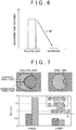
- FIG. 7 is a graph illustrating a surface roughness in a case where drilling is performed by use of a press, and a surface roughness in a case where drilling is performed by use of the laser drilling method according to the present embodiment.
- the upper-left view in FIG. 7 illustrates a horizontal direction (a right-and-left direction in a plane of paper) that is a pressing direction, and a vertical direction (an up-and-down direction in the plane of paper) that is perpendicular to the pressing direction, in the case where drilling is performed by use of a press.
- FIG. 7 illustrates a horizontal direction (the right-and-left direction in the plane of paper) that is an incidence direction of the laser beam LA, and a vertical direction (the up-and-down direction in the plane of paper) that is perpendicular to the incidence direction, in the case where drilling is performed by use of the laser drilling method according to the present embodiment.
- the laser drilling apparatus 100 has been described in terms of a case where the condenser lens 6 is placed on a vertically upper side with respect to the workpiece 7, and the laser beam LA condensed by the condenser lens 6 is vertically radiated to the surface of the workpiece 7.
- the present invention is not limited to this.
- the condenser lens 6 may be placed so as to be inclined at a given inclination angle to the vertically upper direction with respect to the workpiece 7, so as to radiate the laser beam LA to the surface of the workpiece 7 obliquely.
- the settings of the control parameters shown in the respective graphs of FIG. 5 are just examples, and the present invention is not limited to them.
- the ellipse angle may be kept at a predetermined value without any change from the time 0 to the time t2, and may be decreased to zero from the time t2 to the time t4.
- FIG. 9 it is possible to form the elliptical shape 13 of the upper-side hole of the through hole 8 so as to be rotated with respect to the elliptical shape 9 of the bottom-side hole of the through hole 8 in a top view. That is, it is possible to form the shape 9 of the bottom-side hole of the through hole 8 and the shape 13 of the upper-side hole thereof so that they have different phases.
- the radiation output of the laser beam LA for example, when a speed to decrease the output level after the time t2 is increased, it is possible for the depth of the surface of the through hole 8 to be scraped off by the laser beam LA to be further shallower from the through hole 8 toward the radial direction. This makes it possible to achieve a steeper inclination angle of the through hole 8. Further, when the speed to decrease the output level after the time t2 is further decreased, it is possible to further deepen the depth of the surface of the through hole 8 to be scraped off by the laser beam LA from the through hole 8 toward the radial direction. This makes it possible to achieve a more gradual inclination angle of the through hole 8. When the speed to decrease the radiation output is adjusted as such, it is possible to form the through hole 8 so as to have a steeper or more gradual inclination angle.
- the scanning radius of the laser beam LA for example, when a speed to increase the scanning radius after the time t2 is increased more, it is possible for the depth of the surface of the through hole 8 to be scraped off by the laser beam LA to be further shallower from the through hole 8 toward the radial direction. This makes it possible to achieve a steeper inclination angle of the through hole 8. Further, when the speed to increase the scanning radius after the time t2 is decreased more, it is possible to deepen the depth of the surface of the through hole 8 to be scraped off by the laser beam LA from the through hole 8 toward the radial direction. This makes it possible to achieve a more gradual inclination angle of the through hole 8. When the speed to increase the scanning radius is adjusted as such, it is possible to form the through hole 8 so as to have a steeper sharper or more gradual inclination angle.
- the present invention is not limited to the above embodiments, and various modifications can be made within a range which does not beyond the scope of the present invention as defined in the appended claims.
- the laser drilling method according to the present embodiment is applicable to a case where an injection port of a nozzle for injecting a fluid is machined, other than the case where an injection port of a fuel injection valve of an injector is machined.
Landscapes
- Physics & Mathematics (AREA)
- Optics & Photonics (AREA)
- Engineering & Computer Science (AREA)
- Plasma & Fusion (AREA)
- Mechanical Engineering (AREA)
- Laser Beam Processing (AREA)
Description
- The present invention relates to a laser drilling method and apparatus.
- With regard to a drilling method using a laser beam, Japanese Patent Application Publication No.
2004-243404 JP 2004-243404 A - However, in the laser drilling method of a related art, an inclination angle of the hole thus enlarged is 10 degrees at the maximum, and there is a possibility machining cannot be performed when a necessary inclination angle of a hole is larger than that. For example, in a case where an injection port of a fuel injection valve of an injector is machined, it is necessary for an inclination angle of a hole to be 40 degrees at the maximum. However, in the related art, it is difficult to machine such a large inclination angle. Note that, in the laser drilling method in the related art, in a case where the inclination angle of the hole is inclined at 10 degrees or more, it is necessary to use a larger condenser lens for a laser beam, or to shorten a distance from a lens to a workpiece, thereby resulting in that a laser drilling apparatus becomes very expensive.
- In the meantime, such a technique to perform drilling by use of a press without using a laser beam is considered, but drilling using a press cannot achieve expected accuracy for a surface roughness of a surface of a hole, so that there is a possibility that the surface of the hole cannot be finished smoothly. For example, in a case where drilling is performed by use of a press on an injection port of a fuel injection valve, there is a possibility that a requested minute surface roughness cannot be satisfied.
-
US6070813A , on which the preamble ofclaims US2011298156A1 discloses laser systems and methods for scribing or dicing semiconductor devices and/or severing electrically conductive links with laser pulses having shaped temporal profiles. - The present invention provides a laser drilling method and apparatus each of which is able to increase a degree of freedom of an inclination angle of a hole and is able to finish a surface of the hole smoothly.
- A laser drilling method according to one embodiment is a laser drilling method for performing drilling on a workpiece by use of a laser beam as defined in
claim 1, and the laser drilling method includes: scanning with the laser beam centered around a through hole toward a radial direction while changing a radiation output of the laser beam, after machining the through hole by radiating the laser beam to the workpiece. - Hereby, it is possible to increase a degree of freedom of an inclination angle of a hole and to finish a surface of the hole smoothly.
- Further, the radiation output of the laser beam may be changed to be smaller as the laser beam is distanced from the through hole in the radial direction. Hereby, it is possible to adjust a depth of an inclination angle of the through hole to a desired depth.
- Furthermore, the laser beam may be radiated in an idling manner at a position inside a diameter of the through hole, after machining the through hole. This makes it possible to improve machining efficiency.
- Further, a pulse energy of the laser beam, a repetition frequency of a pulse interval of a pulse of the laser beam, a scanning speed of the laser beam, and a radiation time in the scanning with the laser beam may be changed so as to change the radiation output of the laser beam.
- Furthermore, the laser beam may be radiated to the workpiece so that a shape of a bottom-side hole of the through hole and a shape of an upper-side hole of the through hole have different phases in a top view.
- Further, the laser beam may be radiated to the workpiece so that a shape of the through hole is a circular shape or an elliptical shape in a top view.
- Furthermore, the scanning with the laser beam may be performed in a spiral manner at the time of the scanning with the laser beam centered around the through hole toward the radial direction.
- A laser drilling apparatus according to another embodiment is a laser drilling apparatus for performing drilling on a workpiece by use of a laser as defined in
claim 8, and the laser drilling apparatus includes: a control section configured to scanning with the laser beam centered around the through hole toward a radial direction while changing a radiation output of the laser beam, after machining a through hole by radiating the laser beam to the workpiece. - Hereby, it is possible to increase a degree of freedom of an inclination angle of a hole and to finish a surface of the hole smoothly.
- According to the present invention, it is possible to provide a laser drilling method and apparatus each of which is able to increase a degree of freedom of an inclination angle of a hole and is able to finish a surface of the hole smoothly.
- Features, advantages, and technical and industrial significance of exemplary embodiments of the invention will be described below with reference to the accompanying drawings, in which like numerals denote like elements, and wherein:
-
FIG. 1 is a configuration diagram illustrating an example of a laser drilling apparatus according toEmbodiment 1; -
FIG. 2 is a flow chart illustrating an example of a flow of a machining process of a laser drilling method according toEmbodiment 1; -
FIG. 3A is a view to describe the machining process of the laser drilling method according toEmbodiment 1 in detail; -
FIG. 3B is a view to describe the machining process of the laser drilling method according toEmbodiment 1 in detail; -
FIG. 3C is a view to describe the machining process of the laser drilling method according toEmbodiment 1 in detail; -
FIG. 4 is a view to describe definitions of control parameters related to a locus of a laser beam LA according toEmbodiment 1; -
FIG. 5 is graphs illustrating settings of respective control parameters of the laser drilling apparatus according toEmbodiment 1; -
fig. 6 is a graph illustrating a machining time according toEmbodiment 1; -
FIG. 7 is a graph illustrating a surface roughness according toEmbodiment 1; -
FIG. 8 is a graph illustrating a setting of an ellipse angle according to another embodiment; and -
FIG. 9 is a view illustrating a shape of a through hole according to another embodiment. - The following describes concrete embodiments to which the present invention is applied in detail with reference to the drawings. Note that, in the following description, redundant descriptions are omitted as needed for clarification of the description.
- <
Embodiment 1>FIG. 1 is a configuration diagram illustrating an example of alaser drilling apparatus 100 according to the present embodiment. Thelaser drilling apparatus 100 includes alaser oscillator 1, agalvanometer mirror 2, amotor 3, a galvanometer mirror 4, a motor 5, acondenser lens 6, and a control section (not shown) that drive-controls each driving section such as thelaser oscillator 1 or the motor. - The
laser oscillator 1 is an ultrashort pulse laser that outputs a laser beam LA as pulsed light. In the present embodiment, thelaser oscillator 1 outputs a picosecond laser beam as the laser beam LA. - The
galvanometer mirror 2 polarizes, in a given direction, the laser beam LA emitted from thelaser oscillator 1. Themotor 3 rotates thegalvanometer mirror 2 in a given direction. Themotor 3 is controlled to rotate so that thegalvanometer mirror 2 is rotationally driven. Hereby, it is possible to polarize the laser beam LA emitted from thelaser oscillator 1, in a desired direction within a predetermined range. - The galvanometer mirror 4 polarizes, in a given direction, the laser beam LA polarized by the
galvanometer mirror 2. The motor 5 rotates the galvanometer mirror 4 in a given direction. The motor 5 is controlled to rotate so that the galvanometer mirror 4 is rotationally driven. Hereby, it is possible to polarize the laser beam LA polarized by thegalvanometer mirror 2, in a desired direction within a predetermined range. - The
condenser lens 6 condenses the laser beam LA polarized by the galvanometer mirror 4 on a surface of a workpiece 7. In the present embodiment, the laser beam LA is perpendicularly condensed on the surface of the workpiece 7. - The
laser drilling apparatus 100 polarizes the laser beam LA emitted from thelaser oscillator 1 by thegalvanometer mirror 2 and the galvanometer mirror 4, condenses the polarized laser beam LA by thecondenser lens 6, and radiates the condensed laser beam LA to the workpiece 7. Accordingly, thelaser drilling apparatus 100 radiates the laser beam LA emitted from thelaser oscillator 1, such that the laser beam LA is aligned by thegalvanometer mirrors 2, 4 at a given position in a machining region of the surface of the workpiece 7. Then, thelaser drilling apparatus 100 swings thegalvanometer mirrors 2, 4 in respective directions shown by arrows in the figure in a reciprocating manner, so as to performing scanning with the laser beam LA on the machining region of the surface of the workpiece 7, thereby performing drilling on the workpiece 7. - The
laser drilling apparatus 100 performs scanning on the workpiece 7 with the laser beam LA so that a locus of the laser beam LA draws a desired shape. The lower-left view inFIG. 1 is a schematic view illustrating the locus of the laser beam LA at the time when thelaser drilling apparatus 100 performs scanning with the laser beam LA. An example illustrated in this figure illustrates a circular scan diameter of a case where the locus of the laser beam LA has a circular shape, and an elliptical scan diameter of a case where the locus of the laser beam LA has an elliptical shape. Note that the locus of the laser beam LA is not limited to them, and the scanning may be performed so that the laser beam draws other given shapes. - Referring now to
FIG. 2 , a flow of the machining process of the laser drilling method according to the present embodiment is described. According to the present invention, initially thelaser drilling apparatus 100 radiates the laser beam LA to the workpiece 7 so as to machine a through hole (step S100). Subsequently, thelaser drilling apparatus 100 performs scanning with the laser beam LA from the through hole toward a radial direction while changing a radiation output of the laser beam LA (step S200). - Thus, after the through hole is formed, the scanning is performed, according to the present invention, with the laser beam LA in the radial direction while the radiation output of the laser beam LA is changed, thereby making it possible to enlarge an inclination angle of the hole to a given angle. This makes it possible to increase a degree of freedom of the inclination angle of the hole. Further, since the scanning is performed with the laser beam LA in the radial direction while the radiation output of the laser beam LA is changed, it is possible to improve a surface roughness of a surface of the hole to desired accuracy. This makes it possible to finish the surface of the hole smoothly.
- Referring now to
FIGS. 3A to 3C , the following describes the machining process of the laser drilling method according to the present invention in detail. As illustrated inFIG. 3A , the laser drilling method according to the present invention includesstep 1 illustrated in the left view in the figure, andstep 2 illustrated in the right view in the figure.Step 1 is a step of radiating the laser beam LA to the workpiece 7 so as to machine a throughhole 8, and corresponds to S100 illustrated inFIG. 2 .Step 2 is a step of performing scanning with the laser beam LA from the formed throughhole 8 toward the radial direction while changing the radiation output of the laser beam LA, and corresponds to S200 illustrated inFIG. 2 . Note that the radial direction indicates a direction away from the throughhole 8 formed instep 1. -
FIGS. 3B and3C are schematic views to describe contents of the machining process instep 1 andstep 2 illustrated inFIG. 3A in detail.FIG. 3B is a top view schematically illustrating a shape of a bottom-side hole of the throughhole 8 or the locus of the laser beam LA.FIG. 3C is a sectional view schematically illustrating the workpiece 7 with regard to a line X-X' inFIG. 3A . - Initially,
step 1 illustrated in the left view inFIG. 3A is described with reference to the leftmost schematic view inFIG. 3B and the leftmost schematic view inFIG. 3C . As illustrated in the left view inFIG 3A , thelaser drilling apparatus 100 radiates the laser beam LA to the workpiece 7 so as to form the throughhole 8 that penetrates through the workpiece 7. As illustrated in the view in the left view inFIG. 3A and the leftmost view inFIG. 3C , thelaser drilling apparatus 100 forms the throughhole 8 by performing rotational scanning with the laser beam LA in a rotating arrow direction (a circumferential direction) shown herein. In the present embodiment, as illustrated in the leftmost schematic view inFIG. 3B , ashape 9 of the bottom-side hole of the throughhole 8 thus formed is an elliptical shape. Note that, in the leftmost schematic view inFIG. 3B , a spot of the laser beam LA in the scanning is indicated by A. - Note that the
shape 9 of the bottom-side hole of the throughhole 8 is not limited to the elliptical shape, and can be formed in a given circular shape or a given elliptical shape having a desired diameter. Further, a scanning method with the laser beam LA at the time of forming the throughhole 8 is not limited to the rotational scanning, and any other well-known scanning method may be employed provided that the scanning method is able to form theshape 9 of the bottom-side hole of the throughhole 8 in a given circular shape or a given elliptical shape having a desired diameter. - Then, in
step 2 illustrated in the right view inFIG. 3A , after the throughhole 8 is formed, thelaser drilling apparatus 100 performs scanning with the laser beam LA from the throughhole 8 thus formed toward the radial direction while changing the radiation output of the laser beam LA, as illustrated in the figure. A state of the scanning with the laser beam LA and the machining of the throughhole 8 at this time is described with reference to the second to fourth schematic views from the left inFIG. 3B and the second to fourth schematic views from the left inFIG. 3C . - Initially, as illustrated in the second schematic view from the left in
FIG. 3B and the second schematic view from the left inFIG. 3C , after forming the throughhole 8, thelaser drilling apparatus 100 performs scanning with the laser beam LA on an inner region of theshape 9 of the bottom-side hole of the throughhole 8. The second schematic view from the left inFIG. 3B illustrates alocus 10 of the laser beam LA at this time. Further, in synchronization with such scanning with the laser beam LA, thelaser drilling apparatus 100 decreases a level of the radiation output of the laser beam LA from an output level at the time of forming the throughhole 8, to a predetermined output level. Note that, in the second schematic view from the left inFIG. 3B , a spot of the laser beam LA in the scanning is indicated by B. - Note that the scanning with the laser beam LA at this time is not limited to the rotational scanning, and the laser beam LA may be radiated to a predetermined fixed position inside a diameter of the bottom-side hole of the through
hole 8. - As such, at a timing when the level of the radiation output of the laser beam LA is decreased to the predetermined level from the level at the time of forming the through
hole 8, thelaser drilling apparatus 100 radiates the laser beam LA not directly to the workpiece 7, but in an idling manner in a region inside theshape 9 of the bottom-side hole of the throughhole 8. - Hereby, in a case where the laser beam LA is radiated so as to form the through
hole 8 in the workpiece 7 and then the scanning with the laser beam LA is performed toward the radial direction centered around the throughhole 8 thus formed, it is possible to surely prevent the laser beam LA from being radiated to theshape 9 of the bottom-side hole of the throughhole 8 thus formed. Further, when the throughhole 8 is formed, the laser beam LA of a high output level is used, thereby making it possible to from the throughhole 8 in a short time. - Subsequently, as illustrated in the third schematic view from the left in
FIG. 3B and the third schematic view from the left inFIG. 3C , after decreasing the radiation output of the laser beam LA to the predetermined level, thelaser drilling apparatus 100 performs scanning with the laser beam LA toward the radial direction from the throughhole 8 thus formed. As illustrated in the right view inFIG. 3A and the third to fourth views from the left inFIG. 3C , for example, thelaser drilling apparatus 100 performs rotational scanning with the laser beam LA in rotating arrow directions in the views and performs scanning the laser beam LA so as to enlarge a locus of the laser beam LA in the radial direction. The third schematic view from the left inFIG. 3B illustrates a locus 11 of the laser beam LA in the middle of this scanning, and the locus 11 draws a perfect circle shape. Further, the fourth schematic view from the left inFIG. 3B illustrates alocus 12 of the laser beam LA at a timing when the scanning with the laser beam LA is finished, and thelocus 12 draws an oblong elliptical shape. Further, the elliptical shape that thelocus 12 draws corresponds to ashape 13 of an upper-side hole of the throughhole 8. Note that, in the third and fourth schematic views from the left inFIG. 3B , spots of the laser beam LA at the time of scanning are indicated by C, D. - In the present embodiment, at the time of performing scanning with the laser beam LA, the
laser drilling apparatus 100 performs the scanning from the throughhole 8 toward the radial direction while rotating the laser beam LA in a circumferential direction. At this time, thelaser drilling apparatus 100 radiates the laser beam LA from a center of the throughhole 8 toward the radial direction in a spiral manner, for example. Note that the scanning with the laser beam is not limited to the spiral manner, and the laser beam LA may be radiated concentrically from the throughhole 8 toward the radial direction. - Further, in synchronization with such scanning with the laser beam LA, the
laser drilling apparatus 100 decreases the level of the radiation output of the laser beam LA as a scanning diameter of the laser beam LA is distanced from the throughhole 8 in the radial direction. Hereby, the radiation output of the laser beam LA to be radiated to the workpiece 7 is changed to be smaller as the laser beam LA is distanced from the throughhole 8 in the radial direction. - As illustrated in the right view in
FIG. 3A and the third to fourth views from the left inFIG. 3C , according to such scanning, a depth of the surface of the throughhole 8 to be scraped off by the laser beam LA becomes shallower as it goes away from the throughhole 8 in the radial direction. As a result, it is possible to enlarge the inclination angle of the throughhole 8 toward the radial direction after the throughhole 8 is formed. - Further, after the through
hole 8 is formed, the scanning with the laser beam LA is performed toward the radial direction from the throughhole 8 thus formed, thereby making it possible to efficiently remove, from the throughhole 8 thus formed, plasma and sublimated deposits on a machining surface of the throughhole 8 in non-penetration machining illustrated in the third and fourth views from the left inFIG. 3C . Further, by scraping off the surface of the throughhole 8 from the throughhole 8 toward the radial direction (that is, from an inside to an outside), it is possible to efficiently remove sublimated deposits and the like toward the throughhole 8 without depositing the sublimated deposits on the surface. This consequently makes it possible to improve machining efficiency. - Referring now to
FIGS. 4 and5 , the following describes those various control parameters (the radiation output of the laser beam LA, an ellipse angle, a scanning radius, an ellipticity) of thelaser drilling apparatus 100 which are set at the time of drilling control. -
FIG. 4 is a view to describe definitions of control parameters related to the locus of the laser beam LA. InFIG. 4 , in a case where the locus of the laser beam LA has an elliptical shape (or a circular shape), X, Y respectively indicate a long diameter and a short diameter of the elliptical shape. The scanning radius indicates a magnitude of the long diameter X of the ellipse. The ellipticity indicates a rate of the long diameter to the short diameter (that is, X/Y). The number of rotations indicates the number of times of rotation scanning with the laser beam LA for one minute in the circumferential direction. The ellipse angle indicates a turning angle of the elliptical shape of the throughhole 8 with respect to an X-axis (a right direction on a plane of paper) in a top view. InFIG. 4 , a turning angle of the elliptical shape of the bottom-side hole of the throughhole 8 with respect to the X-axis is zero. That is, an ellipse angle of anelliptical shape 9 of the bottom-side hole of the throughhole 8 is zero. In view of this, an ellipse angle of anelliptical shape 13 of the upper-side hole of the throughhole 8 also indicates a turning angle of theelliptical shape 13 of the upper-side hole of the throughhole 8 with respect to theelliptical shape 9 of the bottom-side hole of the throughhole 8. -
FIG. 5 is graphs illustrating settings of respective control parameters of thelaser drilling apparatus 100 at the time of drilling. In each graph ofFIG. 5 ,times 0 to t1 correspond to step 1 of radiating the laser beam LA to the workpiece 7 so as to machine the throughhole 8. Further, a step from the time t1 to a time t4 corresponds to the step of performing scanning with the laser beam LA from the formed throughhole 8 toward the radial direction while decreasing the radiation output of the laser beam LA. - As illustrated in the upper-left graph of
FIG. 5 , thelaser drilling apparatus 100 radiates the laser beam at a given high output level from thetime 0 to the time t1. Here, the given high output level is an output level that allows the laser beam to penetrate through the workpiece 7. Further, as illustrated in the upper-right graph ofFIG. 5 , thelaser drilling apparatus 100 performs scanning with the laser beam LA toward the radial direction of the throughhole 8 from thetime 0 to the time t1 by increasing the scanning radius of the laser beam. Further, as illustrated in the lower-right graph ofFIG. 5 , thelaser drilling apparatus 100 keeps the ellipticity at a predetermined value without any change from thetime 0 to the time t1. Note that, as illustrated in the lower-left graph ofFIG. 5 , thelaser drilling apparatus 100 keeps the ellipse angle at zero without any change from thetime 0 to the time t1. - Hereby, the
laser drilling apparatus 100 forms theshape 9 of the bottom-side hole of the throughhole 8 as illustrated in the left view inFIG. 3A and the leftmost view inFIG. 3C . Theshape 9 is an elliptical shape that satisfies the ellipse angle and the ellipticity respectively shown in the lower-left graph and the lower-right graph inFIG. 5 . -
Step 2 from the time t1 to the time t4 includes a step from the time t1 to the time t2 and a step from the time t2 to the time t4 (a step from the time t2 to the time t3 and a step from the time t3 to the time t4). - First described is the step from the time t1 to the time t2. As illustrated in the upper-left graph of
FIG. 5 , thelaser drilling apparatus 100 decreases the level of the radiation output of the laser beam LA from the high output level at the time of forming the throughhole 8 to a given output level from thetime 1 to the time t2. Here, the given output level is an output level that does not allow the laser beam to penetrate through the workpiece 7. Further, as illustrated in the upper-right graph ofFIG. 5 , thelaser drilling apparatus 100 decreases the scanning radius of the laser beam LA from the time t1 to the time t2 so that the scanning radius is smaller than that at the time t1. Note that, as respectively shown in the lower-left graph and the lower-right graph ofFIG. 5 , thelaser drilling apparatus 100 keeps the ellipse angle and the ellipticity at original values without any change from the time t1 to the time t2. - Hereby, as illustrated in the second schematic view from the left in
FIG. 3B and the second schematic view from the left inFIG. 3C , after forming the throughhole 8, thelaser drilling apparatus 100 performs scanning with the laser beam LA in the region inside theshape 9 of the bottom-side hole of the throughhole 8. - Next will be described the step from the time t2 to the time t4. The step from the t2 to the time t4 corresponds to the step of performing scanning with the laser beam LA from the formed through
hole 8 toward the radial direction while decreasing the radiation output of the laser beam LA. - As illustrated in the upper-left graph of
FIG. 5 , thelaser drilling apparatus 100 starts with the given output level at the time t2 as the level of the radiation output of the laser beam LA, and further decreases the level of the radiation output from thetime 2 to the time 4. Further, as illustrated in the upper-right graph ofFIG. 5 , thelaser drilling apparatus 100 performs scanning with the laser beam LA toward the radial direction of the throughhole 8 from the time t2 to the time t4 by increasing the scanning radius of the laser beam. Further, as illustrated in the lower-right graph ofFIG. 5 , thelaser drilling apparatus 100 increases the ellipticity from the time t2 to the time t4. Note that, as illustrated in the lower-left graph ofFIG. 5 , thelaser drilling apparatus 100 keeps the ellipse angle at zero without any change from the time t2 to the time t4. - By performing such scanning, the
laser drilling apparatus 100 draws the locus 11 of the laser beam LA as illustrated in the third view from the left inFIG. 3B , at the time t3. Further, thelaser drilling apparatus 100 draws thelocus 12 of the laser beam LA as illustrated in the fourth view from the left inFIG. 3B , at the time t4. - Hereby, from the time t2 to the time t4, the
laser drilling apparatus 100 is able to enlarge the inclination angle of the throughhole 8 toward the radial direction as illustrated in the right view inFIG. 3A and the third to fourth views from the left inFIG. 3C . Further, by changing the ellipticity as such, it is possible to form, as theshape 13 of the upper-side hole of the throughhole 8, an elliptical shape having an ellipticity different from that of theelliptical shape 9 of the bottom-side hole of the formed throughhole 8. - Note that the
laser oscillator 1 is able to change the radiation output of the laser beam LA by controlling radiation control parameters. The radiation parameters include a pulse energy of the laser beam LA, a repetition frequency of a pulse interval of a pulse of the laser beam LA, a scanning speed of the laser beam LA, and a radiation time in the scanning with the laser beam LA. In view of this, it is possible to change the radiation output of the laser beam LA to be small by performing at least one of the following setting: setting the pulse energy of the laser beam LA to be small; setting the repetition frequency of the pulse interval of the pulse of the laser beam LA to be lower; setting the scanning speed in the rotational scanning with the laser beam LA to be slow; and setting the scanning time in the rotational scanning with the laser beam LA to be short. Further, in addition to the radiation control parameters, a spot diameter of the laser beam LA may be changed. - Referring to
FIGS. 6 and 7 , the following describes effects of the present embodiment.FIG. 6 is a graph illustrating a machining time for a laser drilling method according to the related art, and a machining :ime for the laser drilling method according to the present invention. Note that the following description deals with the technique described in Japanese Patent Application Publication No.10-245711 A JP 10-245711 A hole 8 to be formed is configured such that a phase of theelliptical shape 9 on a bottom side of the throughhole 8 is displaced by 90 degrees from a phase of theelliptical shape 13 on an upper side of the throughhole 8. - In the related art, it is necessary to radiate a laser beam LA to a surface of a workpiece 7 to scrape off layers of the surface one by one, in order to form a through
hole 8. However, in the related art, there is no method for efficiently removing deposits caused when the layers are scraped off one by one, and therefore, it is necessary to remove the deposits each time when one layer is scraped off. Because of this, only a few amount of the deposits can be scrape off at once, so that it takes much time to completely form the throughhole 8. Further, in a case where the layers are scraped off one by one as such, it is difficult to secure a necessary surface roughness of the surface. - On the other hand, according to the present embodiment, it is possible to form the through
hole 8 having the same shape in the workpiece 7 in a shorter time as mentioned earlier. Consequently, as illustrated inFIG. 6 , it is possible to perform machining in a time that is about one hundredth shorter than a time required in the related art. -
FIG. 7 is a graph illustrating a surface roughness in a case where drilling is performed by use of a press, and a surface roughness in a case where drilling is performed by use of the laser drilling method according to the present embodiment. Note that the upper-left view inFIG. 7 illustrates a horizontal direction (a right-and-left direction in a plane of paper) that is a pressing direction, and a vertical direction (an up-and-down direction in the plane of paper) that is perpendicular to the pressing direction, in the case where drilling is performed by use of a press. The upper-right view inFIG. 7 illustrates a horizontal direction (the right-and-left direction in the plane of paper) that is an incidence direction of the laser beam LA, and a vertical direction (the up-and-down direction in the plane of paper) that is perpendicular to the incidence direction, in the case where drilling is performed by use of the laser drilling method according to the present embodiment. - As shown on the left side of the graph in
FIG. 7 , in the case where drilling is performed by use of a press, a good surface roughness can be achieved in the horizontal direction in the drilling, but a surface roughness is largely decreased in the vertical direction that is perpendicular to the pressing direction. - On the other hand, as shown on the right side of the graph in
FIG. 7 , in the case where drilling is performed by use of the laser drilling method according to the present embodiment, a good surface roughness is achieved in the horizontal direction in the drilling. Further, a good surface roughness is achieved in the vertical direction. In view of this, according to the laser drilling method of the present embodiment, it is possible to achieve a good surface roughness in either of the horizontal direction and the vertical direction. Hereby, even in a case of drilling for an injection port of a fuel injection valve or the like, for example, it is possible to satisfy a requested surface roughness. - <Another Embodiment> The
laser drilling apparatus 100 according to the above embodiment has been described in terms of a case where thecondenser lens 6 is placed on a vertically upper side with respect to the workpiece 7, and the laser beam LA condensed by thecondenser lens 6 is vertically radiated to the surface of the workpiece 7. However, the present invention is not limited to this. For example, thecondenser lens 6 may be placed so as to be inclined at a given inclination angle to the vertically upper direction with respect to the workpiece 7, so as to radiate the laser beam LA to the surface of the workpiece 7 obliquely. - Further, the settings of the control parameters shown in the respective graphs of
FIG. 5 are just examples, and the present invention is not limited to them. For example, with regard to the ellipse angle, as illustrated in the graph ofFIG. 8 , the ellipse angle may be kept at a predetermined value without any change from thetime 0 to the time t2, and may be decreased to zero from the time t2 to the time t4. In this case, as illustrated inFIG. 9 , it is possible to form theelliptical shape 13 of the upper-side hole of the throughhole 8 so as to be rotated with respect to theelliptical shape 9 of the bottom-side hole of the throughhole 8 in a top view. That is, it is possible to form theshape 9 of the bottom-side hole of the throughhole 8 and theshape 13 of the upper-side hole thereof so that they have different phases. - Further, with regard to the radiation output of the laser beam LA, for example, when a speed to decrease the output level after the time t2 is increased, it is possible for the depth of the surface of the through
hole 8 to be scraped off by the laser beam LA to be further shallower from the throughhole 8 toward the radial direction. This makes it possible to achieve a steeper inclination angle of the throughhole 8. Further, when the speed to decrease the output level after the time t2 is further decreased, it is possible to further deepen the depth of the surface of the throughhole 8 to be scraped off by the laser beam LA from the throughhole 8 toward the radial direction. This makes it possible to achieve a more gradual inclination angle of the throughhole 8. When the speed to decrease the radiation output is adjusted as such, it is possible to form the throughhole 8 so as to have a steeper or more gradual inclination angle. - Further, with regard to the scanning radius of the laser beam LA, for example, when a speed to increase the scanning radius after the time t2 is increased more, it is possible for the depth of the surface of the through
hole 8 to be scraped off by the laser beam LA to be further shallower from the throughhole 8 toward the radial direction. This makes it possible to achieve a steeper inclination angle of the throughhole 8. Further, when the speed to increase the scanning radius after the time t2 is decreased more, it is possible to deepen the depth of the surface of the throughhole 8 to be scraped off by the laser beam LA from the throughhole 8 toward the radial direction. This makes it possible to achieve a more gradual inclination angle of the throughhole 8. When the speed to increase the scanning radius is adjusted as such, it is possible to form the throughhole 8 so as to have a steeper sharper or more gradual inclination angle. - Further, needless to say, the present invention is not limited to the above embodiments, and various modifications can be made within a range which does not beyond the scope of the present invention as defined in the appended claims. For example, the laser drilling method according to the present embodiment is applicable to a case where an injection port of a nozzle for injecting a fluid is machined, other than the case where an injection port of a fuel injection valve of an injector is machined.
Claims (14)
- A laser drilling method for performing drilling on a workpiece (7) by use of a laser beam, the laser drilling method comprising:machining a through hole (8) by radiating the laser beam to the workpiece (7); and characterised by the following step :scanning with the laser beam centered around the through hole (8) toward a radial direction while changing a radiation output of the laser beam to enlarge an inclination angle of the through hole.
- The laser drilling method according to claim 1, further comprising:changing the radiation output of the laser beam to be smaller as the laser beam is distanced from the through hole (8) in the radial direction.
- The laser drilling method according to claim 1 or 2, further comprising:radiating the laser beam in an idling manner at a position inside a diameter of the through hole (8), after machining the through hole (8).
- The laser drilling method according to any one of claims 1 to 3, further comprising:changing a pulse energy of the laser beam, a repetition frequency of a pulse interval of a pulse of the laser beam, a scanning speed of the laser beam, and a radiation time in the scanning with the laser beam, so as to change the radiation output of the laser beam.
- The laser drilling method according to any one of claims 1 to 4, further comprising:radiating the laser beam to the workpiece (7) so that a shape of a bottom-side hole of the through hole (8) and a shape of an upper-side hole of the through hole (8) have different phases in a top view.
- The laser drilling method according to any one of claims 1 to 5, further comprising:radiating the laser beam to the workpiece (7) so that a shape of the through hole (8) is a circular shape or an elliptical shape in a top view.
- The laser drilling method according to any one of claims 1 to 6, further comprising:scanning with the laser beam in a spiral manner at the time of the scanning with the laser beam centered around the through hole (8) toward the radial direction.
- A laser drilling apparatus (100) that performs drilling on a workpiece (7) by use of a laser beam, the laser drilling apparatus (100) characterized by comprising:a control section configured to perform machining of a through hole (8) by radiating the laser beam to the workpiece (7), and scanning with the laser beam centered around the through hole (8) toward a radial direction while changing a radiation output of the laser beam to enlarge an inclination angle of the through hole, after machining the through hole (8) by radiating the laser beam to the workpiece (7).
- The laser drilling apparatus (100) according to claim 8, wherein:the control section is configured to change the radiation output of the laser beam to be smaller as the laser beam is distanced from the through hole (8) in the radial direction.
- The laser drilling apparatus (100) according to claim 8 or 9, wherein:the control section is configured to radiate the laser beam in an idling manner at a position inside a diameter of the through hole (8), after machining the through hole (8).
- The laser drilling apparatus (100) according to any one of claims 8 to 10, wherein:the control section is configured to change a pulse energy of the laser beam, a repetition frequency of a pulse interval of a pulse of the laser beam, a scanning speed of the laser beam, and a radiation time in the scanning with the laser beam, so as to change the radiation output of the laser beam.
- The laser drilling apparatus (100) according to any one of claims 8 to 11, wherein:the control section is configured to radiate the laser beam to the workpiece (7) so that a shape of a bottom-side hole of the through hole (8) and a shape of an upper-side hole of the through hole (8) have different phases in a top view.
- The laser drilling apparatus (100) according to any one of claims 8 to 12, wherein:the control section is configured to radiate the laser beam to the workpiece (7) so that a shape of the through hole (8) is a circular shape or an elliptical shape.
- The laser drilling apparatus (100) according to any one of claims 8 to 13, wherein:the control section is configured to perform the scanning with the laser beam in a spiral manner at the time of the scanning with the laser beam centered around the through hole (8) toward the radial direction.
Priority Applications (1)
| Application Number | Priority Date | Filing Date | Title |
|---|---|---|---|
| PL14727050T PL2994263T3 (en) | 2013-05-09 | 2014-05-06 | Laser drilling method and apparatus with radiation output changes in a radial direction during drilling of a workpiece |
Applications Claiming Priority (2)
| Application Number | Priority Date | Filing Date | Title |
|---|---|---|---|
| JP2013099147A JP5994723B2 (en) | 2013-05-09 | 2013-05-09 | Laser drilling method and apparatus |
| PCT/IB2014/000742 WO2014181173A1 (en) | 2013-05-09 | 2014-05-06 | Laser drilling method and apparatus with radiation output changes in a radial direction during drilling of a workpiece |
Publications (2)
| Publication Number | Publication Date |
|---|---|
| EP2994263A1 EP2994263A1 (en) | 2016-03-16 |
| EP2994263B1 true EP2994263B1 (en) | 2017-06-21 |
Family
ID=50841898
Family Applications (1)
| Application Number | Title | Priority Date | Filing Date |
|---|---|---|---|
| EP14727050.8A Active EP2994263B1 (en) | 2013-05-09 | 2014-05-06 | Laser drilling method and apparatus with radiation output changes in a radial direction during drilling of a workpiece |
Country Status (7)
| Country | Link |
|---|---|
| US (1) | US10300559B2 (en) |
| EP (1) | EP2994263B1 (en) |
| JP (1) | JP5994723B2 (en) |
| CN (1) | CN105189018B (en) |
| HU (1) | HUE036304T2 (en) |
| PL (1) | PL2994263T3 (en) |
| WO (1) | WO2014181173A1 (en) |
Families Citing this family (12)
| Publication number | Priority date | Publication date | Assignee | Title |
|---|---|---|---|---|
| JP6335590B2 (en) * | 2014-03-31 | 2018-05-30 | パナソニック デバイスSunx株式会社 | Laser processing apparatus and lens unit |
| DE102016106067A1 (en) * | 2016-04-04 | 2017-10-05 | Trumpf Werkzeugmaschinen Gmbh + Co. Kg | Method and processing machine for the cutting processing of plate-shaped or rod-shaped workpieces |
| JP2018006509A (en) * | 2016-06-30 | 2018-01-11 | 三星ダイヤモンド工業株式会社 | Processing method of substrate and processing device |
| DE112017007622A5 (en) * | 2017-06-09 | 2020-07-02 | Bystronic Laser Ag | METHOD FOR CONTROLLING A BEAM CUTTING DEVICE WITH A CUTTING TOOL, A COMPUTER-IMPLEMENTED METHOD FOR AUTOMATICALLY DETERMINING AND GENERATING MOVEMENT COMMANDS FOR CONTROLLING A CUTTING TOOL OF A BEAM-CUTTING CUTTER |
| US11660899B2 (en) * | 2017-11-07 | 2023-05-30 | Sumitomo Electric Sintered Alloy. Ltd. | Iron-based sintered body, method for laser-marking the same, and method for manufacturing the same |
| US11524366B2 (en) * | 2018-07-26 | 2022-12-13 | Coherent Munich GmbH & Co. KG | Separation and release of laser-processed brittle material |
| WO2020069231A1 (en) * | 2018-09-28 | 2020-04-02 | Synfuel Americas Corporation | Laser cutting system for cutting articles and forming filtration tubes |
| CN110976439B (en) * | 2019-12-24 | 2020-10-20 | 中国科学院半导体研究所 | Laser cleaning mode and equipment for improving uniformity of laser cleaning surface |
| KR102324548B1 (en) * | 2019-12-31 | 2021-11-10 | (주)미래컴퍼니 | Laser machining system and laser machining method |
| DE102020201207A1 (en) * | 2020-01-31 | 2021-08-05 | Fraunhofer-Gesellschaft zur Förderung der angewandten Forschung e.V. | Arrangement for material processing with a laser beam, in particular for laser beam drilling |
| KR102363046B1 (en) * | 2021-08-18 | 2022-02-15 | 주식회사 21세기 | A method for processing micro-hole of upper mold used for laminating a thin film sheet using femtosecond pulsed laser |
| CN114346456A (en) * | 2022-01-26 | 2022-04-15 | 扬昕科技(苏州)有限公司 | Processing method of light guide plate mold core and processing equipment of light guide plate mold core |
Citations (5)
| Publication number | Priority date | Publication date | Assignee | Title |
|---|---|---|---|---|
| US6070813A (en) | 1998-08-11 | 2000-06-06 | Caterpillar Inc. | Laser drilled nozzle in a tip of a fuel injector |
| WO2004011186A1 (en) | 2002-07-25 | 2004-02-05 | Matsushita Electric Industrial Co., Ltd. | Inkjet nozzle and process of laser drilling a hole for use in inkjet nozzles |
| JP2004243404A (en) | 2003-02-17 | 2004-09-02 | Internatl Business Mach Corp <Ibm> | Hole forming method and hole forming apparatus |
| EP1353773B1 (en) | 2001-11-30 | 2010-04-14 | Panasonic Corporation | Method of and system for laser milling |
| US20110298156A1 (en) | 2008-03-31 | 2011-12-08 | Electro Scientific Industries, Inc. | Methods and systems for laser processing a workpiece using a plurality of tailored laser pulse shapes |
Family Cites Families (15)
| Publication number | Priority date | Publication date | Assignee | Title |
|---|---|---|---|---|
| JPH0542337A (en) | 1991-08-08 | 1993-02-23 | Amada Co Ltd | Method for forming free curved surface by laser beam |
| JPH10245711A (en) | 1997-02-27 | 1998-09-14 | Idemitsu Petrochem Co Ltd | Helmet with transparent visor |
| JP3800795B2 (en) * | 1998-02-23 | 2006-07-26 | 富士ゼロックス株式会社 | Laser processing condition automatic setting method and laser processing condition automatic setting device |
| JP2000071086A (en) | 1998-08-31 | 2000-03-07 | Yasuoka:Kk | Method and device for shape processing by laser light |
| US6501045B1 (en) * | 2000-04-06 | 2002-12-31 | Resonetics, Inc. | Method and apparatus for controlling the taper angle of the walls of laser machined features |
| JP4320926B2 (en) | 2000-06-16 | 2009-08-26 | パナソニック株式会社 | Laser drilling method and apparatus |
| US7411150B2 (en) * | 2002-06-12 | 2008-08-12 | Alstom Technology Ltd. | Method of producing a composite component |
| CN1323797C (en) * | 2002-07-25 | 2007-07-04 | 松下电器产业株式会社 | Inkjet nozzle and process of laser drilling a hole for use in inkjet nozzles |
| JP2004058118A (en) * | 2002-07-31 | 2004-02-26 | Kyocera Corp | Method for drilling ceramic substrate |
| JP4635839B2 (en) * | 2005-11-15 | 2011-02-23 | トヨタ自動車株式会社 | Drilling method and drilling device |
| US20070148567A1 (en) * | 2005-12-09 | 2007-06-28 | Joerg Ferber | Method and apparatus for laser-drilling an inkjet orifice in a substrate |
| JP2008254327A (en) * | 2007-04-05 | 2008-10-23 | Sharp Corp | Laser processing method, nozzle plate manufacturing method using the same, and inkjet head |
| JP2012066265A (en) * | 2010-09-22 | 2012-04-05 | Panasonic Corp | Laser processing method |
| JP5308431B2 (en) * | 2010-12-06 | 2013-10-09 | 三星ダイヤモンド工業株式会社 | Line processing method and laser processing apparatus using laser light |
| JP5772495B2 (en) | 2011-10-21 | 2015-09-02 | トヨタ自動車株式会社 | Fuel injection valve |
-
2013
- 2013-05-09 JP JP2013099147A patent/JP5994723B2/en active Active
-
2014
- 2014-05-06 HU HUE14727050A patent/HUE036304T2/en unknown
- 2014-05-06 EP EP14727050.8A patent/EP2994263B1/en active Active
- 2014-05-06 US US14/890,030 patent/US10300559B2/en active Active
- 2014-05-06 WO PCT/IB2014/000742 patent/WO2014181173A1/en not_active Ceased
- 2014-05-06 PL PL14727050T patent/PL2994263T3/en unknown
- 2014-05-06 CN CN201480025568.7A patent/CN105189018B/en active Active
Patent Citations (5)
| Publication number | Priority date | Publication date | Assignee | Title |
|---|---|---|---|---|
| US6070813A (en) | 1998-08-11 | 2000-06-06 | Caterpillar Inc. | Laser drilled nozzle in a tip of a fuel injector |
| EP1353773B1 (en) | 2001-11-30 | 2010-04-14 | Panasonic Corporation | Method of and system for laser milling |
| WO2004011186A1 (en) | 2002-07-25 | 2004-02-05 | Matsushita Electric Industrial Co., Ltd. | Inkjet nozzle and process of laser drilling a hole for use in inkjet nozzles |
| JP2004243404A (en) | 2003-02-17 | 2004-09-02 | Internatl Business Mach Corp <Ibm> | Hole forming method and hole forming apparatus |
| US20110298156A1 (en) | 2008-03-31 | 2011-12-08 | Electro Scientific Industries, Inc. | Methods and systems for laser processing a workpiece using a plurality of tailored laser pulse shapes |
Also Published As
| Publication number | Publication date |
|---|---|
| PL2994263T3 (en) | 2017-12-29 |
| EP2994263A1 (en) | 2016-03-16 |
| US20160082549A1 (en) | 2016-03-24 |
| US10300559B2 (en) | 2019-05-28 |
| CN105189018A (en) | 2015-12-23 |
| JP2014217860A (en) | 2014-11-20 |
| JP5994723B2 (en) | 2016-09-21 |
| HUE036304T2 (en) | 2018-06-28 |
| WO2014181173A1 (en) | 2014-11-13 |
| CN105189018B (en) | 2017-03-22 |
Similar Documents
| Publication | Publication Date | Title |
|---|---|---|
| US10300559B2 (en) | Laser drilling method and apparatus with radiation output changes in a radial direction during drilling of a workpiece | |
| CN102091875B (en) | For forming laser process equipment and the method on surface in unfinished products | |
| JP5917862B2 (en) | Processing object cutting method | |
| KR100462358B1 (en) | Laser Processing Apparatus with Polygon Mirror | |
| JP6516184B2 (en) | Apparatus and method for slicing brittle substrate | |
| JP2017071074A (en) | Method for manufacturing internal processed layer forming single crystal substrate, and method for manufacturing single crystal substrate | |
| JP6362130B2 (en) | Laser processing method and laser processing apparatus | |
| CN105121088B (en) | Laser processing apparatus and method of processing workpieces via laser tool manipulation | |
| KR102363046B1 (en) | A method for processing micro-hole of upper mold used for laminating a thin film sheet using femtosecond pulsed laser | |
| JP2011526211A5 (en) | ||
| WO2011016176A1 (en) | Pulse laser machining apparatus and pulse laser machining method | |
| JP6910086B1 (en) | Laser processing equipment, laser processing system, rotator unit equipment, laser processing method, and probe card production method | |
| CN105598593A (en) | Laser processing system and method used for hard and brittle material drilling | |
| CN106232282B (en) | Method for producing small holes in workpieces by varying operating parameters within beam pulses | |
| JP2013173150A (en) | Laser beam machining device and laser beam machining method | |
| US7728257B2 (en) | Method of forming embrittled areas inside wafer for division | |
| JP5873978B2 (en) | Laser processing method and nozzle manufacturing method | |
| CN115697625A (en) | Method for creating recesses in substrates | |
| US9731380B2 (en) | Device for operating a machine tool and machine tool | |
| JP2013035057A (en) | Laser beam machine and method of controlling the same | |
| JP2007021528A (en) | Laser processing apparatus and adjustment method thereof | |
| JP2025003364A (en) | Laser processing method and device | |
| US20170021450A1 (en) | Method and device for laser machining a substrate with multiple laser radiation deflection | |
| JP7620302B2 (en) | Laser processing device and laser processing method | |
| JP2010221668A (en) | Laser scribing apparatus |
Legal Events
| Date | Code | Title | Description |
|---|---|---|---|
| PUAI | Public reference made under article 153(3) epc to a published international application that has entered the european phase |
Free format text: ORIGINAL CODE: 0009012 |
|
| 17P | Request for examination filed |
Effective date: 20151106 |
|
| AK | Designated contracting states |
Kind code of ref document: A1 Designated state(s): AL AT BE BG CH CY CZ DE DK EE ES FI FR GB GR HR HU IE IS IT LI LT LU LV MC MK MT NL NO PL PT RO RS SE SI SK SM TR |
|
| AX | Request for extension of the european patent |
Extension state: BA ME |
|
| 17Q | First examination report despatched |
Effective date: 20160712 |
|
| DAX | Request for extension of the european patent (deleted) | ||
| STAA | Information on the status of an ep patent application or granted ep patent |
Free format text: STATUS: EXAMINATION IS IN PROGRESS |
|
| GRAP | Despatch of communication of intention to grant a patent |
Free format text: ORIGINAL CODE: EPIDOSNIGR1 |
|
| STAA | Information on the status of an ep patent application or granted ep patent |
Free format text: STATUS: GRANT OF PATENT IS INTENDED |
|
| INTG | Intention to grant announced |
Effective date: 20161219 |
|
| GRAS | Grant fee paid |
Free format text: ORIGINAL CODE: EPIDOSNIGR3 |
|
| GRAA | (expected) grant |
Free format text: ORIGINAL CODE: 0009210 |
|
| STAA | Information on the status of an ep patent application or granted ep patent |
Free format text: STATUS: THE PATENT HAS BEEN GRANTED |
|
| AK | Designated contracting states |
Kind code of ref document: B1 Designated state(s): AL AT BE BG CH CY CZ DE DK EE ES FI FR GB GR HR HU IE IS IT LI LT LU LV MC MK MT NL NO PL PT RO RS SE SI SK SM TR |
|
| REG | Reference to a national code |
Ref country code: GB Ref legal event code: FG4D |
|
| REG | Reference to a national code |
Ref country code: CH Ref legal event code: EP |
|
| REG | Reference to a national code |
Ref country code: IE Ref legal event code: FG4D |
|
| REG | Reference to a national code |
Ref country code: AT Ref legal event code: REF Ref document number: 902478 Country of ref document: AT Kind code of ref document: T Effective date: 20170715 |
|
| REG | Reference to a national code |
Ref country code: DE Ref legal event code: R096 Ref document number: 602014011011 Country of ref document: DE |
|
| REG | Reference to a national code |
Ref country code: NL Ref legal event code: MP Effective date: 20170621 |
|
| PG25 | Lapsed in a contracting state [announced via postgrant information from national office to epo] |
Ref country code: NO Free format text: LAPSE BECAUSE OF FAILURE TO SUBMIT A TRANSLATION OF THE DESCRIPTION OR TO PAY THE FEE WITHIN THE PRESCRIBED TIME-LIMIT Effective date: 20170921 Ref country code: GR Free format text: LAPSE BECAUSE OF FAILURE TO SUBMIT A TRANSLATION OF THE DESCRIPTION OR TO PAY THE FEE WITHIN THE PRESCRIBED TIME-LIMIT Effective date: 20170922 Ref country code: FI Free format text: LAPSE BECAUSE OF FAILURE TO SUBMIT A TRANSLATION OF THE DESCRIPTION OR TO PAY THE FEE WITHIN THE PRESCRIBED TIME-LIMIT Effective date: 20170621 Ref country code: HR Free format text: LAPSE BECAUSE OF FAILURE TO SUBMIT A TRANSLATION OF THE DESCRIPTION OR TO PAY THE FEE WITHIN THE PRESCRIBED TIME-LIMIT Effective date: 20170621 Ref country code: LT Free format text: LAPSE BECAUSE OF FAILURE TO SUBMIT A TRANSLATION OF THE DESCRIPTION OR TO PAY THE FEE WITHIN THE PRESCRIBED TIME-LIMIT Effective date: 20170621 |
|
| REG | Reference to a national code |
Ref country code: LT Ref legal event code: MG4D |
|
| REG | Reference to a national code |
Ref country code: AT Ref legal event code: MK05 Ref document number: 902478 Country of ref document: AT Kind code of ref document: T Effective date: 20170621 |
|
| PG25 | Lapsed in a contracting state [announced via postgrant information from national office to epo] |
Ref country code: NL Free format text: LAPSE BECAUSE OF FAILURE TO SUBMIT A TRANSLATION OF THE DESCRIPTION OR TO PAY THE FEE WITHIN THE PRESCRIBED TIME-LIMIT Effective date: 20170621 Ref country code: SE Free format text: LAPSE BECAUSE OF FAILURE TO SUBMIT A TRANSLATION OF THE DESCRIPTION OR TO PAY THE FEE WITHIN THE PRESCRIBED TIME-LIMIT Effective date: 20170621 Ref country code: BG Free format text: LAPSE BECAUSE OF FAILURE TO SUBMIT A TRANSLATION OF THE DESCRIPTION OR TO PAY THE FEE WITHIN THE PRESCRIBED TIME-LIMIT Effective date: 20170921 Ref country code: LV Free format text: LAPSE BECAUSE OF FAILURE TO SUBMIT A TRANSLATION OF THE DESCRIPTION OR TO PAY THE FEE WITHIN THE PRESCRIBED TIME-LIMIT Effective date: 20170621 Ref country code: RS Free format text: LAPSE BECAUSE OF FAILURE TO SUBMIT A TRANSLATION OF THE DESCRIPTION OR TO PAY THE FEE WITHIN THE PRESCRIBED TIME-LIMIT Effective date: 20170621 |
|
| REG | Reference to a national code |
Ref country code: DE Ref legal event code: R026 Ref document number: 602014011011 Country of ref document: DE |
|
| PLBI | Opposition filed |
Free format text: ORIGINAL CODE: 0009260 |
|
| PG25 | Lapsed in a contracting state [announced via postgrant information from national office to epo] |
Ref country code: SK Free format text: LAPSE BECAUSE OF FAILURE TO SUBMIT A TRANSLATION OF THE DESCRIPTION OR TO PAY THE FEE WITHIN THE PRESCRIBED TIME-LIMIT Effective date: 20170621 Ref country code: CZ Free format text: LAPSE BECAUSE OF FAILURE TO SUBMIT A TRANSLATION OF THE DESCRIPTION OR TO PAY THE FEE WITHIN THE PRESCRIBED TIME-LIMIT Effective date: 20170621 Ref country code: RO Free format text: LAPSE BECAUSE OF FAILURE TO SUBMIT A TRANSLATION OF THE DESCRIPTION OR TO PAY THE FEE WITHIN THE PRESCRIBED TIME-LIMIT Effective date: 20170621 Ref country code: EE Free format text: LAPSE BECAUSE OF FAILURE TO SUBMIT A TRANSLATION OF THE DESCRIPTION OR TO PAY THE FEE WITHIN THE PRESCRIBED TIME-LIMIT Effective date: 20170621 Ref country code: AT Free format text: LAPSE BECAUSE OF FAILURE TO SUBMIT A TRANSLATION OF THE DESCRIPTION OR TO PAY THE FEE WITHIN THE PRESCRIBED TIME-LIMIT Effective date: 20170621 |
|
| 26 | Opposition filed |
Opponent name: SIEMENS AKTIENGESELLSCHAFT Effective date: 20171222 |
|
| REG | Reference to a national code |
Ref country code: DE Ref legal event code: R084 Ref document number: 602014011011 Country of ref document: DE |
|
| PG25 | Lapsed in a contracting state [announced via postgrant information from national office to epo] |
Ref country code: IS Free format text: LAPSE BECAUSE OF FAILURE TO SUBMIT A TRANSLATION OF THE DESCRIPTION OR TO PAY THE FEE WITHIN THE PRESCRIBED TIME-LIMIT Effective date: 20171021 Ref country code: SM Free format text: LAPSE BECAUSE OF FAILURE TO SUBMIT A TRANSLATION OF THE DESCRIPTION OR TO PAY THE FEE WITHIN THE PRESCRIBED TIME-LIMIT Effective date: 20170621 Ref country code: IT Free format text: LAPSE BECAUSE OF FAILURE TO SUBMIT A TRANSLATION OF THE DESCRIPTION OR TO PAY THE FEE WITHIN THE PRESCRIBED TIME-LIMIT Effective date: 20170621 Ref country code: ES Free format text: LAPSE BECAUSE OF FAILURE TO SUBMIT A TRANSLATION OF THE DESCRIPTION OR TO PAY THE FEE WITHIN THE PRESCRIBED TIME-LIMIT Effective date: 20170621 |
|
| REG | Reference to a national code |
Ref country code: GB Ref legal event code: 746 Effective date: 20180223 |
|
| PLAX | Notice of opposition and request to file observation + time limit sent |
Free format text: ORIGINAL CODE: EPIDOSNOBS2 |
|
| REG | Reference to a national code |
Ref country code: FR Ref legal event code: PLFP Year of fee payment: 5 |
|
| PG25 | Lapsed in a contracting state [announced via postgrant information from national office to epo] |
Ref country code: DK Free format text: LAPSE BECAUSE OF FAILURE TO SUBMIT A TRANSLATION OF THE DESCRIPTION OR TO PAY THE FEE WITHIN THE PRESCRIBED TIME-LIMIT Effective date: 20170621 |
|
| REG | Reference to a national code |
Ref country code: HU Ref legal event code: AG4A Ref document number: E036304 Country of ref document: HU |
|
| PLBB | Reply of patent proprietor to notice(s) of opposition received |
Free format text: ORIGINAL CODE: EPIDOSNOBS3 |
|
| PG25 | Lapsed in a contracting state [announced via postgrant information from national office to epo] |
Ref country code: SI Free format text: LAPSE BECAUSE OF FAILURE TO SUBMIT A TRANSLATION OF THE DESCRIPTION OR TO PAY THE FEE WITHIN THE PRESCRIBED TIME-LIMIT Effective date: 20170621 |
|
| REG | Reference to a national code |
Ref country code: CH Ref legal event code: PL |
|
| REG | Reference to a national code |
Ref country code: BE Ref legal event code: MM Effective date: 20180531 |
|
| PG25 | Lapsed in a contracting state [announced via postgrant information from national office to epo] |
Ref country code: MC Free format text: LAPSE BECAUSE OF FAILURE TO SUBMIT A TRANSLATION OF THE DESCRIPTION OR TO PAY THE FEE WITHIN THE PRESCRIBED TIME-LIMIT Effective date: 20170621 |
|
| REG | Reference to a national code |
Ref country code: IE Ref legal event code: MM4A |
|
| PG25 | Lapsed in a contracting state [announced via postgrant information from national office to epo] |
Ref country code: CH Free format text: LAPSE BECAUSE OF NON-PAYMENT OF DUE FEES Effective date: 20180531 Ref country code: LI Free format text: LAPSE BECAUSE OF NON-PAYMENT OF DUE FEES Effective date: 20180531 |
|
| PG25 | Lapsed in a contracting state [announced via postgrant information from national office to epo] |
Ref country code: LU Free format text: LAPSE BECAUSE OF NON-PAYMENT OF DUE FEES Effective date: 20180506 |
|
| PG25 | Lapsed in a contracting state [announced via postgrant information from national office to epo] |
Ref country code: IE Free format text: LAPSE BECAUSE OF NON-PAYMENT OF DUE FEES Effective date: 20180506 |
|
| PG25 | Lapsed in a contracting state [announced via postgrant information from national office to epo] |
Ref country code: BE Free format text: LAPSE BECAUSE OF NON-PAYMENT OF DUE FEES Effective date: 20180531 |
|
| PLCK | Communication despatched that opposition was rejected |
Free format text: ORIGINAL CODE: EPIDOSNREJ1 |
|
| REG | Reference to a national code |
Ref country code: DE Ref legal event code: R100 Ref document number: 602014011011 Country of ref document: DE |
|
| PGFP | Annual fee paid to national office [announced via postgrant information from national office to epo] |
Ref country code: PL Payment date: 20190415 Year of fee payment: 6 |
|
| PGFP | Annual fee paid to national office [announced via postgrant information from national office to epo] |
Ref country code: HU Payment date: 20190417 Year of fee payment: 6 |
|
| PLBN | Opposition rejected |
Free format text: ORIGINAL CODE: 0009273 |
|
| STAA | Information on the status of an ep patent application or granted ep patent |
Free format text: STATUS: OPPOSITION REJECTED |
|
| 27O | Opposition rejected |
Effective date: 20190704 |
|
| PG25 | Lapsed in a contracting state [announced via postgrant information from national office to epo] |
Ref country code: MT Free format text: LAPSE BECAUSE OF NON-PAYMENT OF DUE FEES Effective date: 20180506 |
|
| PG25 | Lapsed in a contracting state [announced via postgrant information from national office to epo] |
Ref country code: TR Free format text: LAPSE BECAUSE OF FAILURE TO SUBMIT A TRANSLATION OF THE DESCRIPTION OR TO PAY THE FEE WITHIN THE PRESCRIBED TIME-LIMIT Effective date: 20170621 |
|
| PG25 | Lapsed in a contracting state [announced via postgrant information from national office to epo] |
Ref country code: PT Free format text: LAPSE BECAUSE OF FAILURE TO SUBMIT A TRANSLATION OF THE DESCRIPTION OR TO PAY THE FEE WITHIN THE PRESCRIBED TIME-LIMIT Effective date: 20170621 |
|
| PG25 | Lapsed in a contracting state [announced via postgrant information from national office to epo] |
Ref country code: CY Free format text: LAPSE BECAUSE OF FAILURE TO SUBMIT A TRANSLATION OF THE DESCRIPTION OR TO PAY THE FEE WITHIN THE PRESCRIBED TIME-LIMIT Effective date: 20170621 Ref country code: MK Free format text: LAPSE BECAUSE OF NON-PAYMENT OF DUE FEES Effective date: 20170621 |
|
| PG25 | Lapsed in a contracting state [announced via postgrant information from national office to epo] |
Ref country code: AL Free format text: LAPSE BECAUSE OF FAILURE TO SUBMIT A TRANSLATION OF THE DESCRIPTION OR TO PAY THE FEE WITHIN THE PRESCRIBED TIME-LIMIT Effective date: 20170621 |
|
| PG25 | Lapsed in a contracting state [announced via postgrant information from national office to epo] |
Ref country code: HU Free format text: LAPSE BECAUSE OF NON-PAYMENT OF DUE FEES Effective date: 20200507 |
|
| PGFP | Annual fee paid to national office [announced via postgrant information from national office to epo] |
Ref country code: FR Payment date: 20210412 Year of fee payment: 8 |
|
| PGFP | Annual fee paid to national office [announced via postgrant information from national office to epo] |
Ref country code: GB Payment date: 20210414 Year of fee payment: 8 |
|
| PG25 | Lapsed in a contracting state [announced via postgrant information from national office to epo] |
Ref country code: PL Free format text: LAPSE BECAUSE OF NON-PAYMENT OF DUE FEES Effective date: 20200506 |
|
| GBPC | Gb: european patent ceased through non-payment of renewal fee |
Effective date: 20220506 |
|
| PG25 | Lapsed in a contracting state [announced via postgrant information from national office to epo] |
Ref country code: FR Free format text: LAPSE BECAUSE OF NON-PAYMENT OF DUE FEES Effective date: 20220531 |
|
| PG25 | Lapsed in a contracting state [announced via postgrant information from national office to epo] |
Ref country code: GB Free format text: LAPSE BECAUSE OF NON-PAYMENT OF DUE FEES Effective date: 20220506 |
|
| P01 | Opt-out of the competence of the unified patent court (upc) registered |
Effective date: 20230427 |
|
| PGFP | Annual fee paid to national office [announced via postgrant information from national office to epo] |
Ref country code: DE Payment date: 20250311 Year of fee payment: 12 |