EP2993759A1 - Procédé et dispositif d'alimentation électrique commerciale - Google Patents
Procédé et dispositif d'alimentation électrique commerciale Download PDFInfo
- Publication number
- EP2993759A1 EP2993759A1 EP15794443.0A EP15794443A EP2993759A1 EP 2993759 A1 EP2993759 A1 EP 2993759A1 EP 15794443 A EP15794443 A EP 15794443A EP 2993759 A1 EP2993759 A1 EP 2993759A1
- Authority
- EP
- European Patent Office
- Prior art keywords
- electricity
- supply system
- mains supply
- mains
- backup
- Prior art date
- Legal status (The legal status is an assumption and is not a legal conclusion. Google has not performed a legal analysis and makes no representation as to the accuracy of the status listed.)
- Granted
Links
- 238000000034 method Methods 0.000 title claims abstract description 44
- 230000005611 electricity Effects 0.000 claims abstract description 408
- 238000005516 engineering process Methods 0.000 abstract description 4
- 230000006870 function Effects 0.000 description 8
- 238000004891 communication Methods 0.000 description 6
- 238000010586 diagram Methods 0.000 description 5
- 238000004146 energy storage Methods 0.000 description 4
- 230000008878 coupling Effects 0.000 description 3
- 238000010168 coupling process Methods 0.000 description 3
- 238000005859 coupling reaction Methods 0.000 description 3
- 230000008569 process Effects 0.000 description 3
- 230000009471 action Effects 0.000 description 2
- 230000002411 adverse Effects 0.000 description 2
- 230000008901 benefit Effects 0.000 description 2
- 230000007547 defect Effects 0.000 description 1
- 230000007613 environmental effect Effects 0.000 description 1
- 230000003287 optical effect Effects 0.000 description 1
Images

Classifications
-
- H—ELECTRICITY
- H02—GENERATION; CONVERSION OR DISTRIBUTION OF ELECTRIC POWER
- H02J—CIRCUIT ARRANGEMENTS OR SYSTEMS FOR SUPPLYING OR DISTRIBUTING ELECTRIC POWER; SYSTEMS FOR STORING ELECTRIC ENERGY
- H02J9/00—Circuit arrangements for emergency or stand-by power supply, e.g. for emergency lighting
- H02J9/002—Circuit arrangements for emergency or stand-by power supply, e.g. for emergency lighting in which a reserve is maintained in an energy source by disconnecting non-critical loads, e.g. maintaining a reserve of charge in a vehicle battery for starting an engine
-
- B—PERFORMING OPERATIONS; TRANSPORTING
- B60—VEHICLES IN GENERAL
- B60L—PROPULSION OF ELECTRICALLY-PROPELLED VEHICLES; SUPPLYING ELECTRIC POWER FOR AUXILIARY EQUIPMENT OF ELECTRICALLY-PROPELLED VEHICLES; ELECTRODYNAMIC BRAKE SYSTEMS FOR VEHICLES IN GENERAL; MAGNETIC SUSPENSION OR LEVITATION FOR VEHICLES; MONITORING OPERATING VARIABLES OF ELECTRICALLY-PROPELLED VEHICLES; ELECTRIC SAFETY DEVICES FOR ELECTRICALLY-PROPELLED VEHICLES
- B60L53/00—Methods of charging batteries, specially adapted for electric vehicles; Charging stations or on-board charging equipment therefor; Exchange of energy storage elements in electric vehicles
- B60L53/60—Monitoring or controlling charging stations
- B60L53/66—Data transfer between charging stations and vehicles
- B60L53/665—Methods related to measuring, billing or payment
-
- B—PERFORMING OPERATIONS; TRANSPORTING
- B60—VEHICLES IN GENERAL
- B60L—PROPULSION OF ELECTRICALLY-PROPELLED VEHICLES; SUPPLYING ELECTRIC POWER FOR AUXILIARY EQUIPMENT OF ELECTRICALLY-PROPELLED VEHICLES; ELECTRODYNAMIC BRAKE SYSTEMS FOR VEHICLES IN GENERAL; MAGNETIC SUSPENSION OR LEVITATION FOR VEHICLES; MONITORING OPERATING VARIABLES OF ELECTRICALLY-PROPELLED VEHICLES; ELECTRIC SAFETY DEVICES FOR ELECTRICALLY-PROPELLED VEHICLES
- B60L55/00—Arrangements for supplying energy stored within a vehicle to a power network, i.e. vehicle-to-grid [V2G] arrangements
-
- H—ELECTRICITY
- H02—GENERATION; CONVERSION OR DISTRIBUTION OF ELECTRIC POWER
- H02J—CIRCUIT ARRANGEMENTS OR SYSTEMS FOR SUPPLYING OR DISTRIBUTING ELECTRIC POWER; SYSTEMS FOR STORING ELECTRIC ENERGY
- H02J7/00—Circuit arrangements for charging or depolarising batteries or for supplying loads from batteries
- H02J7/34—Parallel operation in networks using both storage and other dc sources, e.g. providing buffering
- H02J7/342—The other DC source being a battery actively interacting with the first one, i.e. battery to battery charging
-
- H—ELECTRICITY
- H02—GENERATION; CONVERSION OR DISTRIBUTION OF ELECTRIC POWER
- H02J—CIRCUIT ARRANGEMENTS OR SYSTEMS FOR SUPPLYING OR DISTRIBUTING ELECTRIC POWER; SYSTEMS FOR STORING ELECTRIC ENERGY
- H02J9/00—Circuit arrangements for emergency or stand-by power supply, e.g. for emergency lighting
- H02J9/04—Circuit arrangements for emergency or stand-by power supply, e.g. for emergency lighting in which the distribution system is disconnected from the normal source and connected to a standby source
-
- Y—GENERAL TAGGING OF NEW TECHNOLOGICAL DEVELOPMENTS; GENERAL TAGGING OF CROSS-SECTIONAL TECHNOLOGIES SPANNING OVER SEVERAL SECTIONS OF THE IPC; TECHNICAL SUBJECTS COVERED BY FORMER USPC CROSS-REFERENCE ART COLLECTIONS [XRACs] AND DIGESTS
- Y02—TECHNOLOGIES OR APPLICATIONS FOR MITIGATION OR ADAPTATION AGAINST CLIMATE CHANGE
- Y02T—CLIMATE CHANGE MITIGATION TECHNOLOGIES RELATED TO TRANSPORTATION
- Y02T10/00—Road transport of goods or passengers
- Y02T10/60—Other road transportation technologies with climate change mitigation effect
- Y02T10/70—Energy storage systems for electromobility, e.g. batteries
-
- Y—GENERAL TAGGING OF NEW TECHNOLOGICAL DEVELOPMENTS; GENERAL TAGGING OF CROSS-SECTIONAL TECHNOLOGIES SPANNING OVER SEVERAL SECTIONS OF THE IPC; TECHNICAL SUBJECTS COVERED BY FORMER USPC CROSS-REFERENCE ART COLLECTIONS [XRACs] AND DIGESTS
- Y02—TECHNOLOGIES OR APPLICATIONS FOR MITIGATION OR ADAPTATION AGAINST CLIMATE CHANGE
- Y02T—CLIMATE CHANGE MITIGATION TECHNOLOGIES RELATED TO TRANSPORTATION
- Y02T10/00—Road transport of goods or passengers
- Y02T10/60—Other road transportation technologies with climate change mitigation effect
- Y02T10/7072—Electromobility specific charging systems or methods for batteries, ultracapacitors, supercapacitors or double-layer capacitors
-
- Y—GENERAL TAGGING OF NEW TECHNOLOGICAL DEVELOPMENTS; GENERAL TAGGING OF CROSS-SECTIONAL TECHNOLOGIES SPANNING OVER SEVERAL SECTIONS OF THE IPC; TECHNICAL SUBJECTS COVERED BY FORMER USPC CROSS-REFERENCE ART COLLECTIONS [XRACs] AND DIGESTS
- Y02—TECHNOLOGIES OR APPLICATIONS FOR MITIGATION OR ADAPTATION AGAINST CLIMATE CHANGE
- Y02T—CLIMATE CHANGE MITIGATION TECHNOLOGIES RELATED TO TRANSPORTATION
- Y02T10/00—Road transport of goods or passengers
- Y02T10/80—Technologies aiming to reduce greenhouse gasses emissions common to all road transportation technologies
- Y02T10/92—Energy efficient charging or discharging systems for batteries, ultracapacitors, supercapacitors or double-layer capacitors specially adapted for vehicles
-
- Y—GENERAL TAGGING OF NEW TECHNOLOGICAL DEVELOPMENTS; GENERAL TAGGING OF CROSS-SECTIONAL TECHNOLOGIES SPANNING OVER SEVERAL SECTIONS OF THE IPC; TECHNICAL SUBJECTS COVERED BY FORMER USPC CROSS-REFERENCE ART COLLECTIONS [XRACs] AND DIGESTS
- Y02—TECHNOLOGIES OR APPLICATIONS FOR MITIGATION OR ADAPTATION AGAINST CLIMATE CHANGE
- Y02T—CLIMATE CHANGE MITIGATION TECHNOLOGIES RELATED TO TRANSPORTATION
- Y02T90/00—Enabling technologies or technologies with a potential or indirect contribution to GHG emissions mitigation
- Y02T90/10—Technologies relating to charging of electric vehicles
- Y02T90/12—Electric charging stations
Definitions
- the present invention relates to the field of electric system technologies, and in particular, to a mains supply method and an apparatus.
- a problem brought about is that: if a quantity of electric automobiles that need charging at the same time is too large, a serious burden to the mains may be caused; if electricity demands of the electric automobiles that need charging at the same time and electricity demands of a load of the mains supply system exceed maximum load of the mains, a mains failure may occur.
- a method adopted at present is adding energy storage devices to relieve an impact of charging of electric automobiles on the mains, where the energy storage devices are used to assist the mains in satisfying electricity demands of electric automobiles.
- a defect of such a method is that when the mains failure occurs, if electric energy stored in the energy storage device is insufficient, some critical loads may be interrupted due to lack of timely electricity supply, which may cause a great economic loss.
- the so-called critical load refers to a load that needs to work uninterruptedly, that cannot have an electricity failure in midway, or whose electricity failure in midway may cause a huge loss, for example, a data center and a server room. These loads need to work uninterruptedly and cannot have an electricity failure in midway. If an electricity failure occurs in midway, a great amount of data information may be lost due to lack of timely storage, which seriously affects people's daily work and life.
- Embodiments of the present invention provide a mains supply method and an apparatus, which are used to improve working stability of a critical load upon a mains failure.
- an embodiment of the present invention provides a mains method, where the method includes: upon a mains failure, detecting whether a quantity of remaining electricity of the backup mains supply system is less than a preset value, where the preset value is preset according to a quantity of electricity required for a critical load of the mains supply system to work properly for a time T, and the preset value is less than a maximum quantity of backup electricity of the backup mains supply system; when the quantity of remaining electricity of the backup mains supply system is less than the preset value, controlling the backup mains supply system to supply electricity to the critical load, and detecting whether a quantity of feedable electricity of an electric vehicle of the mains supply system is greater than zero, where the quantity of feedable electricity of the electric vehicle of the mains supply system refers to a maximum quantity of electricity that can be provided for the critical load by all electric vehicles that use mains as a charging source and are being charged; and if the quantity of feedable electricity of the electric vehicle of the mains supply system is greater than zero, controlling
- the method further includes: when the quantity of remaining electricity of the backup mains supply system is greater than or equal to the preset value, controlling the backup mains supply system to supply electricity to the critical load.
- the controlling one or more electric vehicles that can provide a quantity of feedable electricity to supply electricity to the critical load includes: controlling the one or more electric vehicles that can provide a quantity of feedable electricity to supply electricity to the backup mains supply system, and controlling the backup mains supply system to supply electricity to the critical load; or controlling the one or more electric vehicles that can provide a quantity of feedable electricity to directly supply electricity to the critical load.
- the method further includes: when the mains works properly, if threshold power of the mains is greater than or equal to electricity supply power required by loads of the mains supply system, and the threshold power of the mains is less than a sum of the electricity supply power required by the loads of the mains supply system and charging power required by the electric vehicle of the mains supply system, detecting whether the quantity of remaining electricity of the backup mains supply system is greater than the preset value, where the loads of the main electricity supply system include the critical load and another device that needs the mains to provide electricity supply power, excluding the electric vehicle; and if the quantity of remaining electricity of the backup mains supply system is greater than the preset value, controlling the backup mains supply system to supply electricity to the one or more electric vehicles, where a quantity of electricity provided by the backup mains supply system to the one or more electric vehicles does not exceed a difference between the quantity of remaining electricity of the backup mains supply system
- the method further includes: if the quantity of remaining electricity of the backup mains supply system is less than or equal to the preset value, reducing a quantity of charging electricity required by the electric vehicle, so that a quantity of supplied electricity of the mains can afford a quantity of supplied electricity required by the load of the mains supply system and the quantity of charging electricity required by the electric vehicle of the mains supply system.
- an embodiment of the present invention provides a mains supply apparatus, and the apparatus includes: a backup supply system detecting module, configured to detect, upon a mains failure, whether a quantity of remaining electricity of the backup mains supply system is less than a preset value, where the preset value is preset according to a quantity of electricity required for a critical load of the mains supply system to work properly for a time T2, and the preset value is less than a maximum quantity of backup electricity of the backup mains supply system; a control module, configured to control, when the quantity of remaining electricity of the backup mains supply system is less than the preset value, the backup mains supply system to supply electricity to the critical load; and an electric vehicle detecting module, configured to detect, when the quantity of remaining electricity of the backup mains supply system is less than the preset value, whether a quantity of feedable electricity of an electric vehicle of the mains supply system is greater than zero, where the quantity of feedable electricity of the electric vehicle of the mains supply system refers to a maximum quantity of electricity that
- control module is further configured to control, when the quantity of remaining electricity of the backup mains supply system is greater than the preset value, the backup mains supply system to supply electricity to the critical load.
- control module is specifically configured to control the one or more electric vehicles that can provide a quantity of feedable electricity to supply electricity to the backup mains supply system, and control the backup mains supply system to supply electricity to the critical load; or control the one or more electric vehicles that can provide a quantity of feedable electricity to directly supply electricity to the critical load.
- the backup supply system detecting module is further configured to: when the mains works properly, if threshold power of the mains is greater than or equal to electricity supply power required by loads of the mains supply system, and the threshold power of the mains is less than a sum of the electricity supply power required by the loads of the mains supply system and charging power required by the electric vehicle of the mains supply system, detect whether the quantity of remaining electricity of the backup mains supply system is greater than the preset value, where the loads of the mains supply system include the critical load and another device that needs the mains to provide electricity supply power, excluding the electric vehicle; and the control module is further configured to control, if the quantity of remaining electricity of the backup mains supply system is greater than the preset value, the backup mains supply system to supply electricity to the one or more electric vehicles, where a quantity of electricity provided by the backup mains supply system to the one or more electric vehicles does not exceed a
- control module is further configured to: if the quantity of remaining electricity of the backup mains supply system is less than or equal to the preset value, reduce a quantity of charging electricity required by the electric vehicle, so that a quantity of supplied electricity of the mains can afford a quantity of supplied electricity required by the load of the mains supply system and the quantity of charging electricity required by the electric vehicle of the mains supply system.
- a quantity of backup electricity of a backup mains supply system is greater than a preset value, where if the quantity of backup electricity of the backup mains supply system is greater than the preset value, the backup mains supply system can independently support a critical load of a mains supply system to work for a time T; on the contrary, if the quantity of backup electricity of the backup mains supply system is less than a second preset value, that is, the backup mains supply system cannot independently support a critical load of the mains supply system to work for the time T, it is detected whether a quantity of feedable electricity of an electric vehicle of the mains supply system is greater than zero, and when the quantity of feedable electricity of the electric vehicle is greater than zero, the electric vehicle is controlled to supply electricity to the critical load and assist the backup mains supply system in supplying electricity to the critical load, so as to ensure that, after the mains failure, the critical
- a quantity of electricity between the backup mains supply system and the electric vehicle of the mains supply system is scheduled.
- the critical load is kept working properly to the most extent. Therefore, using solution can improve working stability of the critical load.
- FIG. 1 is a schematic diagram of an application scenario of a mains supply method according to an embodiment of the present invention.
- mains input supplies electricity to a normal load (Normal Load), a critical load (Critical Load), an energy storage apparatus (that is, a backup mains supply system), and an electric vehicle charging system, where the mains input is alternating current input.
- Normal Load normal load
- Critical Load critical load
- energy storage apparatus that is, a backup mains supply system
- electric vehicle charging system an electric vehicle charging system
- Mains supply is directly output to the normal load; after being converted into a direct current by an/a AC/DC converter, the mains supply is output to the backup mains supply system, and the direct current is then output to the critical load after being converted into an alternating current by another AC/DC converter; the mains is output to the electric vehicle charging system after being converted into the direct current by the AC/DC converter; and another end of the electric vehicle charging system is connected to the backup mains supply system, which is configured to receive electricity supply from the backup mains supply system or supply electricity to the backup mains supply system.
- a control system shown in FIG. 1 controls the mains to supply electricity to the normal load, the critical load and the electric vehicle charging system, and in addition, charges the backup mains supply system.
- the control system controls the backup mains supply system to provide a quantity of remaining electricity to the electric vehicle charging system when it is ensured that, upon a mains failure, the backup mains supply system can keep the critical load to work properly for a time T.
- the control system controls the backup mains supply system to supply electricity to the critical load; if a quantity of electricity of the backup mains supply system is not enough to support the critical load to work properly for the time T, further detect a quantity of feedable electricity of the electric vehicle charging system; and when the quantity of feedable electricity of the electric vehicle charging system is greater than zero, control the electric vehicle charging system to assist the backup mains supply system in supplying electricity to the critical load, so as to ensure that, upon the mains failure, the critical load can work properly for a time as long as possible.
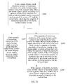
- FIG. 2a is a schematic flowchart of a mains supply method according to an embodiment of the present invention, and specifically includes the following steps:
- An example is used to illustrate a relationship between the detected quantity of remaining electricity of the backup mains supply system, the preset value, and the maximum quantity of backup electricity of the backup mains supply system.
- a second preset value accounts for 60% of the maximum quantity of backup electricity of the backup mains supply system, and if the detected quantity of remaining electricity of the backup mains supply system accounts for 20% of the maximum quantity of backup electricity of the backup mains supply system, the quantity of remaining electricity of the backup mains supply system is less than the preset value.
- the critical load refers to a load that needs to work uninterruptedly, that cannot have an electricity failure in midway, or whose electricity failure in midway may cause a huge loss, for example, a data center and a server room. These loads need to work uninterruptedly and cannot have an electricity failure in midway. If an electricity failure occurs in midway, a great amount of data information may be lost due to lack of timely storage, which seriously affects people's daily work and life.
- a mains supply system which load is considered as a critical load and which load is not considered as a critical load is determined by a person skilled in the art according to the foregoing principles and an empirical value, and the identification of a critical load is relative, and a purpose is to reduce, as much as possible, adverse impact resulted from the mains failure.
- a data center is considered as a critical load; but in another mains supply system, a data center is not considered as a critical load.
- the time T is determined by a person skilled in the art with reference to historical time of a mains failure, and this value is specifically an empirical value.
- the preset value may be determined according to the critical load and the time T.
- the quantity of feedable electricity of the electric vehicle of the mains supply system refers to the maximum quantity of electricity that can be provided for the critical load by all electric vehicles that use the mains as a charging source and are being charged, that is, the quantity of feedable electricity of the electric vehicle of the mains supply system refers to a sum of a maximum quantity of electricity that can be provided for the critical load by each electric vehicle that uses the mains as a charging source and is being charged, where the maximum quantity of electricity that can be provided for the critical load by each electric vehicle is a difference between a quantity of electricity that is actually stored by the electric vehicle at present and a minimum quantity of to be consumed electricity preset for the electric vehicle.
- the one or more electric vehicles that can provide a quantity of feedable electricity and the backup mains supply system are controlled to jointly supply electricity to the critical load.
- all the electric vehicles that can provide a quantity of feedable electricity and the backup mains supply system are controlled to jointly supply electricity to the critical load.
- controlling one or more electric vehicles that can provide a quantity of feedable electricity to supply electricity to the critical load may be controlling the one or more electric vehicles that can provide a quantity of feedable electricity to supply electricity to the critical load, and may also be firstly controlling the one or more electric vehicles that can provide a quantity of feedable electricity to supply electricity to the backup mains supply system, and then controlling the backup mains supply system to supply electricity to the critical load.
- Either of the two solutions can implement the present invention; however, for ease of implementation based on technologies, the latter is a preferred solution.
- controlling the backup mains supply system to supply electricity to the critical load may take place before or after the detecting whether a quantity of feedable electricity of an electric vehicle of the mains supply system is greater than zero, or take place concurrently with the detecting action.
- a mains supply method shown in FIG. 2b further includes a step S207, where if the quantity of remaining electricity of the backup mains supply system is greater than the preset value, the backup mains supply system is controlled to supply electricity to the critical load.
- the backup mains supply system can independently support the critical load to work for a time T, because the backup mains supply system can independently support the critical load to work for a time T, the electric vehicle of the mains supply system does not need to assist the backup mains supply system in supplying electricity to the critical load to support the critical load to work for the time T.
- a quantity of backup electricity of a backup mains supply system is greater than a preset value, where if the quantity of backup electricity of the backup mains supply system is greater than or equal to the preset value, the backup mains supply system can independently support a critical load of the backup mains supply system to work for a time T; on the contrary, if the quantity of backup electricity of the backup mains supply system is less than the preset value, the backup mains supply system cannot independently support the critical load of the backup mains supply system to work for the time T, and then it is further detected whether a quantity of feedable electricity of an electric vehicle of a mains supply system is greater than zero, where if the quantity of feedable electricity of the electric vehicle of the mains supply system is greater than zero, the electric vehicle and the backup mains supply system are controlled to jointly supply electricity to the critical load, so that after a mains failure, the critical load is supported to work properly
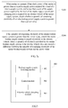
- FIG. 2c is a schematic flowchart of another mains supply method according to an embodiment of the present invention. Specifically, a charging control method of the electric vehicle includes the following steps:
- the threshold power of the mains refers to maximum power that can be afforded by the mains.
- the electricity supply power required by the load of the mains supply system refers to a sum of electricity supply power required by each load that uses the mains as an electricity supply source and is working and therefore needs the mains to supply electricity.
- the charging power required by the electric vehicle of the mains supply system refers to a sum of charging power required by each electric vehicle that uses the mains as a charging source and is being charged, and the charging power required by the electric vehicle of the mains supply system depends on a quantity of current to-be-charged electric vehicles of the mains supply system and charging power required by each to-be-charged electric vehicle.
- the threshold power of the mains is less than the sum of the electricity supply power required by the load of the mains supply system and the charging power required by the electric vehicle of the mains supply system; or if the quantity of the to-be-charged electric vehicles is not large, but many of the to-be-charged electric vehicles require fast charging, that is, the required charging power is relatively high, the threshold power of the mains may be less than charging power required by an electric vehicle charging system.
- the threshold power of the mains is greater than or equal to the electricity supply power required by the load of the mains supply system, and is less than the sum of the electricity supply power required by the load of the mains supply system and the charging power required by the electric vehicle of the mains supply system, that is, the mains can satisfy an electricity demand of the load of the mains supply system, but cannot satisfy the electricity demand of the load of the mains supply system and that of the electric vehicle of the mains supply system at the same time.
- it is required to detect whether the quantity of remaining electricity of the backup mains supply system is greater than the preset value, so as to determine whether to enable the backup mains supply system, which is configured to compensate, to some extent, for an insufficient part in the supply to the electric vehicle by the mains.
- the preset value is a preset value for enabling the backup mains supply system to supply electricity to the electric vehicle of the mains supply system.
- a core function of the backup mains supply system is to supply electricity to a critical load of the mains supply system upon a mains failure, so that after the mains failure, the critical load is kept working properly for the time T so as to wait for the mains to restore. Therefore, when the mains is normal, the quantity of remaining electricity of the backup mains supply system must be greater than or equal to the preset value, so as to prevent a mains failure.
- the mains when the mains is normal and the mains can supply only the electricity demand of the load of the mains supply system, but cannot supply the electricity demand of the load of the mains supply system and an electricity supply demand of the electric vehicle of the mains supply system at the same time, it is required to control the backup mains supply system to supply electricity to the electric vehicle, so that when an insufficient part in electricity supply of the mains is compensated to some extent, the quantity of electricity provided by the backup mains supply system to the electric vehicle does not exceed a difference between the quantity of remaining electricity of the backup mains supply system and the preset value.
- the mains supply method further includes: if the quantity of remaining electricity of the backup mains supply system is less than or equal to the preset value, reducing a quantity of charging electricity required by the electric vehicle, so that a quantity of supplied electricity of the mains can afford a quantity of supplied electricity required by the load of the mains supply system and the quantity of charging electricity required by the electric vehicle of the mains supply system.
- the backup mains supply system does not supply electricity to the electric vehicle of the mains supply system, and accordingly, the quantity of charging electricity required by the electric vehicle of the backup mains supply system needs to be reduced, so that the quantity of supplied electricity of the mains can afford the quantity of supplied electricity required by the load of the mains supply system and the quantity of charging electricity required by the electric vehicle of the mains supply system.
- the mains supply method further includes: controlling the mains to charge the backup mains supply system, and when the quantity of remaining electricity of the backup mains supply system reaches a maximum quantity of backup electricity of the backup mains supply system, stopping charging (not shown in the figure).
- the solution includes: detecting whether a quantity of remaining electricity of a backup mains supply system is greater than a preset value, and when the quantity of remaining electricity of the backup mains supply system is greater than the preset value, controlling the backup mains supply system to supply electricity to the electric vehicle, so as to compensate, to some extent, for insufficiency of electricity supply provided by the mains, thereby ensuring stability of electricity supply of the mains.
- FIG. 3 is a schematic structural diagram of a mains supply apparatus 300 according to an embodiment of the present invention.
- the mains supply apparatus is configured to implement a function of Embodiment 1, and specifically, the apparatus 300 includes: a backup supply system detecting module 302, a control module 303, and an electric vehicle detecting module 304.
- the backup supply system detecting module 302 is configured to detect, upon a mains failure, whether a quantity of remaining electricity of a backup mains supply system is less than a preset value, where the preset value is preset according to a quantity of electricity required for a critical load of a mains supply system to work properly for a time T2, and the preset value is less than a maximum quantity of backup electricity of the backup mains supply system.
- An example is used to illustrate a relationship between the detected quantity of remaining electricity of the backup mains supply system, the preset value, and the maximum quantity of backup electricity of the backup mains supply system.
- a second preset value accounts for 60% of the maximum quantity of backup electricity of the backup mains supply system, and if the detected quantity of remaining electricity of the backup mains supply system accounts for 20% of the maximum quantity of backup electricity of the backup mains supply system, the quantity of remaining electricity of the backup mains supply system is less than the preset value.
- the critical load refers to a load that needs to work uninterruptedly, that cannot have an electricity failure in midway, or whose electricity failure in midway may cause a huge loss, for example, a data center and a server room. These loads need to work uninterruptedly and cannot have an electricity failure in midway. If an electricity failure occurs in midway, a great amount of data information may be lost due to lack of timely storage, which seriously affects people's daily work and life.
- a mains supply system which load is considered as a critical load and which load is not considered as a critical load is determined by a person skilled in the art according to the foregoing principles and an empirical value, and the identification of a critical load is relative, and a purpose is to reduce, as much as possible, adverse impact resulted from the mains failure.
- a data center is considered as a critical load; but in another mains supply system, a data center is not considered as a critical load.
- the time T is determined by a person skilled in the art with reference to historical time of a mains failure, and this value is specifically an empirical value.
- the preset value may be determined according to the critical load and the time T.
- the control module 303 is configured to control, when the quantity of remaining electricity of the backup mains supply system is less than the preset value, the backup mains supply system to supply electricity to the critical load.
- the electric vehicle detecting module 304 is configured to detect, when the quantity of remaining electricity of the backup mains supply system is less than the preset value, whether a quantity of feedable electricity of an electric vehicle of the mains supply system is greater than zero, where the quantity of feedable electricity of the electric vehicle of the mains supply system refers to a maximum quantity of electricity that can be provided for the critical load by all electric vehicles that use mains as a charging source and are being charged.
- the quantity of feedable electricity of the electric vehicle of the mains supply system refers to the maximum quantity of electricity that can be provided for the critical load by all electric vehicles that use the mains as a charging source and are being charged, that is, the quantity of feedable electricity of the electric vehicle of the mains supply system refers to a sum of a maximum quantity of electricity that can be provided for the critical load by each electric vehicle that uses the mains as a charging source and is being charged, where the maximum quantity of electricity that can be provided for the critical load by each electric vehicle is a difference between a quantity of electricity that is actually stored by the electric vehicle at present and a minimum quantity of to be consumed electricity preset for the electric vehicle.
- the control module 303 is further configured to control, if the quantity of feedable electricity of the electric vehicle of the mains supply system is greater than zero, one or more electric vehicles that can provide a quantity of feedable electricity to supply electricity to the critical load.
- the one or more electric vehicles that can provide a quantity of feedable electricity and the backup mains supply system are controlled to jointly supply electricity to the critical load.
- all the electric vehicles that can provide a quantity of feedable electricity and the backup mains supply system are controlled to jointly supply electricity to the critical load.
- That the control module 303 controls the backup mains supply system to supply electricity to the critical load may take place before or after the detecting whether a quantity of feedable electricity of an electric vehicle of the mains supply system is greater than zero, or take place concurrently with the detecting action.
- control module 303 is specifically configured to control the one or more electric vehicles that can provide a quantity of feedable electricity to supply electricity to the backup mains supply system, and control the backup mains supply system to supply electricity to the critical load; or control the one or more electric vehicles that can provide a quantity of feedable electricity to directly supply electricity to the critical load.
- control module 303 is further configured to control, when the quantity of remaining electricity of the backup mains supply system is greater than the preset value, the backup mains supply system to supply electricity to the critical load.
- a quantity of backup electricity of a backup mains supply system is greater than a preset value, where if the quantity of backup electricity of the backup mains supply system is greater than or equal to the preset value, the backup mains supply system can independently support a critical load of the backup mains supply system to work for a time T; on the contrary, if the quantity of backup electricity of the backup mains supply system is less than the preset value, the backup mains supply system cannot independently support the critical load of the backup mains supply system to work for the time T, and then it is further detected whether a quantity of feedable electricity of an electric vehicle of a mains supply system is greater than zero, where if the quantity of feedable electricity of the electric vehicle of the mains supply system is greater than zero, one or more electric vehicles that can provide a quantity of feedable electricity and the backup mains supply system are controlled to jointly supply electricity to the critical load, so that after a
- the backup supply system detecting module 302 is further configured to: when the mains works properly, if threshold power of the mains is greater than or equal to electricity supply power required by loads of the mains supply system, and the threshold power of the mains is less than a sum of the electricity supply power required by the loads of the mains supply system and charging power required by the electric vehicle of the mains supply system, detect whether the quantity of remaining electricity of the backup mains supply system is greater than the second preset value.
- the threshold power of the mains refers to maximum power that can be afforded by the mains.
- the electricity supply power required by the load of the mains supply system refers to a sum of electricity supply power required by each load that uses the mains as an electricity supply source and is working and therefore needs the mains to supply electricity.
- the charging power required by the electric vehicle of the mains supply system refers to a sum of charging power required by each electric vehicle that uses the mains as a charging source and is being charged, and the charging power required by the electric vehicle of the mains supply system depends on a quantity of current to-be-charged electric vehicles of the mains supply system and charging power required by each to-be-charged electric vehicle.
- the threshold power of the mains is less than the sum of the electricity supply power required by the load of the mains supply system and the charging power required by the electric vehicle of the mains supply system; or if the quantity of the to-be-charged electric vehicles is not large, but many of the to-be-charged electric vehicles require fast charging, that is, the required charging power is relatively high, the threshold power of the mains may be less than charging power required by an electric vehicle charging system.
- the threshold power of the mains is greater than or equal to the electricity supply power required by the load of the mains supply system, and is less than the sum of the electricity supply power required by the load of the mains supply system and the charging power required by the electric vehicle of the mains supply system, that is, the mains can satisfy an electricity demand of the load of the mains supply system, but cannot satisfy the electricity demand of the load of the mains supply system and that of the electric vehicle of the mains supply system at the same time.
- it is required to detect whether the quantity of remaining electricity of the backup mains supply system is greater than the preset value, so as to determine whether to enable the backup mains supply system, which is configured to compensate, to some extent, for an insufficient part in the supply to the electric vehicle by the mains.
- the preset value is a preset value for enabling the backup mains supply system to supply electricity to the electric vehicle of the mains supply system.
- the control module 303 is further configured to control, if the quantity of remaining electricity of the backup mains supply system is greater than the second preset value, the backup mains supply system to supply electricity to the electric vehicle, where a quantity of electricity provided by the backup mains supply system to the electric vehicle does not exceed a difference between the quantity of remaining electricity of the backup mains supply system and the second preset value.
- a core function of the backup mains supply system is to supply electricity to a critical load of the mains supply system upon a mains failure, so that after the mains failure, the critical load is kept working properly for the time T so as to wait for the mains to restore. Therefore, when the mains is normal, the quantity of remaining electricity of the backup mains supply system must be greater than or equal to the preset value, so as to prevent a mains failure.
- the mains when the mains is normal and the mains can supply only the electricity demand of the load of the mains supply system, but cannot supply the electricity demand of the load of the mains supply system and an electricity supply demand of the electric vehicle of the mains supply system at the same time, it is required to control the backup mains supply system to supply electricity to the electric vehicle, so that when an insufficient part in electricity supply of the mains is compensated to some extent, the quantity of electricity provided by the backup mains supply system to the electric vehicle does not exceed a difference between the quantity of remaining electricity of the backup mains supply system and the preset value.
- control module 303 is further configured to: if the quantity of remaining electricity of the backup mains supply system is less than or equal to the second preset value, reduce a quantity of charging electricity required by the electric vehicle, so that a quantity of supplied electricity of the mains can afford a quantity of supplied electricity required by the load of the mains supply system and the quantity of charging electricity required by the electric vehicle of the mains supply system.
- the backup mains supply system does not supply electricity to the electric vehicle of the mains supply system, and accordingly, the quantity of charging electricity required by the electric vehicle of the backup mains supply system needs to be reduced, so that the quantity of supplied electricity of the mains can afford the quantity of supplied electricity required by the load of the mains supply system and the quantity of charging electricity required by the electric vehicle of the mains supply system.
- the mains supply method further includes: controlling the mains to charge the backup mains supply system, and when the quantity of remaining electricity of the backup mains supply system reaches a maximum quantity of backup electricity of the backup mains supply system, stopping charging (not shown in the figure).
- the solution includes: detecting whether a quantity of remaining electricity of a backup mains supply system is greater than a preset value, and when the quantity of remaining electricity of the backup mains supply system is greater than the preset value, controlling the backup mains supply system to supply electricity to the electric vehicle, so as to compensate, to some extent, for insufficiency of electricity supply provided by the mains, thereby ensuring stability of electricity supply of the mains.
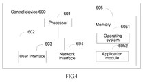
- FIG. 4 is a control device 600 provided by an embodiment of the present invention.
- a control system shown in FIG. 1 may be specifically embodied in the control device 600, where the control device 600 may include at least one processor 601, for example, a CPU, at least one network interface 604, for example, a physical network interface card or another user interface 603, storage memory 605, and at least one communications bus 602.
- processor 601 for example, a CPU
- network interface 604 for example, a physical network interface card or another user interface 603, storage memory 605, and at least one communications bus 602.
- the communications bus 602 is configured to implement a connection and communication between these components.
- the network interface 604 is configured to implement the connection and communication between the control device 600 and a network, for example, the control device 600 connects to devices such as the physical network interface card and/or a physical switch by using the network interface 604, so as to receive data sent by other network devices.
- the user interface 603 may include a display, a keyboard or other clicking devices, for example, a mouse, a trackball (trackball), a touch panel, or a touch screen.
- the memory 605 may include a Random Access Memory (RAM for short, Random Access Memory), and may further include a non-volatile memory (non-volatile memory), for example, at least one magnetic disk storage.
- the memory 605 may further include at least one storage apparatus disposed far from the foregoing processor 601.
- the memory 605 stores the following elements: an executable module or data structure, or their subsets, or their extended sets: an operating system 6051, including various system programs, configured to implement various basic services and process hardware-based tasks; and an application module 6052, including various application programs, configured to implement various application services; where the application module 6052 includes but is not limited to various units related to data exchange with a virtual machine, such as an acquiring unit, a determining unit, and a transceiver unit.
- the processor 601 receives, by using the network interface 604, data used to indicate a mains failure, then the processor 601 is configured to detect whether a quantity of remaining electricity of a backup mains supply system is less than a preset value, where the preset value is preset according to a quantity of electricity required for a critical load of a mains supply system to work properly for a time T, and the preset value is less than a maximum quantity of backup electricity of the backup mains supply system; when the quantity of remaining electricity of the backup mains supply system is less than the preset value, control the backup mains supply system to supply electricity to the critical load, and detect whether a quantity of feedable electricity of an electric vehicle of the mains supply system is greater than zero, where the quantity of feedable electricity of the electric vehicle of the mains supply system refers to a maximum quantity of electricity that can be provided for the critical load by all electric vehicles that use the mains as a charging source and are being charged; and if the quantity of feedable electricity of the electric vehicle of the mains supply system
- the processor 601 is further configured to, when the quantity of remaining electricity of the backup mains supply system is greater than or equal to the preset value, control the backup mains supply system to supply electricity to the critical load.
- That the processor 601 is further configured to control one or more electric vehicles that can provide a quantity of feedable electricity to supply electricity to the critical load may specifically be that: the processor 601 first controls the one or more electric vehicles that can provide a quantity of feedable electricity to supply electricity to the backup mains supply system, and then controls the backup mains supply system to supply electricity to the critical load; or controls the one or more electric vehicles that can provide a quantity of feedable electricity to directly supply electricity to the critical load.
- the processor 601 receives data used to indicate that the mains works properly, and if threshold power of the mains is greater than or equal to electricity supply power required by a load of the mains supply system, and the threshold power of the mains is less than a sum of the electricity supply power required by the load of the mains supply system and charging power required by the electric vehicle of the mains supply system, it is detected whether the quantity of remaining electricity of the backup mains supply system is greater than the preset value, where the load of the main electricity supply system includes the critical load; and if the quantity of remaining electricity of the backup mains supply system is greater than the preset value, the backup mains supply system is controlled to supply electricity to the one or more electric vehicles, where a quantity of electricity provided by the backup mains supply system for the one or more electric vehicles does not exceed a difference between the quantity of remaining electricity of the backup mains supply system and the preset value.
- the processor 604 is further configured to: if the quantity of remaining electricity of the backup mains supply system is less than or equal to the preset value, reduce a quantity of charging electricity required by the electric vehicle, so that a quantity of supplied electricity of the mains can afford a quantity of supplied electricity required by the load of the mains supply system and the quantity of charging electricity required by the electric vehicle of the mains supply system.
- the control device configured to, when a mains failure occurs and a quantity of remaining electricity of a backup mains supply system is insufficient, control an electric vehicle to supply electricity to a critical load, so as to prolong a working time The critical load as much as possible; when mains are normal but the mains can only satisfy a demand of a load and cannot satisfy a charging demand of the electric vehicle at the same time, in a case in which the quantity of remaining electricity maintaining a backup mains supply system is enough for supporting the critical load to work properly for a time T upon a mains failure, control the backup mains supply system to charge the electric vehicle, so as to satisfy the charging demand of the electric vehicle as much as possible.
- Controlling a mains circuit by using the control device provided by this embodiment of the present invention benefits proper resource scheduling and facilitates normal life to the most extent.
- a person of ordinary skill in the art may be aware that, in combination with the examples described in the embodiments disclosed in this specification, units and algorithm steps may be implemented by electronic hardware or a combination of computer software and electronic hardware. Whether the functions are performed by hardware or software depends on particular applications and design constraint conditions of the technical solutions. A person skilled in the art may use different methods to implement the described functions for each particular application, but it should not be considered that the implementation goes beyond the scope of the present invention.
- the disclosed system, apparatus, and method may be implemented in other manners.
- the described apparatus embodiment is merely exemplary.
- the unit division is merely logical function division and may be other division in actual implementation.
- a plurality of units or components may be combined or integrated into another system, or some features may be ignored or not performed.
- the displayed or discussed mutual couplings or direct couplings or communication connections may be implemented through some interfaces.
- the indirect couplings or communication connections between the apparatuses or units may be implemented in electronic, mechanical, or other forms.
- the units described as separate parts may or may not be physically separate, and parts displayed as units may or may not be physical units, may be located in one position, or may be distributed on a plurality of network units. Apart or all of the units may be selected according to actual needs to achieve the objectives of the solutions of the embodiments.
- functional units in the embodiments of the present invention may be integrated into one processing unit, or each of the units may exist alone physically, or two or more units are integrated into one unit.
- the functions When the functions are implemented in the form of a software functional unit and sold or used as an independent product, the functions may be stored in a computer-readable storage medium. Based on such an understanding, the technical solutions of the present invention essentially, or the part contributing to the prior art, or a part of the technical solutions may be implemented in a form of a software product.
- the software product is stored in a storage medium and includes several instructions for instructing a computer device (which may be a personal computer, a server, or a network device) or a processor to perform all or a part of the steps of the methods described in the embodiments of the present invention.
- the foregoing storage medium includes: any medium that can store program code, such as a USB flash drive, a removable hard disk, a read-only memory (ROM, Read-Only Memory), a random access memory (RAM, Random Access Memory), a magnetic disk, or an optical disc.
- program code such as a USB flash drive, a removable hard disk, a read-only memory (ROM, Read-Only Memory), a random access memory (RAM, Random Access Memory), a magnetic disk, or an optical disc.
Landscapes
- Engineering & Computer Science (AREA)
- Power Engineering (AREA)
- Transportation (AREA)
- Mechanical Engineering (AREA)
- Business, Economics & Management (AREA)
- Emergency Management (AREA)
- Charge And Discharge Circuits For Batteries Or The Like (AREA)
- Stand-By Power Supply Arrangements (AREA)
- Electric Propulsion And Braking For Vehicles (AREA)
Applications Claiming Priority (2)
| Application Number | Priority Date | Filing Date | Title |
|---|---|---|---|
| CN201410229059.8A CN105305596B (zh) | 2014-05-28 | 2014-05-28 | 一种市电供电方法和装置 |
| PCT/CN2015/072671 WO2015180514A1 (fr) | 2014-05-28 | 2015-02-10 | Procédé et dispositif d'alimentation électrique commerciale |
Publications (3)
| Publication Number | Publication Date |
|---|---|
| EP2993759A1 true EP2993759A1 (fr) | 2016-03-09 |
| EP2993759A4 EP2993759A4 (fr) | 2016-11-02 |
| EP2993759B1 EP2993759B1 (fr) | 2019-04-10 |
Family
ID=54698046
Family Applications (1)
| Application Number | Title | Priority Date | Filing Date |
|---|---|---|---|
| EP15794443.0A Active EP2993759B1 (fr) | 2014-05-28 | 2015-02-10 | Procédé et dispositif d'alimentation électrique commerciale |
Country Status (4)
| Country | Link |
|---|---|
| US (1) | US20160107533A1 (fr) |
| EP (1) | EP2993759B1 (fr) |
| CN (1) | CN105305596B (fr) |
| WO (1) | WO2015180514A1 (fr) |
Families Citing this family (6)
| Publication number | Priority date | Publication date | Assignee | Title |
|---|---|---|---|---|
| CN107128185B (zh) * | 2016-02-29 | 2020-06-16 | 华为技术有限公司 | 一种电机驱动装置及电动汽车 |
| CN106026346B (zh) * | 2016-05-16 | 2019-05-24 | 国网北京市电力公司 | 应急供电方法和装置及系统 |
| CN106696748B (zh) * | 2017-01-25 | 2019-06-28 | 华为技术有限公司 | 一种充电桩系统 |
| CN110970991A (zh) * | 2018-09-30 | 2020-04-07 | 上海华为技术有限公司 | 一种能量控制方法及能量控制系统 |
| CN112638700B (zh) * | 2020-04-15 | 2021-11-30 | 华为技术有限公司 | 一种充放电切换装置、方法及双向充电系统 |
| US11817701B2 (en) | 2021-01-29 | 2023-11-14 | Eaton Intelligent Power Limited | Multi-port split-phase power system |
Family Cites Families (13)
| Publication number | Priority date | Publication date | Assignee | Title |
|---|---|---|---|---|
| US20100017045A1 (en) * | 2007-11-30 | 2010-01-21 | Johnson Controls Technology Company | Electrical demand response using energy storage in vehicles and buildings |
| US8106627B1 (en) * | 2008-12-15 | 2012-01-31 | Comverge, Inc. | Method and system for co-operative charging of electric vehicles |
| EP2325970A3 (fr) * | 2009-11-19 | 2015-01-21 | Samsung SDI Co., Ltd. | Système de gestion d'énergie et système de stockage d'énergie raccordée au réseau incluant le système de gestion d'énergie |
| EP2583366A1 (fr) * | 2010-06-16 | 2013-04-24 | Rolls-Royce PLC | Système de recharge pour un véhicule électrique |
| CN102437584A (zh) * | 2010-10-27 | 2012-05-02 | 上海市电力公司 | 智能电网中应用电动汽车作为移动储能设备的系统和方法 |
| JP5273186B2 (ja) * | 2011-03-11 | 2013-08-28 | 株式会社デンソー | 車載電力供給装置および電力供給システム |
| JP6062162B2 (ja) * | 2012-06-07 | 2017-01-18 | シャープ株式会社 | 充放電装置 |
| CN102868205B (zh) * | 2012-08-28 | 2015-03-25 | 中国电力科学研究院 | 电动汽车与可再生能源的互补系统 |
| US10693294B2 (en) * | 2012-09-26 | 2020-06-23 | Stem, Inc. | System for optimizing the charging of electric vehicles using networked distributed energy storage systems |
| CN203423531U (zh) * | 2013-09-04 | 2014-02-05 | 厦门多科莫太阳能科技有限公司 | 光电建筑微电网管理系统 |
| CN103606994A (zh) * | 2013-10-21 | 2014-02-26 | 清华大学 | 供电系统、供电控制方法及供电控制器 |
| CN103545844A (zh) * | 2013-11-06 | 2014-01-29 | 国家电网公司 | 一种以混合动力汽车为备用电源的微电网系统 |
| AT515259A1 (de) * | 2014-01-02 | 2015-07-15 | Omicron Electronics Gmbh | Vorrichtung und Verfahren zur Notstromversorgung wenigstens eines elektrischen Verbrauchers |
-
2014
- 2014-05-28 CN CN201410229059.8A patent/CN105305596B/zh active Active
-
2015
- 2015-02-10 WO PCT/CN2015/072671 patent/WO2015180514A1/fr active Application Filing
- 2015-02-10 EP EP15794443.0A patent/EP2993759B1/fr active Active
- 2015-12-28 US US14/980,430 patent/US20160107533A1/en not_active Abandoned
Also Published As
| Publication number | Publication date |
|---|---|
| WO2015180514A1 (fr) | 2015-12-03 |
| US20160107533A1 (en) | 2016-04-21 |
| CN105305596B (zh) | 2019-03-08 |
| CN105305596A (zh) | 2016-02-03 |
| EP2993759A4 (fr) | 2016-11-02 |
| EP2993759B1 (fr) | 2019-04-10 |
Similar Documents
| Publication | Publication Date | Title |
|---|---|---|
| US20160107533A1 (en) | Mains Supply Method and Apparatus | |
| US10003200B2 (en) | Decentralized module-based DC data center | |
| US11314311B2 (en) | Battery runtime and performance management based upon presence detection | |
| US10466729B2 (en) | Power supply system, power management, apparatus, power management method, and power management program | |
| WO2021175215A1 (fr) | Procédé et système d'alimentation électrique, dispositif d'alimentation électrique et support de stockage | |
| US20210208650A1 (en) | Systems and methods for graceful termination of applications in response to power event | |
| US9727104B2 (en) | Various PSUs adaptive server and method | |
| RU2669004C2 (ru) | Способ и устройство управления напряжением постоянного тока | |
| US10230263B2 (en) | Adaptive power availability controller | |
| CN103176585B (zh) | 调整电能消耗的装置及方法 | |
| CN110401240B (zh) | 供电方法及电子设备 | |
| US10476299B2 (en) | DC link voltage control | |
| US20210210956A1 (en) | Method and device for controlling distributed direct current power supply system | |
| CN111813209B (zh) | 一种电源组管控方法、系统、装置及计算机可读存储介质 | |
| JP5874773B2 (ja) | 情報処理装置 | |
| JP6253111B2 (ja) | 電力管理装置、電力管理方法および電力管理プログラム | |
| JP2012155425A (ja) | 無停電電源システム | |
| US11050294B1 (en) | Power supply shedding for power efficiency optimization | |
| CN109391027B (zh) | 数据中心供电系统节能控制方法及终端设备 | |
| JP7054991B2 (ja) | 直流集中電源システム | |
| JP6146459B2 (ja) | 情報処理装置 | |
| CN117081129A (zh) | 储能ups的控制方法、控制器、电源系统及存储介质 | |
| CN118054547A (zh) | 一种不间断电源装置的管理方法、系统、设备及存储介质 | |
| CN114884171A (zh) | 一种不间断电源的用电控制方法及系统 | |
| CN114123161A (zh) | 功率管理方法以及对应的控制装置和电气设备 |
Legal Events
| Date | Code | Title | Description |
|---|---|---|---|
| PUAI | Public reference made under article 153(3) epc to a published international application that has entered the european phase |
Free format text: ORIGINAL CODE: 0009012 |
|
| 17P | Request for examination filed |
Effective date: 20151124 |
|
| AK | Designated contracting states |
Kind code of ref document: A1 Designated state(s): AL AT BE BG CH CY CZ DE DK EE ES FI FR GB GR HR HU IE IS IT LI LT LU LV MC MK MT NL NO PL PT RO RS SE SI SK SM TR |
|
| AX | Request for extension of the european patent |
Extension state: BA ME |
|
| A4 | Supplementary search report drawn up and despatched |
Effective date: 20160930 |
|
| RIC1 | Information provided on ipc code assigned before grant |
Ipc: H02J 7/00 20060101ALI20160926BHEP Ipc: H02J 9/00 20060101ALI20160926BHEP Ipc: B60L 11/18 20060101ALI20160926BHEP Ipc: H02J 9/04 20060101ALI20160926BHEP Ipc: H02J 9/06 20060101AFI20160926BHEP |
|
| STAA | Information on the status of an ep patent application or granted ep patent |
Free format text: STATUS: EXAMINATION IS IN PROGRESS |
|
| DAX | Request for extension of the european patent (deleted) | ||
| 17Q | First examination report despatched |
Effective date: 20170822 |
|
| REG | Reference to a national code |
Ref country code: DE Ref legal event code: R079 Ref document number: 602015028165 Country of ref document: DE Free format text: PREVIOUS MAIN CLASS: H02J0009060000 Ipc: H02J0003320000 |
|
| RIC1 | Information provided on ipc code assigned before grant |
Ipc: H02J 9/00 20060101ALI20180725BHEP Ipc: H02J 9/04 20060101ALI20180725BHEP Ipc: H02J 3/32 20060101AFI20180725BHEP Ipc: H02J 9/06 20060101ALI20180725BHEP Ipc: B60L 11/18 20060101ALI20180725BHEP Ipc: H02J 7/00 20060101ALI20180725BHEP |
|
| GRAP | Despatch of communication of intention to grant a patent |
Free format text: ORIGINAL CODE: EPIDOSNIGR1 |
|
| STAA | Information on the status of an ep patent application or granted ep patent |
Free format text: STATUS: GRANT OF PATENT IS INTENDED |
|
| INTG | Intention to grant announced |
Effective date: 20180910 |
|
| GRAS | Grant fee paid |
Free format text: ORIGINAL CODE: EPIDOSNIGR3 |
|
| GRAA | (expected) grant |
Free format text: ORIGINAL CODE: 0009210 |
|
| STAA | Information on the status of an ep patent application or granted ep patent |
Free format text: STATUS: THE PATENT HAS BEEN GRANTED |
|
| AK | Designated contracting states |
Kind code of ref document: B1 Designated state(s): AL AT BE BG CH CY CZ DE DK EE ES FI FR GB GR HR HU IE IS IT LI LT LU LV MC MK MT NL NO PL PT RO RS SE SI SK SM TR |
|
| REG | Reference to a national code |
Ref country code: GB Ref legal event code: FG4D |
|
| REG | Reference to a national code |
Ref country code: CH Ref legal event code: EP Ref country code: AT Ref legal event code: REF Ref document number: 1119988 Country of ref document: AT Kind code of ref document: T Effective date: 20190415 |
|
| REG | Reference to a national code |
Ref country code: IE Ref legal event code: FG4D |
|
| REG | Reference to a national code |
Ref country code: DE Ref legal event code: R096 Ref document number: 602015028165 Country of ref document: DE |
|
| REG | Reference to a national code |
Ref country code: NL Ref legal event code: MP Effective date: 20190410 |
|
| REG | Reference to a national code |
Ref country code: LT Ref legal event code: MG4D |
|
| REG | Reference to a national code |
Ref country code: AT Ref legal event code: MK05 Ref document number: 1119988 Country of ref document: AT Kind code of ref document: T Effective date: 20190410 |
|
| PG25 | Lapsed in a contracting state [announced via postgrant information from national office to epo] |
Ref country code: NL Free format text: LAPSE BECAUSE OF FAILURE TO SUBMIT A TRANSLATION OF THE DESCRIPTION OR TO PAY THE FEE WITHIN THE PRESCRIBED TIME-LIMIT Effective date: 20190410 |
|
| PG25 | Lapsed in a contracting state [announced via postgrant information from national office to epo] |
Ref country code: SE Free format text: LAPSE BECAUSE OF FAILURE TO SUBMIT A TRANSLATION OF THE DESCRIPTION OR TO PAY THE FEE WITHIN THE PRESCRIBED TIME-LIMIT Effective date: 20190410 Ref country code: ES Free format text: LAPSE BECAUSE OF FAILURE TO SUBMIT A TRANSLATION OF THE DESCRIPTION OR TO PAY THE FEE WITHIN THE PRESCRIBED TIME-LIMIT Effective date: 20190410 Ref country code: HR Free format text: LAPSE BECAUSE OF FAILURE TO SUBMIT A TRANSLATION OF THE DESCRIPTION OR TO PAY THE FEE WITHIN THE PRESCRIBED TIME-LIMIT Effective date: 20190410 Ref country code: PT Free format text: LAPSE BECAUSE OF FAILURE TO SUBMIT A TRANSLATION OF THE DESCRIPTION OR TO PAY THE FEE WITHIN THE PRESCRIBED TIME-LIMIT Effective date: 20190910 Ref country code: AL Free format text: LAPSE BECAUSE OF FAILURE TO SUBMIT A TRANSLATION OF THE DESCRIPTION OR TO PAY THE FEE WITHIN THE PRESCRIBED TIME-LIMIT Effective date: 20190410 Ref country code: FI Free format text: LAPSE BECAUSE OF FAILURE TO SUBMIT A TRANSLATION OF THE DESCRIPTION OR TO PAY THE FEE WITHIN THE PRESCRIBED TIME-LIMIT Effective date: 20190410 Ref country code: NO Free format text: LAPSE BECAUSE OF FAILURE TO SUBMIT A TRANSLATION OF THE DESCRIPTION OR TO PAY THE FEE WITHIN THE PRESCRIBED TIME-LIMIT Effective date: 20190710 Ref country code: LT Free format text: LAPSE BECAUSE OF FAILURE TO SUBMIT A TRANSLATION OF THE DESCRIPTION OR TO PAY THE FEE WITHIN THE PRESCRIBED TIME-LIMIT Effective date: 20190410 |
|
| PG25 | Lapsed in a contracting state [announced via postgrant information from national office to epo] |
Ref country code: RS Free format text: LAPSE BECAUSE OF FAILURE TO SUBMIT A TRANSLATION OF THE DESCRIPTION OR TO PAY THE FEE WITHIN THE PRESCRIBED TIME-LIMIT Effective date: 20190410 Ref country code: BG Free format text: LAPSE BECAUSE OF FAILURE TO SUBMIT A TRANSLATION OF THE DESCRIPTION OR TO PAY THE FEE WITHIN THE PRESCRIBED TIME-LIMIT Effective date: 20190710 Ref country code: LV Free format text: LAPSE BECAUSE OF FAILURE TO SUBMIT A TRANSLATION OF THE DESCRIPTION OR TO PAY THE FEE WITHIN THE PRESCRIBED TIME-LIMIT Effective date: 20190410 Ref country code: GR Free format text: LAPSE BECAUSE OF FAILURE TO SUBMIT A TRANSLATION OF THE DESCRIPTION OR TO PAY THE FEE WITHIN THE PRESCRIBED TIME-LIMIT Effective date: 20190711 Ref country code: PL Free format text: LAPSE BECAUSE OF FAILURE TO SUBMIT A TRANSLATION OF THE DESCRIPTION OR TO PAY THE FEE WITHIN THE PRESCRIBED TIME-LIMIT Effective date: 20190410 |
|
| PG25 | Lapsed in a contracting state [announced via postgrant information from national office to epo] |
Ref country code: IS Free format text: LAPSE BECAUSE OF FAILURE TO SUBMIT A TRANSLATION OF THE DESCRIPTION OR TO PAY THE FEE WITHIN THE PRESCRIBED TIME-LIMIT Effective date: 20190810 Ref country code: AT Free format text: LAPSE BECAUSE OF FAILURE TO SUBMIT A TRANSLATION OF THE DESCRIPTION OR TO PAY THE FEE WITHIN THE PRESCRIBED TIME-LIMIT Effective date: 20190410 |
|
| REG | Reference to a national code |
Ref country code: DE Ref legal event code: R097 Ref document number: 602015028165 Country of ref document: DE |
|
| PG25 | Lapsed in a contracting state [announced via postgrant information from national office to epo] |
Ref country code: EE Free format text: LAPSE BECAUSE OF FAILURE TO SUBMIT A TRANSLATION OF THE DESCRIPTION OR TO PAY THE FEE WITHIN THE PRESCRIBED TIME-LIMIT Effective date: 20190410 Ref country code: DK Free format text: LAPSE BECAUSE OF FAILURE TO SUBMIT A TRANSLATION OF THE DESCRIPTION OR TO PAY THE FEE WITHIN THE PRESCRIBED TIME-LIMIT Effective date: 20190410 Ref country code: RO Free format text: LAPSE BECAUSE OF FAILURE TO SUBMIT A TRANSLATION OF THE DESCRIPTION OR TO PAY THE FEE WITHIN THE PRESCRIBED TIME-LIMIT Effective date: 20190410 Ref country code: CZ Free format text: LAPSE BECAUSE OF FAILURE TO SUBMIT A TRANSLATION OF THE DESCRIPTION OR TO PAY THE FEE WITHIN THE PRESCRIBED TIME-LIMIT Effective date: 20190410 Ref country code: SK Free format text: LAPSE BECAUSE OF FAILURE TO SUBMIT A TRANSLATION OF THE DESCRIPTION OR TO PAY THE FEE WITHIN THE PRESCRIBED TIME-LIMIT Effective date: 20190410 |
|
| PLBE | No opposition filed within time limit |
Free format text: ORIGINAL CODE: 0009261 |
|
| STAA | Information on the status of an ep patent application or granted ep patent |
Free format text: STATUS: NO OPPOSITION FILED WITHIN TIME LIMIT |
|
| PG25 | Lapsed in a contracting state [announced via postgrant information from national office to epo] |
Ref country code: IT Free format text: LAPSE BECAUSE OF FAILURE TO SUBMIT A TRANSLATION OF THE DESCRIPTION OR TO PAY THE FEE WITHIN THE PRESCRIBED TIME-LIMIT Effective date: 20190410 Ref country code: SM Free format text: LAPSE BECAUSE OF FAILURE TO SUBMIT A TRANSLATION OF THE DESCRIPTION OR TO PAY THE FEE WITHIN THE PRESCRIBED TIME-LIMIT Effective date: 20190410 |
|
| 26N | No opposition filed |
Effective date: 20200113 |
|
| PG25 | Lapsed in a contracting state [announced via postgrant information from national office to epo] |
Ref country code: TR Free format text: LAPSE BECAUSE OF FAILURE TO SUBMIT A TRANSLATION OF THE DESCRIPTION OR TO PAY THE FEE WITHIN THE PRESCRIBED TIME-LIMIT Effective date: 20190410 |
|
| PG25 | Lapsed in a contracting state [announced via postgrant information from national office to epo] |
Ref country code: SI Free format text: LAPSE BECAUSE OF FAILURE TO SUBMIT A TRANSLATION OF THE DESCRIPTION OR TO PAY THE FEE WITHIN THE PRESCRIBED TIME-LIMIT Effective date: 20190410 |
|
| REG | Reference to a national code |
Ref country code: CH Ref legal event code: PL |
|
| REG | Reference to a national code |
Ref country code: BE Ref legal event code: MM Effective date: 20200229 |
|
| PG25 | Lapsed in a contracting state [announced via postgrant information from national office to epo] |
Ref country code: MC Free format text: LAPSE BECAUSE OF FAILURE TO SUBMIT A TRANSLATION OF THE DESCRIPTION OR TO PAY THE FEE WITHIN THE PRESCRIBED TIME-LIMIT Effective date: 20190410 Ref country code: LU Free format text: LAPSE BECAUSE OF NON-PAYMENT OF DUE FEES Effective date: 20200210 |
|
| PG25 | Lapsed in a contracting state [announced via postgrant information from national office to epo] |
Ref country code: CH Free format text: LAPSE BECAUSE OF NON-PAYMENT OF DUE FEES Effective date: 20200229 Ref country code: LI Free format text: LAPSE BECAUSE OF NON-PAYMENT OF DUE FEES Effective date: 20200229 |
|
| PG25 | Lapsed in a contracting state [announced via postgrant information from national office to epo] |
Ref country code: IE Free format text: LAPSE BECAUSE OF NON-PAYMENT OF DUE FEES Effective date: 20200210 |
|
| PG25 | Lapsed in a contracting state [announced via postgrant information from national office to epo] |
Ref country code: BE Free format text: LAPSE BECAUSE OF NON-PAYMENT OF DUE FEES Effective date: 20200229 |
|
| PG25 | Lapsed in a contracting state [announced via postgrant information from national office to epo] |
Ref country code: MT Free format text: LAPSE BECAUSE OF FAILURE TO SUBMIT A TRANSLATION OF THE DESCRIPTION OR TO PAY THE FEE WITHIN THE PRESCRIBED TIME-LIMIT Effective date: 20190410 Ref country code: CY Free format text: LAPSE BECAUSE OF FAILURE TO SUBMIT A TRANSLATION OF THE DESCRIPTION OR TO PAY THE FEE WITHIN THE PRESCRIBED TIME-LIMIT Effective date: 20190410 |
|
| PG25 | Lapsed in a contracting state [announced via postgrant information from national office to epo] |
Ref country code: MK Free format text: LAPSE BECAUSE OF FAILURE TO SUBMIT A TRANSLATION OF THE DESCRIPTION OR TO PAY THE FEE WITHIN THE PRESCRIBED TIME-LIMIT Effective date: 20190410 |
|
| PGFP | Annual fee paid to national office [announced via postgrant information from national office to epo] |
Ref country code: FR Payment date: 20231229 Year of fee payment: 10 |
|
| PGFP | Annual fee paid to national office [announced via postgrant information from national office to epo] |
Ref country code: DE Payment date: 20231229 Year of fee payment: 10 Ref country code: GB Payment date: 20240108 Year of fee payment: 10 |