EP2993751A1 - Method and device for controlling an adjusting device of a motor vehicle - Google Patents
Method and device for controlling an adjusting device of a motor vehicle Download PDFInfo
- Publication number
- EP2993751A1 EP2993751A1 EP15180934.0A EP15180934A EP2993751A1 EP 2993751 A1 EP2993751 A1 EP 2993751A1 EP 15180934 A EP15180934 A EP 15180934A EP 2993751 A1 EP2993751 A1 EP 2993751A1
- Authority
- EP
- European Patent Office
- Prior art keywords
- force
- speed
- setpoint
- drive
- case
- Prior art date
- Legal status (The legal status is an assumption and is not a legal conclusion. Google has not performed a legal analysis and makes no representation as to the accuracy of the status listed.)
- Granted
Links
Images


Classifications
-
- F—MECHANICAL ENGINEERING; LIGHTING; HEATING; WEAPONS; BLASTING
- F02—COMBUSTION ENGINES; HOT-GAS OR COMBUSTION-PRODUCT ENGINE PLANTS
- F02D—CONTROLLING COMBUSTION ENGINES
- F02D45/00—Electrical control not provided for in groups F02D41/00 - F02D43/00
-
- H—ELECTRICITY
- H02—GENERATION; CONVERSION OR DISTRIBUTION OF ELECTRIC POWER
- H02H—EMERGENCY PROTECTIVE CIRCUIT ARRANGEMENTS
- H02H7/00—Emergency protective circuit arrangements specially adapted for specific types of electric machines or apparatus or for sectionalised protection of cable or line systems, and effecting automatic switching in the event of an undesired change from normal working conditions
- H02H7/08—Emergency protective circuit arrangements specially adapted for specific types of electric machines or apparatus or for sectionalised protection of cable or line systems, and effecting automatic switching in the event of an undesired change from normal working conditions for dynamo-electric motors
- H02H7/085—Emergency protective circuit arrangements specially adapted for specific types of electric machines or apparatus or for sectionalised protection of cable or line systems, and effecting automatic switching in the event of an undesired change from normal working conditions for dynamo-electric motors against excessive load
- H02H7/0851—Emergency protective circuit arrangements specially adapted for specific types of electric machines or apparatus or for sectionalised protection of cable or line systems, and effecting automatic switching in the event of an undesired change from normal working conditions for dynamo-electric motors against excessive load for motors actuating a movable member between two end positions, e.g. detecting an end position or obstruction by overload signal
-
- B—PERFORMING OPERATIONS; TRANSPORTING
- B60—VEHICLES IN GENERAL
- B60J—WINDOWS, WINDSCREENS, NON-FIXED ROOFS, DOORS, OR SIMILAR DEVICES FOR VEHICLES; REMOVABLE EXTERNAL PROTECTIVE COVERINGS SPECIALLY ADAPTED FOR VEHICLES
- B60J7/00—Non-fixed roofs; Roofs with movable panels, e.g. rotary sunroofs
- B60J7/02—Non-fixed roofs; Roofs with movable panels, e.g. rotary sunroofs of sliding type, e.g. comprising guide shoes
- B60J7/04—Non-fixed roofs; Roofs with movable panels, e.g. rotary sunroofs of sliding type, e.g. comprising guide shoes with rigid plate-like element or elements, e.g. open roofs with harmonica-type folding rigid panels
- B60J7/057—Driving or actuating arrangements e.g. manually operated levers or knobs
- B60J7/0573—Driving or actuating arrangements e.g. manually operated levers or knobs power driven arrangements, e.g. electrical
-
- B—PERFORMING OPERATIONS; TRANSPORTING
- B62—LAND VEHICLES FOR TRAVELLING OTHERWISE THAN ON RAILS
- B62D—MOTOR VEHICLES; TRAILERS
- B62D5/00—Power-assisted or power-driven steering
- B62D5/04—Power-assisted or power-driven steering electrical, e.g. using an electric servo-motor connected to, or forming part of, the steering gear
- B62D5/0457—Power-assisted or power-driven steering electrical, e.g. using an electric servo-motor connected to, or forming part of, the steering gear characterised by control features of the drive means as such
- B62D5/0481—Power-assisted or power-driven steering electrical, e.g. using an electric servo-motor connected to, or forming part of, the steering gear characterised by control features of the drive means as such monitoring the steering system, e.g. failures
- B62D5/0487—Power-assisted or power-driven steering electrical, e.g. using an electric servo-motor connected to, or forming part of, the steering gear characterised by control features of the drive means as such monitoring the steering system, e.g. failures detecting motor faults
Definitions
- the invention relates to a method for controlling an adjusting device of a motor vehicle and an adjusting device operating thereafter.
- an operating range is selected for an electric motor which drives an assembly such as a windshield wiper or a window pane of a power window.
- Working range here is understood to mean a torque and speed band within which the electric motor is operated and whose respective combinations are permissible during operation.
- the torque of the electric motor is monitored during operation. As soon as a torque occurs that is above or at the limit of the torque band, the electric motor is regulated to the maximum torque of the torque band.
- a method of controlling and controlling the movement of electrically powered units is known.
- the normal curve is the force required for the adjustment as a function of the adjustment.
- an excess force is defined with which an envelope is calculated in particular by adding to the normal curve.
- the adjusting force is limited to this. If no further adjustment of the window pane takes place within a predetermined period of time, the movement of the window pane is stopped or the window pane is reversed.
- the envelope and / or the normal curve are preferably determined individually on a test stand for the electric motor and in a table or a characteristic field in dependence stored by, for example, the engine speed, the operating and / or ambient temperature.
- the invention has for its object to provide an improved method for controlling an adjustment of a motor vehicle, in which a secure adjustment of the adjustment is guaranteed. In particular, any trapping forces are to be reduced. Furthermore, a suitable adjustment of a motor vehicle to be specified with a motor-driven adjustment.
- the adjustment of the motor vehicle is for example an electrically operated vehicle door, a tailgate, an electric window, an electric sunroof or a darkening device.
- the proposed method is preferably used during a closing movement of the adjustment.
- the speed of the drive is spent by means of which the adjustment part along an adjustment path is controlled to a speed setpoint, this control is carried out at least in a portion of the adjustment.
- the speed setpoint value is, for example, constant at least in sections along the adjustment path or is functionally related to the already traveled adjustment path and / or the position of the adjustment part.
- the speed setpoint when the window pane retracts into a top disc stop, which is usually provided with a sealing rubber is reduced in comparison with the other speed setpoint.
- the speed setpoint is stored, for example, in a table or in a map, in which case in particular the speed setpoint is stored as a function of the operating and / or the ambient temperature and other environment variables.
- the drive force is regulated to a force setpoint value.
- the force setpoint is less than a legal limit or a value that would damage the adjuster or any occupant of the vehicle.
- the force setpoint is constant at least in sections along the adjustment path.
- the force set point can also be dependent on environment variables.
- This control is active for a first period of time, wherein the time period is variable, for example, by a user.
- this time span can be shortened or extended by actuating a switch which controls the adjusting device, for example a push button of the electric window lifter.
- the first time period is adapted to current requirements or operating conditions of the adjustment device.
- the first time period is constant and is for example between 0.1 s and 1 s, preferably 0.5 s.
- the drive operatively connected to the adjusting part is stopped or the adjusting part is reversed.
- the drive is thus controlled in such a way that the adjusting part is moved along the adjustment path in the direction opposite to the original direction of movement.
- Pinching is understood to mean that the binding is caused by an object that is within the adjustment range of the adjustment member and in mechanical contact therewith.
- the object for example a body part of a person, such as a hand, is to be protected from injury or damage. Additionally or alternatively, the adjustment should be protected from damage, if the object is designed such that a further movement of the adjustment along the adjustment path in the original direction of movement would lead to damage to the adjustment. In particular, the object counteracts the original direction of movement of the adjustment.
- the binding is due to a short-term disturbance of the adjustment, such as in particular a vibration or contamination within any guide rails, within which the adjustment is located, so the adjustment is again after the first period of time on the speed Setpoint controlled.
- the binding is detected in normal operation on the basis of the force required for the adjustment of the adjustment, which takes place at a speed corresponding to the speed setpoint required force.
- the force set point is controlled as soon as the value for the drive force exceeds a certain limit value and / or the increase in the required drive force within a defined period of time exceeds a certain rise limit value.
- the trapping case is characterized in that despite the driving force applied by the drive in the amount of a suitable force setpoint, the speed of the adjustment is zero. However, if the value of the speed is above a certain limit value or if the speed increases by a certain value within a certain period of time, the speed setpoint value is regulated again after the first time span has elapsed. In this case, the first time period is terminated, for example, as soon as the value of the speed reaches the specified limit value.
- the first period of time is suitably extended, ie the regulation continues to the force setpoint value until a distinction is possible. This is the case, for example, if the adjustment part moves along the adjustment path, but the value of the speed is below the specified limit value.
- the speed of the adjustment part is adjusted continuously, in particular linearly, to the desired speed value.
- the noise level of the occupants of the motor vehicle is lower.
- the appearance of the occupants during operation of the adjustment is more appealing because the adjustment performs no jerky movements.
- the driving force is first reduced to a first force.
- This additional force can only be determined with great difficulty, since the moment of inertia depends on the state of the adjusting device. In particular, the operating temperature and any signs of wear of the adjusting device influence the moment of inertia.
- the driving force is increased to the force command value.
- the first force is nearly zero.
- the object in the trapping case, the object is initially essentially acted upon only by the force caused by the moment of inertia. This decreases within a very short time and therefore leads to no damage or injury at a corresponding speed setpoint.
- the object is subjected to the force set point with a defined and known force during the rest of the control phase. Thus occurs with a suitable specification of the force setpoint during the regulation on this also no damage or injury.
- the increase of the first force to the force setpoint takes place steadily, in particular linearly.
- heavy loads on the adjusting device and the possible object are avoided.
- the noise level is low. If the object is a hand or the like of an occupant, for example, overreactions are avoided, which would result from a jerky control of the adjustment.
- a value for the driving force realized during normal operation is used as the force set value in order to achieve a further reduction of the possible pinching forces in the event of trapping.
- the object is thus not excessively damaged or injured during the phase of the control to the force setpoint, since the force setpoint has already occurred before the occurrence of this control phase and was also expected during this rule with damage or injury to the object.
- the force setpoint is updated continuously in normal operation.
- the force setpoint corresponds to the value of the drive force realized before a third time span, which is, for example, between 0 s and 1 s and in particular 0.01 s.
- the force setpoint is adapted to current requirements of the adjustment, for example, a changed ambient temperature.
- the force setpoint is suitably kept constant for a fourth time span.
- the force command value is not updated within the fourth time period when the fourth time period is longer than the third time period.
- the force setpoint corresponds to the force setpoint that was controlled during the first time period.
- the force command value for the duration of the fourth time period corresponds to the commanded force value setpoint while the adjusting part is subject to the sluggishness was spent.
- the fourth time interval is expediently between 0.05 s and 2 s and in particular 0.5 s. It is suitably constant or terminated as soon as the speed of the adjustment exceeds a limit speed. Thus, for example, it is prevented that the force command value is continuously increased in the case of a number of bindings. Thus, often during the first time period subsequent speed control, an increased driving force is required to accelerate the drive again to the speed setpoint.
- the stated object is achieved by the features of claim 9.
- the adjusting device has a speed and force control, wherein the control is realized for example in two separate control units or in an integrated control unit.
- Control is at least active when the adjustment is in a partial region of the adjustment and the adjustment is to be moved.
- the speed of the drive is controlled by the speed control to a speed setpoint.
- the force control intervenes and regulates the drive force to a force setpoint for a first period of time. After expiry of the first period of time, the adjusting part is reversed by means of a suitable control of the drive or the drive is at least stopped when the sluggishness is due to a trapping case. Otherwise, after the expiry of the first time period, the speed of the drive is re-regulated to the speed setpoint.
- the drive is a conventional electric motor and the adjustment means an electric window.
- the rotational speed of the electric motor is detected by means of Hall sensors and thus the speed of the drive or of the adjusting part is measured.
- the electric motor is powered by means of a known pulse width modulation with energy.
- the driving force is determined by means of a motor-specific characteristic and the measured speed.
- the speed and force control is designed such that it can be integrated into existing components of a conventional power window, so that the window can be converted to the proposed method, for example by means of a software update.
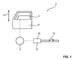
- Fig. 1 schematically an adjusting device 2 with an adjustment part 4 is shown.
- the adjusting device 2 is, for example, an electric window, which is integrated in a door 6 of a motor vehicle.
- the adjusting part 4 is in this case a window pane, which is moved by means of a drive 8 along an adjustment path 10.
- the drive 8 is controlled by means of a control unit 12, which is activated by a button 14 by an occupant of the motor vehicle.
- a speed and force control 16 Within the control unit 12 is a speed and force control 16.
- the drive 8 is for example an electric motor which is operated by means of pulse width modulation. By means of variation of the pulse / pause ratio, the electric power supplied to the drive 8 is controlled. In particular, this energy is functionally related to the driving force 18, which spans the adjusting part 4 along the adjustment path 10. The relationship is linear, for example, and during the control, the applied to the electric motor electrical voltage in particular constant. Furthermore, the electric motor preferably has two Hall sensors, by means of which the speed of the electric motor and thus the speed 20 of the drive 8 is measured.
- Fig. 2 shows the timing of a method for operating the adjusting device 2, in particular during a closing operation of the window pane.
- the method is integrated in the speed and force control 16.
- a speed control 26 comes into force, which regulates the speed 20 of the drive 8 to a speed set value 28.
- the starting event 22 is, for example, the actuation of the pushbutton 14 or the reaching of a specific position along the adjustment path 10 by the adjusting part 4.
- the drive force 18 required for the adjustment before a third time period 30 is stored as a force set point 32. Further, the driving force 18 is monitored by means of a monitoring unit 34, whether a binding 36 is present. If, for example, the drive force 18 rises very sharply or is higher than a certain limit value, the monitoring unit 34 outputs a positive signal 38. Otherwise, the monitoring unit 34 outputs a negative signal 40. The negative signal 40 is monitored in a further monitoring unit 34. whether the adjustment part 4 has reached the end of the adjustment path 10 or at least the end of the region of the adjustment path 10 within which the adjustment part 4 is moved by means of the method. If so, an end event 42 terminates the process. Otherwise, by means of the speed control 26, the speed 20 of the adjusting part 4 is regulated to the speed setpoint 28.
- the drive force 18 is regulated to the desired force value 32 for a first time interval 46 by means of a force control 44. After expiration of the first period of time 46, a check is made by means of a further monitoring unit 34 as to whether the binding 36 is a trapping case 48. The distinction is made on the basis of the realized speed 20 of the drive 8. For example, if the speed 20 is zero or near zero, the pinch case 48 is identified. Should an object, such as a hand of one of the occupants of the motor vehicle, be acted upon by the window, then an entrapment event 50 occurs.
- the drive 8 is either stopped or controlled such that the adjusting part 4 moves in the direction opposite to the original direction of movement, so that the object is released from the entrapment. Otherwise, if there is no entrapment 48, the speed 20 of the drive 8 is linearly adjusted again to the speed setpoint 28 by means of a speed adjustment unit 52. The speed control 26 then becomes active again.
- Fig. 3 is extracts of the time course of the driving force 18 and the speed 20 of the drive 8 shown.
- the speed 20 is regulated to the speed setpoint 28. If the driving force 18 required for this exceeds a limit, the case of stiffness 36 is identified.
- the driving force 18 for the first period 46 is regulated to the force command value 32.
- the value of the driving force 18, which served as the driving force 18 for the third time period 30 before the beginning of the binding 36 is used as the desired force value 32.
- the driving force 18 is first reduced to a first force 54, wherein the first force 54 is almost zero.
- the drive force 18 is increased linearly to the desired force value 32.
- the speed 20 of the drive 8 is monitored. If this value is zero or almost zero after expiration of the first period of time 46, it is assumed that an object is located within the adjustment path 10 and thus the trapping case 48 is present. To end the entrapment of the drive 8 is then reversed. The adjusting part 4 now moves in the direction opposite to the original direction of movement. After a certain period of time has elapsed, for example, the drive 8 is completely stopped.
- Fig. 4 is - unlike the one in Fig. 3
- the speed 20 is no longer zero, for example, as shown here, it is approximately one-third of the speed set point 28.
- the controller again adapts to the speed setpoint 28, wherein the speed 20 is increased linearly to the speed setpoint 28. Occurs within a fourth time period 58 after the first time period 46, a further binding 36, then the previous force setpoint 32 is used in the renewed force control. Only after expiration of the fourth time period 58 is the desired force value 32 again updated and corresponds to the respective required before the third period 30 for the adjustment driving force 18. If there is no further binding 36 before, the adjustment is 2 again in normal operation 24th
Abstract
Zum Steuern einer Verstelleinrichtung (2) eines Kraftfahrzeugs, insbesondere eines Fensterhebers, mit einem motorisch angetriebenen Verstellteil (4) wird zumindest in einem Teilbereich eines Verstellweges (10) im Normalbetrieb (24) die Geschwindigkeit (20) des Antriebs (8) auf einen Geschwindigkeits-Sollwert (28) und im Fall einer Schwergängigkeit (36) für eine erste Zeitspanne (46) die Antriebskraft (18) auf einen Kraft-Sollwert (32) geregelt. Nach Ablauf der ersten Zeitspanne (46) wird das Verstellteil (4) reversiert oder der Antrieb (8) zumindest angehalten, wenn ein Einklemmfall (48) eingetreten ist. Wenn der Fall der Schwergängigkeit (36) kein Einklemmfall (48) ist, wird die Geschwindigkeit (20) des Antriebs (8) erneut auf den Geschwindigkeits-Sollwert (28) geregelt, wobei die Antriebskraft (18) zunächst auf eine erste Kraft (54) vermindert und innerhalb einer zweiten Zeitspanne (56) auf den Kraft-Sollwert (32) erhöht und/oder als Kraft-Sollwert (32) ein während des Normalbetriebs (24) realisierter Wert für die Antriebskraft (18) herangezogen wird.For controlling an adjusting device (2) of a motor vehicle, in particular a window lifter, with a motor-driven adjusting part (4), the speed (20) of the drive (8) is at a speed in at least part of an adjustment path (10) during normal operation (24) Setpoint (28) and in the case of a stiffness (36) for a first time period (46), the drive force (18) to a force setpoint (32) regulated. After expiration of the first time period (46), the adjusting part (4) is reversed or the drive (8) is at least stopped when a trapping case (48) has occurred. If the case of stiffness (36) is not an entrapment (48), the speed (20) of the drive (8) is again controlled to the speed setpoint (28), the drive force (18) being initially applied to a first force (54 ) and increased within a second period (56) to the force setpoint (32) and / or as a force setpoint (32) during normal operation (24) realized value for the drive force (18) is used.
Description
Die Erfindung betrifft ein Verfahren zum Steuern einer Verstelleinrichtung eines Kraftfahrzeugs sowie eine danach arbeitende Verstelleinrichtung.The invention relates to a method for controlling an adjusting device of a motor vehicle and an adjusting device operating thereafter.
In der
Aus der
Aus der
Der Erfindung liegt die Aufgabe zugrunde, ein verbessertes Verfahren zum Steuern einer Verstelleinrichtung eines Kraftfahrzeugs anzugeben, bei dem ein sicheres Verstellen des Verstellteils gewährleistet ist. Dabei sollen insbesondere auch etwaige Einklemmkräfte reduziert werden. Des Weiteren soll eine geeignete Verstelleinrichtung eines Kraftfahrzeugs mit einem motorisch angetriebenen Verstellteil angegeben werden.The invention has for its object to provide an improved method for controlling an adjustment of a motor vehicle, in which a secure adjustment of the adjustment is guaranteed. In particular, any trapping forces are to be reduced. Furthermore, a suitable adjustment of a motor vehicle to be specified with a motor-driven adjustment.
Bezüglich des Verfahrens wird diese Aufgabe erfindungsgemäß gelöst durch die Merkmale der Ansprüche 1 und 2. Vorteilhafte Weiterbildungen und Ausgestaltungen sind Gegenstand der hierauf rückbezogenen Unteransprüche.With regard to the method, this object is achieved by the features of
Die Verstelleinrichtung des Kraftfahrzeugs ist beispielsweise eine elektrisch betätigbare Fahrzeugtür, eine Heckklappe, ein elektrischer Fensterheber, ein elektrisches Schiebedach oder auch eine Verdunklungseinrichtung. Insbesondere findet das vorgeschlagene Verfahren hierbei bevorzugt Anwendung während einer Schließbewegung des Verstellteils. Im Normalbetrieb wird die Geschwindigkeit des Antriebs, mittels dessen das Verstellteil entlang eines Verstellweges verbracht wird, auf einen Geschwindigkeits-Sollwert geregelt, wobei diese Regelung zumindest in einem Teilbereich des Verstellweges erfolgt.The adjustment of the motor vehicle is for example an electrically operated vehicle door, a tailgate, an electric window, an electric sunroof or a darkening device. In particular, the proposed method is preferably used during a closing movement of the adjustment. In normal operation, the speed of the drive is spent by means of which the adjustment part along an adjustment path is controlled to a speed setpoint, this control is carried out at least in a portion of the adjustment.
Der Geschwindigkeits-Sollwert ist beispielsweise zumindest abschnittsweise entlang des Verstellwegs konstant oder steht in funktionalem Zusammenhang mit dem bereits zurückgelegten Verstellweg und/oder der Position des Verstellteils. Insbesondere ist bei der Steuerung eines elektrischen Fensterhebers der Geschwindigkeits-Sollwert bei einem Einfahren der Fensterscheibe in einen üblicherweise mit einem Dichtgummi versehenen oberen Scheibenanschlag im Vergleich zu dem sonstigen Geschwindigkeits-Sollwert reduziert. Der Geschwindigkeits-Sollwert ist beispielsweise in einer Tabelle oder in einem Kennfeld gespeichert, wobei hierbei insbesondere der Geschwindigkeits-Sollwert in Abhängigkeit von der Betriebs- und/oder der Umgebungstemperatur sowie weiteren Umgebungsvariablen hinterlegt ist.The speed setpoint value is, for example, constant at least in sections along the adjustment path or is functionally related to the already traveled adjustment path and / or the position of the adjustment part. In particular, in the control of an electric window lifter, the speed setpoint when the window pane retracts into a top disc stop, which is usually provided with a sealing rubber, is reduced in comparison with the other speed setpoint. The speed setpoint is stored, for example, in a table or in a map, in which case in particular the speed setpoint is stored as a function of the operating and / or the ambient temperature and other environment variables.
Tritt während der Verbringung des Verstellteils im Zuge der Regelung auf den Geschwindigkeits-Sollwert eine Schwergängigkeit auf, so wird die Antriebskraft auf einen Kraft-Sollwert geregelt. Insbesondere ist der Kraft-Sollwert geringer als ein gesetzlich vorgeschriebener Grenzwert oder ein Wert, der zur Beschädigung der Verstelleinrichtung oder etwaiger Insassen des Kraftfahrzeugs führen würde. Beispielsweise ist der Kraft-Sollwert zumindest abschnittsweise entlang des Verstellwegs konstant. Der Kraft-Sollwert kann ebenfalls abhängig von Umgebungsvariablen sein.If stiffness occurs during the movement of the adjustment part in the course of regulation to the speed setpoint, the drive force is regulated to a force setpoint value. In particular, the force setpoint is less than a legal limit or a value that would damage the adjuster or any occupant of the vehicle. For example, the force setpoint is constant at least in sections along the adjustment path. The force set point can also be dependent on environment variables.
Diese Regelung ist für eine erste Zeitspanne aktiv, wobei die Zeitspanne beispielsweise durch einen Benutzer veränderbar ist. Insbesondere ist diese Zeitspanne mittels Betätigen eines Schalters, welcher die Verstelleinrichtung steuert, wie zum Beispiel einem Taster des elektrischen Fensterhebers, verkürz- oder verlängerbar. Geeigneterweise ist die erste Zeitspanne an aktuelle Anforderungen oder Betriebsbedingungen der Verstelleinrichtung angepasst. Insbesondere ist die erste Zeitspanne jedoch konstant und beträgt beispielsweise zwischen 0,1 s und 1 s, vorzugsweise 0,5s.This control is active for a first period of time, wherein the time period is variable, for example, by a user. In particular, this time span can be shortened or extended by actuating a switch which controls the adjusting device, for example a push button of the electric window lifter. Suitably, the first time period is adapted to current requirements or operating conditions of the adjustment device. In particular, however, the first time period is constant and is for example between 0.1 s and 1 s, preferably 0.5 s.
Nach Ablauf der ersten Zeitspanne wird im Einklemmfall der mit dem Verstellteil in Wirkverbindung stehende Antrieb angehalten oder das Verstellteil reversiert. Der Antrieb wird somit derart angesteuert, dass das Verstellteil entlang des Verstellweges in die der ursprünglichen Bewegungsrichtung entgegengesetzte Richtung verbracht wird.After the expiry of the first period of time, in the case of trapping, the drive operatively connected to the adjusting part is stopped or the adjusting part is reversed. The drive is thus controlled in such a way that the adjusting part is moved along the adjustment path in the direction opposite to the original direction of movement.
Unter Einklemmfall wird verstanden, dass die Schwergängigkeit von einem Objekt verursacht ist, das sich innerhalb des Verstellbereiches des Verstellteils und in mechanischem Kontakt zu diesem befindet. Das Objekt, beispielsweise ein Körperteil einer Person, wie eine Hand, soll vor einer Verletzung oder einer Beschädigung geschützt werden. Zusätzlich oder alternativ soll die Verstelleinrichtung vor einer Beschädigung geschützt werden, falls das Objekt derart ausgestaltet ist, dass ein weiteres Verbringen des Verstellteils entlang des Verstellweges in der ursprünglichen Bewegungsrichtung zu einer Beschädigung der Verstelleinrichtung führen würde. Insbesondere wirkt das Objekt der ursprünglichen Bewegungsrichtung des Verstellteils entgegen.Pinching is understood to mean that the binding is caused by an object that is within the adjustment range of the adjustment member and in mechanical contact therewith. The object, for example a body part of a person, such as a hand, is to be protected from injury or damage. Additionally or alternatively, the adjustment should be protected from damage, if the object is designed such that a further movement of the adjustment along the adjustment path in the original direction of movement would lead to damage to the adjustment. In particular, the object counteracts the original direction of movement of the adjustment.
Liegt kein Einklemmfall vor, also ist beispielsweise die Schwergängigkeit auf eine kurzzeitige Störung der Verstelleinrichtung, wie insbesondere eine Erschütterung oder eine Verschmutzung innerhalb etwaiger Führungsschienen zurückzuführen, innerhalb derer sich das Verstellteil befindet, so wird das Verstellteil nach Ablauf der ersten Zeitspanne erneut auf den Geschwindigkeits-Sollwert geregelt.If there is no entrapment, so for example, the binding is due to a short-term disturbance of the adjustment, such as in particular a vibration or contamination within any guide rails, within which the adjustment is located, so the adjustment is again after the first period of time on the speed Setpoint controlled.
Aufgrund der Regelung der Antriebsgeschwindigkeit ist gewährleistet, dass das Verstellteil im Normalbetrieb stets in annähernd der gleichen Zeitspanne entlang des Verstellwegs verbracht wird. Dies führt zu einer ansprechenden Wahrnehmung der Insassen des Kraftfahrzeugs hinsichtlich der Verstellbewegung und zu einem vorhersagbaren Zeitpunkt, zu dem sich das Verstellteil in einer bestimmten Position befindet. Weiterhin führt die beispielsweise durch eine kurze externe Störung hervorgerufen Schwergängigkeit nicht zu einem Abbruch des Verstellens, sondern die Verstelleinrichtung verbringt das Verstellteil sicher entlang des Verstellweges in die gewünschte Position. Sollte die Störung das sich innerhalb des Verstellbereiches befindliche Objekt sein, so wird dieses aufgrund der die Einklemmkraft begrenzenden Kraftregelung nicht verletzt, wobei weiterhin die Verstelleinrichtung selbst nicht beschädigt wird.Due to the regulation of the drive speed ensures that the adjustment is always spent in normal operation in approximately the same time along the Verstellwegs. This leads to an appealing perception of the occupants of the motor vehicle with respect to the adjustment movement and at a predictable point in time when the adjustment part is in a certain position. Furthermore, the stiffness caused, for example, by a brief external disturbance does not lead to a termination of the adjustment, but the adjusting device safely spends the adjustment part along the adjustment path into the desired position. If the disturbance is the object located within the adjustment range, this becomes due to the pinching force limiting force control is not violated, and still the adjustment itself is not damaged.
Die Schwergängigkeit und der Einklemmfall werden beispielsweise mittel zusätzlicher Sensoren, insbesondere mittels Einklemmschutzsensoren in einem Anschlagbereich des Verstellteils, erfasst. In einer bevorzugten Ausführungsform wird jedoch im Normalbetrieb anhand der für die Verstellung des Verstellteils, die mit einer dem Geschwindigkeits-Sollwert entsprechenden Geschwindigkeit erfolgt, benötigten Kraft die Schwergängigkeit erkannt. Beispielsweise wird auf den KraftSollwert geregelt, sobald der Wert für die Antriebskraft einen bestimmten Grenzwert und/oder der Anstieg der benötigten Antriebskraft innerhalb einer definierten Zeitspanne einen bestimmten Anstiegsgrenzwert überschreitet.The stiffness and the Einklemmfall be detected, for example, means of additional sensors, in particular by anti-pinch sensors in a stop region of the adjustment. In a preferred embodiment, however, the binding is detected in normal operation on the basis of the force required for the adjustment of the adjustment, which takes place at a speed corresponding to the speed setpoint required force. For example, the force set point is controlled as soon as the value for the drive force exceeds a certain limit value and / or the increase in the required drive force within a defined period of time exceeds a certain rise limit value.
Sobald auf den Kraft-Sollwert geregelt wird, kann zweckmäßigerweise alternativ oder zusätzlich der Einklemmfall anhand der realisierten Geschwindigkeit des Antriebs erkannt werden. Insbesondere zeichnet sich der Einklemmfall dadurch aus, dass trotz der von dem Antrieb aufgebrachten Antriebskraft in Höhe eines geeigneten Kraft-Sollwerts die Geschwindigkeit des Verstellteils null beträgt. Liegt der Wert der Geschwindigkeit jedoch oberhalb eines bestimmten Grenzwertes oder steigert sich die Geschwindigkeit um einen bestimmten Wert innerhalb eines bestimmten Zeitraums, so wird nach Ablauf der ersten Zeitspanne wieder auf den Geschwindigkeits-Sollwert geregelt. Dabei wird die erste Zeitspanne beispielsweise beendet, sobald der Wert der Geschwindigkeit den bestimmten Grenzwert erreicht.Once it is regulated to the force setpoint, it is expedient to alternatively or additionally detect the trapping case on the basis of the realized speed of the drive. In particular, the trapping case is characterized in that despite the driving force applied by the drive in the amount of a suitable force setpoint, the speed of the adjustment is zero. However, if the value of the speed is above a certain limit value or if the speed increases by a certain value within a certain period of time, the speed setpoint value is regulated again after the first time span has elapsed. In this case, the first time period is terminated, for example, as soon as the value of the speed reaches the specified limit value.
Ist nach Ablauf der ersten Zeitspanne nicht eindeutig feststellbar, ob der Einklemmfall vorliegt, so wird geeigneterweise die erste Zeitspanne solange verlängert, also die Regelung auf den Kraft-Sollwert fortgeführt, bis eine Unterscheidung möglich ist. Dies ist beispielsweise der Fall, wenn das Verstellteil sich zwar entlang des Verstellweges bewegt, der Wert der Geschwindigkeit jedoch unterhalb des bestimmten Grenzwertes liegt.If after the expiry of the first period of time it is not possible to determine unambiguously whether the trapping situation exists, the first period of time is suitably extended, ie the regulation continues to the force setpoint value until a distinction is possible. This is the case, for example, if the adjustment part moves along the adjustment path, but the value of the speed is below the specified limit value.
Geeigneterweise wird nach Ablauf der ersten Zeitspanne, wenn kein Einklemmfall eingetreten ist, die Geschwindigkeit des Verstellteils stetig, insbesondere linear, auf den Geschwindigkeits-Sollwert angepasst. Auf diese Weise werden starke Belastungen der Verstelleinrichtung und/oder hohe auftretende Antriebskräfte vermieden. Weiterhin ist die Geräuschbelastung der Insassen des Kraftfahrzeugs geringer. Ebenso ist das Erscheinungsbild für die Insassen während des Betriebs der Verstelleinrichtung ansprechender, da das Verstellteil keine ruckartigen Bewegungen ausführt.Suitably, after expiration of the first period of time, when no jamming case has occurred, the speed of the adjustment part is adjusted continuously, in particular linearly, to the desired speed value. In this way, heavy loads on the adjustment and / or high occurring driving forces are avoided. Furthermore, the noise level of the occupants of the motor vehicle is lower. Likewise, the appearance of the occupants during operation of the adjustment is more appealing because the adjustment performs no jerky movements.
Zur Reduzierung der etwaigen Einklemmkräfte wird bei Erfassung der Schwergängigkeit, wenn also die Regelung auf den Geschwindigkeits-Sollwert abgebrochen wird, gemäß der ersten Variante der Erfindung die Antriebskraft zunächst auf eine erste Kraft vermindert. Dies hat zur Folge, dass das Objekt nicht mit dem Kraft-Sollwert und einer zusätzlichen Kraft eingeklemmt wird, die dem Trägheitsmoment des Verstellteils entspringt, falls die Schwergängigkeit durch das Objekt hervorgerufen ist. Diese zusätzliche Kraft ist nur äußerst aufwendig bestimmbar, da das Trägheitsmoment von dem Zustand der Verstelleinrichtung abhängt. So beeinflussen insbesondere die Betriebstemperatur und etwaige Verschleißerscheinungen der Verstelleinrichtung das Trägheitsmoment. Innerhalb einer zweiten Zeitspanne wird die Antriebskraft auf den Kraft-Sollwert erhöht. Mit dieser Maßnahme ist sichergestellt, dass das Verstellteil die Schwergängigkeit der Verstelleinrichtung, wie beispielsweise eine Verschmutzung, sicher während der Verstellung überbrückt, wobei die Einklemmkräfte in dem Einklemmfall möglichst gering und beherrschbar bleiben.In order to reduce the possible pinching forces, when the stiffness is detected, ie when the control is canceled to the speed setpoint value, according to the first variant of the invention the driving force is first reduced to a first force. This has the consequence that the object is not clamped with the force setpoint and an additional force, which springs from the moment of inertia of the adjustment, if the stiffness is caused by the object. This additional force can only be determined with great difficulty, since the moment of inertia depends on the state of the adjusting device. In particular, the operating temperature and any signs of wear of the adjusting device influence the moment of inertia. Within a second period of time, the driving force is increased to the force command value. With this measure, it is ensured that the adjusting part safely bridges the stiffness of the adjusting device, such as, for example, contamination during the adjustment, the pinching forces remaining as small and manageable as possible in the trapping case.
Zweckmäßigerweise beträgt die erste Kraft nahezu Null. Hierdurch wird in dem Einklemmfall das Objekt zunächst im Wesentlichen lediglich von der von dem Trägheitsmoment verursachten Kraft beaufschlagt. Diese lässt innerhalb kürzester Zeit nach und führt daher bei einem entsprechenden Geschwindigkeits-Sollwert zu keiner Beschädigung oder Verletzung. Infolgedessen wird das Objekt während der restlichen Regelungsphase auf den Kraft-Sollwert mit einer definierten und bekannten Kraft beaufschlagt. Somit tritt bei einer geeigneten Vorgabe des Kraft-Sollwerts während der Regelung auf diesen ebenfalls keine Beschädigung bzw. Verletzung auf.Conveniently, the first force is nearly zero. As a result, in the trapping case, the object is initially essentially acted upon only by the force caused by the moment of inertia. This decreases within a very short time and therefore leads to no damage or injury at a corresponding speed setpoint. As a result, the object is subjected to the force set point with a defined and known force during the rest of the control phase. Thus occurs with a suitable specification of the force setpoint during the regulation on this also no damage or injury.
Vorteilhafterweise findet die Erhöhung der ersten Kraft auf den Kraft-Sollwert stetig, insbesondere linear, statt. Auf diese Weise werden starke Belastungen der Verstelleinrichtung und des etwaigen Objekts vermieden. Zudem ist die Geräuschbelastung gering. Falls das Objekt eine Hand oder dergleichen eines Insassen ist, werden weiterhin beispielsweise Überreaktionen vermieden, die sich durch eine ruckartige Ansteuerung des Verstellteils ergäben.Advantageously, the increase of the first force to the force setpoint takes place steadily, in particular linearly. In this way, heavy loads on the adjusting device and the possible object are avoided. In addition, the noise level is low. If the object is a hand or the like of an occupant, for example, overreactions are avoided, which would result from a jerky control of the adjustment.
Gemäß der zweiten Variante der Erfindung wird als Kraft-Sollwert ein während des Normalbetriebs realisierter Wert für die Antriebskraft herangezogen, um eine weitere Reduzierung der etwaigen Einklemmkräfte im Einklemmfall zu erreichen. Auch kann in Kombination mit der ersten Variante zur Absenkung der Antriebskraft auf die erste Kraft als Kraft-Sollwert der oder ein während des Normalbetriebs realisierter Wert für die Antriebskraft herangezogen werden. Geeigneterweise wird somit das Objekt während der Phase der Regelung auf den Kraft-Sollwert nicht weiter übermäßig beschädigt oder verletzt, da der Kraft-Sollwert bereits vor Eintreten dieser Regelphase eingetreten ist und während dieser Regelung ebenfalls mit einer Beschädigung oder Verletzung des Objekts gerechnet wurde musste.According to the second variant of the invention, a value for the driving force realized during normal operation is used as the force set value in order to achieve a further reduction of the possible pinching forces in the event of trapping. Also, in combination with the first variant for reducing the driving force to the first force as a force setpoint or a realized during normal operation value for the driving force can be used. Suitably, the object is thus not excessively damaged or injured during the phase of the control to the force setpoint, since the force setpoint has already occurred before the occurrence of this control phase and was also expected during this rule with damage or injury to the object.
Es ist somit beiden Varianten gemeinsam, dass zur Differenzierung zwischen einem Einklemmfall und einer Schwergängigkeit von der Drehzahlregelung auf eine Kraftregelung gewechselt und ein Zeitfenster betrachtet wird. Während bei der ersten Variante der Wechsel auf die Kraftregelung erfolgt, indem die Antriebskraft bzw. die Geschwindigkeit oder Motordrehzahl reduziert und anschließend auf einen vorgegebenen Kraftsollwert geregelt wird, wird bei der zweiten Variante für die Kraftregelung ein vor der Umschaltung von der Geschwindigkeits- bzw. Drehzahlregelung auf die Kraftregelung vorhandener Kraftwert als Sollwert herangezogen, ohne dass zuvor zwingend die Geschwindigkeit bzw. Motordrehzahl reduziert wird.It is thus common to both variants that the differentiation between a trapping case and a stiffness of the speed control is switched to a force control and a time window is considered. While in the first variant, the change takes place on the force control by the driving force or the speed or engine speed is reduced and then controlled to a predetermined force setpoint, in the second variant for the force control before switching from the speed or speed control Force value existing on the force control used as a setpoint, without previously necessarily the speed or engine speed is reduced.
Zweckmäßigerweise wird der Kraft-Sollwert im Normalbetrieb kontinuierlich aktualisiert. In einer vorteilhaften Ausgestaltung entspricht der Kraft-Sollwert dem vor einer dritten Zeitspanne realisierten Wert der Antriebskraft, wobei diese beispielsweise zwischen 0s und 1 s und insbesondere 0,01 s beträgt. Somit ist der Kraft-Sollwert auf aktuelle Anforderungen der Verstelleinrichtungen angepasst, beispielsweise einer veränderten Umgebungstemperatur. Weiterhin werden hierdurch für die Regelung keine weiteren Komponenten innerhalb der Verstelleinrichtung benötigt, wie beispielsweise ein Speicher für das Kennfeld oder weitere Sensoren zur Anpassung des Kraft-Sollwertes an die Umgebungsvariablen.Appropriately, the force setpoint is updated continuously in normal operation. In an advantageous embodiment, the force setpoint corresponds to the value of the drive force realized before a third time span, which is, for example, between 0 s and 1 s and in particular 0.01 s. Thus, the force setpoint is adapted to current requirements of the adjustment, for example, a changed ambient temperature. Furthermore, this means that no further components within the adjusting device are required for the control, such as, for example, a memory for the characteristic map or further sensors for adapting the force setpoint to the environmental variables.
Wird nach Ablauf der ersten Zeitspanne erneut auf den Geschwindigkeits-Sollwert geregelt, so wird geeigneterweise der Kraft-Sollwert für eine vierte Zeitspanne konstant gehalten. Insbesondere wird der Kraft-Sollwert innerhalb der vierten Zeitspanne nicht aktualisiert, wenn die vierte Zeitspanne länger als die dritte Zeitspanne ist. Während dieser vierten Zeitspanne entspricht der Kraft-Sollwert dem Kraft-Sollwert, auf den während der ersten Zeitspanne geregelt wurde. Mit anderen Worten entspricht, nachdem das Verstellteil die Schwergängigkeit überwunden hat und dessen Geschwindigkeit wieder auf den Geschwindigkeits-Sollwert geregelt wird, der Kraft-Sollwert für die Dauer der vierten Zeitspanne dem Kraft-Sollwert, auf den geregelt wurde, während das Verstellteil durch die Schwergängigkeit verbracht wurde.If, after the first time period has elapsed, the speed setpoint is again regulated, the force setpoint is suitably kept constant for a fourth time span. In particular, the force command value is not updated within the fourth time period when the fourth time period is longer than the third time period. During this fourth period of time, the force setpoint corresponds to the force setpoint that was controlled during the first time period. In other words, after the adjusting member has overcome the sluggishness and its speed is again regulated to the speed command value, the force command value for the duration of the fourth time period corresponds to the commanded force value setpoint while the adjusting part is subject to the sluggishness was spent.
Die vierte Zeitspanne beträgt zweckmäßigerweise zwischen 0,05s und 2s und insbesondere 0,5s. Sie ist geeigneterweise konstant oder wird beendet, sobald die Geschwindigkeit des Verstellteils eine Grenzgeschwindigkeit überschreitet. Somit wird beispielsweise verhindert, dass der Kraft-Sollwert im Fall einer Anzahl von Schwergängigkeiten kontinuierlich erhöht wird. So wird häufig während der sich an die erste Zeitspanne anschließenden Geschwindigkeitsregelung eine erhöhte Antriebskraft benötigt, um den Antrieb erneut auf den Geschwindigkeits-Sollwert zu beschleunigen.The fourth time interval is expediently between 0.05 s and 2 s and in particular 0.5 s. It is suitably constant or terminated as soon as the speed of the adjustment exceeds a limit speed. Thus, for example, it is prevented that the force command value is continuously increased in the case of a number of bindings. Thus, often during the first time period subsequent speed control, an increased driving force is required to accelerate the drive again to the speed setpoint.
Bezüglich der Verstelleinrichtung wird die genannte Aufgabe gelöst durch die Merkmale des Anspruchs 9. Hierzu weist die Verstelleinrichtung eine Geschwindigkeits- und Kraftregelung auf, wobei die Regelung beispielsweise in zwei separaten Steuereinheiten oder in einer integrierten Steuereinheit verwirklicht ist. DieWith regard to the adjusting device, the stated object is achieved by the features of claim 9. For this purpose, the adjusting device has a speed and force control, wherein the control is realized for example in two separate control units or in an integrated control unit. The
Regelung ist zumindest dann aktiv, wenn sich das Verstellteil in einem Teilbereich des Verstellweges befindet und das Verstellteil bewegt werden soll. Im Normalbetrieb wird die Geschwindigkeit des Antriebs mittels der Geschwindigkeitsregelung auf einen Geschwindigkeits-Sollwert geregelt.Control is at least active when the adjustment is in a partial region of the adjustment and the adjustment is to be moved. In normal operation, the speed of the drive is controlled by the speed control to a speed setpoint.
Im Fall einer Schwergängigkeit während des Betriebs greift die Kraftregelung ein und regelt für eine erste Zeitspanne die Antriebskraft auf einen Kraft-Sollwert. Nach Ablauf der ersten Zeitspanne wird mittels einer geeigneten Ansteuerung des Antriebs das Verstellteil reversiert oder der Antrieb zumindest angehalten, wenn die Schwergängigkeit auf einen Einklemmfall zurückzuführen ist. Anderenfalls erfolgt nach Ablauf der ersten Zeitspanne eine erneute Regelung der Geschwindigkeit des Antriebs auf den Geschwindigkeits-Sollwert.In the case of sluggishness during operation, the force control intervenes and regulates the drive force to a force setpoint for a first period of time. After expiry of the first period of time, the adjusting part is reversed by means of a suitable control of the drive or the drive is at least stopped when the sluggishness is due to a trapping case. Otherwise, after the expiry of the first time period, the speed of the drive is re-regulated to the speed setpoint.
Beispielsweise sind der Antrieb ein herkömmlicher Elektromotor und die Verstelleinrichtung ein elektrischer Fensterheber. Vorteilhafterweise wird Drehzahl des Elektromotors mittels Hall-Sensoren erfasst und damit die Geschwindigkeit des Antriebs bzw. des Verstellteils gemessen. Geeigneterweise wird der Elektromotor mittels einer an sich bekannten Pulsweitenmodulation mit Energie versorgt. Somit ist über Variation des Pulslänge bzw. des Puls-Pausen-Verhältnisses eine Einstellung der Leistungsabgabe des Elektromotors und somit ein Kontrollieren der Antriebskraft ermöglicht.For example, the drive is a conventional electric motor and the adjustment means an electric window. Advantageously, the rotational speed of the electric motor is detected by means of Hall sensors and thus the speed of the drive or of the adjusting part is measured. Suitably, the electric motor is powered by means of a known pulse width modulation with energy. Thus, an adjustment of the power output of the electric motor and thus controlling the driving force is made possible by varying the pulse length or the pulse-pause ratio.
Ebenfalls ist es möglich, die Stromaufnahme und/oder die an den Elektromotor angelegt elektrische Spannung und somit die Antriebskraft mittels eines variablen Widerstandes zu verändern. Zweckmäßigerweise wird mittels einer motorspezifischen Kennlinie und der gemessenen Drehzahl die Antriebskraft bestimmt. Vorteilhafterweise ist die Geschwindigkeits- und Kraftregelung derart ausgestaltet, dass diese in bereits bestehende Komponenten eines herkömmlichen elektrischen Fensterhebers integrierbar ist, so dass der Fensterheber beispielsweise mittels eines Softwareupdates auf das vorgeschlagene Verfahren umrüstbar ist.It is also possible to change the current consumption and / or the electric voltage applied to the electric motor and thus the driving force by means of a variable resistor. Appropriately, the driving force is determined by means of a motor-specific characteristic and the measured speed. Advantageously, the speed and force control is designed such that it can be integrated into existing components of a conventional power window, so that the window can be converted to the proposed method, for example by means of a software update.
Die Ausgestaltungen des obigen Verfahrens sind sinngemäß auch auf die Verstelleinrichtung übertragbar.The embodiments of the above method are mutatis mutandis transferable to the adjustment.
Nachfolgend wird ein Ausführungsbeispiel der Erfindung anhand einer Zeichnung näher erläutert. Darin zeigen:
- Fig. 1
- in schematischer Darstellung eine Verstelleinrichtung mit einem motorisch angetriebenen Verstellteil,
- Fig. 2
- als Flussdiagramm ein Verfahren zum Betreiben der Verstelleinrichtung mit dem Verstellteil,
- Fig. 3
- einen zeitlichen Verlauf der Geschwindigkeit und der Kraft des Antriebs im Fall einer Schwergängigkeit, die ein Einklemmfall ist, und
- Fig. 4
- die Verläufe gemäß
Fig. 3 in dem Fall, dass die Schwergängigkeit kein Einklemmfall ist.
- Fig. 1
- a schematic representation of an adjustment with a motor-driven adjustment part,
- Fig. 2
- a flowchart as a method for operating the adjusting device with the adjusting part,
- Fig. 3
- a time course of the speed and the power of the drive in the case of a binding, which is a pinching case, and
- Fig. 4
- the courses according to
Fig. 3 in the case that the binding is not a pinching case.
Einander entsprechende Teile sind in allen Figuren mit den gleichen Bezugszeichen versehen.Corresponding parts are provided in all figures with the same reference numerals.
In
Der Antrieb 8 ist beispielsweise ein Elektromotor, der mittels Pulsweitenmodulation betrieben wird. Mittels Variation des Puls-/Pausenverhältnisses wird die dem Antrieb 8 zugeführte elektrische Energie gesteuert. Insbesondere steht diese Energie in funktionalem Zusammenhang mit der Antriebskraft 18, die das Verstellteil 4 entlang des Verstellweges 10 verbringt. Der Zusammenhang ist beispielsweise linear, und während der Steuerung ist die an den Elektromotor angelegte elektrische Spannung insbesondere konstant. Weiterhin weist der Elektromotor vorzugsweise zwei Hall-Sensoren auf, mittels derer die Drehzahl des Elektromotors und somit die Geschwindigkeit 20 des Antriebs 8 gemessen wird.The
Während der Regelung auf den Geschwindigkeits-Sollwert 28, der beispielsweise konstant ist, wird die vor einer dritten Zeitspanne 30 für die Verstellung benötigte Antriebskraft 18 als ein Kraft-Sollwert 32 gespeichert. Ferner wird die Antriebskraft 18 mittels einer Überwachungseinheit 34 überwacht, ob eine Schwergängigkeit 36 vorliegt. Steigt die Antriebskraft 18 beispielsweise sehr stark an oder liegt diese höher als ein bestimmter Grenzwert, so gibt die Überwachungseinheit 34 ein positives Signal 38. Anderenfalls gibt die Überwachungseinheit 34 ein negatives Signal 40. Bei dem negativen Signal 40 wird in einer weiteren Überwachungseinheit 34 überwacht, ob das Verstellteil 4 das Ende des Verstellweges 10 oder zumindest das Ende des Bereiches des Verstellweges 10 erreicht hat, innerhalb dessen das Verstellteil 4 mittels des Verfahrens verbracht wird. Falls dies der Fall ist, tritt ein Endereignis 42 ein, das das Verfahren beendet. Anderenfalls wird weiterhin mittels der Geschwindigkeitsregelung 26 die Geschwindigkeit 20 des Verstellteils 4 auf den Geschwindigkeits-Sollwert 28 geregelt.During control of the
Bei Auftreten der Schwergängigkeit 36 wird mittels einer Kraftregelung 44 die Antriebskraft 18 für eine erste Zeitspanne 46 auf den Kraft-Sollwert 32 geregelt. Nach Ablauf der ersten Zeitspanne 46 wird mittels einer weiteren Überwachungseinheit 34 überprüft, ob die Schwergängigkeit 36 ein Einklemmfall 48 ist. Die Unterscheidung wird anhand der realisierten Geschwindigkeit 20 des Antriebs 8 getroffen. Falls die Geschwindigkeit 20 beispielsweise null oder nahezu null beträgt, ist der Einklemmfall 48 identifiziert. Sollte ein Objekt, wie zum Beispiel eine Hand eines der Insassen des Kraftfahrzeugs, von der Fensterscheibe beaufschlagt werden, so tritt ein Einklemmereignis 50 ein. Hierbei wird der Antrieb 8 entweder angehalten oder derart angesteuert, dass sich das Verstellteil 4 in zur ursprünglichen Bewegungsrichtung entgegengesetzte Richtung bewegt, so dass das Objekt aus der Einklemmung befreit wird. Anderenfalls, wenn kein Einklemmfall 48 vorliegt, wird die Geschwindigkeit 20 des Antriebs 8 mittels einer Geschwindigkeitsanpassungseinheit 52 linear erneut auf den Geschwindigkeits-Sollwert 28 angepasst. Hierauf wird wiederum die Geschwindigkeitsregelung 26 aktiv.When the
In
Innerhalb einer zweiten Zeitspanne 56 wird die Antriebskraft 18 linear auf den Kraft-Sollwert 32 erhöht. Während der ersten Zeitspanne 46 wird die Geschwindigkeit 20 des Antriebs 8 überwacht. Beträgt diese nach Ablauf der ersten Zeitspanne 46 Null oder nahezu Null, so wird davon ausgegangen, dass sich ein Objekt innerhalb des Verstellweges 10 befindet und somit der Einklemmfall 48 vorliegt. Zur Beendigung der Einklemmung wird daraufhin der Antrieb 8 reversiert. Das Verstellteil 4 bewegt sich nun in der zur ursprünglichen Bewegungsrichtung entgegengesetzten Richtung. Nachdem eine gewisse Zeitspanne verstrichen ist, wird beispielsweise der Antrieb 8 vollständig angehalten.Within a
In
- 22
- Verstelleinrichtungadjustment
- 44
- Verstellteiladjusting part
- 66
- Türdoor
- 88th
- Antriebdrive
- 1010
- Verstellwegadjustment
- 1212
- Steuereinheitcontrol unit
- 1414
- Tasterbutton
- 1616
- Geschwindigkeits- und KraftregelungSpeed and force control
- 1818
- Antriebskraftdriving force
- 2020
- Geschwindigkeitspeed
- 2222
- Startereignisstart event
- 2424
- Normalbetriebnormal operation
- 2626
- Geschwindigkeitsregelungcruise control
- 2828
- Geschwindigkeits-SollwertSpeed setpoint
- 3030
- dritte Zeitspannethird time span
- 3232
- Kraft-SollwertForce command
- 3434
- Überwachungseinheitmonitoring unit
- 3636
- Schwergängigkeitbinding
- 3838
- positives Signalpositive signal
- 4040
- negatives Signalnegative signal
- 4242
- EndereignisEnd Event
- 4444
- Kraftregelungforce control
- 4646
- erste Zeitspannefirst time span
- 4848
- Einklemmfallof trapping
- 5050
- Einklemmereignisinvolving pinching
- 5252
- GeschwindigkeitsanpassungseinheitSpeed adjustment unit
- 5454
- erste Kraftfirst strength
- 5656
- zweite Zeitspannesecond time span
- 5858
- vierte Zeitspannefourth time span
Claims (10)
dadurch gekennzeichnet,
characterized,
dadurch gekennzeichnet,
dass nach Ablauf der ersten Zeitspanne (46) die Anpassung der Geschwindigkeit (20) auf den Geschwindigkeits-Sollwert (28) linear erfolgt.Method according to one of claims 1 to 3,
characterized,
that after the expiry of the first period of time (46) the adaptation of the speed (20) to the speed set value (28) takes place linearly.
dadurch gekennzeichnet,
dass im Fall der Schwergängigkeit (36) die Antriebskraft (18) zunächst derart vermindert wird, dass die erste Kraft (54) nahezu Null beträgt.Method according to claim 1,
characterized,
that in the case of the binding (36) the driving force (18) is first reduced such that the first force (54) is nearly zero.
dadurch gekennzeichnet,
dass im Fall der Schwergängigkeit (36) innerhalb der zweiten Zeitspanne (56) die Erhöhung der Antriebskraft (18) auf den Kraft-Sollwert (32) linear erfolgt.Method according to claim 1,
characterized,
that in the case of the binding (36) within the second time span (56) to increase the driving force (18) on the force command value (32) is linear.
dadurch gekennzeichnet,
dass der Kraft-Sollwert (32) im Normalbetrieb (24) kontinuierlich aktualisiert wird und dem vor einer dritten Zeitspanne (30) realisierten Wert der Antriebskraft (18) entspricht.Method according to claim 2,
characterized,
that the force setpoint (32) is continuously updated during normal operation (24) and corresponds to the front of a third time interval (30) realized value of the driving force (18).
dadurch gekennzeichnet,
dass nach Ablauf der ersten Zeitspanne (46) bei der erneuten Regelung auf den Geschwindigkeits-Sollwert (28) innerhalb einer vierten Zeitspanne (58) der Kraft-Sollwert (32) konstant gehalten wird und dem für die vorherige Kraftregelung verwendeten Kraft-Sollwert (32) entspricht.Method according to claim 2,
characterized,
that after expiration of the first period of time (46) during the renewed regulation to the speed set value (28) the force setpoint value (32) is kept constant within a fourth time period (58) and the force setpoint value (32 ) corresponds.
dadurch gekennzeichnet,
dass der Kraft-Sollwert (32) ein während des Normalbetriebs (24) realisierter Wert für die Antriebskraft (18) ist.Adjusting device (2) according to claim 9,
characterized,
that the force setpoint (32) is a during normal operation (24) realized value for the driving force (18).
Applications Claiming Priority (3)
| Application Number | Priority Date | Filing Date | Title |
|---|---|---|---|
| DE102010055650A DE102010055650A1 (en) | 2010-12-22 | 2010-12-22 | Method and device for controlling an adjusting device of a motor vehicle |
| EP11796617.6A EP2656466B1 (en) | 2010-12-22 | 2011-11-21 | Method and device for controlling an adjusting device of a motor vehicle |
| PCT/EP2011/005846 WO2012084109A1 (en) | 2010-12-22 | 2011-11-21 | Method and device for controlling an adjusting device of a motor vehicle |
Related Parent Applications (2)
| Application Number | Title | Priority Date | Filing Date |
|---|---|---|---|
| EP11796617.6A Division-Into EP2656466B1 (en) | 2010-12-22 | 2011-11-21 | Method and device for controlling an adjusting device of a motor vehicle |
| EP11796617.6A Division EP2656466B1 (en) | 2010-12-22 | 2011-11-21 | Method and device for controlling an adjusting device of a motor vehicle |
Publications (2)
| Publication Number | Publication Date |
|---|---|
| EP2993751A1 true EP2993751A1 (en) | 2016-03-09 |
| EP2993751B1 EP2993751B1 (en) | 2019-06-12 |
Family
ID=45349143
Family Applications (2)
| Application Number | Title | Priority Date | Filing Date |
|---|---|---|---|
| EP15180934.0A Not-in-force EP2993751B1 (en) | 2010-12-22 | 2011-11-21 | Method and device for controlling an adjusting device of a motor vehicle |
| EP11796617.6A Not-in-force EP2656466B1 (en) | 2010-12-22 | 2011-11-21 | Method and device for controlling an adjusting device of a motor vehicle |
Family Applications After (1)
| Application Number | Title | Priority Date | Filing Date |
|---|---|---|---|
| EP11796617.6A Not-in-force EP2656466B1 (en) | 2010-12-22 | 2011-11-21 | Method and device for controlling an adjusting device of a motor vehicle |
Country Status (5)
| Country | Link |
|---|---|
| US (1) | US9388762B2 (en) |
| EP (2) | EP2993751B1 (en) |
| CN (1) | CN103270661B (en) |
| DE (1) | DE102010055650A1 (en) |
| WO (1) | WO2012084109A1 (en) |
Cited By (1)
| Publication number | Priority date | Publication date | Assignee | Title |
|---|---|---|---|---|
| DE102018205342A1 (en) * | 2018-04-10 | 2019-10-10 | Brose Fahrzeugteile Gmbh & Co. Kommanditgesellschaft, Bamberg | Method for operating a pinch protection |
Families Citing this family (8)
| Publication number | Priority date | Publication date | Assignee | Title |
|---|---|---|---|---|
| DE102010055650A1 (en) * | 2010-12-22 | 2012-06-28 | Brose Fahrzeugteile Gmbh & Co. Kommanditgesellschaft, Hallstadt | Method and device for controlling an adjusting device of a motor vehicle |
| US10464399B2 (en) * | 2015-01-30 | 2019-11-05 | Denso Corporation | Vehicle window opening device |
| US10208520B2 (en) | 2016-05-16 | 2019-02-19 | Schlage Lock Company Llc | Method and apparatus for adjusting the closing force of a door |
| DE102016208596A1 (en) * | 2016-05-19 | 2017-11-23 | Robert Bosch Gmbh | Method for operating a locking device and a locking device |
| US10030432B1 (en) | 2017-06-20 | 2018-07-24 | Ford Global Technologies, Llc | System and method for window motion control |
| DE102017215383A1 (en) * | 2017-09-01 | 2019-03-07 | Brose Fahrzeugteile Gmbh & Co. Kommanditgesellschaft, Bamberg | Method for operating a door module of a motor vehicle |
| CN108909419A (en) * | 2018-07-16 | 2018-11-30 | 英纳法企业管理(上海)有限公司 | Vehicle dormer window anti-clamping method and system |
| DE102019114540A1 (en) * | 2019-05-29 | 2020-12-03 | Brose Schließsysteme GmbH & Co. Kommanditgesellschaft | Functional component of a motor vehicle lock arrangement |
Citations (3)
| Publication number | Priority date | Publication date | Assignee | Title |
|---|---|---|---|---|
| DE19615581A1 (en) | 1996-04-19 | 1997-10-23 | Bayerische Motoren Werke Ag | Control of electric drives in vehicles e.g. for wind-screen washer drive |
| DE19901840A1 (en) | 1999-01-19 | 2000-05-25 | Daimler Chrysler Ag | Electrical actuator for motor vehicle electric window, sliding roof or seat adjuster measures instantaneous rotation speed and/or torque and adjusts motor current accordingly |
| EP0966782B1 (en) | 1997-03-12 | 2001-10-24 | Brose Fahrzeugteile GmbH & Co. KG, Coburg | Method for electronic control and adjustment of the movement of electrically actuated units |
Family Cites Families (13)
| Publication number | Priority date | Publication date | Assignee | Title |
|---|---|---|---|---|
| US6064165A (en) * | 1992-04-22 | 2000-05-16 | Nartron Corporation | Power window or panel controller |
| US5982124A (en) * | 1995-08-30 | 1999-11-09 | Trw Inc. | Method and apparatus for adaptive control of a vehicle power window |
| ES2155413B1 (en) * | 1999-10-22 | 2002-02-01 | Castellon Melchor Daumal | IMPROVEMENTS IN THE ANTIPINZING SYSTEMS INTENDED FOR THE CAR. |
| DE202006002525U1 (en) * | 2006-02-17 | 2007-07-05 | Brose Fahrzeugteile Gmbh & Co. Kommanditgesellschaft, Coburg | Anti-jamming protection of a motor-driven adjusting device for an adjusting device |
| US7479748B2 (en) * | 2006-10-25 | 2009-01-20 | Robert Bosch Gmbh | Systems and methods of tracking partition system performance |
| DE102008032963A1 (en) | 2008-07-09 | 2010-01-14 | Brose Fahrzeugteile Gmbh & Co. Kommanditgesellschaft, Coburg | Contour-controlled window regulator for vehicle, has actuator, which is connected with window pane of vehicle and is driven by drive mechanism for adjusting window pane |
| CN201306085Y (en) * | 2008-09-26 | 2009-09-09 | 瑞安市登峰福利汽配厂 | Controller for automobile windows |
| DE102008053113A1 (en) | 2008-10-25 | 2010-05-06 | Brose Fahrzeugteile Gmbh & Co. Kg, Hallstadt | Drive arrangement for the motorized adjustment of an adjusting element in a motor vehicle |
| DE102008043483A1 (en) * | 2008-11-05 | 2010-05-06 | Robert Bosch Gmbh | Method and device for activating monitoring by a anti-trap function in an electrical locking system |
| DE202009000907U1 (en) | 2009-01-23 | 2010-06-17 | Brose Fahrzeugteile Gmbh & Co. Kommanditgesellschaft, Hallstadt | Drive arrangement for the motorized adjustment of an adjusting element of a motor vehicle |
| DE102009027597A1 (en) * | 2009-07-09 | 2011-01-13 | Robert Bosch Gmbh | Method for operating a locking device of a motor vehicle and a locking device |
| DE102010055650A1 (en) * | 2010-12-22 | 2012-06-28 | Brose Fahrzeugteile Gmbh & Co. Kommanditgesellschaft, Hallstadt | Method and device for controlling an adjusting device of a motor vehicle |
| DE102011111450A1 (en) * | 2011-08-30 | 2013-02-28 | Brose Fahrzeugteile Gmbh & Co. Kommanditgesellschaft, Hallstadt | Method and device for monitoring a drive unit having a rotating drive motor, in particular a window lifter |
-
2010
- 2010-12-22 DE DE102010055650A patent/DE102010055650A1/en not_active Withdrawn
-
2011
- 2011-11-21 WO PCT/EP2011/005846 patent/WO2012084109A1/en active Application Filing
- 2011-11-21 EP EP15180934.0A patent/EP2993751B1/en not_active Not-in-force
- 2011-11-21 EP EP11796617.6A patent/EP2656466B1/en not_active Not-in-force
- 2011-11-21 CN CN201180061934.0A patent/CN103270661B/en not_active Expired - Fee Related
-
2013
- 2013-06-24 US US13/924,747 patent/US9388762B2/en active Active
Patent Citations (3)
| Publication number | Priority date | Publication date | Assignee | Title |
|---|---|---|---|---|
| DE19615581A1 (en) | 1996-04-19 | 1997-10-23 | Bayerische Motoren Werke Ag | Control of electric drives in vehicles e.g. for wind-screen washer drive |
| EP0966782B1 (en) | 1997-03-12 | 2001-10-24 | Brose Fahrzeugteile GmbH & Co. KG, Coburg | Method for electronic control and adjustment of the movement of electrically actuated units |
| DE19901840A1 (en) | 1999-01-19 | 2000-05-25 | Daimler Chrysler Ag | Electrical actuator for motor vehicle electric window, sliding roof or seat adjuster measures instantaneous rotation speed and/or torque and adjusts motor current accordingly |
Cited By (1)
| Publication number | Priority date | Publication date | Assignee | Title |
|---|---|---|---|---|
| DE102018205342A1 (en) * | 2018-04-10 | 2019-10-10 | Brose Fahrzeugteile Gmbh & Co. Kommanditgesellschaft, Bamberg | Method for operating a pinch protection |
Also Published As
| Publication number | Publication date |
|---|---|
| EP2656466B1 (en) | 2016-02-03 |
| WO2012084109A1 (en) | 2012-06-28 |
| DE102010055650A1 (en) | 2012-06-28 |
| CN103270661B (en) | 2015-08-19 |
| US20130276748A1 (en) | 2013-10-24 |
| EP2993751B1 (en) | 2019-06-12 |
| US9388762B2 (en) | 2016-07-12 |
| EP2656466A1 (en) | 2013-10-30 |
| CN103270661A (en) | 2013-08-28 |
Similar Documents
| Publication | Publication Date | Title |
|---|---|---|
| EP2656466B1 (en) | Method and device for controlling an adjusting device of a motor vehicle | |
| EP0865137B2 (en) | Method of controlling the closing procedure of closable devices with at least one part driven by an electric motor | |
| EP0910883B1 (en) | Method for controlling the closing process of closing devices with at least one part moved by an electromotor | |
| DE19632910C2 (en) | Method for non-contact approaching the lower stop position of a power window of a motor vehicle | |
| EP1332538B1 (en) | Method for controlling an adjustment process for a piece | |
| DE102009014808A1 (en) | Method and device for driving a control element having a response delay of a drive device | |
| EP0966782A1 (en) | Method for electronic control and adjustment of the movement of electrically actuated units | |
| EP0654882A1 (en) | Process for monitoring movable elements | |
| EP2760129B1 (en) | Positioning device for a moveable motor vehicle part | |
| EP2999838A1 (en) | Anti-trap protection system for a window in a vehicle door, comprising a closing aid | |
| DE202008004451U1 (en) | adjustment | |
| DE19700828C5 (en) | Method for operating an automatic door system | |
| DE102011110081A1 (en) | Method for controlling electromotive adjusting drive of e.g. windshield of motor vehicle, involves controlling rotational speed of motor in response to manual or automatic operating stage triggered by operating element | |
| EP1438778B1 (en) | Method for monitoring the reversing process of electrically actuatable units | |
| WO2001061835A2 (en) | Method for controlling an electric driving motor of an adjusting device pertaining to a motor vehicle | |
| EP0927447B1 (en) | Actuator, in particular an electric motor gear drive system, for moving closure parts operated by extraneous force | |
| DE102017218428B3 (en) | Method for operating a closing device of a motor vehicle and closing device of a motor vehicle | |
| DE102005044147A1 (en) | Electromechanical adjusting device movement controlling method for motor vehicle, involves calculating adjusting movement, which is carried out before or during previous stopping of vehicle, and storing movement in non-volatile memory | |
| EP2193585B1 (en) | Adjustment device | |
| WO2019211086A1 (en) | Control device and method for controlling a window lifter with anti-trap protection for a motor vehicle | |
| DE102012107359B4 (en) | Method for securing a traction device to at least one guide and window regulator system with means for securing | |
| DE10325888B4 (en) | Method for operating an actuating device for a third-party actuator | |
| WO2005071812A1 (en) | Method for evaluating information on the rotational speed and rotational position of a dc-motor | |
| DE102021210346A1 (en) | Method for operating an electromotive adjusting drive of a motor vehicle | |
| DE102016209986A1 (en) | Method for operating an electromotive adjusting drive |
Legal Events
| Date | Code | Title | Description |
|---|---|---|---|
| PUAI | Public reference made under article 153(3) epc to a published international application that has entered the european phase |
Free format text: ORIGINAL CODE: 0009012 |
|
| AC | Divisional application: reference to earlier application |
Ref document number: 2656466 Country of ref document: EP Kind code of ref document: P |
|
| AK | Designated contracting states |
Kind code of ref document: A1 Designated state(s): AL AT BE BG CH CY CZ DE DK EE ES FI FR GB GR HR HU IE IS IT LI LT LU LV MC MK MT NL NO PL PT RO RS SE SI SK SM TR |
|
| RAP1 | Party data changed (applicant data changed or rights of an application transferred) |
Owner name: BROSE FAHRZEUGTEILE GMBH & CO. KOMMANDITGESELLSCHA |
|
| 17P | Request for examination filed |
Effective date: 20160909 |
|
| RBV | Designated contracting states (corrected) |
Designated state(s): AL AT BE BG CH CY CZ DE DK EE ES FI FR GB GR HR HU IE IS IT LI LT LU LV MC MK MT NL NO PL PT RO RS SE SI SK SM TR |
|
| GRAP | Despatch of communication of intention to grant a patent |
Free format text: ORIGINAL CODE: EPIDOSNIGR1 |
|
| STAA | Information on the status of an ep patent application or granted ep patent |
Free format text: STATUS: GRANT OF PATENT IS INTENDED |
|
| INTG | Intention to grant announced |
Effective date: 20190123 |
|
| GRAS | Grant fee paid |
Free format text: ORIGINAL CODE: EPIDOSNIGR3 |
|
| GRAA | (expected) grant |
Free format text: ORIGINAL CODE: 0009210 |
|
| STAA | Information on the status of an ep patent application or granted ep patent |
Free format text: STATUS: THE PATENT HAS BEEN GRANTED |
|
| AC | Divisional application: reference to earlier application |
Ref document number: 2656466 Country of ref document: EP Kind code of ref document: P |
|
| AK | Designated contracting states |
Kind code of ref document: B1 Designated state(s): AL AT BE BG CH CY CZ DE DK EE ES FI FR GB GR HR HU IE IS IT LI LT LU LV MC MK MT NL NO PL PT RO RS SE SI SK SM TR |
|
| REG | Reference to a national code |
Ref country code: GB Ref legal event code: FG4D Free format text: NOT ENGLISH |
|
| REG | Reference to a national code |
Ref country code: CH Ref legal event code: EP |
|
| REG | Reference to a national code |
Ref country code: AT Ref legal event code: REF Ref document number: 1143843 Country of ref document: AT Kind code of ref document: T Effective date: 20190615 |
|
| REG | Reference to a national code |
Ref country code: DE Ref legal event code: R096 Ref document number: 502011015799 Country of ref document: DE |
|
| REG | Reference to a national code |
Ref country code: IE Ref legal event code: FG4D Free format text: LANGUAGE OF EP DOCUMENT: GERMAN |
|
| REG | Reference to a national code |
Ref country code: SE Ref legal event code: TRGR |
|
| REG | Reference to a national code |
Ref country code: NL Ref legal event code: MP Effective date: 20190612 |
|
| REG | Reference to a national code |
Ref country code: LT Ref legal event code: MG4D |
|
| PG25 | Lapsed in a contracting state [announced via postgrant information from national office to epo] |
Ref country code: NO Free format text: LAPSE BECAUSE OF FAILURE TO SUBMIT A TRANSLATION OF THE DESCRIPTION OR TO PAY THE FEE WITHIN THE PRESCRIBED TIME-LIMIT Effective date: 20190912 Ref country code: LT Free format text: LAPSE BECAUSE OF FAILURE TO SUBMIT A TRANSLATION OF THE DESCRIPTION OR TO PAY THE FEE WITHIN THE PRESCRIBED TIME-LIMIT Effective date: 20190612 Ref country code: FI Free format text: LAPSE BECAUSE OF FAILURE TO SUBMIT A TRANSLATION OF THE DESCRIPTION OR TO PAY THE FEE WITHIN THE PRESCRIBED TIME-LIMIT Effective date: 20190612 Ref country code: HR Free format text: LAPSE BECAUSE OF FAILURE TO SUBMIT A TRANSLATION OF THE DESCRIPTION OR TO PAY THE FEE WITHIN THE PRESCRIBED TIME-LIMIT Effective date: 20190612 Ref country code: AL Free format text: LAPSE BECAUSE OF FAILURE TO SUBMIT A TRANSLATION OF THE DESCRIPTION OR TO PAY THE FEE WITHIN THE PRESCRIBED TIME-LIMIT Effective date: 20190612 |
|
| PG25 | Lapsed in a contracting state [announced via postgrant information from national office to epo] |
Ref country code: BG Free format text: LAPSE BECAUSE OF FAILURE TO SUBMIT A TRANSLATION OF THE DESCRIPTION OR TO PAY THE FEE WITHIN THE PRESCRIBED TIME-LIMIT Effective date: 20190912 Ref country code: RS Free format text: LAPSE BECAUSE OF FAILURE TO SUBMIT A TRANSLATION OF THE DESCRIPTION OR TO PAY THE FEE WITHIN THE PRESCRIBED TIME-LIMIT Effective date: 20190612 Ref country code: LV Free format text: LAPSE BECAUSE OF FAILURE TO SUBMIT A TRANSLATION OF THE DESCRIPTION OR TO PAY THE FEE WITHIN THE PRESCRIBED TIME-LIMIT Effective date: 20190612 Ref country code: GR Free format text: LAPSE BECAUSE OF FAILURE TO SUBMIT A TRANSLATION OF THE DESCRIPTION OR TO PAY THE FEE WITHIN THE PRESCRIBED TIME-LIMIT Effective date: 20190913 |
|
| PG25 | Lapsed in a contracting state [announced via postgrant information from national office to epo] |
Ref country code: SK Free format text: LAPSE BECAUSE OF FAILURE TO SUBMIT A TRANSLATION OF THE DESCRIPTION OR TO PAY THE FEE WITHIN THE PRESCRIBED TIME-LIMIT Effective date: 20190612 Ref country code: PT Free format text: LAPSE BECAUSE OF FAILURE TO SUBMIT A TRANSLATION OF THE DESCRIPTION OR TO PAY THE FEE WITHIN THE PRESCRIBED TIME-LIMIT Effective date: 20191014 Ref country code: EE Free format text: LAPSE BECAUSE OF FAILURE TO SUBMIT A TRANSLATION OF THE DESCRIPTION OR TO PAY THE FEE WITHIN THE PRESCRIBED TIME-LIMIT Effective date: 20190612 Ref country code: NL Free format text: LAPSE BECAUSE OF FAILURE TO SUBMIT A TRANSLATION OF THE DESCRIPTION OR TO PAY THE FEE WITHIN THE PRESCRIBED TIME-LIMIT Effective date: 20190612 Ref country code: RO Free format text: LAPSE BECAUSE OF FAILURE TO SUBMIT A TRANSLATION OF THE DESCRIPTION OR TO PAY THE FEE WITHIN THE PRESCRIBED TIME-LIMIT Effective date: 20190612 |
|
| PGFP | Annual fee paid to national office [announced via postgrant information from national office to epo] |
Ref country code: SE Payment date: 20191111 Year of fee payment: 9 Ref country code: CZ Payment date: 20191113 Year of fee payment: 9 |
|
| PG25 | Lapsed in a contracting state [announced via postgrant information from national office to epo] |
Ref country code: ES Free format text: LAPSE BECAUSE OF FAILURE TO SUBMIT A TRANSLATION OF THE DESCRIPTION OR TO PAY THE FEE WITHIN THE PRESCRIBED TIME-LIMIT Effective date: 20190612 Ref country code: IS Free format text: LAPSE BECAUSE OF FAILURE TO SUBMIT A TRANSLATION OF THE DESCRIPTION OR TO PAY THE FEE WITHIN THE PRESCRIBED TIME-LIMIT Effective date: 20191012 Ref country code: SM Free format text: LAPSE BECAUSE OF FAILURE TO SUBMIT A TRANSLATION OF THE DESCRIPTION OR TO PAY THE FEE WITHIN THE PRESCRIBED TIME-LIMIT Effective date: 20190612 Ref country code: IT Free format text: LAPSE BECAUSE OF FAILURE TO SUBMIT A TRANSLATION OF THE DESCRIPTION OR TO PAY THE FEE WITHIN THE PRESCRIBED TIME-LIMIT Effective date: 20190612 |
|
| PGFP | Annual fee paid to national office [announced via postgrant information from national office to epo] |
Ref country code: FR Payment date: 20191014 Year of fee payment: 9 |
|
| REG | Reference to a national code |
Ref country code: DE Ref legal event code: R097 Ref document number: 502011015799 Country of ref document: DE |
|
| REG | Reference to a national code |
Ref country code: DE Ref legal event code: R081 Ref document number: 502011015799 Country of ref document: DE Owner name: BROSE FAHRZEUGTEILE SE & CO. KOMMANDITGESELLSC, DE Free format text: FORMER OWNER: BROSE FAHRZEUGTEILE GMBH & CO. KOMMANDITGESELLSCHAFT, BAMBERG, 96052 BAMBERG, DE |
|
| PG25 | Lapsed in a contracting state [announced via postgrant information from national office to epo] |
Ref country code: TR Free format text: LAPSE BECAUSE OF FAILURE TO SUBMIT A TRANSLATION OF THE DESCRIPTION OR TO PAY THE FEE WITHIN THE PRESCRIBED TIME-LIMIT Effective date: 20190612 |
|
| PLBE | No opposition filed within time limit |
Free format text: ORIGINAL CODE: 0009261 |
|
| STAA | Information on the status of an ep patent application or granted ep patent |
Free format text: STATUS: NO OPPOSITION FILED WITHIN TIME LIMIT |
|
| PG25 | Lapsed in a contracting state [announced via postgrant information from national office to epo] |
Ref country code: PL Free format text: LAPSE BECAUSE OF FAILURE TO SUBMIT A TRANSLATION OF THE DESCRIPTION OR TO PAY THE FEE WITHIN THE PRESCRIBED TIME-LIMIT Effective date: 20190612 Ref country code: DK Free format text: LAPSE BECAUSE OF FAILURE TO SUBMIT A TRANSLATION OF THE DESCRIPTION OR TO PAY THE FEE WITHIN THE PRESCRIBED TIME-LIMIT Effective date: 20190612 |
|
| PGFP | Annual fee paid to national office [announced via postgrant information from national office to epo] |
Ref country code: GB Payment date: 20191122 Year of fee payment: 9 |
|
| 26N | No opposition filed |
Effective date: 20200313 |
|
| PG25 | Lapsed in a contracting state [announced via postgrant information from national office to epo] |
Ref country code: SI Free format text: LAPSE BECAUSE OF FAILURE TO SUBMIT A TRANSLATION OF THE DESCRIPTION OR TO PAY THE FEE WITHIN THE PRESCRIBED TIME-LIMIT Effective date: 20190612 Ref country code: IS Free format text: LAPSE BECAUSE OF FAILURE TO SUBMIT A TRANSLATION OF THE DESCRIPTION OR TO PAY THE FEE WITHIN THE PRESCRIBED TIME-LIMIT Effective date: 20200224 |
|
| REG | Reference to a national code |
Ref country code: CH Ref legal event code: PL |
|
| PG2D | Information on lapse in contracting state deleted |
Ref country code: IS |
|
| PG25 | Lapsed in a contracting state [announced via postgrant information from national office to epo] |
Ref country code: MC Free format text: LAPSE BECAUSE OF FAILURE TO SUBMIT A TRANSLATION OF THE DESCRIPTION OR TO PAY THE FEE WITHIN THE PRESCRIBED TIME-LIMIT Effective date: 20190612 Ref country code: CH Free format text: LAPSE BECAUSE OF NON-PAYMENT OF DUE FEES Effective date: 20191130 Ref country code: LU Free format text: LAPSE BECAUSE OF NON-PAYMENT OF DUE FEES Effective date: 20191121 Ref country code: LI Free format text: LAPSE BECAUSE OF NON-PAYMENT OF DUE FEES Effective date: 20191130 |
|
| REG | Reference to a national code |
Ref country code: BE Ref legal event code: MM Effective date: 20191130 |
|
| PG25 | Lapsed in a contracting state [announced via postgrant information from national office to epo] |
Ref country code: IE Free format text: LAPSE BECAUSE OF NON-PAYMENT OF DUE FEES Effective date: 20191121 |
|
| PG25 | Lapsed in a contracting state [announced via postgrant information from national office to epo] |
Ref country code: BE Free format text: LAPSE BECAUSE OF NON-PAYMENT OF DUE FEES Effective date: 20191130 |
|
| REG | Reference to a national code |
Ref country code: AT Ref legal event code: MM01 Ref document number: 1143843 Country of ref document: AT Kind code of ref document: T Effective date: 20191121 |
|
| PG25 | Lapsed in a contracting state [announced via postgrant information from national office to epo] |
Ref country code: AT Free format text: LAPSE BECAUSE OF NON-PAYMENT OF DUE FEES Effective date: 20191121 |
|
| PG25 | Lapsed in a contracting state [announced via postgrant information from national office to epo] |
Ref country code: CY Free format text: LAPSE BECAUSE OF FAILURE TO SUBMIT A TRANSLATION OF THE DESCRIPTION OR TO PAY THE FEE WITHIN THE PRESCRIBED TIME-LIMIT Effective date: 20190612 |
|
| REG | Reference to a national code |
Ref country code: SE Ref legal event code: EUG |
|
| GBPC | Gb: european patent ceased through non-payment of renewal fee |
Effective date: 20201121 |
|
| PG25 | Lapsed in a contracting state [announced via postgrant information from national office to epo] |
Ref country code: MT Free format text: LAPSE BECAUSE OF FAILURE TO SUBMIT A TRANSLATION OF THE DESCRIPTION OR TO PAY THE FEE WITHIN THE PRESCRIBED TIME-LIMIT Effective date: 20190612 Ref country code: HU Free format text: LAPSE BECAUSE OF FAILURE TO SUBMIT A TRANSLATION OF THE DESCRIPTION OR TO PAY THE FEE WITHIN THE PRESCRIBED TIME-LIMIT; INVALID AB INITIO Effective date: 20111121 Ref country code: CZ Free format text: LAPSE BECAUSE OF NON-PAYMENT OF DUE FEES Effective date: 20201121 |
|
| PG25 | Lapsed in a contracting state [announced via postgrant information from national office to epo] |
Ref country code: SE Free format text: LAPSE BECAUSE OF NON-PAYMENT OF DUE FEES Effective date: 20201122 |
|
| PG25 | Lapsed in a contracting state [announced via postgrant information from national office to epo] |
Ref country code: FR Free format text: LAPSE BECAUSE OF NON-PAYMENT OF DUE FEES Effective date: 20201130 |
|
| PG25 | Lapsed in a contracting state [announced via postgrant information from national office to epo] |
Ref country code: GB Free format text: LAPSE BECAUSE OF NON-PAYMENT OF DUE FEES Effective date: 20201121 |
|
| PGFP | Annual fee paid to national office [announced via postgrant information from national office to epo] |
Ref country code: DE Payment date: 20211130 Year of fee payment: 11 |
|
| PG25 | Lapsed in a contracting state [announced via postgrant information from national office to epo] |
Ref country code: MK Free format text: LAPSE BECAUSE OF FAILURE TO SUBMIT A TRANSLATION OF THE DESCRIPTION OR TO PAY THE FEE WITHIN THE PRESCRIBED TIME-LIMIT Effective date: 20190612 |
|
| REG | Reference to a national code |
Ref country code: DE Ref legal event code: R119 Ref document number: 502011015799 Country of ref document: DE |
|
| PG25 | Lapsed in a contracting state [announced via postgrant information from national office to epo] |
Ref country code: DE Free format text: LAPSE BECAUSE OF NON-PAYMENT OF DUE FEES Effective date: 20230601 |