EP2993411A1 - Sensorsystem für ein gargerät - Google Patents
Sensorsystem für ein gargerät Download PDFInfo
- Publication number
- EP2993411A1 EP2993411A1 EP15181897.8A EP15181897A EP2993411A1 EP 2993411 A1 EP2993411 A1 EP 2993411A1 EP 15181897 A EP15181897 A EP 15181897A EP 2993411 A1 EP2993411 A1 EP 2993411A1
- Authority
- EP
- European Patent Office
- Prior art keywords
- sensor
- tube
- spring element
- sensor tube
- sensor system
- Prior art date
- Legal status (The legal status is an assumption and is not a legal conclusion. Google has not performed a legal analysis and makes no representation as to the accuracy of the status listed.)
- Granted
Links
Images

Classifications
-
- F—MECHANICAL ENGINEERING; LIGHTING; HEATING; WEAPONS; BLASTING
- F24—HEATING; RANGES; VENTILATING
- F24C—DOMESTIC STOVES OR RANGES ; DETAILS OF DOMESTIC STOVES OR RANGES, OF GENERAL APPLICATION
- F24C7/00—Stoves or ranges heated by electric energy
- F24C7/08—Arrangement or mounting of control or safety devices
-
- F—MECHANICAL ENGINEERING; LIGHTING; HEATING; WEAPONS; BLASTING
- F24—HEATING; RANGES; VENTILATING
- F24C—DOMESTIC STOVES OR RANGES ; DETAILS OF DOMESTIC STOVES OR RANGES, OF GENERAL APPLICATION
- F24C7/00—Stoves or ranges heated by electric energy
- F24C7/08—Arrangement or mounting of control or safety devices
- F24C7/081—Arrangement or mounting of control or safety devices on stoves
-
- G—PHYSICS
- G01—MEASURING; TESTING
- G01K—MEASURING TEMPERATURE; MEASURING QUANTITY OF HEAT; THERMALLY-SENSITIVE ELEMENTS NOT OTHERWISE PROVIDED FOR
- G01K1/00—Details of thermometers not specially adapted for particular types of thermometer
- G01K1/14—Supports; Fastening devices; Arrangements for mounting thermometers in particular locations
Definitions
- the invention relates to a sensor system for a cooking appliance according to the preamble of claim 1 and a sensor tube for receiving a sensor unit according to claim 9.
- Conventional sensor devices for determining the temperature in ovens comprise a sensor with an electrical resistance, which is embedded in a ceramic tube. Hanging on a supply line, the ceramic tube is inserted into a sensor tube and fixed by means of screws or clamping elements.
- a disadvantage of the known solutions is that the sensor sits relatively undefined in the sensor tube and can travel through vibrations during transport or vibration over the life in the sensor tube.
- today's sensor devices are very expensive to dismantle.
- the object of the invention is to improve known sensor systems.
- a possible improvement is to improve the positioning of the sensor in the sensor tube and to allow disassembly of the sensors.
- the object is achieved by the features of the independent claims, while advantageous embodiments and modifications of the invention can be taken from the dependent claims.
- the invention relates to a sensor system for a cooking appliance with a fastening element for receiving a sensor tube by a sensor and at least one contacted with the sensor supply line is arranged.
- a sensor system for a cooking appliance should in particular be understood to mean an assembly which is suitable for detecting the temperature in the cooking chamber of a baking oven and for forwarding it to an electronic unit that does not belong to the sensor system.
- the sensor system therefore also includes a fastener, such as a GrillffySystemflansch, which is suitable to position the entirety of the components of the sensor system in installation position to the cooking chamber.
- the fastening element is preferably attached to the cooking chamber rear wall.
- Under a Sensor tube is to be understood in particular a housing which is designed such that it receives the sensor in the interior and feeds the cooking chamber.
- a sensor is to be understood as meaning, in particular, an electrical resistance which is suitable for influencing electrical signals as a function of a temperature acting on it.
- the sensor consists of a mostly ceramic protective cover, which protects the electronic components, wherein the resulting between resistance and ceramic tube cavity is filled for better conductivity with cement.
- a supply line should be understood to mean, in particular, an electrical line which is suitable for conducting signals or an electrical voltage to the sensor and for conducting a signal generated by the sensor in the form of a voltage to an electrical component.
- a spring element should in particular be understood to mean a non-rigid element which is designed to position the sensor in the sensor tube in such a way that it is always held in the best possible position and, moreover, can be disassembled non-destructively.
- the spring element surrounds the sensor and / or the supply line at least partially spirally.
- spirally is to be understood in particular that the spring element is wound in a rotating manner around the sensor and / or the supply line.
- the spring element is already formed spirally and the sensor with the attached supply line is inserted into the spring element.
- the sensor or the ceramic tube can serve as a stop in the direction of insertion.
- the spring element is at least partially formed of a resilient element, such as sheet metal, wire and / or plastic.
- a resilient element such as sheet metal, wire and / or plastic.
- these materials withstand the temperature-related requirements.
- the sensor tube has an open end and a closed end.
- This structure allows the sensor tube that it is sealed on the one hand on its closed side relative to the cooking chamber and on its open side is adapted to receive the sensor and the supply line.
- the closed end is preferably produced by means of a pinch of the sensor tube, but may alternatively also be welded, screwed, or the like.
- the spring element presses the sensor in the installation position by force in the direction of the closed end in the sensor tube.
- the sensor tube has a holding section.
- a holding section is to be understood as meaning, in particular, an opening, a bore, an undercut or a similar deformation of the sensor tube, which is suitable for forming a holding region in which a substantially hook-shaped element can engage.
- a preferred position of the holding section is located in the region of the open end on the sensor tube.
- the sensor tube is preferably held on the fastening element by means of a welding and / or pressing and / or screwing method. By this or similar joining process it is ensured that the sensor tube is fixedly arranged on the cooking appliance, in particular to the cooking chamber.
- a preferred fastening element is the GrillMap redesignflansch, since this is arranged in the ceiling region of the cooking chamber, and carries the GrillMapiata, which are controlled, inter alia, by the sensor system.
- the sensor tube is designed to be vapor and / or microwave-tight.
- the closed end of the sensor tube use in a steam and / or microwave oven is possible.
- the tightness against steam or microwaves is achieved by the closed end of the sensor tube, wherein the closed end is preferably produced by means of a pinch of the sensor tube.
- any other semifinished product variant or each manufacturing method is also encompassed by the invention, which is suitable to form a housing element.
- a sensor tube made by a thermoforming process is also possible.
- a holding element is formed on the spring element.
- the holding element fastens the spring element on the sensor tube, in particular on the holding section of the sensor tube.
- the holding element is hook-shaped formed from the material of the spring element.
- Sensor tube for receiving a sensor, in particular a temperature sensor for a cooking appliance, wherein the sensor tube has a holding portion, preferably in the form of an opening, a bore or an undercut, for receiving a spring element.
- a non-illustrated per se known oven has according to Fig. 1 a front side closable and substantially cuboid cooking chamber 1, the front side by a rotatably hinged oven door (not shown) can be closed.
- a radiant heater 4 is mounted in a refinement of a grill element which extends almost over the entire surface of the top wall 2.
- a arranged on the rear wall 6 of the cooking chamber 1 fastener 8 in the embodiment of a GrillterrorismSystemflansches.
- At least one sensor system 10 is additionally arranged on the fastening element 8. The sensor system 10 serves to receive the temperature in the cooking chamber 1 or to receive the temperature which is emitted by the radiant heater 5.
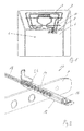
- Fig. 2 shows the sensor system 10 according to the invention consists essentially of a fastener 8, a sensor tube 12, a spring element 14, a sensor 16 and a supply line 18.
- the fastening element 8 and the sensor tube 12 form a substantially rigid unit, which is such protrudes into the cooking chamber, which projects into the cooking chamber 1 a closed end 20 of the sensor tube 12.
- An open end 22 of the sensor tube 12 protrudes through the rear wall 6.
- the protective sleeve 16 a protective ceramic tube 24th forms a stop or collar, from which the spring element extends in a spiral around the supply line 18.
- An end of the spring element 14 lying opposite the sensor 16 has a holding element 26 with which the spring element 14 is fastened to the sensor tube 12.
- To the sensor tube 12 has a holding section 28 into which the holding element 26 engages in a corresponding manner.
- Fig. 3 shows the spring element 14, which consists essentially of a first portion which extends in a spiral, wherein the diameter of the spiral-shaped cross section is about 1.5 mm.
- the holding element 26 adjoining the spiral-shaped section is bent in such a way that an actuating element 30, the holding element 26 is guided out of the holding section 28 of the sensor tube 12 by pressing with the finger, and thus the spring element 14 can be removed from the probe tube 12.
- the assembly of the spring element takes place substantially in the reverse order, wherein the spiral portion of the spring element 14 is inserted linearly to the line of symmetry of the sensor tube 12 in the sensor tube 12 until the stop of the support member 26 at the open end 22 of the sensor tube 12.
- the holding member 26 pivots about the outer radius of the sensor tube 12.
- the spring element 14 can be further inserted until the sensor reaches its installation position at the closed end 20. In this position, the holding element 26 snaps resiliently into the holding portion 28 of the sensor tube 12 and hooks behind.
- the length (L) of the spring element 14 is chosen so that in the installed position of the sensor 16 is subjected to force against the closed end 20 of the sensor tube 12 is pressed.
- Fig. 4 shows the sensor tube 12, which is preferably made of stainless steel.
- One end of the probe tube 12 is closed by a stamping process so that the closed end 20 of the probe tube 12 is both vapor and microwave tight.
- the still open end 22 of the sensor tube 12 forms the inlet for the spring element 14, which carries the sensor 16 and the supply line 18.
- a holding portion 28 is formed, which serves to receive the holding element 26 of the spring element 14.
- the holding portion 28 is inserted into the sensor tube 12 by an oblique saw cut.
- This holding section may alternatively be formed as an opening, a bore or any further variant of an undercut.
Landscapes
- Engineering & Computer Science (AREA)
- Chemical & Material Sciences (AREA)
- Combustion & Propulsion (AREA)
- Mechanical Engineering (AREA)
- General Engineering & Computer Science (AREA)
- Physics & Mathematics (AREA)
- General Physics & Mathematics (AREA)
- Electric Ovens (AREA)
- Measuring Temperature Or Quantity Of Heat (AREA)
Abstract
Description
- Die Erfindung betrifft ein Sensorsystem für ein Gargerät nach dem Oberbegriff des Anspruchs 1 sowie ein Fühlerrohr zur Aufnahme einer Sensoreinheit nach Anspruch 9.
- Herkömmliche Sensorvorrichtungen zur Ermittlung der Temperatur in Backöfen umfassen einen Sensor mit einem elektrischen Widerstand, welcher in ein Keramikrohr eingebettet ist. An einer Versorgungsleitung hängend, wird das Keramikrohr in ein Fühlerrohr eingeschoben und mittels Schrauben oder Klemmelementen fixiert. Nachteilig an den bekannten Lösungen ist, dass der Sensor relativ undefiniert im Fühlerrohr sitzt und durch Erschütterungen beim Transport oder Vibrationen über die Lebensdauer im Fühlerrohr wandern kann. Zudem sind heutige Sensorvorrichtungen nur sehr aufwendig zu demontieren.
- Aufgabe der Erfindung ist es, bekannte Sensorsysteme zu verbessern. Eine mögliche Verbesserung ist es, die Positionierung des Sensors im Fühlerrohr zu verbessern und eine Demontage der Sensoren zu ermöglichen. Die Aufgabe wird erfindungsgemäß durch die Merkmale der unabhängigen Patentansprüche gelöst, während vorteilhafte Ausgestaltungen und Weiterbildungen der Erfindung den Unteransprüchen entnommen werden können.
- Die Erfindung geht aus von einem Sensorsystem für ein Gargerät mit einem Befestigungselement zur Aufnahme eines Fühlerrohrs, indem ein Sensor sowie zumindest eine mit dem Sensor kontaktierte Versorgungsleitung angeordnet ist.
- Es wird vorgeschlagen, dass der Sensor im Fühlerrohr mittels eines Federelements positioniert ist. Unter einem Sensorsystem für ein Gargerät soll insbesondere eine Baugruppe verstanden werden, welche geeignet ist, die Temperatur im Garraum eines Backofens zu erfassen und an eine nicht zum Sensorsystem gehörige Elektronik weiterzuleiten. Zum Sensorsystem zählt demnach auch ein Befestigungselement, wie z.B. ein Grillheizkörperflansch, der geeignet ist die Gesamtheit der Bauteile des Sensorsystems in Einbaulage zum Garraum zu positionieren. Dazu ist das Befestigungselement vorzugsweise an der Garraumrückwand angebracht. Unter einem Fühlerrohr soll insbesondere ein Gehäuse verstanden werden, welches derart ausgebildet ist, dass es den Sensor im Inneren aufnimmt und dem Garraum zuführt. Durch diese Anordnung ist sichergestellt, dass die im Garraum wirkende Temperatur an den Sensor weitergegeben wird, wobei der Sensor gleichzeitig vor Wrasen sowie Verschmutzung geschützt angeordnet ist. Unter einem Sensor soll insbesondere ein elektrischer Widerstand verstanden werden, der geeignet ist, elektrische Signale in Abhängigkeit einer auf ihn wirkenden Temperatur zu beeinflussen. Zudem besteht der Sensor aus einer zumeist keramisch ausgeführten Schutzhülle, welche die elektronischen Komponenten schützt, wobei der zwischen Widerstand und Keramikrohr entstehende Hohlraum zur besseren Leitfähigkeit mit Zement ausgefüllt ist. Unter einer Versorgungsleitung soll insbesondere eine elektrische Leitung verstanden werden, welche geeignet ist, Signale bzw. eine elektrische Spannung an den Sensor zu leiten und ein durch den Sensor generiertes Signal in Form einer Spannung an eine elektrische Komponente zu leiten. Unter einem Federelement soll insbesondere ein nicht starres Element verstanden werden, welches derart ausgebildet ist, den Sensor im Fühlerrohr derart zu positionieren, dass dieser stets an der bestmöglichen Position gehaltert ist und zudem zerstörungsfrei demontiert werden kann.
- Vorzugsweise umgibt das Federelement den Sensor und/oder die Versorgungsleitung zumindest abschnittsweise spiralförmig. Unter spiralförmig soll insbesondere verstanden werden, dass das Federelement rotierend um den Sensor und/oder die Versorgungsleitung gewickelt ist. Alternativ dazu ist das Federelement bereits spiralförmig ausgebildet und der Sensor mit der angebrachten Versorgungsleitung wird in das Federelement eingeschoben. Dabei kann der Sensor bzw. das Keramikrohr als Anschlag in Einschubrichtung dienen. Vorteilhaft an dieser Ausgestaltung ist, dass ein derart umwickelter Sensor und/oder die Versorgungsleitung einen Knickschutz vor unbeabsichtigtem Abknicken der Versorgungsleitung sowie einen Kantenschutz vor scharfen Gehäuseabschnitten erhält.
- Vorteilhafterweise ist das Federelement zumindest abschnittsweise aus einem federelastischen Element, wie z.B. Blech, Draht und/oder Kunststoff ausgebildet. Vorteilhafterweise halten diese Materialien den temperaturbedingten Anforderungen Stand.
- Vorzugsweise weist das Fühlerrohr ein offenes Ende und ein geschlossenes Ende auf. Dieser Aufbau ermöglicht dem Fühlerrohr, dass es einerseits an seiner geschlossenen Seite gegenüber dem Garraum abgedichtet ist an und an seiner offenen Seite geeignet ist den Sensor sowie die Versorgungsleitung aufzunehmen. Das geschlossene Ende wir vorzugsweise mittels einer Quetschung des Fühlerrohrs erzeugt, kann alternativ aber auch verschweißt, verschraubt, oder ähnliches sein.
- Vorzugsweise drückt das Federelement den Sensor in Einbaulage kraftbeaufschlagt in Richtung des geschlossenen Endes in das Fühlerrohr. Vorteilhaft an dieser Ausgestaltung ist, dass stets sichergestellt ist, dass der Temperaturfühler am Ende des Fühlerrohrs anliegt und seine Position über die Lebensdauer nicht verändert. Durch ein derartiges Federelement wird die Position auch dann sichergestellt, wenn eine Erschütterung beispielsweise durch den Transport auf das Sensorsystem einwirkt.
- Vorzugsweise weist das Fühlerrohr einen Halteabschnitt auf. Unter einem Halteabschnitt soll insbesondere ein Durchbruch, eine Bohrung, ein Hinterschnitt oder eine ähnliche Verformungen des Fühlerrohrs verstanden werden, welche geeignet ist, einen Haltebereich auszubilden, indem ein im Wesentlichen hakenförmiges Element eingreifen kann. Eine bevorzugte Position des Halteabschnitts befindet sich im Bereich des offenen Endes am Fühlerrohr.
- Vorzugsweise ist das Fühlerrohr mittels eines Schweiß- und/oder Press- und/oder Schraubverfahrens an dem Befestigungselement gehaltert. Durch diese oder ähnliche Fügeverfahren ist sichergestellt, dass das Fühlerrohr fest am Gargerät, insbesondere zum Garraum hin angeordnet ist. Ein bevorzugtes Befestigungselement ist der Grillheizkörperflansch, da dieser im Deckenbereich des Garraums angeordnet ist, und die Grillheizelemente trägt, welche unter anderem durch das Sensorsystem angesteuert werden.
- Vorzugsweise ist das Fühlerrohr dampf- und/oder mikrowellendicht ausgeführt. Durch eine derartige Ausgestaltung des Fühlerrohrs ist ein Einsatz in einem Dampf- und/oder Mikrowellengerät möglich. Die Dichtheit gegenüber Dampf bzw. Mikrowellen wird durch das geschlossene Ende des Fühlerrohrs erzielt, wobei das geschlossene Ende vorzugsweise mittels einer Quetschung des Fühlerrohrs erzeugt ist. Alternativ zu einem rohrförmgien Halbzeug des Fühlerrohrs, ist auch jede weitere Halbzeugvariante bzw. jedes Herstellverfahren von der Erfindung umfasst, welches geeignet ist ein Gehäuseelement auszubilden. Mitunter ist auch ein durch einen Tiefziehprozess hergestelltes Fühlerrohr möglich.
- Vorzugsweise ist am Federelement ein Halteelement ausgebildet. Das Halteelement befestigt das Federelement am Fühlerrohr, insbesondere am Halteabschnitt des Fühlerrohrs. Vorteilhafterweise ist das Halteelement hakenförmig aus dem Material des Federelements gebildet. Dieses bevorzugte Ausführungsbeispiel ermöglicht, dass das Federelement, welches den Sensor und die Versorgungsleitung trägt, in das Fühlerrohr eingeführt wird und in der Endposition mittels des Halteelements am Fühlerrohr fixierbar ist. Eine besonders gute Positionierung des Sensors im Fühlerrohr wird dadurch erzeugt, dass die Länge (L) des Federelements länger ist als der Innenbereich des Fühlerrohrs, so dass eine Art Vorspannung in Richtung der Einschubrichtung des Federelements in das Fühlerrohr entsteht, welches den Sensor kraftbeaufschlagt gegen das geschlossenen Ende des Fühlerrohrs presst.
- Fühlerrohr zur Aufnahme eines Sensors, insbesondere eines Temperaturfühlers für ein Gargerät, wobei das Fühlerrohr einen Halteabschnitt, vorzugsweise in Form eines Durchbruchs, einer Bohrung oder eines Hinterschnitts, zur Aufnahme eines Federelements aufweist.
- Weitere Merkmale der Erfindung ergeben sich aus den Figuren und der Figurenbeschreibung. Die vorstehend in der Beschreibung genannten Merkmale und Merkmalskombinationen sowie die nachfolgend in der Figurenbeschreibung genannten und/oder in den Figuren alleine gezeigten Merkmale und Merkmalskombinationen sind nicht nur in der jeweils angegebenen Kombination, sondern auch in anderen Kombinationen oder in Alleinstellung verwendbar, ohne den Rahmen der Erfindung zu verlassen. Es sind somit auch Ausführungsbeispiele von der Erfindung als umfasst und offenbart anzusehen, die in den schematischen Figuren nicht explizit gezeigt und erläutert sind, jedoch durch separierte Merkmalskombinationen aus den erläuterten Ausführungen hervorgehen und erzeugbar sind. Dabei zeigt:
- Fig. 1
- eine schematische perspektivische Darstellung eines Ausführungsbeispiels des Sensorsystems im Garraum;
- Fig. 2
- eine schematische perspektivische Darstellung eines Sensorsystems;
- Fig. 3
- eine schematische perspektivische Darstellung eines Federelements; und
- Fig. 4
- eine schematische perspektivische Darstellung eines Fühlerrohrs.
- Ein nicht näher dargestellter an sich bekannter Backofen weist gemäß
Fig. 1 einen frontseitig verschließbaren und im Wesentlichen quaderförmigen Garraum 1 auf, der frontseitig durch eine drehbar angelenkte Backofentür (nicht gezeigt) verschließbar ist. Unmittelbar unterhalb einer Deckwand 2 des Garraums 1 ist ein Strahlungsheizkörper 4 in Ausgestaltung eines Grillheizkörpers gehaltert, der sich nahezu über die gesamte Fläche der Deckwand 2 erstreckt. Zur Halterung des Strahlungsheizkörpers 4 dient ein an der Rückwand 6 des Garraums 1 angeordnetes Befestigungselement 8 in Ausgestaltung eines Grillheizkörperflansches. An dem Befestigungselement 8 ist zudem zumindest ein Sensorsystem 10 angeordnet. Das Sensorsystem 10 dient zur Aufnahme der Temperatur im Garraum 1 oder zur Aufnahme der Temperatur, welche vom Strahlungsheizkörper 5 abgegeben wird. -
Fig. 2 zeigt das erfindungsgemäße Sensorsystem 10. Das Sensorsystem 10 besteht im Wesentlichen aus einem Befestigungselement 8, einem Fühlerrohr 12, einem Federelement 14, einem Sensor 16 und einer Versorgungsleitung 18. Dabei bilden das Befestigungselement 8 und das Fühlerrohr 12 eine im Wesentlichen starre Einheit, welche derart in dem Garraum ragt, das ein geschlossenes Ende 20 des Fühlerrohrs 12 in den Garraum 1 ragt. Ein offenes Ende 22 des Fühlerrohrs 12 ragt durch die Rückwand 6. Zur Montage des Sensors 6 mit seiner zumindest einen Versorgungsleitung 18 wird dieser vor dem Einschieben in das Fühlerrohr 12 in der Art mit dem Federelement 14 verbunden, das ein den Sensor 16 schützendes Keramikrohr 24 einen Anschlag bzw. Kragen bildet, von dem aus sich das Federelement spiralförmig um die Versorgungsleitung 18 erstreckt. Ein dem Sensor 16 gegenüberliegendes Ende des Federelements 14 weist dabei ein Halteelement 26 auf, mit dem das Federelement 14 am Fühlerrohr 12 befestigt ist. Dazu weist das Fühlerrohr 12 einen Halteabschnitt 28 auf, in den das Halteelement 26 korrespondierend eingreift. -
Fig. 3 zeigt das Federelement 14, welches im Wesentlichen aus einem ersten Abschnitt besteht, der sich spiralförmig erstreckt, wobei der Durchmesser des spiralförmigen Querschnitts ca. 1,5 mm ist. Das sich am spiralförmigen Abschnitt anschließende Halteelement 26 ist in der Art gebogen, dass durch Drücken mit dem Finger ein Betätigungselement 30, das Halteelement 26 aus dem Halteabschnitt 28 des Fühlerrohrs 12 gelenkt wird und somit das Federelement 14 dem Fühlerrohr 12 entnommen werden kann. Die Montage des Federelements erfolgt im Wesentlichen in umgekehrter Reihenfolge, wobei der spiralförmige Abschnitt des Federelements 14 linear zur Symmetrielinie des Fühlerrohrs 12 in das Fühlerrohr 12 eingeführt wird, bis der Anschlag des Halteelements 26 am offenen Ende 22 des Fühlerrohrs 12 erfolgt. Durch leichtes Drücken des federelastischen Betätigungselements 30 schwenkt das Halteelement 26 über den Außenradius des Fühlerrohrs 12. Nun kann das Federelement 14 weiter eingeschoben werden, bis der Sensor seine Einbaulage am geschlossenen Ende 20 erreicht. In dieser Position schnappt das Halteelement 26 federelastisch in den Halteabschnitt 28 des Fühlerrohrs 12 ein und hinterhakt. Die Länge (L) des Federelements 14 ist dabei so gewählt, dass in Einbaulage der Sensor 16 kraftbeaufschlagt gegen das geschlossene Ende 20 des Fühlerrohrs 12 gepresst wird. -
Fig. 4 zeigt das Fühlerrohr 12, welches vorzugsweise aus Edelstahl gefertigt ist. Ein Ende des Fühlerrohrs 12 ist durch ein Prägeverfahren geschlossen, so dass das geschlossene Ende 20 des Fühlerrohrs 12 sowohl dampf- als auch mikrowellendicht ist. Das weiterhin offene Ende 22 des Fühlerrohrs 12 bildet den Einlass für das Federelement 14, welches den Sensor 16 sowie die Versorgungsleitung 18 trägt. Am Fühlerrohr 12 ist ein Halteabschnitt 28 ausgebildet, welcher zur Aufnahme des Halteelements 26 des Federelements 14 dient. In dem vorliegenden Ausführungsbeispiel ist der Halteabschnitt 28 durch einen schräg verlaufenden Sägeschnitt in das Fühlerrohr 12 eingebracht. Dieser Halteabschnitt kann alternativ als ein Durchbruch, eine Bohrung oder jede weitere Variante eines Hinterschnitts ausgebildet sein. - Für den Fachmann ist erkennbar, dass die Erfindung nicht auf das dargestellte Ausführungsbeispiel beschränkt ist, sondern dass eine Vielzahl von Varianten und Abwandlungen ebenfalls davon umfasst sind.
-
- 1
- Garraum
- 2
- Deckwand
- 4
- Strahlungsheizkörper
- 6
- Rückwand
- 8
- Befestigungselement
- 10
- Sensorsystem
- 12
- Fühlerrohr
- 14
- Federelement
- 16
- Sensor
- 18
- Versorgungsleitung
- 20
- geschlossenes Ende des Fühlerrohrs 12
- 22
- offenes Ende des Fühlerrohrs 12
- 24
- Keramikrohr
- 26
- Halteelement
- 28
- Halteabschnitt
- 30
- Betätigungselement
- L
- Länge des Federelements 14
Claims (10)
- Sensorsystem für ein Gargerät mit einem Befestigungselement (8) zur Aufnahme eines Fühlerrohrs (12), indem ein Sensor (16) sowie zumindest eine mit dem Sensor (16) kontaktierte Versorgungsleitung (18) angeordnet ist, dadurch gekennzeichnet, dass der Sensor (16) im Fühlerrohr (12) durch ein Federelement (14) positioniert ist.
- Sensorsystem nach Anspruch 1, dadurch gekennzeichnet, dass das Federelement (14) den Sensor (16) und/oder die Versorgungsleitung (18) zumindest abschnittsweise spiralförmig umgibt.
- Sensorsystem nach einem der vorangegangenen Ansprüche, dadurch gekennzeichnet, dass das Federelement (14) zumindest abschnittsweise aus einem federelastischen Draht und/oder Kunststoff gebildet ist.
- Sensorsystem nach einem der vorangegangenen Ansprüche, dadurch gekennzeichnet, dass das Fühlerrohr (12) ein geschlossenes Ende (20) und ein offenes Ende (22) aufweist.
- Sensorsystem nach einem der vorangegangenen Ansprüche, dadurch gekennzeichnet, dass das Federelement (14) den Sensor (16) in Einbaulage kraftbeaufschlagt in Richtung des geschlossenes Endes (20) in das Fühlerrohr (12) drückt.
- Sensorsystem nach einem der vorangegangenen Ansprüche, dadurch gekennzeichnet, dass das Fühlerrohr (12) vorzugsweise im Bereich des offenen Endes (22) einem Halteabschnitt (28) aufweist.
- Sensorsystem nach einem der vorangegangenen Ansprüche, dadurch gekennzeichnet, dass das Fühlerrohr (12) mittels eines Schweiß- und/oder Press- und/oder Schraubverfahrens an dem Befestigungselement (8) gehaltert ist, wobei das Befestigungselement (8) insbesondere als Grillheizkörperflansch ausgeführt ist.
- Sensorsystem nach einem der vorangegangenen Ansprüche, dadurch gekennzeichnet, dass das Fühlerrohr (12) dampf- und/oder mikrowellendicht ausgeführt ist.
- Sensoreinheit nach einem der vorangegangenen Ansprüche, dadurch gekennzeichnet, dass am Federelement (14) ein Halteelement (26) ausgebildet ist, mit dem das Federelement (14) am Fühlerrohr (12), insbesondere am Halteabschnitt (28) des Fühlerrohrs (12) befestigt ist.
- Fühlerrohr zur Aufnahme eines Sensors (16), insbesondere eines Temperaturfühlers für ein Gargerät, dadurch gekennzeichnet, dass das Fühlerrohr (12) einen Halteabschnitt (28) zur Aufnahme eines Federelements (14) aufweist.
Priority Applications (1)
| Application Number | Priority Date | Filing Date | Title |
|---|---|---|---|
| PL15181897T PL2993411T3 (pl) | 2014-09-03 | 2015-08-21 | Układ czujników do urządzenia do gotowania |
Applications Claiming Priority (1)
| Application Number | Priority Date | Filing Date | Title |
|---|---|---|---|
| DE102014217630.1A DE102014217630A1 (de) | 2014-09-03 | 2014-09-03 | Sensorsystem für ein Gargerät |
Publications (2)
| Publication Number | Publication Date |
|---|---|
| EP2993411A1 true EP2993411A1 (de) | 2016-03-09 |
| EP2993411B1 EP2993411B1 (de) | 2019-10-23 |
Family
ID=53938236
Family Applications (1)
| Application Number | Title | Priority Date | Filing Date |
|---|---|---|---|
| EP15181897.8A Active EP2993411B1 (de) | 2014-09-03 | 2015-08-21 | Sensorsystem für ein gargerät |
Country Status (3)
| Country | Link |
|---|---|
| EP (1) | EP2993411B1 (de) |
| DE (1) | DE102014217630A1 (de) |
| PL (1) | PL2993411T3 (de) |
Citations (5)
| Publication number | Priority date | Publication date | Assignee | Title |
|---|---|---|---|---|
| DE1565721A1 (de) * | 1966-07-28 | 1970-07-16 | Micko Oswald Walter | Geraet zum Regeln der Aufladung eines Waermespeichers,insbesondere eines Nachtstromspeicherofens |
| DE8328681U1 (de) * | 1983-10-05 | 1984-01-05 | Stiebel Eltron Gmbh & Co Kg, 3450 Holzminden | Schutzrohr eines warmwasserbereiters |
| US5321381A (en) * | 1991-11-26 | 1994-06-14 | E.G.O. Elektro-Gerate Blanc U. Fischer | Base for an electromechanical functional unit |
| US20010020612A1 (en) * | 1998-07-31 | 2001-09-13 | Josef Wurm | Baking oven with temperature sensor |
| DE10342761A1 (de) * | 2003-09-16 | 2005-04-21 | Bsh Bosch Siemens Hausgeraete | Sensorvorrichtung für ein Gargerät und Verfahren zur Herstellung derselben |
Family Cites Families (2)
| Publication number | Priority date | Publication date | Assignee | Title |
|---|---|---|---|---|
| US2890429A (en) * | 1955-10-11 | 1959-06-09 | King Sceley Corp | Electrical temperature sensing device |
| DE3210180C1 (de) * | 1982-03-19 | 1983-10-27 | Bosch-Siemens Hausgeräte GmbH, 7000 Stuttgart | Sicherungsvorrichtung für das Fühlerelement, z.B. Kapillarrohr, eines temperaturabhängigen Schalters oder Reglers für Herde |
-
2014
- 2014-09-03 DE DE102014217630.1A patent/DE102014217630A1/de not_active Withdrawn
-
2015
- 2015-08-21 PL PL15181897T patent/PL2993411T3/pl unknown
- 2015-08-21 EP EP15181897.8A patent/EP2993411B1/de active Active
Patent Citations (5)
| Publication number | Priority date | Publication date | Assignee | Title |
|---|---|---|---|---|
| DE1565721A1 (de) * | 1966-07-28 | 1970-07-16 | Micko Oswald Walter | Geraet zum Regeln der Aufladung eines Waermespeichers,insbesondere eines Nachtstromspeicherofens |
| DE8328681U1 (de) * | 1983-10-05 | 1984-01-05 | Stiebel Eltron Gmbh & Co Kg, 3450 Holzminden | Schutzrohr eines warmwasserbereiters |
| US5321381A (en) * | 1991-11-26 | 1994-06-14 | E.G.O. Elektro-Gerate Blanc U. Fischer | Base for an electromechanical functional unit |
| US20010020612A1 (en) * | 1998-07-31 | 2001-09-13 | Josef Wurm | Baking oven with temperature sensor |
| DE10342761A1 (de) * | 2003-09-16 | 2005-04-21 | Bsh Bosch Siemens Hausgeraete | Sensorvorrichtung für ein Gargerät und Verfahren zur Herstellung derselben |
Also Published As
| Publication number | Publication date |
|---|---|
| DE102014217630A1 (de) | 2016-03-03 |
| EP2993411B1 (de) | 2019-10-23 |
| PL2993411T3 (pl) | 2020-04-30 |
Similar Documents
| Publication | Publication Date | Title |
|---|---|---|
| EP2377452A1 (de) | Pumpe mit Heizeinrichtung | |
| DE102011084229A1 (de) | Temperatursensor mit integriertem Toleranzausgleich und Haltekraft | |
| EP0870192A1 (de) | Messeinrichtung | |
| EP3164591B1 (de) | Regelventil zum anbau an einen kfz-motor | |
| EP0498386B1 (de) | Temperaturfühler und Verfahren zu seiner Herstellung | |
| EP4123266A1 (de) | Ultraschalldurchflussmesser | |
| DE102017200683A1 (de) | Temperatursensor für den Verdampfer einer Kraftfahrzeug-Klimaanlage | |
| DE102013002750A1 (de) | Türgriff für ein Kraftfahrzeug | |
| DE4411191C2 (de) | Kältemittelkompressoranordnung | |
| DE102014207562A1 (de) | Pumpe | |
| EP2993411B1 (de) | Sensorsystem für ein gargerät | |
| DE3305232A1 (de) | Vorrichtung zum entnehmen einer heissen gasprobe aus einem gasvolumen | |
| DE102009039778A1 (de) | Heizelement | |
| EP1339260B1 (de) | Temperaturfühler | |
| DE19716010C1 (de) | Elektrischer Mantelrohrheizkörper mit integriertem Temperaturfühler | |
| DE102016111258A1 (de) | Heizpatrone mit einem Schutzrohr | |
| EP2336645B1 (de) | Haushaltsgerät mit einer Dichtungseinrichtung | |
| DE10319318B4 (de) | Schalldämpfer für ein Fahrzeugtemperiergerät | |
| EP1731850B1 (de) | Flanschloser Kunststoff-Boiler | |
| EP1331076A1 (de) | Vorrichtung zur Befestigung eines elektrischen Heizkörpers auf der Spritzdüse von Spritzgiesswerkzeugen | |
| DE202008018089U1 (de) | Temperaturfühler für Turbolader | |
| DE102019132420A1 (de) | Tauchsieder, System mit einem Tauchsieder und Verfahren zum Betrieb des Systems | |
| DE102016120793B4 (de) | Heizgerät | |
| DE102017130673A1 (de) | Regelventil für einen Verbrennungsmotor und Verfahren zur Regelung eines Regelventils | |
| DE102015224472B4 (de) | Drucksensor zur Erfassung eines Drucks eines fluiden Mediums |
Legal Events
| Date | Code | Title | Description |
|---|---|---|---|
| PUAI | Public reference made under article 153(3) epc to a published international application that has entered the european phase |
Free format text: ORIGINAL CODE: 0009012 |
|
| AK | Designated contracting states |
Kind code of ref document: A1 Designated state(s): AL AT BE BG CH CY CZ DE DK EE ES FI FR GB GR HR HU IE IS IT LI LT LU LV MC MK MT NL NO PL PT RO RS SE SI SK SM TR |
|
| AX | Request for extension of the european patent |
Extension state: BA ME |
|
| 17P | Request for examination filed |
Effective date: 20160909 |
|
| RBV | Designated contracting states (corrected) |
Designated state(s): AL AT BE BG CH CY CZ DE DK EE ES FI FR GB GR HR HU IE IS IT LI LT LU LV MC MK MT NL NO PL PT RO RS SE SI SK SM TR |
|
| STAA | Information on the status of an ep patent application or granted ep patent |
Free format text: STATUS: EXAMINATION IS IN PROGRESS |
|
| 17Q | First examination report despatched |
Effective date: 20181214 |
|
| GRAP | Despatch of communication of intention to grant a patent |
Free format text: ORIGINAL CODE: EPIDOSNIGR1 |
|
| STAA | Information on the status of an ep patent application or granted ep patent |
Free format text: STATUS: GRANT OF PATENT IS INTENDED |
|
| INTG | Intention to grant announced |
Effective date: 20190703 |
|
| GRAS | Grant fee paid |
Free format text: ORIGINAL CODE: EPIDOSNIGR3 |
|
| GRAA | (expected) grant |
Free format text: ORIGINAL CODE: 0009210 |
|
| STAA | Information on the status of an ep patent application or granted ep patent |
Free format text: STATUS: THE PATENT HAS BEEN GRANTED |
|
| AK | Designated contracting states |
Kind code of ref document: B1 Designated state(s): AL AT BE BG CH CY CZ DE DK EE ES FI FR GB GR HR HU IE IS IT LI LT LU LV MC MK MT NL NO PL PT RO RS SE SI SK SM TR |
|
| REG | Reference to a national code |
Ref country code: GB Ref legal event code: FG4D Free format text: NOT ENGLISH |
|
| REG | Reference to a national code |
Ref country code: CH Ref legal event code: EP |
|
| REG | Reference to a national code |
Ref country code: IE Ref legal event code: FG4D Free format text: LANGUAGE OF EP DOCUMENT: GERMAN |
|
| REG | Reference to a national code |
Ref country code: DE Ref legal event code: R096 Ref document number: 502015010714 Country of ref document: DE |
|
| REG | Reference to a national code |
Ref country code: AT Ref legal event code: REF Ref document number: 1194069 Country of ref document: AT Kind code of ref document: T Effective date: 20191115 |
|
| REG | Reference to a national code |
Ref country code: NL Ref legal event code: MP Effective date: 20191023 |
|
| REG | Reference to a national code |
Ref country code: LT Ref legal event code: MG4D |
|
| PG25 | Lapsed in a contracting state [announced via postgrant information from national office to epo] |
Ref country code: ES Free format text: LAPSE BECAUSE OF FAILURE TO SUBMIT A TRANSLATION OF THE DESCRIPTION OR TO PAY THE FEE WITHIN THE PRESCRIBED TIME-LIMIT Effective date: 20191023 Ref country code: LV Free format text: LAPSE BECAUSE OF FAILURE TO SUBMIT A TRANSLATION OF THE DESCRIPTION OR TO PAY THE FEE WITHIN THE PRESCRIBED TIME-LIMIT Effective date: 20191023 Ref country code: PT Free format text: LAPSE BECAUSE OF FAILURE TO SUBMIT A TRANSLATION OF THE DESCRIPTION OR TO PAY THE FEE WITHIN THE PRESCRIBED TIME-LIMIT Effective date: 20200224 Ref country code: SE Free format text: LAPSE BECAUSE OF FAILURE TO SUBMIT A TRANSLATION OF THE DESCRIPTION OR TO PAY THE FEE WITHIN THE PRESCRIBED TIME-LIMIT Effective date: 20191023 Ref country code: GR Free format text: LAPSE BECAUSE OF FAILURE TO SUBMIT A TRANSLATION OF THE DESCRIPTION OR TO PAY THE FEE WITHIN THE PRESCRIBED TIME-LIMIT Effective date: 20200124 Ref country code: NO Free format text: LAPSE BECAUSE OF FAILURE TO SUBMIT A TRANSLATION OF THE DESCRIPTION OR TO PAY THE FEE WITHIN THE PRESCRIBED TIME-LIMIT Effective date: 20200123 Ref country code: BG Free format text: LAPSE BECAUSE OF FAILURE TO SUBMIT A TRANSLATION OF THE DESCRIPTION OR TO PAY THE FEE WITHIN THE PRESCRIBED TIME-LIMIT Effective date: 20200123 Ref country code: FI Free format text: LAPSE BECAUSE OF FAILURE TO SUBMIT A TRANSLATION OF THE DESCRIPTION OR TO PAY THE FEE WITHIN THE PRESCRIBED TIME-LIMIT Effective date: 20191023 Ref country code: LT Free format text: LAPSE BECAUSE OF FAILURE TO SUBMIT A TRANSLATION OF THE DESCRIPTION OR TO PAY THE FEE WITHIN THE PRESCRIBED TIME-LIMIT Effective date: 20191023 Ref country code: NL Free format text: LAPSE BECAUSE OF FAILURE TO SUBMIT A TRANSLATION OF THE DESCRIPTION OR TO PAY THE FEE WITHIN THE PRESCRIBED TIME-LIMIT Effective date: 20191023 |
|
| PG25 | Lapsed in a contracting state [announced via postgrant information from national office to epo] |
Ref country code: IS Free format text: LAPSE BECAUSE OF FAILURE TO SUBMIT A TRANSLATION OF THE DESCRIPTION OR TO PAY THE FEE WITHIN THE PRESCRIBED TIME-LIMIT Effective date: 20200224 Ref country code: HR Free format text: LAPSE BECAUSE OF FAILURE TO SUBMIT A TRANSLATION OF THE DESCRIPTION OR TO PAY THE FEE WITHIN THE PRESCRIBED TIME-LIMIT Effective date: 20191023 Ref country code: RS Free format text: LAPSE BECAUSE OF FAILURE TO SUBMIT A TRANSLATION OF THE DESCRIPTION OR TO PAY THE FEE WITHIN THE PRESCRIBED TIME-LIMIT Effective date: 20191023 |
|
| PG25 | Lapsed in a contracting state [announced via postgrant information from national office to epo] |
Ref country code: AL Free format text: LAPSE BECAUSE OF FAILURE TO SUBMIT A TRANSLATION OF THE DESCRIPTION OR TO PAY THE FEE WITHIN THE PRESCRIBED TIME-LIMIT Effective date: 20191023 |
|
| REG | Reference to a national code |
Ref country code: DE Ref legal event code: R097 Ref document number: 502015010714 Country of ref document: DE |
|
| PG2D | Information on lapse in contracting state deleted |
Ref country code: IS |
|
| PG25 | Lapsed in a contracting state [announced via postgrant information from national office to epo] |
Ref country code: RO Free format text: LAPSE BECAUSE OF FAILURE TO SUBMIT A TRANSLATION OF THE DESCRIPTION OR TO PAY THE FEE WITHIN THE PRESCRIBED TIME-LIMIT Effective date: 20191023 Ref country code: DK Free format text: LAPSE BECAUSE OF FAILURE TO SUBMIT A TRANSLATION OF THE DESCRIPTION OR TO PAY THE FEE WITHIN THE PRESCRIBED TIME-LIMIT Effective date: 20191023 Ref country code: EE Free format text: LAPSE BECAUSE OF FAILURE TO SUBMIT A TRANSLATION OF THE DESCRIPTION OR TO PAY THE FEE WITHIN THE PRESCRIBED TIME-LIMIT Effective date: 20191023 Ref country code: CZ Free format text: LAPSE BECAUSE OF FAILURE TO SUBMIT A TRANSLATION OF THE DESCRIPTION OR TO PAY THE FEE WITHIN THE PRESCRIBED TIME-LIMIT Effective date: 20191023 Ref country code: IS Free format text: LAPSE BECAUSE OF FAILURE TO SUBMIT A TRANSLATION OF THE DESCRIPTION OR TO PAY THE FEE WITHIN THE PRESCRIBED TIME-LIMIT Effective date: 20200223 |
|
| PLBE | No opposition filed within time limit |
Free format text: ORIGINAL CODE: 0009261 |
|
| STAA | Information on the status of an ep patent application or granted ep patent |
Free format text: STATUS: NO OPPOSITION FILED WITHIN TIME LIMIT |
|
| PG25 | Lapsed in a contracting state [announced via postgrant information from national office to epo] |
Ref country code: IT Free format text: LAPSE BECAUSE OF FAILURE TO SUBMIT A TRANSLATION OF THE DESCRIPTION OR TO PAY THE FEE WITHIN THE PRESCRIBED TIME-LIMIT Effective date: 20191023 Ref country code: SM Free format text: LAPSE BECAUSE OF FAILURE TO SUBMIT A TRANSLATION OF THE DESCRIPTION OR TO PAY THE FEE WITHIN THE PRESCRIBED TIME-LIMIT Effective date: 20191023 Ref country code: SK Free format text: LAPSE BECAUSE OF FAILURE TO SUBMIT A TRANSLATION OF THE DESCRIPTION OR TO PAY THE FEE WITHIN THE PRESCRIBED TIME-LIMIT Effective date: 20191023 |
|
| 26N | No opposition filed |
Effective date: 20200724 |
|
| PG25 | Lapsed in a contracting state [announced via postgrant information from national office to epo] |
Ref country code: SI Free format text: LAPSE BECAUSE OF FAILURE TO SUBMIT A TRANSLATION OF THE DESCRIPTION OR TO PAY THE FEE WITHIN THE PRESCRIBED TIME-LIMIT Effective date: 20191023 |
|
| PG25 | Lapsed in a contracting state [announced via postgrant information from national office to epo] |
Ref country code: MC Free format text: LAPSE BECAUSE OF FAILURE TO SUBMIT A TRANSLATION OF THE DESCRIPTION OR TO PAY THE FEE WITHIN THE PRESCRIBED TIME-LIMIT Effective date: 20191023 |
|
| REG | Reference to a national code |
Ref country code: CH Ref legal event code: PL |
|
| PG25 | Lapsed in a contracting state [announced via postgrant information from national office to epo] |
Ref country code: LU Free format text: LAPSE BECAUSE OF NON-PAYMENT OF DUE FEES Effective date: 20200821 Ref country code: LI Free format text: LAPSE BECAUSE OF NON-PAYMENT OF DUE FEES Effective date: 20200831 Ref country code: CH Free format text: LAPSE BECAUSE OF NON-PAYMENT OF DUE FEES Effective date: 20200831 |
|
| REG | Reference to a national code |
Ref country code: BE Ref legal event code: MM Effective date: 20200831 |
|
| PG25 | Lapsed in a contracting state [announced via postgrant information from national office to epo] |
Ref country code: BE Free format text: LAPSE BECAUSE OF NON-PAYMENT OF DUE FEES Effective date: 20200831 Ref country code: IE Free format text: LAPSE BECAUSE OF NON-PAYMENT OF DUE FEES Effective date: 20200821 |
|
| REG | Reference to a national code |
Ref country code: AT Ref legal event code: MM01 Ref document number: 1194069 Country of ref document: AT Kind code of ref document: T Effective date: 20200821 |
|
| PG25 | Lapsed in a contracting state [announced via postgrant information from national office to epo] |
Ref country code: AT Free format text: LAPSE BECAUSE OF NON-PAYMENT OF DUE FEES Effective date: 20200821 |
|
| PG25 | Lapsed in a contracting state [announced via postgrant information from national office to epo] |
Ref country code: MT Free format text: LAPSE BECAUSE OF FAILURE TO SUBMIT A TRANSLATION OF THE DESCRIPTION OR TO PAY THE FEE WITHIN THE PRESCRIBED TIME-LIMIT Effective date: 20191023 Ref country code: CY Free format text: LAPSE BECAUSE OF FAILURE TO SUBMIT A TRANSLATION OF THE DESCRIPTION OR TO PAY THE FEE WITHIN THE PRESCRIBED TIME-LIMIT Effective date: 20191023 |
|
| PG25 | Lapsed in a contracting state [announced via postgrant information from national office to epo] |
Ref country code: MK Free format text: LAPSE BECAUSE OF FAILURE TO SUBMIT A TRANSLATION OF THE DESCRIPTION OR TO PAY THE FEE WITHIN THE PRESCRIBED TIME-LIMIT Effective date: 20191023 |
|
| PGFP | Annual fee paid to national office [announced via postgrant information from national office to epo] |
Ref country code: DE Payment date: 20250831 Year of fee payment: 11 |
|
| PGFP | Annual fee paid to national office [announced via postgrant information from national office to epo] |
Ref country code: TR Payment date: 20250813 Year of fee payment: 11 Ref country code: PL Payment date: 20250814 Year of fee payment: 11 |
|
| PGFP | Annual fee paid to national office [announced via postgrant information from national office to epo] |
Ref country code: GB Payment date: 20250822 Year of fee payment: 11 |
|
| PGFP | Annual fee paid to national office [announced via postgrant information from national office to epo] |
Ref country code: FR Payment date: 20250827 Year of fee payment: 11 |