EP2993294A1 - Verborgener Türbetätiger - Google Patents
Verborgener Türbetätiger Download PDFInfo
- Publication number
- EP2993294A1 EP2993294A1 EP14003055.2A EP14003055A EP2993294A1 EP 2993294 A1 EP2993294 A1 EP 2993294A1 EP 14003055 A EP14003055 A EP 14003055A EP 2993294 A1 EP2993294 A1 EP 2993294A1
- Authority
- EP
- European Patent Office
- Prior art keywords
- door operator
- concealed door
- housing
- concealed
- operating unit
- Prior art date
- Legal status (The legal status is an assumption and is not a legal conclusion. Google has not performed a legal analysis and makes no representation as to the accuracy of the status listed.)
- Withdrawn
Links
- 238000013016 damping Methods 0.000 claims description 14
- 230000001131 transforming effect Effects 0.000 claims description 4
- 229920003266 Leaf® Polymers 0.000 description 13
- 238000004519 manufacturing process Methods 0.000 description 8
- 239000000463 material Substances 0.000 description 4
- 229910052782 aluminium Inorganic materials 0.000 description 3
- XAGFODPZIPBFFR-UHFFFAOYSA-N aluminium Chemical compound [Al] XAGFODPZIPBFFR-UHFFFAOYSA-N 0.000 description 3
- 238000009434 installation Methods 0.000 description 3
- XEEYBQQBJWHFJM-UHFFFAOYSA-N Iron Chemical compound [Fe] XEEYBQQBJWHFJM-UHFFFAOYSA-N 0.000 description 2
- 230000002708 enhancing effect Effects 0.000 description 2
- 229910001060 Gray iron Inorganic materials 0.000 description 1
- 230000001419 dependent effect Effects 0.000 description 1
- 229910052742 iron Inorganic materials 0.000 description 1
- 238000012423 maintenance Methods 0.000 description 1
- 229910052751 metal Inorganic materials 0.000 description 1
- 239000002184 metal Substances 0.000 description 1
- 238000000034 method Methods 0.000 description 1
- 229920003023 plastic Polymers 0.000 description 1
- 239000004033 plastic Substances 0.000 description 1
Images
Classifications
-
- E—FIXED CONSTRUCTIONS
- E05—LOCKS; KEYS; WINDOW OR DOOR FITTINGS; SAFES
- E05F—DEVICES FOR MOVING WINGS INTO OPEN OR CLOSED POSITION; CHECKS FOR WINGS; WING FITTINGS NOT OTHERWISE PROVIDED FOR, CONCERNED WITH THE FUNCTIONING OF THE WING
- E05F3/00—Closers or openers with braking devices, e.g. checks; Construction of pneumatic or liquid braking devices
- E05F3/04—Closers or openers with braking devices, e.g. checks; Construction of pneumatic or liquid braking devices with liquid piston brakes
- E05F3/10—Closers or openers with braking devices, e.g. checks; Construction of pneumatic or liquid braking devices with liquid piston brakes with a spring, other than a torsion spring, and a piston, the axes of which are the same or lie in the same direction
- E05F3/102—Closers or openers with braking devices, e.g. checks; Construction of pneumatic or liquid braking devices with liquid piston brakes with a spring, other than a torsion spring, and a piston, the axes of which are the same or lie in the same direction with rack-and-pinion transmission between driving shaft and piston within the closer housing
-
- E—FIXED CONSTRUCTIONS
- E05—LOCKS; KEYS; WINDOW OR DOOR FITTINGS; SAFES
- E05F—DEVICES FOR MOVING WINGS INTO OPEN OR CLOSED POSITION; CHECKS FOR WINGS; WING FITTINGS NOT OTHERWISE PROVIDED FOR, CONCERNED WITH THE FUNCTIONING OF THE WING
- E05F3/00—Closers or openers with braking devices, e.g. checks; Construction of pneumatic or liquid braking devices
- E05F3/04—Closers or openers with braking devices, e.g. checks; Construction of pneumatic or liquid braking devices with liquid piston brakes
- E05F3/10—Closers or openers with braking devices, e.g. checks; Construction of pneumatic or liquid braking devices with liquid piston brakes with a spring, other than a torsion spring, and a piston, the axes of which are the same or lie in the same direction
- E05F3/104—Closers or openers with braking devices, e.g. checks; Construction of pneumatic or liquid braking devices with liquid piston brakes with a spring, other than a torsion spring, and a piston, the axes of which are the same or lie in the same direction with cam-and-slide transmission between driving shaft and piston within the closer housing
-
- E—FIXED CONSTRUCTIONS
- E05—LOCKS; KEYS; WINDOW OR DOOR FITTINGS; SAFES
- E05F—DEVICES FOR MOVING WINGS INTO OPEN OR CLOSED POSITION; CHECKS FOR WINGS; WING FITTINGS NOT OTHERWISE PROVIDED FOR, CONCERNED WITH THE FUNCTIONING OF THE WING
- E05F3/00—Closers or openers with braking devices, e.g. checks; Construction of pneumatic or liquid braking devices
- E05F3/22—Additional arrangements for closers, e.g. for holding the wing in opened or other position
- E05F3/225—Additional arrangements for closers, e.g. for holding the wing in opened or other position mounted at the bottom of wings, e.g. details related to seals, covers, connections to the wings, embedding in the floor
-
- E—FIXED CONSTRUCTIONS
- E05—LOCKS; KEYS; WINDOW OR DOOR FITTINGS; SAFES
- E05Y—INDEXING SCHEME ASSOCIATED WITH SUBCLASSES E05D AND E05F, RELATING TO CONSTRUCTION ELEMENTS, ELECTRIC CONTROL, POWER SUPPLY, POWER SIGNAL OR TRANSMISSION, USER INTERFACES, MOUNTING OR COUPLING, DETAILS, ACCESSORIES, AUXILIARY OPERATIONS NOT OTHERWISE PROVIDED FOR, APPLICATION THEREOF
- E05Y2201/00—Constructional elements; Accessories therefor
- E05Y2201/10—Covers; Housings
-
- E—FIXED CONSTRUCTIONS
- E05—LOCKS; KEYS; WINDOW OR DOOR FITTINGS; SAFES
- E05Y—INDEXING SCHEME ASSOCIATED WITH SUBCLASSES E05D AND E05F, RELATING TO CONSTRUCTION ELEMENTS, ELECTRIC CONTROL, POWER SUPPLY, POWER SIGNAL OR TRANSMISSION, USER INTERFACES, MOUNTING OR COUPLING, DETAILS, ACCESSORIES, AUXILIARY OPERATIONS NOT OTHERWISE PROVIDED FOR, APPLICATION THEREOF
- E05Y2600/00—Mounting or coupling arrangements for elements provided for in this subclass
- E05Y2600/40—Mounting location; Visibility of the elements
- E05Y2600/41—Concealed
-
- E—FIXED CONSTRUCTIONS
- E05—LOCKS; KEYS; WINDOW OR DOOR FITTINGS; SAFES
- E05Y—INDEXING SCHEME ASSOCIATED WITH SUBCLASSES E05D AND E05F, RELATING TO CONSTRUCTION ELEMENTS, ELECTRIC CONTROL, POWER SUPPLY, POWER SIGNAL OR TRANSMISSION, USER INTERFACES, MOUNTING OR COUPLING, DETAILS, ACCESSORIES, AUXILIARY OPERATIONS NOT OTHERWISE PROVIDED FOR, APPLICATION THEREOF
- E05Y2600/00—Mounting or coupling arrangements for elements provided for in this subclass
- E05Y2600/40—Mounting location; Visibility of the elements
- E05Y2600/46—Mounting location; Visibility of the elements in or on the wing
Definitions
- the present invention regards concealed door operators. Such door operators are used for providing an opening or closing force to a door.
- concealed door operators are well-known from the prior art. Concealed door operators are hidden within a door leaf or a floor or a wall, such that no visible unit needs to be provided on the door.
- Conventional concealed door operators comprise a cast housing and a mounting plate. The housing is connected to the mounting plate via mounting screws. The resulting unit is then installed in a cavity of a door leaf. The final connection of the concealed door operator to the door leaf is realized via the mounting plate.
- the mounting plate comprises holes such that additional mounting screws can be used for fixing the mounting plate to the door leaf. Therefore, a lot of steps are necessary to install the concealed door operator within the door leaf. Further, the manufacturing process of the concealed door operator is very complex a time consuming since two independent elements have to be produced, the housing and the mounting plate.
- a concealed door operator comprising an operating unit and a housing.
- the operating unit is provided within the housing.
- the housing comprises mounting features for mounting the concealed door operator within a door leaf or a floor or a wall.
- the mounting features can be flanges or boreholes for mounting the concealed door operator.
- the mounting features are integrally mounted with the housing. Due to the inventive design, no additional mounting plate needs to be provided. This assists in reducing the components used, and also removing additional process in production.
- the concealed door operator is preferably characterized in that the housing is a cast housing. This allows an integrated manufacturing process of the housing including the mounting features.
- the cast housing can be provided with stiffening means or enhanced wall sections. In general, any cast housing is simple to manufacture and low in cost. Nevertheless, the cast housing is designed to provide maximum durability during the lifecycle of the concealed door operator.
- the housing is realized as aluminum casted or grey cast iron housing.
- the mounting features preferably comprise flanges for fixing the concealed door operator within the door-leaf or the floor or the wall. Therefore, the concealed door operator is installed into a cavity, while the flanges are provided for holding the concealed door operator.
- the flanges seat on surfaces outside the cavity and are preferably fixed to said surfaces.
- the housing has a prismatic shape, wherein the flanges are provided on base faces of the prism.
- Such a design minimizes the room required for mounting the concealed door operator.
- the concealed door operator can therefore be installed into door leafs having a very narrow width.
- the flanges being particularly provided on an edge of the base faces. Further, the flanges are preferably orientated perpendicular to the base faces. This design yet further reduces the required installation room.
- the mounting features preferably comprise through holes.
- the through holes allow to employ mounting elements, especially mounting screws, for fixing the concealed door operator to the door leaf, the floor or the wall.
- the concealed door operator further preferably comprises a cover plate.
- the housing preferably comprises a cavity resulting in a cutout of the top face.
- the cavity is covered by said cover plate, wherein the cover plate is fixed only to the housing.
- the cover plate is smaller than the top face such that the top face functions as frame for the cover plate.
- the operating unit is a door closing unit. Therefore, the door can be opened manually and is closed by the concealed door operator. Since the door operator is concealed, there is no visible unit provided on the door such that an esthetic appeal is maintained.
- the operating unit comprises an operating piston and a damping piston. Both, the operating piston and the damping piston are engaged with a pinion cam for transforming the longitudinal movement of the pistons into a rotational movement of the pinion cam.
- the concealed door operator can be installed in any door independent from the opening direction of the door.
- the pinion cam can be rotated clockwise or counterclockwise while in both cases load is provided to the operating unit.
- the operating unit also comprises an operating piston and a damping piston.
- the operating piston and the damping piston are connected to a rack with a pinion engaged with the rack for transforming the longitudinal movement of the pistons and the rack into a rotational movement of the pinion.
- This design allows an installation of the concealed door operator only in doors having a predetermined opening direction. Therefore, the concealed door operator is preferably provided in two versions, in the one version the pinion needs to be rotated clockwise for providing load to the operating unit, in the other version the pinion needs to be rotated counterclockwise for providing load to the operating unit.
- the housing particularly comprises an opening for removing and/or inserting at least parts of the operating unit.
- the opening is preferably covered by an end cap.
- the end cap is designed to withstand loads applied by the operating unit when moving the door.
- the housing comprises a reinforced wall section around the opening. This is to enhance the durability of the housing to withstand the pressure loads applied to the end cap. This optimal design with selective stiffness enhancing integrally incorporated to the housing minimizes part and material usage while enhancing the stability and durability of the concealed door operator.
- the housing preferably comprises a top face and an opposing bottom face. Further, the housing comprises at least one side face between the bottom face and the top face.
- the operating unit comprises a square pinion protruding from the top face and allowing transmittal of torque from or to the operation unit. In a preferred embodiment, the whole operating unit is provided within the housing with the square pinion being the only part of the operating unit which is accessible from outside the housing.
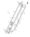
- Figure 1 shows a concealed door operator 1 according to a first exemplary embodiment of the present invention.
- the concealed door operator 1 comprises a housing 2, in which an operating unit 3 is provided.
- the operating unit 3 is adapted to operate a door equipped with the concealed door operator 1.
- the concealed door operator 1 can be provided within a cavity of a door leaf.
- the operating unit 3 For operating the door, i.e. for opening or closing the door, the operating unit 3 comprises a square pinion 4, which is the only part of the operating unit 3 being accessible from outside the housing 2.
- the square pinion 4 can be connected to a level arm which is supported on a wall.
- the square pinion 4 When opening or closing the door, the square pinion 4 is rotated and a load is applied to the operating unit 3.
- This energy is stored within the operating unit 3 and can be used for operating the door.
- energy is stored within the operating unit 3 when opening the door such that the concealed door closer 1 can use the stored energy for closing the door.
- the housing 2 of the concealed door operator 1 comprises a top face 6, an opposing bottom face 7 and side faces 8.
- mounting features 5 are provided on the top face 6, mounting features 5 are provided.
- the mounting features 5 comprise flanges 10 and through holes 11 for mounting the concealed door operator 1 on a door leaf or a wall or a floor.
- the concealed door operator 1 is installed within a cavity of the door leaf, while the flanges 10 of the mounting features 5 are disposed on surfaces outside the cavity. Mounting screws can be used for fixing the flanges 10 via the through holes 11 of the mounting features 5.
- the housing 2 is preferably a single cast piece, which can be made from aluminum or iron.
- the housing 2 is very simple to manufacture. Since the mounting features 5 are integrally formed with the housing 2, only a single cast piece has to be manufactured.
- the housing 2 according to the first exemplary embodiment has a generally prismatic shape.
- the mounting features 5, in particular the flanges 10, are provided on base faces 12 of the prism. This results in a narrow mounting space required for installation of the concealed door operator 1.
- the concealed door operator 1 has an operating unit 3 according to a non-handed version. That means the square pinion can be rotated clockwise or counter-clockwise to apply load to the operating unit 3. In particular, load is provided to an operating piston 13.
- the operating piston 13 is connected to a spring 18 which is adapted to store energy.
- the square pinion 4 is connected to a pinion cam 15 which is engaged with the operating piston. A rotation of the square pinion 4 and the pinion cam 15 therefore causes a longitudinal movement of the driving piston 13.
- the pinion cam 15 is engaged with a damping piston 14.
- the damping piston 14 functions to damp a movement of the pinion cam 15 and the operating piston 13. It is obvious that load is provided to the operating piston 13 independent from the rotating direction of the square pinion 4 and the pinion cam 15. Therefore, only one version of the concealed door operator 1 needs to be provided for realizing door operations in any direction.
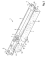
- Figure 2 shows a concealed door operator 1 according to a second exemplary embodiment of the present invention.
- the concealed door operator 1 according to the second exemplary embodiment is the same as in the first exemplary embodiment with the only difference being the operating unit 3.
- the operating unit 3 according to the second exemplary embodiment of the concealed door operator 1 comprises a driving piston 13 and a damping piston 14.
- the driving piston 13 is connected to the damping piston 14 via a rack 16.
- Engaged with the rack 16 is a pinion 17 which is connected to the square pinion 4.
- the operating piston 13 is connected to a spring 18 which is adapted to store energy.
- load can be applied to the operating unit 3 of the concealed door operator 1 of the second exemplary embodiment by rotating the square pinion 4.
- the rotation of the square pinion 4 results in a rotation of the pinion 16 and in a longitudinal movement of the rack 16. Since the rack 16 is connected to the driving piston 13, energy is stored within the spring 18. Additionally, any movement of the rack 16 is damped by the damping piston 14.
- the square pinion 4 can only be rotated in one direction for applying load to the spring 18.
- the square pinion has to be rotated clockwise for compressing the spring 18, i.e. for storing energy within the spring. Therefore, the concealed door operator 1 has to be provided in two different versions, in the one version load is applied to the operating unit 3 by rotation the square pinion 4 clockwise, and in another version load is applied to the operating unit 3 by rotation of the square pinion 4 counterclockwise. Nevertheless, this issue only regards the operating unit 3.
- the housing 2 and the remaining components of the concealed door operator 1 remain equal.
- the housing 2 comprises a cavity, which is provided on the top face 6 and which is covered by a cover plate (not shown).
- the cover plate can be made from metal such as aluminum or from plastics.
- the concealed door operator 1 provides several advantages in saving material during the manufacturing process of the concealed door operator 1. Therefore, the concealed door operator 1 is simple to manufacture and low in cost.
Landscapes
- Power-Operated Mechanisms For Wings (AREA)
- Closing And Opening Devices For Wings, And Checks For Wings (AREA)
Priority Applications (3)
| Application Number | Priority Date | Filing Date | Title |
|---|---|---|---|
| EP14003055.2A EP2993294A1 (de) | 2014-09-04 | 2014-09-04 | Verborgener Türbetätiger |
| CN201420700345.3U CN204457234U (zh) | 2014-09-04 | 2014-11-17 | 隐蔽的门控制器 |
| CN201410667840.3A CN105625850A (zh) | 2014-09-04 | 2014-11-17 | 隐蔽的门控制器 |
Applications Claiming Priority (1)
| Application Number | Priority Date | Filing Date | Title |
|---|---|---|---|
| EP14003055.2A EP2993294A1 (de) | 2014-09-04 | 2014-09-04 | Verborgener Türbetätiger |
Publications (1)
| Publication Number | Publication Date |
|---|---|
| EP2993294A1 true EP2993294A1 (de) | 2016-03-09 |
Family
ID=51690174
Family Applications (1)
| Application Number | Title | Priority Date | Filing Date |
|---|---|---|---|
| EP14003055.2A Withdrawn EP2993294A1 (de) | 2014-09-04 | 2014-09-04 | Verborgener Türbetätiger |
Country Status (2)
| Country | Link |
|---|---|
| EP (1) | EP2993294A1 (de) |
| CN (2) | CN204457234U (de) |
Citations (4)
| Publication number | Priority date | Publication date | Assignee | Title |
|---|---|---|---|---|
| US799342A (en) * | 1904-08-06 | 1905-09-12 | Yale & Towne Mfg Co | Combined floor-hinge, door check and closer. |
| EP1431497A2 (de) * | 2002-12-19 | 2004-06-23 | GEZE GmbH | Freilaufvorrichtung für den Antrieb eines Flügels einer Tür oder eines Fensters |
| EP2345788A2 (de) * | 2010-01-19 | 2011-07-20 | Taiwan Daedalus Door Control, Co., Ltd. | Türschließersatz für Pendeltür |
| EP2682552A2 (de) * | 2012-07-06 | 2014-01-08 | Leado Door Controls Ltd. | In Türplatte eingelassenes Bodenscharnier |
-
2014
- 2014-09-04 EP EP14003055.2A patent/EP2993294A1/de not_active Withdrawn
- 2014-11-17 CN CN201420700345.3U patent/CN204457234U/zh active Active
- 2014-11-17 CN CN201410667840.3A patent/CN105625850A/zh active Pending
Patent Citations (4)
| Publication number | Priority date | Publication date | Assignee | Title |
|---|---|---|---|---|
| US799342A (en) * | 1904-08-06 | 1905-09-12 | Yale & Towne Mfg Co | Combined floor-hinge, door check and closer. |
| EP1431497A2 (de) * | 2002-12-19 | 2004-06-23 | GEZE GmbH | Freilaufvorrichtung für den Antrieb eines Flügels einer Tür oder eines Fensters |
| EP2345788A2 (de) * | 2010-01-19 | 2011-07-20 | Taiwan Daedalus Door Control, Co., Ltd. | Türschließersatz für Pendeltür |
| EP2682552A2 (de) * | 2012-07-06 | 2014-01-08 | Leado Door Controls Ltd. | In Türplatte eingelassenes Bodenscharnier |
Also Published As
| Publication number | Publication date |
|---|---|
| CN105625850A (zh) | 2016-06-01 |
| CN204457234U (zh) | 2015-07-08 |
Similar Documents
| Publication | Publication Date | Title |
|---|---|---|
| CA2560394C (en) | Damping device for furniture hinges | |
| KR20140027271A (ko) | 가구 몸체의 측벽 상에 있는 붙박이 냉장고를 위한 체결 조립체 | |
| CN101142370B (zh) | 无框的玻璃门 | |
| EP2682552B1 (de) | In Türplatte eingelassenes Bodenscharnier | |
| US10526825B2 (en) | Cabinet assembly | |
| US9109388B2 (en) | Door coordinator accessory mounting bracket | |
| MX2015003598A (es) | Cerradura de puerta de vehiculo automotor. | |
| EP2993294A1 (de) | Verborgener Türbetätiger | |
| US7165793B2 (en) | Door jamb security plate | |
| JP6491854B2 (ja) | 引戸用施錠装置 | |
| EP2993293A1 (de) | Verborgener Türbetätiger | |
| EP2993292A1 (de) | Verborgener Türbetätiger | |
| EP1713992B1 (de) | Anordnung zur befestigung einer schaltsteuerwelle an einer schaltrohrwelle | |
| US5095583A (en) | Folding-arm bearing for an oscillating-swinging leaf | |
| EP2993295A1 (de) | Verborgener Türbetätiger | |
| EP3153800B1 (de) | Kühlschrank | |
| JP4299097B2 (ja) | ゲーム機の施錠装置 | |
| KR20090074930A (ko) | 도어용 하부힌지 구조 | |
| CN217999302U (zh) | 一种门轴结构、门框组件和门 | |
| KR20180000145U (ko) | 도어록킹장치 | |
| EP3037756A1 (de) | Haushaltsgerät zur kühlung von lebensmitteln | |
| KR20180001189U (ko) | 도어록킹장치 | |
| EP2937500A1 (de) | Zapfen für eine Tür | |
| JP2008111283A (ja) | チェック装置及びロータリポンプ | |
| GB2335699A (en) | Twin-hooked lock |
Legal Events
| Date | Code | Title | Description |
|---|---|---|---|
| PUAI | Public reference made under article 153(3) epc to a published international application that has entered the european phase |
Free format text: ORIGINAL CODE: 0009012 |
|
| AK | Designated contracting states |
Kind code of ref document: A1 Designated state(s): AL AT BE BG CH CY CZ DE DK EE ES FI FR GB GR HR HU IE IS IT LI LT LU LV MC MK MT NL NO PL PT RO RS SE SI SK SM TR |
|
| AX | Request for extension of the european patent |
Extension state: BA ME |
|
| 17P | Request for examination filed |
Effective date: 20160909 |
|
| RBV | Designated contracting states (corrected) |
Designated state(s): AL AT BE BG CH CY CZ DE DK EE ES FI FR GB GR HR HU IE IS IT LI LT LU LV MC MK MT NL NO PL PT RO RS SE SI SK SM TR |
|
| STAA | Information on the status of an ep patent application or granted ep patent |
Free format text: STATUS: REQUEST FOR EXAMINATION WAS MADE |
|
| STAA | Information on the status of an ep patent application or granted ep patent |
Free format text: STATUS: THE APPLICATION IS DEEMED TO BE WITHDRAWN |
|
| 18D | Application deemed to be withdrawn |
Effective date: 20160910 |