EP2992625B1 - Channel set allocation in frequency multiplexed communication in dense wireless environments - Google Patents
Channel set allocation in frequency multiplexed communication in dense wireless environments Download PDFInfo
- Publication number
- EP2992625B1 EP2992625B1 EP14726870.0A EP14726870A EP2992625B1 EP 2992625 B1 EP2992625 B1 EP 2992625B1 EP 14726870 A EP14726870 A EP 14726870A EP 2992625 B1 EP2992625 B1 EP 2992625B1
- Authority
- EP
- European Patent Office
- Prior art keywords
- wireless
- subset
- devices
- wireless devices
- stas
- Prior art date
- Legal status (The legal status is an assumption and is not a legal conclusion. Google has not performed a legal analysis and makes no representation as to the accuracy of the status listed.)
- Active
Links
- 238000004891 communication Methods 0.000 title claims description 171
- 230000005540 biological transmission Effects 0.000 claims description 142
- 238000000034 method Methods 0.000 claims description 85
- 238000004590 computer program Methods 0.000 claims description 6
- 208000001088 cerebrotendinous xanthomatosis Diseases 0.000 description 82
- 238000002512 chemotherapy Methods 0.000 description 82
- 230000007246 mechanism Effects 0.000 description 21
- 238000010586 diagram Methods 0.000 description 15
- 230000006870 function Effects 0.000 description 11
- 238000012545 processing Methods 0.000 description 10
- 238000013475 authorization Methods 0.000 description 9
- 230000004044 response Effects 0.000 description 9
- 238000005516 engineering process Methods 0.000 description 7
- 238000001228 spectrum Methods 0.000 description 6
- 239000000945 filler Substances 0.000 description 5
- 230000009471 action Effects 0.000 description 4
- 230000008901 benefit Effects 0.000 description 4
- 239000000835 fiber Substances 0.000 description 4
- 230000003287 optical effect Effects 0.000 description 4
- 230000036961 partial effect Effects 0.000 description 4
- 230000002441 reversible effect Effects 0.000 description 4
- 230000001360 synchronised effect Effects 0.000 description 4
- 230000006399 behavior Effects 0.000 description 3
- 230000008859 change Effects 0.000 description 3
- 230000000977 initiatory effect Effects 0.000 description 3
- 230000008569 process Effects 0.000 description 3
- 239000000523 sample Substances 0.000 description 3
- 230000009286 beneficial effect Effects 0.000 description 2
- 230000001413 cellular effect Effects 0.000 description 2
- 230000006855 networking Effects 0.000 description 2
- 230000002829 reductive effect Effects 0.000 description 2
- 238000012546 transfer Methods 0.000 description 2
- 108700026140 MAC combination Proteins 0.000 description 1
- 238000013459 approach Methods 0.000 description 1
- 238000004364 calculation method Methods 0.000 description 1
- 238000012512 characterization method Methods 0.000 description 1
- 239000003795 chemical substances by application Substances 0.000 description 1
- 230000008878 coupling Effects 0.000 description 1
- 238000010168 coupling process Methods 0.000 description 1
- 238000005859 coupling reaction Methods 0.000 description 1
- 230000001419 dependent effect Effects 0.000 description 1
- 230000002452 interceptive effect Effects 0.000 description 1
- 239000005022 packaging material Substances 0.000 description 1
- 230000000737 periodic effect Effects 0.000 description 1
- 230000011664 signaling Effects 0.000 description 1
- 230000003595 spectral effect Effects 0.000 description 1
- 230000003068 static effect Effects 0.000 description 1
- 238000010408 sweeping Methods 0.000 description 1
- 230000007704 transition Effects 0.000 description 1
Images


Classifications
-
- H—ELECTRICITY
- H04—ELECTRIC COMMUNICATION TECHNIQUE
- H04L—TRANSMISSION OF DIGITAL INFORMATION, e.g. TELEGRAPHIC COMMUNICATION
- H04L5/00—Arrangements affording multiple use of the transmission path
- H04L5/003—Arrangements for allocating sub-channels of the transmission path
- H04L5/0058—Allocation criteria
- H04L5/0073—Allocation arrangements that take into account other cell interferences
-
- H—ELECTRICITY
- H04—ELECTRIC COMMUNICATION TECHNIQUE
- H04B—TRANSMISSION
- H04B7/00—Radio transmission systems, i.e. using radiation field
- H04B7/24—Radio transmission systems, i.e. using radiation field for communication between two or more posts
- H04B7/26—Radio transmission systems, i.e. using radiation field for communication between two or more posts at least one of which is mobile
- H04B7/2621—Radio transmission systems, i.e. using radiation field for communication between two or more posts at least one of which is mobile using frequency division multiple access [FDMA]
-
- H—ELECTRICITY
- H04—ELECTRIC COMMUNICATION TECHNIQUE
- H04B—TRANSMISSION
- H04B7/00—Radio transmission systems, i.e. using radiation field
- H04B7/24—Radio transmission systems, i.e. using radiation field for communication between two or more posts
- H04B7/26—Radio transmission systems, i.e. using radiation field for communication between two or more posts at least one of which is mobile
-
- H—ELECTRICITY
- H04—ELECTRIC COMMUNICATION TECHNIQUE
- H04J—MULTIPLEX COMMUNICATION
- H04J1/00—Frequency-division multiplex systems
- H04J1/02—Details
-
- H—ELECTRICITY
- H04—ELECTRIC COMMUNICATION TECHNIQUE
- H04J—MULTIPLEX COMMUNICATION
- H04J1/00—Frequency-division multiplex systems
- H04J1/02—Details
- H04J1/14—Arrangements providing for calling or supervisory signals
-
- H—ELECTRICITY
- H04—ELECTRIC COMMUNICATION TECHNIQUE
- H04L—TRANSMISSION OF DIGITAL INFORMATION, e.g. TELEGRAPHIC COMMUNICATION
- H04L1/00—Arrangements for detecting or preventing errors in the information received
- H04L1/12—Arrangements for detecting or preventing errors in the information received by using return channel
- H04L1/16—Arrangements for detecting or preventing errors in the information received by using return channel in which the return channel carries supervisory signals, e.g. repetition request signals
- H04L1/1607—Details of the supervisory signal
- H04L1/1685—Details of the supervisory signal the supervisory signal being transmitted in response to a specific request, e.g. to a polling signal
-
- H—ELECTRICITY
- H04—ELECTRIC COMMUNICATION TECHNIQUE
- H04L—TRANSMISSION OF DIGITAL INFORMATION, e.g. TELEGRAPHIC COMMUNICATION
- H04L1/00—Arrangements for detecting or preventing errors in the information received
- H04L1/12—Arrangements for detecting or preventing errors in the information received by using return channel
- H04L1/16—Arrangements for detecting or preventing errors in the information received by using return channel in which the return channel carries supervisory signals, e.g. repetition request signals
- H04L1/18—Automatic repetition systems, e.g. Van Duuren systems
-
- H—ELECTRICITY
- H04—ELECTRIC COMMUNICATION TECHNIQUE
- H04L—TRANSMISSION OF DIGITAL INFORMATION, e.g. TELEGRAPHIC COMMUNICATION
- H04L5/00—Arrangements affording multiple use of the transmission path
- H04L5/0001—Arrangements for dividing the transmission path
- H04L5/0003—Two-dimensional division
- H04L5/0005—Time-frequency
-
- H—ELECTRICITY
- H04—ELECTRIC COMMUNICATION TECHNIQUE
- H04L—TRANSMISSION OF DIGITAL INFORMATION, e.g. TELEGRAPHIC COMMUNICATION
- H04L5/00—Arrangements affording multiple use of the transmission path
- H04L5/003—Arrangements for allocating sub-channels of the transmission path
- H04L5/0037—Inter-user or inter-terminal allocation
-
- H—ELECTRICITY
- H04—ELECTRIC COMMUNICATION TECHNIQUE
- H04L—TRANSMISSION OF DIGITAL INFORMATION, e.g. TELEGRAPHIC COMMUNICATION
- H04L5/00—Arrangements affording multiple use of the transmission path
- H04L5/003—Arrangements for allocating sub-channels of the transmission path
- H04L5/0048—Allocation of pilot signals, i.e. of signals known to the receiver
- H04L5/005—Allocation of pilot signals, i.e. of signals known to the receiver of common pilots, i.e. pilots destined for multiple users or terminals
-
- H—ELECTRICITY
- H04—ELECTRIC COMMUNICATION TECHNIQUE
- H04L—TRANSMISSION OF DIGITAL INFORMATION, e.g. TELEGRAPHIC COMMUNICATION
- H04L5/00—Arrangements affording multiple use of the transmission path
- H04L5/003—Arrangements for allocating sub-channels of the transmission path
- H04L5/0053—Allocation of signaling, i.e. of overhead other than pilot signals
- H04L5/0055—Physical resource allocation for ACK/NACK
-
- H—ELECTRICITY
- H04—ELECTRIC COMMUNICATION TECHNIQUE
- H04L—TRANSMISSION OF DIGITAL INFORMATION, e.g. TELEGRAPHIC COMMUNICATION
- H04L5/00—Arrangements affording multiple use of the transmission path
- H04L5/0091—Signaling for the administration of the divided path
- H04L5/0094—Indication of how sub-channels of the path are allocated
-
- H—ELECTRICITY
- H04—ELECTRIC COMMUNICATION TECHNIQUE
- H04W—WIRELESS COMMUNICATION NETWORKS
- H04W52/00—Power management, e.g. TPC [Transmission Power Control], power saving or power classes
- H04W52/02—Power saving arrangements
- H04W52/0209—Power saving arrangements in terminal devices
- H04W52/0212—Power saving arrangements in terminal devices managed by the network, e.g. network or access point is master and terminal is slave
- H04W52/0219—Power saving arrangements in terminal devices managed by the network, e.g. network or access point is master and terminal is slave where the power saving management affects multiple terminals
-
- H—ELECTRICITY
- H04—ELECTRIC COMMUNICATION TECHNIQUE
- H04W—WIRELESS COMMUNICATION NETWORKS
- H04W74/00—Wireless channel access, e.g. scheduled or random access
- H04W74/02—Hybrid access techniques
-
- H—ELECTRICITY
- H04—ELECTRIC COMMUNICATION TECHNIQUE
- H04L—TRANSMISSION OF DIGITAL INFORMATION, e.g. TELEGRAPHIC COMMUNICATION
- H04L1/00—Arrangements for detecting or preventing errors in the information received
- H04L1/12—Arrangements for detecting or preventing errors in the information received by using return channel
- H04L1/16—Arrangements for detecting or preventing errors in the information received by using return channel in which the return channel carries supervisory signals, e.g. repetition request signals
- H04L1/18—Automatic repetition systems, e.g. Van Duuren systems
- H04L1/1829—Arrangements specially adapted for the receiver end
- H04L1/1861—Physical mapping arrangements
-
- H—ELECTRICITY
- H04—ELECTRIC COMMUNICATION TECHNIQUE
- H04L—TRANSMISSION OF DIGITAL INFORMATION, e.g. TELEGRAPHIC COMMUNICATION
- H04L1/00—Arrangements for detecting or preventing errors in the information received
- H04L2001/0092—Error control systems characterised by the topology of the transmission link
- H04L2001/0093—Point-to-multipoint
-
- H—ELECTRICITY
- H04—ELECTRIC COMMUNICATION TECHNIQUE
- H04L—TRANSMISSION OF DIGITAL INFORMATION, e.g. TELEGRAPHIC COMMUNICATION
- H04L5/00—Arrangements affording multiple use of the transmission path
-
- H—ELECTRICITY
- H04—ELECTRIC COMMUNICATION TECHNIQUE
- H04L—TRANSMISSION OF DIGITAL INFORMATION, e.g. TELEGRAPHIC COMMUNICATION
- H04L5/00—Arrangements affording multiple use of the transmission path
- H04L5/0001—Arrangements for dividing the transmission path
- H04L5/0003—Two-dimensional division
- H04L5/0005—Time-frequency
- H04L5/0007—Time-frequency the frequencies being orthogonal, e.g. OFDM(A), DMT
- H04L5/0012—Hopping in multicarrier systems
-
- H—ELECTRICITY
- H04—ELECTRIC COMMUNICATION TECHNIQUE
- H04L—TRANSMISSION OF DIGITAL INFORMATION, e.g. TELEGRAPHIC COMMUNICATION
- H04L5/00—Arrangements affording multiple use of the transmission path
- H04L5/003—Arrangements for allocating sub-channels of the transmission path
- H04L5/0058—Allocation criteria
- H04L5/006—Quality of the received signal, e.g. BER, SNR, water filling
-
- H—ELECTRICITY
- H04—ELECTRIC COMMUNICATION TECHNIQUE
- H04L—TRANSMISSION OF DIGITAL INFORMATION, e.g. TELEGRAPHIC COMMUNICATION
- H04L5/00—Arrangements affording multiple use of the transmission path
- H04L5/003—Arrangements for allocating sub-channels of the transmission path
- H04L5/0058—Allocation criteria
- H04L5/0069—Allocation based on distance or geographical location
-
- H—ELECTRICITY
- H04—ELECTRIC COMMUNICATION TECHNIQUE
- H04W—WIRELESS COMMUNICATION NETWORKS
- H04W74/00—Wireless channel access, e.g. scheduled or random access
- H04W74/002—Transmission of channel access control information
-
- H—ELECTRICITY
- H04—ELECTRIC COMMUNICATION TECHNIQUE
- H04W—WIRELESS COMMUNICATION NETWORKS
- H04W74/00—Wireless channel access, e.g. scheduled or random access
- H04W74/08—Non-scheduled or contention based access, e.g. random access, ALOHA, CSMA [Carrier Sense Multiple Access]
- H04W74/0808—Non-scheduled or contention based access, e.g. random access, ALOHA, CSMA [Carrier Sense Multiple Access] using carrier sensing, e.g. as in CSMA
- H04W74/0816—Non-scheduled or contention based access, e.g. random access, ALOHA, CSMA [Carrier Sense Multiple Access] using carrier sensing, e.g. as in CSMA carrier sensing with collision avoidance
-
- Y—GENERAL TAGGING OF NEW TECHNOLOGICAL DEVELOPMENTS; GENERAL TAGGING OF CROSS-SECTIONAL TECHNOLOGIES SPANNING OVER SEVERAL SECTIONS OF THE IPC; TECHNICAL SUBJECTS COVERED BY FORMER USPC CROSS-REFERENCE ART COLLECTIONS [XRACs] AND DIGESTS
- Y02—TECHNOLOGIES OR APPLICATIONS FOR MITIGATION OR ADAPTATION AGAINST CLIMATE CHANGE
- Y02D—CLIMATE CHANGE MITIGATION TECHNOLOGIES IN INFORMATION AND COMMUNICATION TECHNOLOGIES [ICT], I.E. INFORMATION AND COMMUNICATION TECHNOLOGIES AIMING AT THE REDUCTION OF THEIR OWN ENERGY USE
- Y02D30/00—Reducing energy consumption in communication networks
- Y02D30/70—Reducing energy consumption in communication networks in wireless communication networks
Definitions
- the present application relates generally to wireless communications, and more specifically to systems, methods, and devices for frequency multiplexed wireless communication in dense wireless environments.
- communications networks are used to exchange messages among several interacting spatially-separated devices.
- Networks can be classified according to geographic scope, which could be, for example, a metropolitan area, a local area, or a personal area. Such networks would be designated respectively as a wide area network (WAN), metropolitan area network (MAN), local area network (LAN), wireless local area network (WLAN), or personal area network (PAN).
- WAN wide area network
- MAN metropolitan area network
- LAN local area network
- WLAN wireless local area network
- PAN personal area network
- Networks also differ according to the switching/routing technique used to interconnect the various network nodes and devices (for example, circuit switching vs. packet switching), the type of physical media employed for transmission (for example, wired vs. wireless), and the set of communication protocols used (for example, Internet protocol suite, SONET (Synchronous Optical Networking), Ethernet, etc.).
- Wireless networks are often preferred when the network elements are mobile and thus have dynamic connectivity needs, or if the network architecture is formed in an ad hoc, rather than fixed, topology.
- Wireless networks employ intangible physical media in an unguided propagation mode using electromagnetic waves in the radio, microwave, infra-red, optical, etc. frequency bands. Wireless networks advantageously facilitate user mobility and rapid field deployment when compared to fixed wired networks.
- multiple wireless networks may exist in the same building, in nearby buildings, and/or in the same outdoor area.
- the prevalence of multiple wireless networks may cause interference, reduced throughput (for example, because each wireless network is operating in the same area and/or spectrum), and/or prevent certain devices from communicating.
- EP 1 592 178 A2 describes a high-throughput (HT) wireless LAN system capable of avoiding a collision of packets and maintaining the original transmission speed.
- a transmitter is applied to an HT terminal (HTAP) using a second frequency band wider than a first frequency band used by a legacy terminal (legacy AP), in which an HT sequence is started after a legacy beacon as an occupation signal and a legacy CTS are transmitted using every frequency in the second frequency band. Due to this, an NAV is set at the legacy terminal and packets are no longer transmitted from the legacy terminal. As a result, a collision of packets is avoided and it becomes possible to perform communication between HT terminals at the original transmission speed.
- HTAP HT terminal
- legacy AP legacy terminal
- US 2012/0026997 A1 discloses a method and apparatus of accessing a channel in a wireless local area network.
- the method includes receiving, by a device, an operation element for setting up or switching at least one channel from an access point (AP), the operation element including a channel type field indicating whether the at least one channel is either a single channel or multiple channels, and the operation element including two channel center frequency segment fields indicating channel center frequency of a primary channel and a secondary channel respectively if the channel type field indicates that the at least one channel is multiple channels, determining whether the primary channel is idle during a first interval, determining whether the secondary channel is idle during a second interval if the primary channel is idle, and transmitting data by using the primary channel and the secondary channel to the AP or at least one station in a basic ser-vice set (BSS) if the primary channel and the secondary channel are idle.
- BSS basic ser-vice set
- the present invention provides a solution according to the subject matter of the independent claims.
- WLAN wireless local area networks
- a WLAN can be used to interconnect nearby devices together, employing widely used networking protocols.
- the various aspects described herein may apply to any communication standard, such as a wireless protocol.
- wireless signals can be transmitted according to a high-efficiency 802.11 protocol using orthogonal frequency-division multiplexing (OFDM), direct-sequence spread spectrum (DSSS) communications, a combination of OFDM and DSSS communications, or other schemes.
- OFDM orthogonal frequency-division multiplexing
- DSSS direct-sequence spread spectrum
- Implementations of the high-efficiency 802.11 protocol can be used for Internet access, sensors, metering, smart grid networks, or other wireless applications.
- aspects of certain devices implementing the high-efficiency 802.11 protocol using the techniques disclosed herein may include allowing for increased peer-to-peer services (for example, Miracast, WiFi Direct Services, Social WiFi, etc.) in the same area, supporting increased per-user minimum throughput requirements, supporting more users, providing improved outdoor coverage and robustness, and/or consuming less power than devices implementing other wireless protocols.
- peer-to-peer services for example, Miracast, WiFi Direct Services, Social WiFi, etc.
- a WLAN includes various devices which are the components that access the wireless network.
- access points access points
- STAs stations
- an AP may serve as a hub or base station for the WLAN and an STA serves as a user of the WLAN.
- an STA can be a laptop computer, a personal digital assistant (PDA), a mobile phone, etc.
- PDA personal digital assistant
- an STA connects to an AP via a WiFi (for example, IEEE 802.11 protocol) compliant wireless link to obtain general connectivity to the Internet or to other wide area networks.
- WiFi for example, IEEE 802.11 protocol
- an STA may also be used as an AP.
- An access point may also comprise, be implemented as, or known as a NodeB, Radio Network Controller (“RNC”), eNodeB, Base Station Controller (“BSC”), Base Transceiver Station (“BTS”), Base Station (“BS”), Transceiver Function (“TF”), Radio Router, Radio Transceiver, or some other terminology.
- RNC Radio Network Controller
- BSC Base Station Controller
- BTS Base Transceiver Station
- BS Base Station
- Transceiver Function TF
- Radio Router Radio Transceiver, or some other terminology.
- a station “STA” may also comprise, be implemented as, or known as an access terminal ("AT”), a subscriber station, a subscriber unit, a mobile station, a remote station, a remote terminal, a user terminal, a user agent, a user device, user equipment, or some other terminology.
- an access terminal may comprise a cellular telephone, a cordless telephone, a Session Initiation Protocol ("SIP”) phone, a wireless local loop (“WLL”) station, a personal digital assistant (“PDA”), a handheld device having wireless connection capability, or some other suitable processing device connected to a wireless modem.
- SIP Session Initiation Protocol
- WLL wireless local loop
- PDA personal digital assistant
- a phone for example, a cellular phone or smartphone
- a computer for example, a laptop
- a portable communication device for example, a headset
- a portable computing device for example, a personal data assistant
- an entertainment device for example, a music or video device, or a satellite radio
- a gaming device or system for example, a global positioning system device, or any other suitable device that is configured to communicate via a wireless medium.
- certain of the devices described herein may implement a high-efficiency 802.11 standard, for example.
- Such devices whether used as an STA or AP or other device, can be used for smart metering or in a smart grid network.
- Such devices may provide sensor applications or be used in home automation.
- the devices may instead or in addition be used in a healthcare context, for example for personal healthcare. They may also be used for surveillance, to enable extended-range Internet connectivity (for example, for use with hotspots), or to implement machine-to-machine communications.
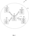
- FIG. 1 shows an exemplary wireless communication system 100 in which aspects of the present disclosure can be employed.
- the wireless communication system 100 may operate pursuant to a wireless standard, for example a high-efficiency 802.11 standard.
- the wireless communication system 100 may include an AP 104, which communicates with STAs 106.
- a variety of processes and methods can be used for transmissions in the wireless communication system 100 between the AP 104 and the STAs 106.
- signals can be sent and received between the AP 104 and the STAs 106 in accordance with OFDM/OFDMA techniques. If this is the case, the wireless communication system 100 can be referred to as an OFDM/OFDMA system.
- signals can be sent and received between the AP 104 and the STAs 106 in accordance with code division multiple access (CDMA) techniques. If this is the case, the wireless communication system 100 can be referred to as a CDMA system.
- CDMA code division multiple access
- a communication link that facilitates transmission from the AP 104 to one or more of the STAs 106 can be referred to as a downlink (DL) 108, and a communication link that facilitates transmission from one or more of the STAs 106 to the AP 104 can be referred to as an uplink (UL) 110.
- DL downlink
- UL uplink
- a downlink 108 can be referred to as a forward link or a forward channel
- an uplink 110 can be referred to as a reverse link or a reverse channel.
- the AP 104 may act as a base station and provide wireless communication coverage in a basic service area (BSA) 102.
- BSA basic service area
- the AP 104 along with the STAs 106 associated with the AP 104 and that use the AP 104 for communication can be referred to as a basic service set (BSS).
- BSS basic service set
- the wireless communication system 100 may not have a central AP 104, but rather may function as a peer-to-peer network between the STAs 106. Accordingly, the functions of the AP 104 described herein may alternatively be performed by one or more of the STAs 106.
- a STA 106 can be required to associate with the AP 104 in order to send communications to and/or receive communications from the AP 104.
- information for associating is included in a broadcast by the AP 104. To receive such a broadcast, the STA 106 may, for example, perform a broad coverage search over a coverage region. A search may also be performed by the STA 106 by sweeping a coverage region in a lighthouse fashion, for example. After receiving the information for associating, the STA 106 may transmit a reference signal, such as an association probe or request, to the AP 104.
- the AP 104 may use backhaul services, for example, to communicate with a larger network, such as the Internet or a public switched telephone network (PSTN).
- PSTN public switched telephone network
- the AP 104 includes an AP high-efficiency wireless component (HEWC) 154.
- the AP HEWC 154 may perform some or all of the operations described herein to enable communications between the AP 104 and the STAs 106 using the high-efficiency 802.11 protocol.
- the functionality of some implementations of the AP HEWC 154 is described in greater detail below with respect to FIGS. 2B , 3 , 4 , and 8 .
- the STAs 106 may include a STA HEWC 156.
- the STA HEWC 156 may perform some or all of the operations described herein to enable communications between the STAs 106 and the AP 104 using the highfrequency 802.11 protocol.
- the functionality of some implementations of the STA HEWC 156 is described in greater detail below with respect to FIGS. 2B , 3 , 4 , 8B, and 10B.
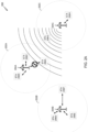
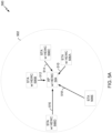
- FIG. 2A shows a wireless communication system 200 in which multiple wireless communication networks are present.
- BSAs 202A, 202B, and 202C can be physically located near each other.
- the APs 204A-204C and/or STAs 206A-206H may each communicate using the same spectrum.
- devices outside the BSA 202C for example, APs 204A-204B or STAs 206A-206F may sense the communication on the medium.
- wireless networks that use a regular 802.11 protocol (for example, 802.11a, 802.11b, 802.11g, 802.11n, etc.) operate under a carrier sense multiple access (CSMA) mechanism for medium access.
- CSMA carrier sense multiple access
- devices sense the medium and only transmit when the medium is sensed to be idle.
- the APs 204A-204C and/or STAs 206A-206H are operating according to the CSMA mechanism and a device in the BSA 202C (for example, the AP 204C) is transmitting data
- the APs 204A-204B and/or STAs 206A-206F outside of the BSA 202C may not transmit over the medium even though they are part of a different BSA.
- FIG. 2A illustrates such a situation.
- AP 204C is transmitting over the medium.
- the transmission is sensed by STA 206G, which is in the same BSA 202C as the AP 204C, and by STA 206A, which is in a different BSA than the AP 204C. While the transmission can be addressed to the STA 206G and/or only STAs in the BSA 202C, STA 206A nonetheless may not be able to transmit or receive communications (for example, to or from the AP 204A) until the AP 204C (and any other device) is no longer transmitting on the medium.
- STAs 206D-206F in the BSA 202B and/or STAs 206B-206C in the BSA 202A may apply to STAs 206D-206F in the BSA 202B and/or STAs 206B-206C in the BSA 202A as well (for example, if the transmission by the AP 204C is stronger such that the other STAs can sense the transmission on the medium).
- each apartment unit may include an access point and associated stations.
- each apartment unit may include multiple access points, as a resident may own a wireless router, a video game console with wireless media center capabilities, a television with wireless media center capabilities, a cell phone that can act like a personal hot-spot, and/or the like. Correcting the inefficiencies of the CSMA mechanism may then be vital to avoid latency and throughput issues and overall user dissatisfaction.
- Such latency and throughput issues may not be confined to residential areas.
- multiple access points can be located in airports, subway stations, and/or other densely-populated public spaces.
- WiFi access can be offered in these public spaces, but for a fee. If the inefficiencies created by the CSMA mechanism are not corrected, then operators of the wireless networks may lose customers as the fees and lower quality of service begin to outweigh any benefits.
- the high-efficiency 802.11 protocol described herein may allow for devices to operate under a modified mechanism that minimizes these inefficiencies and increases network throughput. Such a mechanism is described below with respect to FIGS. 2B , 3 , and 4 . Additional aspects of the high-efficiency 802.11 protocol are described below with respect to FIGS. 5 -13.
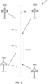
- FIG. 2B shows a wireless communication system 250 in which multiple wireless communication networks are present.
- the wireless communication system 250 may operate pursuant to the high-efficiency 802.11 standard discussed herein.
- the wireless communication system 250 may include an AP 254A, an AP 254B, and an AP 254C.
- the AP 254A may communicate with STAs 256A-256C
- the AP 254B may communicate with STAs 256D-256F
- the AP 254C may communicate with STAs 256G-256H.
- a variety of processes and methods can be used for transmissions in the wireless communication system 250 between the APs 254A-254C and the STAs 256A-256H.
- signals can be sent and received between the APs 254A-254C and the STAs 256A-256H in accordance with OFDM/OFDMA techniques or CDMA techniques.
- the AP 254A may act as a base station and provide wireless communication coverage in a BSA 252A.
- the AP 254B may act as a base station and provide wireless communication coverage in a BSA 252B.
- the AP 254C may act as a base station and provide wireless communication coverage in a BSA 252C. It should be noted that each BSA 252A, 252B, and/or 252C may not have a central AP 254A, 254B, or 254C, but rather may allow for peer-to-peer communications between one or more of the STAs 256A-256H. Accordingly, the functions of the AP 254A-254C described herein may alternatively be performed by one or more of the STAs 256A-256H.
- the APs 254A-254C and/or STAs 256A-256H include a high-efficiency wireless component.
- the high-efficiency wireless component may enable communications between the APs and STAs using the high-efficiency 802.11 protocol.
- the high-efficiency wireless component may enable the APs 254A-254C and/or STAs 256A-256H to use a modified mechanism that minimizes the inefficiencies of the CSMA mechanism (for example, enables concurrent communications over the medium in situations in which interference would not occur).
- the high-efficiency wireless component is described in greater detail below with respect to FIG. 4 .
- the BSAs 252A-252C are physically located near each other.
- the communication can be sensed by other devices in BSAs 252B-252C.
- the communication may only interfere with certain devices, such as STA 256F and/or STA 256G.
- AP 254B would not be allowed to communicate with STA 256E even though such communication would not interfere with the communication between AP 254A and STA 256B.
- the high-efficiency 802.11 protocol operates under a modified mechanism that differentiates between devices that can communicate concurrently and devices that cannot communicate concurrently.
- "concurrently" can mean at least partially overlapping in time.
- Such classification of devices can be performed by the high-efficiency wireless component in the APs 254A-254C and/or the STAs 256A-256H.
- the determination of whether a device can communicate concurrently with other devices is based on a "location" of the device.
- a STA that is located near an "edge" of the BSA can be in a state or condition such that the STA cannot communicate concurrently with other devices.
- STAs 206A, 206F, and 206G can be devices that are in a state or condition in which they cannot communicate concurrently with other devices.
- a STA that is located near the center of the BSA can be in a station or condition such that the STA can communicate concurrently with other devices. As illustrated in FIG.
- STAs 206B, 206C, 206D, 206E, and 206H can be devices that are in a state or condition in which they can communicate concurrently with other devices. Note that the classification of devices is not permanent. Devices may transition between being in a state or condition such that they can communicate concurrently and being in a state or condition such that they cannot communicate concurrently (for example, devices may change states or conditions when in motion, when associating with a new AP, when disassociating, etc.).
- a device can be classified as an "edge” device based on a physical location, a radio “location” (for example, a radio frequency characteristic), or a combination thereof.
- the STA 256B can be physically close to the AP 254A.
- the STA 256B can be classified as an inner-cell device (i.e., not an "edge” device) based on its physical proximity to the AP 254A.
- the STA 256B can be likely to successfully communicate with the AP 254A, even while the STA 256G is concurrently transmitting.
- the STA 256C can be physically close to the AP 254A, but its antenna might be oriented poorly for communication with the AP 254A. For example, it's the STA 256C could have a directional antenna pointed at the STA 256G. Accordingly, although the STA 256C might be physically close to the AP 254A, it can be classified as an edge device due to poor RF characteristics with respect to the AP 254A. In other words, the STA 256C might be unlikely to successfully communicate with the AP 254A while the STA 256G is concurrently transmitting.
- the STA 256A might be physically close to the AP 254A, but it might also be physically close to the STA 256G. Due to the proximity between the STA 256A and the STA 256G, the STA 256A might be unlikely to successfully communicate with the AP 254A while the STA 256G is concurrently transmitting. In this embodiment, the STA 256A might also be characterized as an edge device.
- RF characteristics that affect the characterization of a STA as an inner-cell device or a cell-edge device can include one or more of: a signal-to-interference-plus-noise ratio (SINR), an RF geometry, a received signal strength indicator (RSSI), a modulation and coding scheme (MCS) value, an interference level, a signal level, etc.
- SINR signal-to-interference-plus-noise ratio
- RSSI received signal strength indicator
- MCS modulation and coding scheme
- one or more physical and RF characteristics can be compared to one or more threshold levels. The comparisons can be weighted and/or combined.
- devices can be determined to be in a condition such that they can or cannot communicate concurrently based on the solitary, weighted, and/or combined physical and RF characteristics and associated thresholds.
- Devices can be configured to behave differently based on whether they are ones that are or are not in a state or condition to communicate concurrently with other devices. For example, devices that are in a state or condition such that they can communicate concurrently (which can be referred to herein as “inner cell” devices) may communicate within the same spectrum. However, devices that are in a state or condition such that they cannot communicate concurrently (which can be referred to herein as "cell-edge” devices) may employ certain techniques, such as spatial multiplexing or frequency domain multiplexing, in order to communicate over the medium.
- the controlling of the behavior of the devices can be performed by the high-efficiency wireless component in the APs 254A-254C and/or the STAs 256A-256H.
- STAs 256A, 256C, and 256G can be cell-edge devices, while STAs 256B and 256H can be inner-cell devices.
- the STAs 256A and 256C may form a first subset of cell-edge devices configured to communicate with the AP 254A on a first sub-channel (or set of sub-channels).
- the first subset of cell-edge devices can be associated with a first BSA 252A.
- the STA 256G may form a second subset of cell-edge devices configured to communicate with the AP 254C on a second sub-channel (or set of sub-channels), which can be orthogonal to the first sub-channel.
- the second subset of cell-edge devices can be associated with a second BSA 252C.
- the STA 256A can communicate at the same time (but on a different sub-channel) as the STA 256G.
- the STA 256B may communicate with the AP 254A using a third sub-channel and the STA 256H can communicate with the AP 254C using the third sub-channel.
- the STA 256B can communicate at the same time (and on at least some overlapping channels) as the STA 256H. Because the STAs 256B and 256H are inner-cell devices, they are unlikely to interfere with each other. In various embodiments, the STAs 256B and 256H can also communicate on different overlapping or non-overlapping sub-channels.
- one or more devices in each BSA can coordinate frequency use and re-use so as to reduce or minimize the chances of interference.
- one or more devices in the first BSA 252A can transmit an instruction to one or more devices in the first and/or second BSAs 252A and/or 252C, identifying sub-channels for use by cell-edge devices in one or both BSAs 252A and 252C.
- the AP 254A can instruct the STA 256A to use a specific sub-channel, and can subsequently instruct the STA 256A to use another sub-channel.
- the AP 254A can instruct the STA 256G to use a specific sub-channel, and can subsequently instruct the STA 256G to use another sub-channel.
- cell-edge devices in the first BSA 252A can simply start using a first sub-channel (or set of sub-channels). For example, the cell-edge devices in the first BSA 252A can choose a first sub-channel based on one or more RF characteristics such as the sub-channel or set of sub-channels with the least interference.
- the cell-edge devices in the second BSA 252C can observe the use of the first sub-channel and can choose a second sub-channel (or set of sub-channels). For example, new interference on the first sub-channel may cause the cell-edge devices in the second BSA 252C to choose the second sub-channel.
- frequency use and re-use can be uncoordinated.
- the cell-edge devices can be configured to hop between sub-channels on a scheduled, random, or pseudo-random basis.
- the STA 256A can use a specific sub-channel for a first period of time, and can subsequently use another sub-channel.
- the STA 256G can use a specific sub-channel for a first period of time, and can subsequently use another sub-channel.
- the STAs 256A and 256G might hop to the same sub-channel by chance. However, they are also likely to occasionally transmit on different channels.
- FIG. 3 shows frequency multiplexing techniques that can be employed within the wireless communication systems 100 of FIG. 1 and 250 of FIG. 2B .
- an AP 304A, 304B, 304C, and 304D can be present within a wireless communication system 300.
- Each of the APs 304A, 304B, 304C, and 304D can be associated with a different BSA and include the high-efficiency wireless component described herein.
- the 80 MHz available bandwidth is divided into four 20MHz segments 308, 310, 312, and 314 (for example, channels).
- the AP 304A can be associated with segment 308, the AP 304B can be associated with segment 310, the AP 304C can be associated with segment 312, and the AP 304D can be associated with segment 314.
- other size sub-channels can be used.
- sub-channels can be between about 1 MHz and 40 MHZ, between about 2 MHz and 10 MHz, and more particularly about 5 MHz.
- sub-channels can be contiguous or non-contiguous (for example, interleaved).
- each AP 304A-304D and each of these STAs may communicate using a portion of or the entire 80MHz medium.
- APs and/or STAs even those that are in a state or condition such that they cannot communicate concurrently with other devices, that include the high-efficiency wireless component, can communicate concurrently with other APs and STAs without interference. Accordingly, the throughput of the wireless communication system 300 can be increased. In the case of apartment buildings or densely-populated public spaces, APs and/or STAs that use the high-efficiency wireless component may experience reduced latency and increased network throughput even as the number of active wireless devices increases, thereby improving user experience.
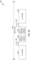
- FIG. 4 shows an exemplary functional block diagram of a wireless device 402 that can be employed within the wireless communication systems 100, 250, and/or 300 of FIGS. 1 , 2B , and 3 .
- the wireless device 402 is an example of a device that can be configured to implement the various methods described herein.
- the wireless device 402 may comprise the AP 104, one of the STAs 106, one of the APs 254, one of the STAs 256, and/or one of the APs 304.
- the wireless device 402 may include a processor 404 which controls operation of the wireless device 402.
- the processor 404 may also be referred to as a central processing unit (CPU).
- Memory 406 which may include both read-only memory (ROM) and random access memory (RAM), may provide instructions and data to the processor 404.
- a portion of the memory 406 may also include non-volatile random access memory (NVRAM).
- the processor 404 typically performs logical and arithmetic operations based on program instructions stored within the memory 406.
- the instructions in the memory 406 can be executable to implement the methods described herein.
- the processor 404 may comprise or be a component of a processing system implemented with one or more processors.
- the one or more processors can be implemented with any combination of general-purpose microprocessors, microcontrollers, digital signal processors (DSPs), field programmable gate array (FPGAs), programmable logic devices (PLDs), controllers, state machines, gated logic, discrete hardware components, dedicated hardware finite state machines, or any other suitable entities that can perform calculations or other manipulations of information.
- the processing system may also include machine-readable media for storing software.
- Software shall be construed broadly to mean any type of instructions, whether referred to as software, firmware, middleware, microcode, hardware description language, or otherwise. Instructions may include code (for example, in source code format, binary code format, executable code format, or any other suitable format of code). The instructions, when executed by the one or more processors, cause the processing system to perform the various functions described herein.
- the wireless device 402 may also include a housing 408 that may include a transmitter 410 and/or a receiver 412 to allow transmission and reception of data between the wireless device 402 and a remote location.
- the transmitter 410 and receiver 412 can be combined into a transceiver 414.
- An antenna 416 can be attached to the housing 408 and electrically coupled to the transceiver 414.
- the wireless device 402 may also include (not shown) multiple transmitters, multiple receivers, multiple transceivers, and/or multiple antennas.
- the wireless device 402 may also include a signal detector 418 that can be used in an effort to detect and quantify the level of signals received by the transceiver 414.
- the signal detector 418 may detect such signals as total energy, energy per subcarrier per symbol, power spectral density and other signals.
- the wireless device 402 may also include a digital signal processor (DSP) 420 for use in processing signals.
- DSP digital signal processor
- the DSP 420 can be configured to generate a packet for transmission.
- the packet may comprise a physical layer data unit (PPDU).
- PPDU physical layer data unit
- the wireless device 402 may further comprise a user interface 422 in some aspects.
- the user interface 422 may comprise a keypad, a microphone, a speaker, and/or a display.
- the user interface 422 may include any element or component that conveys information to a user of the wireless device 402 and/or receives input from the user.
- the wireless devices 402 may further comprise a high-efficiency wireless component 424 in some aspects.
- the high-efficiency wireless component 424 may include a classifier unit 428 and a transmit control unit 430. As described herein, the high-efficiency wireless component 424 may enable APs and/or STAs to use a modified mechanism that minimizes the inefficiencies of the CSMA mechanism (for example, enables concurrent communications over the medium in situations in which interference would not occur).
- the various components of the wireless device 402 can be coupled together by a bus system 426.
- the bus system 426 may include a data bus, for example, as well as a power bus, a control signal bus, and a status signal bus in addition to the data bus.
- a data bus for example, as well as a power bus, a control signal bus, and a status signal bus in addition to the data bus.
- Those of skill in the art will appreciate the components of the wireless device 402 can be coupled together or accept or provide inputs to each other using some other mechanism.
- the wireless device 402 may comprise an AP 104, a STA 106, an AP 254, a STA 256, and/or an AP 304, and can be used to transmit and/or receive communications. That is, either the AP 104, STA 106, AP 254, STA 256, or AP 304 may serve as transmitter or receiver devices. Certain aspects contemplate signal detector 418 being used by software running on memory 406 and processor 404 to detect the presence of a transmitter or receiver.
- FIG. 5A shows the wireless communication system 500 in which aspects of the present disclosure can be employed.
- the wireless communication system 500 includes a BSA 502.
- the BSA 502 may include the AP 504 and STAs 506A-506E.
- the AP 504 and the STAs 506A-506D each include the high-efficiency wireless component discussed above.
- the STA 506E does not include the high-efficiency wireless component.
- STAs 506A-506D are referred to as high-efficiency STAs
- STA 506E is referred to as a legacy STA (for example, because it is compatible with regular IEEE 802.11 protocols, such as IEEE 802.11n, IEEE 802.11ac, etc.).
- the legacy STA 506E would reserve an entire available bandwidth (for example, 80 MHz) while transmitting to a legacy AP (which does not include the high-efficiency wireless component) via a legacy channel (for example, 20 MHz).
- the high-efficiency AP 504 can be configured to receive data on multiple sub-channels simultaneously.
- the STA 506A can transmit to the AP 504 via uplink (UL) communication 510
- the STA 506B can transmit to the AP 504 via uplink (UL) communication 512
- the STA 506C can transmit to the AP 504 via uplink (UL) communication 514 at the same time as the STA 506E transmits to the AP 504 via uplink (UL) communication 518.
- the UL communication 518 can be a legacy channel communication, and the UL communications 510, 512, and 514 can be high-efficiency channel communications occupying unused available sub-channels.
- the STA 506D can also transmit to the AP 504 via UL communication 516.
- STAs 506A-506C can be located closer to the AP 504 than STAs 506D-506E.
- the UL communications 510, 512, 514, 516, and 518 can be made by the AP 504 according to the uplink frequency domain multiplexing (UL FDM) protocol described herein.
- UL FDM uplink frequency domain multiplexing
- An UL FDM protocol may include three data exchange stages: (1) data transmission; (2) protection; and (3) acknowledgment.
- the protection stage may precede the data transmission stage and the acknowledgment stage may follow the data transmission stage.
- techniques can be employed to prevent interference.
- data one or more STAs may transmit data to the AP.
- the acknowledgment stage the STAs may confirm that the AP received the appropriate data.
- Each of these stages may occur concurrently on different channels according to the frequency domain multiplexing principles discussed herein.
- the UL FDM protocol may include rules related to the timing of the start of transmissions by the STAs 306A-306E ( FIG. 3 ).
- data is transmitted simultaneously by multiple STAs on different channels.
- the STAs can transmit on any channel discussed herein, particularly those within the available bandwidth.
- several data transmission options are available during the data transmission stage.
- several options are available for allocating STAs on different channels such that the STAs can communicate concurrently. These options may also allow for both legacy STAs and high-efficiency STAs to communicate concurrently.
- the techniques described herein to improve network throughput and reduce latency can be implemented in devices that are compatible with high-efficiency STAs and that are backwards compatible with existing legacy STAs.
- an existing PHY layer of the regular IEEE 802.11 protocol (for example, the 802.11n, 802.11ac, etc.) can be coupled with a new media access control (MAC) mechanism to allocate STAs on different channels.
- MAC media access control
- a new PHY layer preamble can be created for the high-efficiency 802.11 protocol and be used by STAs on different channels.
- the existing PHY layer of the regular IEEE 802.11 protocol and the new PHY layer preamble can be used by STAs to transmit STAs on different channels simultaneously or essentially simultaneously.
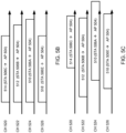
- FIGS. 5B-5C show a timing diagram in which aspects of the present disclosure can be employed.
- FIGS. 5B-5C show a timing diagram that can be used in accordance with the existing PHY layer of the regular IEEE 802.11 protocol and the new MAC mechanism.
- four channels are present: channel 520, channel 522, channel 524, and channel 526.
- the term channel used herein can refer to any of a contiguous portion of spectrum or a set of non-adjacent intervals of spectrum, in which case the term bandwidth for the channel can refer to the sum of the bandwidth of each interval.
- the channels 520, 522, 524, and 526 can be contiguous (for example, each channel 520, 522, 524, and 526 covers consecutive 20MHz frequency ranges, such as from 1000MHz to 1080MHz) or non-contiguous (for example, there are gaps in frequency between one or more of the channels 520, 522, 524, and/or 526).
- all transmissions come from HEW STAs.
- one transmission comes from a legacy STA, and one or more other transmissions come from one or more HEW STAs.
- the transmission bandwidth of each STA can be same or can be different.
- exemplary bandwidths used by each STA can include one or more of 2.5 MHz, 5 MHz, 7.5 MHz, 10 MHz, 15 MHz, 20 MHz, 30 MHz, 40 MHz, 60 MHz, and 80MHz.
- transmissions from all the STAs can be allocated such that no transmissions are on adjacent channels.
- the primary channel (alone or in combination with additional secondary channels, for example in legacy 11n/11ac operation) is used for communications from legacy STAs (for example, STA 506E) to the AP 504.
- Secondary channels are also used for communications from high-efficiency STAs (for example, STAs 506A-506D) to the AP 504.
- duration of the transmission from multiple STAs can be same or different. Different amounts of data and different data rate used for the transmission can result in a different time for the transmission of each data. In certain cases, it is advantageous that all the transmissions end at the same time, irrespective of the different minimum times that would be used by each STA to send the data. In such cases where all the transmissions end at the same time, each STA can include one or more additional padding bytes to the frame, so that the frame length matches a target frame length.
- the target duration can be indicated in a frame received immediately before the transmission (for example, the reference signals CTX described below with respect to FIGS. 6A-6C ), and/or can be previously negotiated or indicated by the AP.
- the padding operation can be performed by adding one or more aggregated media access control protocol data unit (A-MPDU) sub-frames and/or padding bytes, for example as defined in the IEEE 802.11ac standard.
- A-MPDU aggregated media access control protocol data unit
- the AP 504 transmits, and the STAs 506A-506E receive, a MAC message that associates the STAs 506A-506E with channels, thereby indicating which channel the AP 504 plans to use to communicate or receive a communication with a respective STA 506A-506E.
- the AP 504 defaults to communicating with the STA 506E on the primary channel since the STA 506E is a legacy STA.
- the STA 506E can default to the primary channel for transmissions to the AP 504.
- the AP 504 may not transmit the MAC message to the STA 506E.
- the AP 504 may transmit the MAC message only to the high-efficiency STAs 506A-506D.
- the AP 504 transmits the MAC message to each STA 506A-506E.
- the MAC message can include one or more management frames sent from the AP 504 to the STAs 506A-506D, and can include an indication of the allocated channel for each STA (either explicitly or implicitly such as based on a categorization).
- the MAC message is referred to as a reference signal, described in greater detail below with respect to FIG. 7A .
- transmission can be synchronized based on a solicited or unsolicited reference signal from the AP 504. In other embodiments, transmission can be synchronized based on a schedule set by the AP 504 and/or STAs 506A-506E.
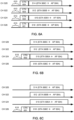
- FIGS. 6A-6C show another timing diagram in which aspects of the present disclosure can be employed.
- the primary channel for example, channel 526) and/or one or more of the secondary channels (for example, channels 520, 522, and/or 524) can be used for transmissions by legacy STAs and the primary channel and/or secondary channels can be used for transmissions by high-efficiency STAs.
- the channels 520, 522, 524, and/or 526 may or may not be contiguous.
- the AP 504 can transmit one or more unsolicited reference signals CTX 601-604 to the STAs 506A-506E.
- the reference signals CTX 601-604 can indicate that STAs with data to send should begin transmitting upon receipt (or at a predetermined synchronization point after receipt).
- the synchronization point can be at, for example, a short inter-frame space (SIFS), a point coordination function (PCF) inter-frame space (PIFS), or another predefined time after the end of reception of the CTX frame.
- the STAs 506A-506E receive the reference signal CTX 601-604 can begin to transmit the communications 510, 512, 514, and 518.
- the reference signals CTX 601-604 are described in greater detail herein with respect to FIG. 7A .
- the synchronization point can be referred to as a time of joint transmission.
- the AP 504 can transmit the reference signal CTX 601-602 on a plurality of sub-channels, or even all sub-channels.
- the STAs 506A-506E are only able to receive on their assigned channel. Accordingly, the AP 504 transmits the reference signal CTX 601-604 on all channels.
- each CTXs can contain same information. In some embodiments, various CTXs can contain different information on each channel.
- the STAs 506A-506E can receive the reference signal on any channel. Accordingly, as shown in FIG. 6B , the AP 504 may transmit a single reference signal CTX 602 on any sub-channel that can be received by the STAs 506A-506E, for example, on the primary channel.
- the legacy STA 506E can only receive the reference signal CTX 601 on the primary channel 526.
- the HEW STAs 506A-506C are able to receive the reference signal CTX 601 on any channel. Accordingly, the AP 504 transmits the reference signal CTX 601 on the primary channel 526.
- other combinations of STA capability are possible.
- the AP 504 can be configured to transmit the reference signals CTX 601-604 on a minimum number of sub-channels in order to notify all target STAs. 506A-506E.
- the AP 504 may transmit a reference signal CTX 601 on the sub-channel with the least interference, or may transmit one or more redundant reference signals CTX 601-604.
- the reference signals CTX 601-604 sent on multiple sub-channels can be exactly same, or can be different per sub-channel.
- a random back-off counter can be associated with a CTX transmission channel (such as the primary channel 526 in FIG. 6C ), as defined by the enhanced distributed channel access (EDCA) procedure of IEEE 802.11.
- the AP 504 can begin preparing one or more reference signals CTX 601-604 for transmission to the STAs 506A-506E. If the intended CTX transmission channel has been idle since a time period 610 before the time that the random back-off counter expired, then the AP 504 may transmit the one or more reference signals CTX 601-604. Thus, once the random back-off counter expires, at least one transmission is made over the primary channel.
- the time period 610 can be based on a PIFS time. The PIFS time can be chosen by the AP 504 and/or STAs 506A-506E.
- FIGS. 6D-6F show another timing diagram in which aspects of the present disclosure can be employed.
- the primary channel for example, channel 526) and/or one or more of the secondary channels (for example, channels 520, 522, and/or 524) can be used for transmissions by legacy STAs and the secondary channels can be used for transmissions by high-efficiency STAs.
- the channels 520, 522, 524, and/or 526 may or may not be contiguous.
- one or more STAs 506A-506E can request the reference signals CTX 601-604 by transmitting a request-to-send (RTX) 620.
- RTX request-to-send
- an RTX can be compatible with legacy hardware.
- the RTX can include an RTS as defined in IEEE 802.11, or can include another frame.
- the AP 504 can transmit one or more solicited reference signals CTX 601-604 to the STAs 506A-506E.
- the reference signals CTX 601-604 can indicate that STAs with data to send should being transmitting upon receipt (or at a predetermined synchronization point after receipt).
- the STAs 506A-506E receive the reference signal CTX 601-604 can begin to transmit the communications 510, 512, 514, and 518.
- CTX messages can identify which STAs are allowed to transmit and on which channels.
- the AP 504 can transmit the reference signal CTX 601-602 over a plurality of sub-channels, or even all sub-channels.
- the STAs 506A-506E are only able to receive on their assigned channel. Accordingly, the AP 504 transmits the reference signal CTX 601-604 on all channels.
- the STAs 506A-506E can be able to receive the reference signal on any channel. Accordingly, as shown in FIG. 6E , the AP 504 may transmit a single reference signal CTX 602 on any sub-channel that can be received by the STAs 506A-506E.
- the AP 504 may transmit a single reference signal CTX 602 on a different channel as the RTX 620. As shown in FIG. 6F , the AP 504 may transmit a single reference signal CTX 602 on the same channel as the RTX 620.
- the AP 504 can be configured to transmit the reference signals CTX 601-604 on a minimum number of sub-channels in order to notify all target STAs. 506A-506E. In some embodiments, where more than one sub-channel will suffice, the AP 504 may transmit a reference signal CTX 601 on the sub-channel with the least interference, or may transmit one or more redundant reference signals CTX 601-604.
- any STAs 506A-506E with data to send can transmit the RTX 620, which can be compatible with legacy hardware such as the STA 506E.
- a STA transmits the RTX 620 on the same channel on which it will transmit data.
- the HEW STAs 506A-506E can transmit the RTX 620 on any available channel, a channel with the least interference, a first available channel according the EDCA, etc.
- the STAs 506A-506E can transmit the RTX according to EDCA, as discussed above with respect to the CTX 601-604.
- a random back-off counter can be associated with a RTX transmission channel (such as the primary channel 526 in FIG. 6F ), as defined by the enhanced distributed channel access (EDCA) procedure of IEEE 802.11.
- EDCA enhanced distributed channel access
- the STA 506E can transmit an RTX frame 620 in a designated channel (for example, the primary channel) for transmission to the AP 504. If additional channels (for example, non-primary channels) RTX have been idle since a time period 610 (see FIG.
- the STA 506E may transmit the one or more RTX frames 620 on the primary and on the available secondary channels.
- the AP 504 can respond with a CTS or CTX frame in same set or subset of the channel where the RTX is received, and can send a CTX in one or more additional channels not within the channels where the RTX was received.
- the channels where the CTX is sent can include the channels where the medium was determined to be idle.
- the medium can be determined to be idle by checking the channel for a PIFS time before the RTX reception or for a SIFS time after the RTX reception.
- the time period 610 can be based on a PIFS time. The PIFS time can be chosen by the AP 504 and/or STAs 506A-506E.
- the CTX can include information granting transmission to the STA 506E on the channels where the RTX was sent and can include information granting transmission to other STAs on the channels where the RTX was not sent. In another embodiment, the CTX can include information granting transmission for the STA 506 on a subset of the RTX channels and may grant transmission to other STAs on the channels where the RTX was not sent.
- RTX frames can be an RTX in a legacy format and can be sent by a legacy STAs (such as the STA 506E), hence allowing a legacy STA to initiate an UL transmit procedure.
- the AP 504 can respond with a CTX having a format compatible with the format of a legacy CTS, thus enabling consistent operation at the STA.
- the AP 504 can detect whether an RTX was received from a legacy or high efficiency STA by, for example, comparing a transmit address with a stored lookup table.
- the AP 504 can detect whether an RTX was received from a legacy or high efficiency STA by reading an explicit indication embedded in the legacy RTX format.
- the RTX can include a control frame including one or more of the following fields: a frame control, a duration, a source address, a destination address, and an information payload.
- the information payload can include one or more of the following indications: a requested transmission time, a size of a transmission queue, a quality-of-service (QoS) indication for the requested transmission, and a requested transmission bandwidth.
- the QoS indication can include, for example, a traffic identifier (TID), a transport stream identifier (TSID), and/or any other QoS Class).
- the RTX control frame can omit one or more fields discussed above and/or include one or more fields not discussed above, including any of the fields discussed herein.
- the fields in the RTX control frame discussed above can be of different suitable lengths, and can be in a different order.
- HTC high throughput control
- RDG indication reverse decision grant
- such a frame according to IEEE 802.11 can signal that a portion transmit opportunity indicated by the duration field and not used by the current transmission can be used by the recipient AP.
- the recipient AP can use the transmit opportunity to initiate an uplink (UL) frequency division multiple access (FDMA) transmission in any of the modes described herein.
- UL uplink
- FDMA frequency division multiple access
- the AP 504 and/or the STAs 506A-506E can determine a scheduled time at which the STAs 506A-506E should begin transmitting.
- scheduling mechanisms can be used to define a time that the AP 504 should expect packets from the STAs 506A-506E.
- One scheduling mechanism can be based on a reference time agreed between the AP and each individual STA via a management exchange.
- the reference time can be periodic, intermittent, or randomly or pseudo randomly determined. Selection of the reference time can be achieved with a protocol such as a target wakeup time (TWT) timing, which is defined in the IEEE 802.11ah protocol.
- TWT target wakeup time
- the AP can define the same reference time for multiple STAs by setting the TWT to same value for multiple STAs.
- the TWT timing can be a time during which a STA is scheduled to be awake.
- another scheduling mechanism can be based on defining a reference time for a group of STAs and an associated interval of time where access is restricted to the group of STAs. For example, such scheduling can be achieved with a restricted access window (RAW) timing, which is defined in the IEEE 802.11ah protocol.
- RAW timing can be an interval of time during which access to a medium is restricted to a group of STAs.
- the interval of time can further be slotted and each slot assigned to one or more STAs, indicating that STAs can transmit UL data at the start of the slot time.
- STAs can be ready to receive a CTX frame for initiating the transmission.
- STAs may start transmission without waiting for the CTX.
- STAs can be transmitting at exactly the reference time, or it can perform a clear channel assessment procedure on the intended transmission channel, starting at the reference time.
- the channel assessment may require a PIFS time or DIFS time. If the target channel is determined to be busy, the STA can refrain from transmitting.
- the STAs can be operating in HCCA mode, during a Contention Free period.
- STAs are not allowed to access the medium until a CF-Poll message is received (802.11); the HCCA protocol can be modified such that the CF-Poll message identifies more than one STAs for UL transmission at SIFS time after the CF-Poll frame.
- the CF-Poll can be replaced with any of the CTX frames described herein.
- the AP 504 may further include in management messages used to set up the scheduled time (for example, an RPS information element for RAW, TWT setup messages for TWT, etc.) an indication of the channel allocation for the benefit of the STAs.
- management messages used to set up the scheduled time for example, an RPS information element for RAW, TWT setup messages for TWT, etc.
- the allocation indicated by the AP 504 in such a message can be in response to a message transmitted by a STA to the AP 504 requesting the use of a specific channel or simply the allocation of a channel.
- the message can be included in a management frame.
- the transmissions from the STAs 506A-506E may start at the time scheduled according to the TWT timing or the RAW timing.
- the random back-off counter, the PIFS timing, and/or the AIFS timing can be used as described herein to determine whether the channel has been idle for an appropriate amount of time.
- a benefit of scheduling a transmission time based on the TWT timing or the RAW timing can be that the AP 504 then knows when the STAs 506A-506E will be awake.
- the STAs 506A-506E may not use the random back-off counter, the PIFS timing, and/or the AIFS timing.
- the STAs 506A-506E may not use the PIFS timing and/or the AIFS timing on secondary channels.
- the AP 504 can transmit the reference signal CTX 601-604 at the scheduled time.
- the AP 504 can use the same scheduling mechanism as the STAs 506A-506E (for example, TWT timing or RAW timing) to determine when to transmit the reference signal CTX 601-604.
- the AP 504 can transmit the reference signal CTX 601-604 after sensing the medium as idle on the intended CTX channel.
- the AP 504 can transmit the reference signal CTX as described above with respect to the RTX 620.
- the reference signals CTX 601-604 can include a clear-to-send frame, an extended clear-to-send frame, and/or an aggregated MAC protocol data unit (MPDU) including a clear-to-send frame and a new frame including an extended payload.
- reference signals can be referred to as MAC messages.
- one or more reference signals CTX 601-604 can include the same format (or compatible) as a legacy CTS as defined in 802.11.
- reference signals CTX 601-604 include a multicast MAC address, for example, in a receiver address (RA) field of the CTS.
- the reference signals CTX 601-604 can have same format (compatible format) as a CF-Poll frame as defined in 802.11 or a Synch frame as defined in 802.11ah. Poll frames can include a multicast receiver address.
- the reference signals CTX 601-604 can include one or more of the following indications: a deferral time for third party STAs, one or more identifiers of STAs that are eligible to transmit via UL-FDMA at one certain (for example, a short inter-frame space (SIFS), a point coordination function (PCF) inter-frame space (PIFS), or longer) time after the reference signal frame, indications of a power at which each of the STAs 506A-506E should transmit (for example, an indication of the backoff with respect to a reference power), an indication, for each STA, of the channel(s) and/or bandwidth the STAs 506A-506E should use to transmit, channel assignments for one or more STAs, a time synchronization indication, an ACK policy indication for one or more STAs, an exact or maximum duration of the data transmission, a number of spatial streams or number of space-time streams for each STA, an indication of the length of all the information fields included in the CTX, a
- the identifier of STAs that are eligible to transmit can include a list of addresses (for example, MAC addressed, AIDs, partial or hashed AIDs, etc.) and/or one or more group identifiers.
- the group identifier can include, for example, a multicast MAC address previously associated to a group of STAs and communicated to the STAs, or a group identifier previously defined and communicated to the STAs.
- the transmit power indicator can include, for example, an absolute power indicator or an indication of a back-off from a STA nominal transmit power, which the STAs 506A-506E can indicate.
- one or more of the aforementioned payload elements can be negotiated or predetermined between each STA 506A-506E and the AP 504.
- the payload elements can be included in an extended payload, or distributed in other fields.
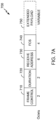
- FIG. 7A shows an example reference signal 700 that can be employed within the wireless communication systems of FIGS. 1 , 2B , and 3 .
- the reference signal 700 includes a frame control field 710, a duration field 720, a receive address field 730, a frame check sequence (FCS) 740, and an extended payload 750.
- the frame control field 710 is two bytes long
- the duration field 720 is two bytes long
- the receive address 720 is six bytes long
- the FCS 740 is four bytes long
- the extended payload 750 is a variable length.
- the reference signal 700 can omit one or more fields shown in FIG. 7A and/or include one or more fields not shown in FIG.
- the reference signal 700 can be of different suitable lengths, and can be in a different order.
- the extended payload 750 can be omitted.
- the reference signal 700 is a clear-to-send frame.
- the extended payload 750 can include one or more of the payload elements or indications discussed above.
- the extended payload can include a an identifier of STAs that are eligible to transmit via UL-FDMA at a time after the reference signal frame, an indication of a power at which the STAs 506A-506E should transmit, an indication of the channel(s) and/or bandwidth the STAs 506A-506E should use to transmit, specific channel assignments, and/or a synchronization indication.
- the time after the reference signal frame can include a SIFS, a PIFS, or a time longer than PIFS.
- the time can be indicated by the AP 504 ( FIG. 5A ) in the reference signal 700, or communicated by the AP 504 to STAs in a previous message, or defined by the standard. The AP 504 can define the time based on indications received from STAs
- the reference signal 700 can include an indication that the reference signal 700 includes an extended CTS frame including the extended payload 750.
- the reference signal 700 can set one or more bits normally reserved in control frames to indicate the presence of the extended payload 750. Accordingly, a legacy STA 506E can be able to interpret at least some fields of the CTS frame.
- the CTX frame can include one or more padding bytes inserted after the information bytes.
- the purpose of the padding byte can be to increase the length of the CTX, so as to provide additional time for the processing of the CTX information from the recipient STAs.
- the padding bytes can be identified as following the information bytes, according to the length of the information bytes indicated in one of the CTX fields.
- the reference signal 700 can omit the extended payload 750 and/or include a control wrapper frame indicating the presence of a high-throughput control (HTC) field.
- the HTC field may provide four bytes that can be used to embed identifiers of target STAs information.
- a special CTS message may include additional information after the FCS field.
- the CTX message can include a CTS message with an HT Control field (for example, as defined in IEEE 802.11).
- the presence of the HT Control (HTC) field in the CTS can be identified, for example as defined in the IEEE 802.11 standard.
- the HTC field can be overridden to carry one or more of the indications listed above.
- the fact that the HTC is overridden to signal the above information can be indicated by one or more of the type of PHY preamble used for the transmission, and one or more bits in the HTC control field itself.
- RDG reverse decision grant
- this may act as the trigger indication for the UL FDMA transmissions.
- the HTC field can be overridden to carry the necessary information, as described above.
- the CTX frame can be the same or similar to a power save multi-poll (PSMP) frame (for example, as defined by the 802.11 standard), wherein the PSMP-UTT start offset within a STA info field identifies the start time for the UL FDMA transmissions, the PSMP UTT duration identifies the duration of the UL FDMA transmission and the STA ID field may include an identifier of the STAs allowed to transmit.
- the reserved bits can be used to indicate a power backoff, a transmission bandwidth (BW), and/or a channel allocation.
- Multiple STA info fields can be included in a same PSMP frame, with a same value of start offset and duration, hence indicating that multiple STAs can transmit in UL FDMA at the indicated time.
- FIG. 7B shows exemplary reference signal formats and fields that can be employed within the wireless communication systems of FIGS. 1 , 2B , and 3 .
- the reference signal is the same or similar to a PSMP frame, as discussed above.
- the reference signal of FIG. 7B can omit one or more fields shown in FIG. 7B and/or include one or more fields not shown in FIG. 7B , including any of the fields discussed herein.
- the fields in the reference signal of FIG. 7B can be of different suitable lengths, and can be in a different order.
- a PSMP parameter set fixed field can include a five-bit number of STAs field N_STA, a six-bit More PSMP field, and a 10-bit PSMP Sequence Duration field.
- a PSMP STA Info fixed field when group addressed, can include a two-bit STA_INFO Type field (set to "1"), an 11-bit PSMP-DTT Start Offset field, an 8-bit PSMP-DTT Duration field, and a 43-bit PSMP Group Address ID.
- the PSMP STA Info fixed field when individually addressed, can include a two-bit STA_INFO Type field (set to "2"), an 11-bit PSMP-DTT Start Offset field, an 8-bit PSMP-DTT Duration field, a 16-bit STA_ID field, an 11-bit PSMP-UTT Start Offset field, a 10-bit PSMP-UTT Duration field, and six reserved bits.
- a PSMP frame Action field can include a category field, an HT Action field, a PSMP Parameter Set, and one or more PSMP STA Info fields repeated N_STA times.
- a new value of the STA info type can be used to indicate that the STA info field includes the start offset field, the duration field, and a field identifying the multiple STAs allowed to transmit (for example, as a group identifier, a list of addresses or partial addresses, etc.).
- the group of destination STAs can be identified by the receive address (RA) of the frame itself.
- the reference signal can otherwise include the rest of the PSMP frame format.
- the use of the PSMP frame allows indicating multiple UL and DL schedules for UL and DL transmissions.
- FIG. 7C shows an example reference signal 760 that can be employed within the wireless communication systems of FIGS. 1 , 2B , and 3 .
- the reference signal 760 includes the frame control field 710, the duration field 720, the receive address field 730, a transmit address field 762, a length field 764, a STA info field 766, one or more optional padding bits 768, and the frame check sequence (FCS) 740.
- FCS frame check sequence
- the frame control field 710 is two bytes long
- the duration field 720 is two bytes long
- the receive address 720 is six bytes long
- the transmit address field 762 is six bytes long
- the length field 764 is one byte long
- the STA info field is a variable length N*X
- the padding bits 768 are a variable length M
- the FCS 740 is four bytes long.
- the reference signal 760 can omit one or more fields shown in FIG. 7C and/or include one or more fields not shown in FIG. 7C , including any of the fields discussed herein. A person having ordinary skill in the art will appreciate that the fields in the reference signal 760 can be of different suitable lengths, and can be in a different order.
- the receive address field 730, the length field 764, and/or the padding bits 768 can be omitted.
- the reference signal 760 is a clear-to-send frame.
- the RA 730 is present only in case it is used for identifying the group of recipient STAs.
- the length field 764 may include either a length N in bytes of the information portion 766, or a number X of STA info fields.
- the STA info field 766 can include one or more of the per-STA indications listed above. In various embodiments, it can have the same length for each STA.
- the padding bits 768 can include M byes of padding, to increase the frame length.
- the CTX message can be sent as a single frame with a transmission BW spanning the total transmission BW allocated for UL transmissions; it can be sent as a duplicate across all the channels allocated for UL transmissions, i.e., the content of each CTX is exactly the same across channels; and it can be different per-channel, carrying different information for different STAs receiving on different channels.
- CTSs sent on different channels with either different BW or different information can have a different length, which may be contrary to the purpose of providing a reference synchronization time to all the STA for the UL transmission.
- each CTX can include a number of padding bytes so that the length of all the CTXs is same.
- the CTX frame can be followed by an additional "filler" frame sent by the same sender of the CTX, after a SIFS time.
- the filler frame can serve to keep the medium busy and provide additional time to the STAs for the processing and interpretation of the CTX information and for the preparation of the following UL transmission.
- the filler frame can be any of an null data packet (NDP), CTS, or other control frame.
- NDP null data packet
- CTS CTS
- the filler frame can also provide additional protection for the upcoming transmissions.
- the need for, or inclusion of, padding and/or a filler frame can be indicated by a STA to the AP with an indication at association (for example, in an association request) or through a management exchange.
- the STA can also indicate the amount of time required for processing, which can determine the amount of padding required.
- the AP can schedule transmissions at a time where multiple STAs are awake and have available data, hence maximizing the efficiency.
- the AP may also indicate to the STAs that no transmission are allowed outside the scheduled periods. This indication can be included in the beacon or included in the setup phase (see “Setup,” below) for each STA.
- the AP 504 can indicate a list of STAs that are eligible to transmit, for example in the reference signal 700 ( FIG. 7A ) or during transmission scheduling.
- STAs 506A-506E can indicate that they have data to transmit in a QoS control field of any data packet sent by the STAs 506A-506E to the AP 504.
- the STAs 506A-506E can transmit a QoS null data frame to the AP 504, which can include the QoS control field, to indicate that the STA 506A-506E has buffered units for transmission.
- the STAs 506A-506E can transmit the QoS control field in any data frame using regular contention procedures.
- the AP 504 can receive the QoS control field, determine which STAs 506A-506E have data to transmit, and determine which STAs 506A-506E to indicate for transmission eligibility.
- the STAs 506A-506E can indicate that they have data to transmit by encoding an uplink data indication in a power-save poll (PS-Poll) frame according to 802.11ah.
- the STAs 506A-506E can indicate that they have data to transmit by transmitting another frame via regular CSMA contention.
- the AP 504 can indicate a window during which STAs 506A-506E should transmit indications that they have buffered units.
- the window of time can be advertised in a Beacon and be essentially similar to a RAW in some embodiments.
- the advertisement can be achieved, for example, by using an RPS information element as defined by the IEEE 802.11ah standard, with the following change: the type of the RAW is indicated to be for UL indication only.
- the AP can also schedule a TWT with each individual STA for allowing the STA to send an UL indication.
- FIG. 8 shows another timing diagram 850 in which aspects of the present disclosure can be employed.
- the AP 504 transmits channel allocation messages 802, 804, 806, and 808 on each of the channels 520, 522, 524, and 526, respectively.
- the channel allocation messages CHA 802, 804, 806, and 808 may provide information to the STAs 506A-506E regarding which channel is allocated to which STA.
- the channel allocation messages 802, 804, 806, and/or 808 can be the MAC message or reference signal 800 ( FIG. 8 ) described above.
- the PHY layer preamble 528 includes a group identification field that corresponds to a channel allocation of the STAs of the group.
- the channels can be pre-allocated, selected by the STAs 506A-506E, and/or selected by the AP 506A-506E and explicitly messaged via the channel allocation messages 802, 804, 806, and/or 808.
- the channel allocation messages 802, 804, 806, and/or 808 can be sent at any time prior to the transmission by each STA.
- the AP 504 can include channel allocation in the reference signals CTX 601-604 ( FIGS. 6A-6F ) or MAC frames 802, 804, 806, and/or 808 sent immediately before the data transmission 510, 512, 514, and/or 518.
- the channel allocation can be indicated by one or more MAC addresses, AIDs, partial or hashed AIDs, and corresponding channel identifiers.
- a group can be defined that includes multiple STAs, each STA can be assigned a position in the group, and the group can be identified by a group ID or by a multicast MAC address.
- a channel allocated to a STA can be identified by the group ID or multicast MAC address, and further by the position of the STA in the group identified by the group ID.
- Messages for setting up the group definitions can be sent at any time before the UL-FDMA data transmissions 510, 512, 514, and/or 518 and can be carried by management frames.
- Messages for indicating channel allocation for a certain data transmission can be conveyed by management or control frames sent before the data transmission 510, 512, 514, and/or 518 (for example, these frames may not be transmitted based on SIFS or PIFS as described above), or can be sent on a synchronization or MAC frame immediately preceding the data transmission 510, 512, 514, and/or 518.
- the receiver address can include a multicast MAC address corresponding to a group and hence identifying the channel for the STA.
- a random static allocation can be used (for example, each STA is allocated to a channel, semi-statically).
- the AP 504 may indicate to the STAs 506A-506E which station is allocated to which channel (for example, via the channel allocation messages 802, 804, 806, and/or 808). If the channels are selected by the STAs 506A-506E, STAs 506A-506E may select and wait on a channel preferred by the respective STA 506A-506E.
- the STAs 506A-506E may explicitly or implicitly (for example, via any transmission) notify the AP 504 of their presence on the respective channel.
- the channel allocation messages 802, 804, 806, and/or 808 can be sent on each of the channels or just a primary channel.
- the STAs 506A-506E implicitly notify the AP 504 of their presence, the AP 504 may know of a STA 506A-506E location based on reception of any data, control, and/or management frame transmitted by the STA 506A-506E for regular operation. In other words, the data, control, and/or management frame may not necessarily be designed for channel indication.
- the reception of a reference signal addressed to a STA on an certain channel can implicitly indicate that the certain channel is allocated to the addressed STA.
- the AP 504 can transmit multiple reference frames CTX on multiple channels, each addressed to a different STA, thereby defining the channel allocation.
- RTX and CTX messages are used by the AP 504 and the STAs 506A-506E to ensure that a given channel is free.
- the duration field in RTX and CTS can indicate a duration that covers the immediately following transmission, plus the required acknowledgments.
- restrictions can be placed on the duration of a packet.
- transmissions by the STAs 506A-506E have different lengths. In other embodiments, transmissions by the STAs 506A-506E have the same length.
- the AP 504 may respond with a block acknowledgment (BA) acknowledging that the DL communication was received.
- BA block acknowledgment
- the AP 504 may respond with the BA on its own volition or can be prompted to by the STAs 506A-506E (for example, via a block acknowledgment request (BAR)). If the STAs 506A-506E are all able to receive on any channel, or are all able to receive on at least a same common channel (such as the primary channel), the AP 504 may broadcast a single block acknowledgment (BBA).
- the BBA frame carries block acknowledgment indications for multiple STAs, possibly all the STAs that sent data in UL.
- the BBA can be sent on the primary channel.
- APs 504 and/or STAs 506A-506E can transmit BAs, BARs, and/or BBAs in a legacy or high-efficiency physical protocol data unit (PPDU) format.
- PPDU physical protocol data unit
- the bandwidth can be smaller than 20 MHz.
- different BAs, BARs, and/or BBAs can have different durations, which can depend on a bandwidth used for transmission. Timing diagrams included herein, and the various messages they show, are not to scale.
- FIGS. 9A-9C show additional timing diagrams in which aspects of the present disclosure can be employed.
- FIGS. 9A-9C illustrate the use of BAs, BARs, and BBAs as described herein.
- transmissions 51, 512, 514, and 518 do not end at the same time, the AP 504 responds immediately with a BA after the UL communication is complete. The AP 504 then responds to the remaining transmissions with a BA after receiving a BAR.
- the STAs 506A-506E may transmit the BAR on the channel that the UL communication was transmitted on, the primary channel, the high-efficiency primary channel (for example, a primary channel defined for use by the high-efficiency devices), and/or any other channel.
- the AP 504 may respond with a BA 904A after the UL communication 514 is complete.
- the STA 506C may transmit a BAR 902B to the AP 504 on the channel 522, which is the channel that the DL communication 512 was received by the STA 506B.
- the AP 504 may respond with a BA 904B.
- the BAR and BA cycle then continues for the remaining STAs (for example, STA 506A and STA 506E).
- the AP 504 can instruct the STAs 506A-506E to set the acknowledgment policy of the data transmitted by the STAs 506A-506E such that no more than one STA 506A-506E requests an immediate BA.
- all the BA policies can be set to BA (no immediate response required), but the AP can nevertheless select one or more STAs and send an immediate BA to them.
- An additional BAR can be sent by the STAs 506A-506E on the primary channel and/or on one or more of the secondary channels, such as the same channel where data was transmitted. In this case, the AP 504 may transmit the acknowledgment or BA on the same channel where the BAR was received and/or on the primary channel.
- the AP 504 can respond with a BA on each sub-channel after the UL communications are complete (for example, end of transmission is a trigger for the AP 504 to send the BAs).
- the BAs can be transmitted on the same channel as the channel where the UL communication was received. For example, as illustrated in FIG. 9B , the AP 504 response with a BA 904A-904D immediately after the UL communications 510, 512, 514, and 518 are complete.
- the BAs 904A-904D can be transmitted concurrently.
- the AP 504 can broadcast a BBA after the UL communications 510, 512, 514, and 518 are complete. For example, as illustrated in FIG. 9C , the AP 504 transmits the BBA 904E on the primary channel 526 in response to the termination of the UL communications 510, 512, 514, and 518 are complete. Because all STAs 506A-506E can decode the BBA 904E, only one is transmitted.
- the AP 504 can instruct the high efficiency STAs to have a transmission that is shorter than a transmission of the legacy STA.
- the duration of transmission from the legacy STA can be inferred from a duration field set in an RTX frame.
- the AP 504 can instruct high-efficiency STAs to use a no-ACK policy.
- a BSA may include legacy STAs and high-efficiency STAs.
- the UL FDM protocol may use otherwise unused bandwidth in the communication medium by assigning some of the STAs to a portion of the otherwise unused bandwidth. This may allow the legacy STAs and/or the high-efficiency STAs to communicate concurrently. This can be beneficial if the BSS range of the wireless network is restricted to high rate users.
- frequency diversity can be achieved if the PHY layer uses a tone interleaved approach.
- frequency diversity a frequency hopping system is created that requires minimal interference coordination.
- Tones can be divided into two or more subsets.
- a first STA may transmit and/or receive data via tones in the first subset and a second STA may transmit and/or receive data via tones in the second subset. As long as the first subset and the second subset do not overlap, interference can be avoided.
- the UL FDMA transmission can indicate specific capabilities (for example, requested or required) to the STA. STAs that do not have the indicated capabilities may not use the UL FDMA transmission. Hence, the UL FDMA transmission may not be used by all the STAs.
- the AP can determine which STAs are potentially participating in the UL FDMA transmission.
- Each STA can indicate its capability by setting one or more bits in a Probe/Association request.
- STAs can indicate the willingness to participate in UL FDMA transmission by sending a request to the AP through a management frame.
- the STA advertising a capability may not request the initiation of the use of UL FDMA. Instead, the AP may request the STA the parameters required for the UL FDMA operation. In some embodiments, the STA can be forced to accept the request. In some embodiments, the STA may reject the request. In various embodiments, the AP can also advertise its capability to receive UL FDMA transmissions. Such advertisement can be indicated by one or more bits in probe response, association response and/or beacons.
- the AP can define dedicated intervals of time for DL/UL transmissions and for collecting requests from the STAs.
- the AP can schedule the operations such that the following sequence of operations is achieved, wherein parentheses indicate optionality, brackets indicate that the enclosed sequence can be repeated multiple times within a beacon interval, and operations are separated by semicolons: Beacon; [(restricted access interval for PS-Polls or UL requests); restricted access interval for DL transmission; restricted access interval for UL transmissions].
- the AP can schedule the operations such that the following sequence of operations is achieved, wherein parentheses indicate optionality, brackets indicate that the enclosed sequence can be repeated multiple times within a beacon interval, and operations are separated by semicolons: Beacon; [(restricted access interval for PS-Polls); restricted access interval for DL transmission; (restricted access interval for UL request); restricted access interval for UL transmissions].
- the AP can schedule the operations as shown in FIG. 9D .
- FIG. 9D shows an additional timing diagram 990 in which aspects of the present disclosure can be employed.
- the AP can protect or hold the medium for the entire sequence by means of setting the NAV for all non-scheduled STAs or maintaining no more than SIFS or PIFS time of medium idle across the entire sequence.
- TXOP transmit opportunity
- 992 includes restricted access intervals for DL transmission 994, SIFS time (or shorter period) 996, a HEW UL random access interval 998, and a HEW UL dedicated channel access interval 999.
- the AP can gain access to the medium through regular contention or through a predefined schedule.
- the AP may then protect a certain interval of time referred to as transmission opportunity (TXOP) 992.
- TXOP transmission opportunity
- the protection may be achieved by sending a frame that can set the NAV or through a scheduling that prevents certain undesired STAs to transmit during the TXOP 992.
- the AP can schedule separate intervals of time for UL communication, DL communication, and for collecting requests from STAs for an UL communication.
- any of the modes described herein can be used for UL FDMA transmissions.
- a STA may use any of the methods described herein (QoS Null, PS-Poll with uplink indication, and Data with More Data field set). Moreover the transmission of such indication may be scheduled by AP or can occur though contention. The AP can retain control on the medium by making sure that no time greater than SIFS or PIFS is unused within the TXOP 992.
- FIG. 10 shows a flowchart 1000 for an exemplary method of wireless communication that can be employed within the wireless communication system 500 of FIG. 5 .
- the method can be implemented in whole or in part by the devices described herein, such as the wireless device 402 shown in FIG. 4 .
- the illustrated method is described herein with reference to the wireless communication system 100 discussed above with respect to FIG. 1 , the wireless communication systems 200, 250, 300, and 500 discussed above with respect to FIGS. 2-3 and 5A , and the wireless device 402 discussed above with respect to FIG. 4 , a person having ordinary skill in the art will appreciate that the illustrated method can be implemented by another device described herein, or any other suitable device.
- the illustrated method is described herein with reference to a particular order, in various embodiments, blocks herein can be performed in a different order, or omitted, and additional blocks can be added.
- an access point determines a performance characteristic for each wireless device in a set of wireless devices associated with the access point.
- the AP 504 can determine one or more performance characteristics for each STA 506A-506E in the BSA 502.
- the performance characteristic can include physical and/or RF characteristics such as, for example, a signal-to-interference-plus-noise ratio (SINR), an RF geometry, a received signal strength indicator (RSSI), a modulation and coding scheme (MCS) value, an interference level, a signal level, a transmission capability, etc.
- SINR signal-to-interference-plus-noise ratio
- RSSI received signal strength indicator
- MCS modulation and coding scheme
- the access point categorizes each wireless device in the set into at least a first and second subset of wireless devices based on the performance characteristic.
- the first set of wireless devices can have a higher performance characteristic than the second set of wireless devices.
- the AP 504 can categorize each STA 506A-506E in the BSA 502 into the first and second subsets.
- the first subset of wireless devices can include inner-cell devices and the second subset of wireless devices can include cell-edge devices.
- the AP 504 could categorize the STAs 506A-506C as inner-cell devices because they are physically close and might have strong signal strength.
- the AP 504 could categorize the STAs 506D-506E as cell-edge devices because they are farther away and can might have a lower SINR.
- the access point can assign the second set of wireless frequencies to the second subset of wireless devices.
- the AP 504 can assign the channel 526 to the STA 506E.
- the AP 504 can assign channels in coordination with other devices, based on observed interference, etc.
- the access point can receive an indication of the second set of wireless frequencies from at least one device in the second subset of wireless devices.
- the STA 506E can make its own channel assignment, for example, based on observed interference.
- the STA 506E can transmit the channel assignment to the AP 504.
- the access point can transmit an indication of the second set of wireless frequencies to one or more devices not associated with the access point.
- the AP 254A can make one or more channel assignments and can indicate the channel assignments of associated cell-edge devices to, for example, the AP 254C and/or the STA 256G.
- the access point can receive an indication of the second set of wireless frequencies from one or more devices not associated with the access point.
- the STA 256G could instead make one or more channel assignments and can notify the AP 254A and/or the STA 256A.
- At least one wireless device in the second subset of wireless devices can include a legacy device incapable of transmitting on the entire first subset of frequencies.
- the STA 506E can be a legacy device.
- the STA 506E can be incapable of transmitting on the entire first subset of frequencies such as, for example, where it must transmit on a primary channel.
- the access point can receive a ready-to-send (RTX) frame from at least one device in the second subset of wireless devices.
- the STA 506E can generate the RTX 620 ( FIG. 6F ) and transmit it to the AP 604.
- the access point can transmit a reference signal to at least one device in the second subset of wireless devices.
- the AP 504 can transmit the reference signal CTX 601, in some instances in response to the RTX 620 by transmitting.
- the reference signal can include an indication of a power level at which at least one device should transmit.
- the extended payload 750 can include an indication of a back-off from the STA's 506E nominal transmit power, which the STA 506E can indicate to the AP 504.
- the reference signal can include an indication of a transmission time of at least one device in the second subset of wireless devices.
- the reference signal can include a clear-to-send frame (CTS).
- CTS clear-to-send frame
- the reference signal can include a clear-to-send frame (CTS) and an extended payload comprising one or more payload elements.
- the reference signal can include a clear-to-send frame (CTS) comprising a high-throughput control (HTC) field indicating one or more target devices.
- the reference signal can include an aggregated media access control protocol data unit (A-MPDU) comprising a clear-to-send frame (CTS) and one or more payload elements.
- A-MPDU aggregated media access control protocol data unit
- the reference signal can include the reference signal 700, described above with respect to FIG. 7A .
- the access point receives communications from the first subset of wireless devices on a first set of wireless frequencies.
- the AP 504 can receive communications 510 from the STA 506A.
- the communications 510 can utilize an entire available bandwidth (for example, channels 308, 310, 312, and 314 of FIG. 3 ). In some embodiments, the communications 510 can utilize only a portion of available bandwidth.
- the access point receives communications from the second subset of wireless devices on a second set of wireless frequencies.
- the second set of wireless frequencies is a subset of the first.
- the first subset can include channels 526, 524, and 522.
- the second subset can include channel 526.
- the AP 504 can receive the communication 518 from the STA 506E on the channel 526.
- the first and second sets of wireless frequencies can be mutually exclusive.
- the first subset can include channels 522 and 520
- the second subset can include channels 526 and 524. Accordingly, the first set of wireless devices can contend normally for a portion of the available bandwidth while the second set of wireless devices can use FDMA to access another portion of the available bandwidth.
- the access point can concurrently receive communications from each device in the second subset of wireless devices.
- the AP 504 can concurrently receive the communication 518 from the STA 506E on the channel 524, and can receive the communication 516 from the STA 506D on the channel 524 (not shown).
- the access point can schedule a time at which to receive communications from the second subset of wireless devices.
- the access point can schedule a time at which to receive communications from the second subset of wireless devices and transmit a reference signal to at least one device in the second subset of wireless devices at the scheduled time. For example, at the scheduled transmit time, the AP 504 can transmit the reference signal 700 to synchronize the STAs 506A-506E. In one embodiment, the access point can receive, from at least one device in the second subset of wireless devices, an indication that the at least one device can be ready to send data. For example, the AP 504 can receive the RTX 620 from the STA 506E ( FIG. 6F ).
- the access point can receive, from at least one device in the second subset of wireless devices, a quality-of-service (QoS) field indicating that the at least one device can be ready to send data.
- QoS quality-of-service
- the STA 506E can transmit a QoS field to the AP 504 to indicate that it has data to transmit.
- the access point can receive, from at least one device in the second subset of wireless devices, a power-save poll (PS-Poll) frame indicating that the at least one device can be ready to send data.
- PS-Poll power-save poll
- the STA 506E can transmit the PS-Poll frame to the AP 504 to indicate that it has data to transmit.
- the first subset of wireless frequencies can include a 20 or 40 or 80 MHz channel according to an Institute of Electrical and Electronics Engineers (IEEE) 802.11 standard.
- the first and second subset of wireless frequencies can be within an operating bandwidth of the access point.
- the first and second communications start at the same time indicated by the reference signal, within a margin of transmission time error.
- the margin of transmission time error can be a threshold value within which the first and second communications start at substantially the same time.
- the first and second communications start at different times.
- the first and second communications end at the same time indicated by the reference signal, within a margin of transmission time error.
- the margin of transmission time error can be a threshold value within which the first and second communications end at substantially the same time.
- the first and second communications end at different times.
- the reference can be sent by the access point according to a sense multiple access (CSMA) mechanism.
- the reference signal can be sent by the access point at a time previously scheduled with at least the first device via management signaling.
- the reference signal is sent at least on a primary channel.
- the reference signal is sent on a primary channel and on all or a portion of secondary channels that are idle for a sensing time before the transmission.
- the reference signal is sent on channels compatible with the first and second devices.
- the at least the first device indicates to the access point a channel use capability.
- the reference signal is sent on idle channels only. In various embodiments, the reference signal is sent on a primary channel only, with an indication that only idle channels are to be used.
- the method shown in FIG. 10 can be implemented in a wireless device that can include a determining circuit, a categorizing circuit, and a receiving circuit.
- a wireless device can have more components than the simplified wireless device described herein.
- the wireless device described herein includes only those components useful for describing some prominent features of implementations within the scope of the claims.
- the determining circuit can be configured to determine the performance characteristic.
- the generating circuit can be configured to perform at least block 1010 of FIG. 10 .
- the determining circuit can include one or more of the processor 404 ( FIG. 4 ), the DSP 420, the signal detector 418 ( FIG. 4 ), the receiver 412 ( FIG. 4 ), and the memory 406 ( FIG. 4 ).
- means for determining can include the determining circuit.
- the categorizing circuit can be configured to categorize each wireless device. In some embodiments, the categorizing circuit can be configured to perform at least block 1020 of FIG. 10 .
- the categorizing circuit can include one or more of the processor 404 ( FIG. 4 ), the DSP 420, and the memory 406 ( FIG. 4 ). In some implementations, means for categorizing can include the categorizing circuit.
- the receiving circuit can be configured to receive communications from the first and second subsets of wireless devices. In some embodiments, the receiving circuit can be configured to perform at least blocks 1030 and/or 1040 of FIG. 10 .
- the receiving circuit can include one or more of the receiver 412 ( FIG. 4 ), the antenna 416 ( FIG. 4 ), and the transceiver 414 ( FIG. 4 ). In some implementations, means for receiving can include the receiving circuit.
- FIG. 11 shows a flowchart 1100 for another exemplary method of wireless communication that can be employed within the wireless communication system 500 of FIG. 5 .
- the method can be implemented in whole or in part by the devices described herein, such as the wireless device 402 shown in FIG. 4 .
- the illustrated method can be described herein with reference to the wireless communication system 110 discussed above with respect to FIG. 1 , the wireless communication systems 200, 250, 300, and 500 discussed above with respect to FIGS. 2-3 and 5A , and the wireless device 402 discussed above with respect to FIG. 4 , a person having ordinary skill in the art will appreciate that the illustrated method can be implemented by another device described herein, or any other suitable device.
- the illustrated method can be described herein with reference to a particular order, in various embodiments, blocks herein can be performed in a different order, or omitted, and additional blocks can be added.
- a first wireless device receives a reference signal from an associated access point.
- the reference signal indicates of a time of joint transmission with at least a second wireless device.
- the STA 506E can receive the reference signal CTX 601 ( FIG. 6C ) from the AP 504.
- the first wireless device transmits a first communication to the access point based on the reference signal.
- the communication utilizes a first subset of wireless frequencies available for use, and is concurrent with a second communication from the second wireless device.
- the second communication utilizes a second subset of wireless frequencies mutually exclusive with the first subset.
- the STA 506E can transmit the communication 518 on the primary channel 526.
- the STA 506A can transmit the communication 510 on the channel 524.
- the channel 524 includes a set of frequencies that is mutually exclusive with the set of frequencies in the channel 526.
- the first wireless device can receive the reference signal on the second subset of wireless frequencies.
- the STA 506E can receive the reference signal CTX 602 on the channel 524 ( FIG. 6B ), even though the STA 506E does not transmit on the secondary channel 524.
- the first wireless device can transmit a request for the reference signal to the access point.
- the STA 506E can transmit the RTX 620 ( FIG. 6F ) on the channel 526.
- the first wireless device can transmit a request for the reference signal to the access point on the second subset of wireless frequencies.
- the STA 506E can transmit the RTX 620 on the channel 524 ( FIG. 6D ) even though the STA 506E does not transmit the communication 518 on the channel 524.
- the first wireless device can transmit a ready-to-send (RTX) frame to the access point.
- the STA 506E can transmit the RTX 620.
- the first wireless device can receive an indication of the first subset of wireless frequencies from the access point.
- the AP 504 can assign the STA 506E the channel 526 for transmitting the communication 518.
- the AP 504 can indicate the channel 526 in, for example, the reference signal 700 described above with respect to FIG. 7A .
- the first wireless device can receive an indication of the first set of wireless frequencies from one or more devices not associated with the access point.
- the STA 256A can receive a channel assignment from the STA 256G and/or the AP 254C.
- the first wireless device can detect an interference level on one or more wireless frequencies and determine the first subset of wireless frequencies based on the interference level. For example, with reference to FIG. 6A , the STA 506E might detect relatively high interference levels on the channels 524, 522, and 520, as compared to the channel 526. Accordingly, the STA 506E might determine that it should transmit the communication 518 on the channel 526.
- the first wireless device can determine the first subset of wireless frequencies based on a tone interleaved channel with frequency hopping.
- the STA 506E might determine to hop between the channel 524 and the channel 526.
- the channel 526 can include a tone interleaved channel with built-in frequency hopping. Accordingly, the STA 506E can stay on the channel 526 as the particular frequencies in channel 526 change.
- the first wireless device can transmit an indication of the first subset of wireless frequencies to the access point. For example, after the STA 506E determines it will transmit the communication 518 on the channel 526, it can transmit the channel selection to the AP 504, for example in a QoS field and/or a PS-Poll frame. In an embodiment, the first wireless device can transmit an indication of the first set of wireless frequencies to one or more devices not associated with the access point. For example, with reference to FIG. 2B , after the STA 256A chooses a channel, it can indicate the channel selection to the STA 256G and/or the AP 254C.
- the reference signal can include an indication of a deferral time for third party devices. In an embodiment, the reference signal can include an indication of devices that are eligible to transmit at a particular time. In an embodiment, the reference signal can include an indication of a power level at which at least one device should transmit.
- the reference signal can include an indication of a deferral time for third party devices.
- the reference signal can include an indication of devices that are eligible to transmit at a particular time.
- the reference signal can include an assignment of channels to one or more devices in the second subset of wireless devices.
- the extended payload 750 FIG. 7A
- the transmit authorizations can include a list of addresses of devices eligible to transmit at a particular time (for example, the next SIFS time).
- the transmit authorizations can include a group identifier defined in advance, for example, by the AP 504.
- the reference signal can include an indication of a power level at which at least one device should transmit.
- the extended payload 750 can include an indication of a back-off from the STA's 506E nominal transmit power, which the STA 506E can indicate to the AP 504.
- the reference signal can include an indication of a transmission time of at least one device in the second subset of wireless devices.
- the reference signal can include a clear-to-send frame (CTS).
- CTS clear-to-send frame
- the reference signal can include a clear-to-send frame (CTS) and an extended payload comprising one or more payload elements.
- the reference signal can include a clear-to-send frame (CTS) comprising a high-throughput control (HTC) field indicating one or more target devices.
- the reference signal can include an aggregated media access control protocol data unit (A-MPDU) comprising a clear-to-send frame (CTS) and one or more payload elements.
- A-MPDU aggregated media access control protocol data unit
- the reference signal can include the reference signal 700, described above with respect to FIG. 7A .
- the first wireless device can schedule a time at which to transmit communications to the access point.
- the first wireless device can transmit to the access point an indication that the first device can be ready to send data.
- the first wireless device can transmit to the access point a quality-of-service (QoS) field indicating that the first device can be ready to send data.
- the first wireless device can transmit to the access point a power-save poll (PS-Poll) frame indicating that the first device can be ready to send data.
- PS-Poll power-save poll
- the STA 506E can transmit the various messages discussed herein to the AP 504.
- the method shown in FIG. 11 can be implemented in a wireless device that can include a receiving circuit, and a transmitting circuit.
- a wireless device can have more components than the simplified wireless device described herein.
- the wireless device described herein includes only those components useful for describing some prominent features of implementations within the scope of the claims.
- the receiving circuit can be configured to receive the reference signal. In some embodiments, the receiving circuit can be configured to perform at least block 1110 of FIG. 11 .
- the receiving circuit can include one or more of the receiver 412 ( FIG. 4 ), the antenna 416 ( FIG. 4 ), and the transceiver 414 ( FIG. 4 ).
- means for receiving can include the receiving circuit.
- the transmitting circuit can be configured to transmit the first communication. In some embodiments, the transmitting circuit can be configured to perform at least block 1120 of FIG. 11 .
- the transmitting circuit can include one or more of the transmitter 410 ( FIG. 4 ), the antenna 416 ( FIG. 4 ), and the transceiver 414 ( FIG. 4 ). In some implementations, means for transmitting can include the transmitting circuit.
- the access point exchanges at least one protection frame with at least one of a first and second wireless device.
- exchanging at least one protection frame can include receiving a ready-to-send (RTX) frame from at least one of the first and second device.
- exchanging at least one protection frame can include transmitting a reference signal to the first and second device.
- the AP 504 can exchange the RTX 620 and/or the reference signal CTX 602 ( FIG. 6D ) with the STAs 506A-506E.
- the reference signal can include an indication of a deferral time for third party devices.
- the reference signal can include an indication of devices that are eligible to transmit at a particular time.
- the reference signal can include an assignment of channels to one or more devices in the second subset of wireless devices.
- the extended payload 750 FIG. 7A
- the transmit authorizations can include a list of addresses of devices eligible to transmit at a particular time (for example, the next SIFS time).
- the transmit authorizations can include a group identifier defined in advance, for example, by the AP 504.
- the reference signal can include an indication of a power level at which at least one device should transmit.
- the extended payload 750 can include an indication of a back-off from the STA's 506E nominal transmit power, which the STA 506E can indicate to the AP 504.
- the reference signal can include an indication of a transmission time of at least one device in the second subset of wireless devices.
- the reference signal can include a clear-to-send frame (CTS).
- CTS clear-to-send frame
- the reference signal can include a clear-to-send frame (CTS) and an extended payload comprising one or more payload elements.
- the reference signal can include a clear-to-send frame (CTS) comprising a high-throughput control (HTC) field indicating one or more target devices.
- the reference signal can include an aggregated media access control protocol data unit (A-MPDU) comprising a clear-to-send frame (CTS) and one or more payload elements.
- A-MPDU aggregated media access control protocol data unit
- the reference signal can include the reference signal 700, described above with respect to FIG. 7A .
- the access point can assign the first and/or second set of wireless frequencies to the first and/or second device, respectively.
- the AP 504 can assign the channel 526 to the STA 506E.
- the AP 504 can assign channels in coordination with other devices, based on observed interference, etc.
- the access point can receive an indication of the first and/or second set of wireless frequencies from the first and/or second device, respectively.
- the STA 506E can make its own channel assignment, for example, based on observed interference.
- the STA 506E can transmit the channel assignment to the AP 504.
- the first wireless device can include a legacy device incapable simultaneously transmitting on the entire set of wireless frequencies available for use by both the first and second wireless device.
- the STA 506E can be a legacy device.
- the STA 506E can be incapable of transmitting on the entire first subset of frequencies such as, for example, where it must transmit on a primary channel.
- the access point receives a first communication on a first set of wireless frequencies from the first wireless device.
- the AP 504 can receive the communication 518 from the STA 506E on the primary channel 526.
- the access point receives a second communication, at least partially concurrent with the first communication, on a second set of wireless frequencies from the second wireless device.
- the first set and the second set are mutually exclusive subsets of a set of wireless frequencies available for use by both the first and second wireless device.
- the AP 504 can receive the communication 510 from the STA 506A on the channel 524.
- the frequencies of the channels 526 and 526 are mutually exclusive.
- the access point transmits at least one acknowledgment of the first and second communication.
- the AP 504 can transmit the BA 904A ( FIG. 9A ).
- the access point transmits a single broadcast acknowledgment on only the first subset of frequencies.
- the AP 504 can transmit only the BBA 904E ( FIG. 9C ) on the primary channel 526.
- the access point receives an acknowledgment request and transmits the acknowledgment in response to the acknowledgment request.
- the AP 504 can receive a BAR 902B ( FIG. 9A ) from the STA 506B on the channel 522, and can respond with the BA 904B on the channel 522.
- the access point can schedule a time at which to receive communications from the second subset of wireless devices. In one embodiment, the access point can schedule a time at which to receive communications from the second subset of wireless devices and transmit a reference signal to at least one device in the second subset of wireless devices at the scheduled time. For example, at the scheduled transmit time, the AP 504 can transmit the reference signal 700 to synchronize the STAs 506A-506E. In one embodiment, the access point can receive, from at least one device in the second subset of wireless devices, an indication that the at least one device can be ready to send data. For example, the AP 504 can receive the RTX 620 from the STA 506E ( FIG. 6F ).
- the access point can receive, from at least one device in the second subset of wireless devices, a quality-of-service (QoS) field indicating that the at least one device can be ready to send data.
- QoS quality-of-service
- the STA 506E can transmit a QoS field to the AP 504 to indicate that it has data to transmit.
- the access point can receive, from at least one device in the second subset of wireless devices, a power-save poll (PS-Poll) frame indicating that the at least one device can be ready to send data.
- PS-Poll power-save poll
- the STA 506E can transmit the PS-Poll frame to the AP 504 to indicate that it has data to transmit.
- the method shown in FIG. 12 can be implemented in a wireless device that can include an exchanging circuit, a receiving circuit, and a transmitting circuit.
- a wireless device can have more components than the simplified wireless device described herein.
- the wireless device described herein includes only those components useful for describing some prominent features of implementations within the scope of the claims.
- the exchanging circuit can be configured to exchange the protection frame. In some embodiments, the exchanging circuit can be configured to perform at least block 1210 of FIG. 12 .
- the exchanging circuit can include one or more of the transmitter 410 ( FIG. 4 ), the receiver 412 ( FIG. 4 ), the antenna 416 ( FIG. 4 ), and the transceiver 414 ( FIG. 4 ).
- means for exchanging can include the exchanging circuit.
- the receiving circuit can be configured to receive communications from the first and second wireless devices. In some embodiments, the receiving circuit can be configured to perform at least blocks 1220 and/or 1230 of FIG. 12 .
- the receiving circuit can include one or more of the receiver 412 ( FIG. 4 ), the antenna 416 ( FIG. 4 ), and the transceiver 414 ( FIG. 4 ). In some implementations, means for receiving can include the receiving circuit.
- the transmitting circuit can be configured to transmit the acknowledgment. In some embodiments, the transmitting circuit can be configured to perform at least block 1240 of FIG. 12 .
- the transmitting circuit can include one or more of the transmitter 410 ( FIG. 4 ), the antenna 416 ( FIG. 4 ), and the transceiver 414 ( FIG. 4 ). In some implementations, means for transmitting can include the transmitting circuit.
- determining encompasses a wide variety of actions. For example, “determining” may include calculating, computing, processing, deriving, investigating, looking up (for example, looking up in a table, a database or another data structure), ascertaining and the like. Also, “determining” may include receiving (for example, receiving information), accessing (for example, accessing data in a memory) and the like. Also, “determining” may include resolving, selecting, choosing, establishing and the like. Further, a "channel width” as used herein may encompass or may also be referred to as a bandwidth in certain aspects.
- a phrase referring to "at least one of” a list of items refers to any combination of those items, including single members.
- “at least one of: a, b, or c” is intended to cover: a, b, c, a-b, a-c, b-c, and a-b-c.
- any suitable means capable of performing the operations such as various hardware and/or software component(s), circuits, and/or module(s).
- any operations illustrated in the Figures can be performed by corresponding functional means capable of performing the operations.
- DSP digital signal processor
- ASIC application specific integrated circuit
- FPGA field programmable gate array signal
- PLD programmable logic device
- a general purpose processor can be a microprocessor, but in the alternative, the processor can be any commercially available processor, controller, microcontroller or state machine.
- a processor may also be implemented as a combination of computing devices, for example, a combination of a DSP and a microprocessor, a plurality of microprocessors, one or more microprocessors in conjunction with a DSP core, or any other such configuration.
- the functions described can be implemented in hardware, software, firmware, or any combination thereof. If implemented in software, the functions can be stored on or transmitted over as one or more instructions or code on a computer-readable medium.
- Computer-readable media includes both computer storage media and communication media including any medium that facilitates transfer of a computer program from one place to another.
- a storage media can be any available media that can be accessed by a computer.
- such computer-readable media can comprise RAM, ROM, EEPROM, CD-ROM or other optical disk storage, magnetic disk storage or other magnetic storage devices, or any other medium that can be used to carry or store desired program code in the form of instructions or data structures and that can be accessed by a computer.
- any connection is properly termed a computer-readable medium.
- the software is transmitted from a website, server, or other remote source using a coaxial cable, fiber optic cable, twisted pair, digital subscriber line (DSL), or wireless technologies such as infrared, radio, and microwave
- the coaxial cable, fiber optic cable, twisted pair, DSL, or wireless technologies such as infrared, radio, and microwave are included in the definition of medium.
- Disk and disc includes compact disc (CD), laser disc, optical disc, digital versatile disc (DVD), floppy disk, and Blu-ray ® disc where disks usually reproduce data magnetically, while discs reproduce data optically with lasers.
- computer readable medium may comprise non-transitory computer readable medium (for example, tangible media).
- computer readable medium may comprise transitory computer readable medium (for example, a signal). Combinations of the above should also be included within the scope of computer-readable media.
- certain aspects may comprise a computer program product for performing the operations presented herein.
- a computer program product may comprise a computer readable medium having instructions stored (and/or encoded) thereon, the instructions being executable by one or more processors to perform the operations described herein.
- the computer program product may include packaging material.
- modules and/or other appropriate means for performing the methods and techniques described herein can be downloaded and/or otherwise obtained by a user terminal and/or base station as applicable.
- a user terminal and/or base station can be coupled to a server to facilitate the transfer of means for performing the methods described herein.
- various methods described herein can be provided via storage means (for example, RAM, ROM, a physical storage medium such as a compact disc (CD) or floppy disk, etc.), such that a user terminal and/or base station can obtain the various methods upon coupling or providing the storage means to the device.
- storage means for example, RAM, ROM, a physical storage medium such as a compact disc (CD) or floppy disk, etc.
- CD compact disc
- floppy disk etc.
- any other suitable technique for providing the methods and techniques described herein to a device can be utilized.
Applications Claiming Priority (4)
| Application Number | Priority Date | Filing Date | Title |
|---|---|---|---|
| US201361819096P | 2013-05-03 | 2013-05-03 | |
| US201361846579P | 2013-07-15 | 2013-07-15 | |
| US14/265,248 US9577811B2 (en) | 2013-05-03 | 2014-04-29 | Methods and systems for frequency multiplexed communication in dense wireless environments |
| PCT/US2014/036215 WO2014179486A1 (en) | 2013-05-03 | 2014-04-30 | Channel set allocation in frequency multiplexed communication in dense wireless environments |
Publications (3)
| Publication Number | Publication Date |
|---|---|
| EP2992625A1 EP2992625A1 (en) | 2016-03-09 |
| EP2992625B1 true EP2992625B1 (en) | 2023-07-26 |
| EP2992625C0 EP2992625C0 (en) | 2023-07-26 |
Family
ID=51841391
Family Applications (4)
| Application Number | Title | Priority Date | Filing Date |
|---|---|---|---|
| EP18201579.2A Active EP3454479B1 (en) | 2013-05-03 | 2014-04-30 | Acknowledgement mechanism in frequency multiplexed communication in dense wireless environments |
| EP14726869.2A Active EP2992624B1 (en) | 2013-05-03 | 2014-04-30 | Acknowledgement mechanism in frequency multiplexed communication in dense wireless environments |
| EP14730009.9A Active EP2992634B1 (en) | 2013-05-03 | 2014-04-30 | Channel reservation in frequency multiplexed communication in dense wireless environments |
| EP14726870.0A Active EP2992625B1 (en) | 2013-05-03 | 2014-04-30 | Channel set allocation in frequency multiplexed communication in dense wireless environments |
Family Applications Before (3)
| Application Number | Title | Priority Date | Filing Date |
|---|---|---|---|
| EP18201579.2A Active EP3454479B1 (en) | 2013-05-03 | 2014-04-30 | Acknowledgement mechanism in frequency multiplexed communication in dense wireless environments |
| EP14726869.2A Active EP2992624B1 (en) | 2013-05-03 | 2014-04-30 | Acknowledgement mechanism in frequency multiplexed communication in dense wireless environments |
| EP14730009.9A Active EP2992634B1 (en) | 2013-05-03 | 2014-04-30 | Channel reservation in frequency multiplexed communication in dense wireless environments |
Country Status (20)
| Country | Link |
|---|---|
| US (5) | US9680626B2 (zh) |
| EP (4) | EP3454479B1 (zh) |
| JP (5) | JP6174243B2 (zh) |
| KR (4) | KR101967253B1 (zh) |
| CN (4) | CN105164939B (zh) |
| AU (2) | AU2014259887B2 (zh) |
| BR (2) | BR112015027421B1 (zh) |
| CA (2) | CA2908159C (zh) |
| DK (1) | DK2992634T3 (zh) |
| ES (2) | ES2742073T3 (zh) |
| HK (2) | HK1214428A1 (zh) |
| HU (2) | HUE044229T2 (zh) |
| IL (2) | IL241740A (zh) |
| MY (2) | MY171288A (zh) |
| PH (2) | PH12015502218A1 (zh) |
| RU (2) | RU2632190C2 (zh) |
| SG (2) | SG11201507658SA (zh) |
| TW (3) | TWI593259B (zh) |
| UA (2) | UA116143C2 (zh) |
| WO (3) | WO2014179474A1 (zh) |
Families Citing this family (70)
| Publication number | Priority date | Publication date | Assignee | Title |
|---|---|---|---|---|
| CN104125046B (zh) * | 2013-04-28 | 2017-11-17 | 华为技术有限公司 | 一种数据传输方法、装置及系统 |
| US9680626B2 (en) | 2013-05-03 | 2017-06-13 | Qualcomm Incorporated | Methods and systems for frequency multiplexed communication in dense wireless environments |
| US9686719B2 (en) * | 2013-06-03 | 2017-06-20 | Qualcomm Incorporated | Beacon indication target wakeup time (TWT) |
| US9510222B2 (en) * | 2013-08-23 | 2016-11-29 | Qualcomm Incorporated | Detection of bursty WiFi interference in LTE/LTE-A communications in an unlicensed spectrum |
| CN105453674B (zh) | 2013-09-10 | 2019-07-16 | 英特尔公司 | 用于毫米波系统中的动态带宽管理的方法和系统 |
| US8867642B1 (en) | 2013-09-30 | 2014-10-21 | Communication Systems LLC | Apparatuses, methods, and computer program products for communication |
| US20150124712A1 (en) * | 2013-11-07 | 2015-05-07 | Nokia Corporation | Methods and apparatus for wireless networking |
| WO2015070230A1 (en) | 2013-11-11 | 2015-05-14 | Marvell World Trade Ltd. | Medium access control for multi-channel ofdm in a wireless local area network |
| CN105612698A (zh) * | 2013-11-19 | 2016-05-25 | 英特尔Ip公司 | 具有精简的信号字段的帧结构和用于高效wi-fi(hew)通信的方法 |
| US9680563B2 (en) * | 2014-01-17 | 2017-06-13 | Apple Inc. | System and method for partial bandwidth communication |
| US9788344B2 (en) * | 2014-04-18 | 2017-10-10 | Korea Advanced Institute Of Science And Technology | System and method for random access based on spatial group |
| WO2015166959A1 (ja) * | 2014-04-28 | 2015-11-05 | 株式会社 東芝 | 通信制御装置、無線端末、メモリーカード、集積回路、無線通信装置および無線通信方法 |
| EP3155751B1 (en) | 2014-06-12 | 2019-03-20 | Marvell World Trade Ltd. | Sub-channel allocation in orthogonal frequency division multiplex wlan |
| CN112714503B (zh) | 2014-08-29 | 2023-09-29 | 韦勒斯标准与技术协会公司 | 无线通信方法及无线通信终端 |
| US9924510B2 (en) * | 2014-12-03 | 2018-03-20 | Intel IP Corporation | Wireless device, method, and computer readable media for orthogonal frequency division multiple access (OFDMA) allocations based on a basic tone resource unit or entire sub-channel |
| KR102049787B1 (ko) * | 2014-12-03 | 2019-11-28 | 인텔 아이피 코포레이션 | 기본 톤 리소스 유닛 또는 전체 서브채널에 기반한 직교 주파수 분할 다중 액세스(ofdma) 할당을 위한 무선 디바이스, 방법 및 컴퓨터 판독가능 매체 |
| CN107113112B (zh) * | 2014-12-25 | 2020-04-14 | Lg 电子株式会社 | 发送和接收肯定应答/否定应答信号的方法及其装置 |
| US9844049B2 (en) * | 2015-01-07 | 2017-12-12 | Intel IP Corporation | Apparatus, method, and computer readable medium for initiating uplink multi-user medium access in high efficiency wireless local-area networks |
| US10027455B2 (en) * | 2015-01-09 | 2018-07-17 | Apple Inc. | Uplink OFDMA processing in WLANs |
| US9660768B2 (en) * | 2015-01-26 | 2017-05-23 | Link Labs, Inc. | Dense acknowledgement broadcast/multicast |
| US10257854B2 (en) | 2015-02-02 | 2019-04-09 | Samsung Electronics Co., Ltd. | Management of uplink multi-user transmissions in wireless local area networks |
| US20180034595A1 (en) * | 2015-02-03 | 2018-02-01 | Lg Electronics Inc. | Method for transmitting and receiving policy indicator-based acknowledgement/non-acknowledgement signal in wireless lan system, and device therefor |
| US10306603B1 (en) | 2015-02-09 | 2019-05-28 | Marvell International Ltd. | Resource request for uplink multi-user transmission |
| US9736855B2 (en) * | 2015-02-19 | 2017-08-15 | Qualcomm Incorporated | System and method for multiple station camping channels in a wireless communication network |
| US20180070349A1 (en) * | 2015-03-04 | 2018-03-08 | Intel IP Corporation | Sensing and deferral for orthogonal frequency divisional multiple access in a wireless network |
| GB2536453B (en) * | 2015-03-17 | 2018-01-24 | Canon Kk | Enhanced channel allocation over multi-channel wireless networks |
| US9923679B2 (en) * | 2015-03-25 | 2018-03-20 | Intel IP Corporation | High-efficiency Wi-Fi (HEW) station, access point, and methods for random access contention |
| EP3286940A4 (en) * | 2015-04-24 | 2018-12-26 | Newracom, Inc. | Multi-user communication in wireless networks |
| US9819477B2 (en) | 2015-04-30 | 2017-11-14 | Qualcomm Incorporated | Align transmissions for SBS |
| WO2016186298A1 (ko) * | 2015-05-20 | 2016-11-24 | 엘지전자(주) | 무선 통신 시스템에서 데이터 전송 방법 및 이를 위한 장치 |
| US20160353357A1 (en) * | 2015-05-27 | 2016-12-01 | Qualcomm Incorporated | Methods and systems for multiplexed communication in dense wireless environments |
| EP3308587B1 (en) | 2015-06-11 | 2019-08-07 | Telefonaktiebolaget LM Ericsson (publ) | Enabling time-overlapping communication using csma/ca and ofdma |
| CN107736058B (zh) | 2015-07-06 | 2021-07-13 | 索尼公司 | 信息处理设备,信息处理方法和程序 |
| WO2017006607A1 (ja) | 2015-07-07 | 2017-01-12 | ソニー株式会社 | 通信装置および通信方法 |
| US10045349B2 (en) | 2015-07-16 | 2018-08-07 | Ali Atefi | Apparatuses, methods, and computer-readable medium for communication in a wireless local area network |
| DE112016003210B4 (de) | 2015-07-16 | 2021-05-27 | Communication Systems LLC | Einrichtungen, verfahren und computerlesbares medium zur kommunikation in einem drahtlosen lokalen netzwerk |
| WO2017023006A1 (ko) * | 2015-07-31 | 2017-02-09 | 엘지전자 주식회사 | 채널 본딩 기반 신호 전송 방법 및 이를 위한 장치 |
| US10470215B2 (en) | 2015-09-23 | 2019-11-05 | Telefonaktiebolaget Lm Ericsson (Publ) | Coexistence of users with different latency requirements |
| JP6518009B2 (ja) * | 2015-10-07 | 2019-05-22 | エルジー エレクトロニクス インコーポレイティド | 上りリンク多重ユーザ送信において確認応答信号処理方法及びそのための装置 |
| KR20180081498A (ko) | 2015-10-09 | 2018-07-16 | 인터디지탈 패튼 홀딩스, 인크 | 고효율 ack 전송 처리 절차 |
| US20170181187A1 (en) * | 2015-12-16 | 2017-06-22 | Qualcomm Incorporated | Methods and apparatus for negotiating processing time for multiple user uplink |
| CN105611636B (zh) * | 2015-12-31 | 2019-02-26 | 深圳Tcl数字技术有限公司 | 单通道WiFi设备的带宽分配方法及装置 |
| CN107046731A (zh) | 2016-02-05 | 2017-08-15 | 索尼公司 | 无线通信系统中的电子设备和无线通信方法 |
| EP3443793A2 (en) | 2016-04-12 | 2019-02-20 | Marvell World Trade Ltd. | Uplink multi-user transmission |
| US10212730B1 (en) * | 2016-04-14 | 2019-02-19 | Marvell International Ltd. | Partial association identifier (AID) length change notification |
| CN109478966A (zh) | 2016-04-14 | 2019-03-15 | 马维尔国际贸易有限公司 | 确定针对正交频分多址操作的信道可用性 |
| CN113572581B (zh) | 2016-05-11 | 2024-01-19 | 韦勒斯标准与技术协会公司 | 发送ack的无线通信方法和使用该方法的无线通信终端 |
| US20170339680A1 (en) * | 2016-05-20 | 2017-11-23 | Qualcomm Incorporated | Tx scheduling using hybrid signaling techniques |
| CN114884628A (zh) * | 2016-06-14 | 2022-08-09 | 韦勒斯标准与技术协会公司 | 使用聚合mpdu的无线通信方法和使用该方法的无线通信终端 |
| US10356719B2 (en) * | 2016-06-24 | 2019-07-16 | Microsoft Technology Licensing, Llc | Skip-correlation based symmetric carrier sensing with multiple power levels |
| DE102016220882A1 (de) | 2016-10-24 | 2018-04-26 | Fraunhofer-Gesellschaft zur Förderung der angewandten Forschung e.V. | Optimierte Sprungmuster für verschiedene Sensorknoten und variable Datenlängen auf Basis des Telegram Splitting Übertragungsverfahrens |
| DE102016220883A1 (de) | 2016-10-24 | 2018-04-26 | Fraunhofer-Gesellschaft zur Förderung der angewandten Forschung e.V. | Optimierte Kombination aus Präambel und Datenfeldern für Sensornetzwerke mit geringem Stromverbrauch auf Basis des Telegram Splitting Verfahrens |
| CN108234093B (zh) * | 2016-12-14 | 2021-02-12 | 华为技术有限公司 | 控制信息指示方法及网元 |
| US10136341B2 (en) * | 2017-01-03 | 2018-11-20 | Simmonds Precision Products, Inc. | Wireless data concentrator systems and methods |
| US10856203B2 (en) | 2017-01-19 | 2020-12-01 | Qualcomm Incorporated | Signaling for link aggregation setup and reconfiguration |
| US11337263B2 (en) | 2017-01-19 | 2022-05-17 | Qualcomm Incorporated | Packet based link aggregation architectures |
| JP6702563B2 (ja) * | 2017-03-15 | 2020-06-03 | 株式会社東芝 | 無線通信装置 |
| EP4132032A1 (en) | 2017-03-23 | 2023-02-08 | Apple Inc. | User equipment (ue) and methods for vehicle-to-vehicle (v2v) sidelink communication |
| US10375601B2 (en) * | 2017-07-25 | 2019-08-06 | Appropolis Inc. | Condensed message multicast method and a system employing same |
| CN108200495A (zh) * | 2018-01-23 | 2018-06-22 | 恒玄科技(上海)有限公司 | 一种实现蓝牙耳机同步播放的方法 |
| US11160084B2 (en) * | 2018-07-05 | 2021-10-26 | Qualcomm Incorporated | Supporting 320 MHz operating BW |
| US11245501B2 (en) * | 2018-09-04 | 2022-02-08 | Qualcomm Incorporated | Multi-access point scheduling in wireless local area networks |
| CN113661676B (zh) * | 2019-02-04 | 2024-04-05 | 诺基亚通信公司 | 选择无线网络中的上行链路传输频带 |
| US11109432B2 (en) * | 2019-02-15 | 2021-08-31 | At&T Intellectual Property I, L.P. | Location based coreset configuration for transmitting the physical downlink control channel in 5G wireless communication systems |
| US11224046B2 (en) | 2019-11-28 | 2022-01-11 | Ali Atefi | Apparatuses, methods, and computer-readable medium for communication in a wireless local area network |
| US11627526B2 (en) * | 2019-12-02 | 2023-04-11 | Qualcomm Incorporated | Coordinated device-to-device communications |
| US20210337595A1 (en) * | 2020-04-27 | 2021-10-28 | Apple Inc. | Request to send (rts)/clear to send (cts) frames and transmission rules |
| JP7443168B2 (ja) | 2020-06-26 | 2024-03-05 | NDK SAW devices株式会社 | 弾性表面波デバイス |
| FR3112663B1 (fr) * | 2020-07-16 | 2023-08-04 | Safran Electronics & Defense | Système de communication sans fil |
| US11864104B2 (en) | 2021-09-08 | 2024-01-02 | Cisco Technology, Inc. | Dynamic frequency coordination in shared wireless communication environments |
Family Cites Families (92)
| Publication number | Priority date | Publication date | Assignee | Title |
|---|---|---|---|---|
| KR100462058B1 (ko) | 2000-11-20 | 2004-12-17 | 에스케이 텔레콤주식회사 | 이동 통신 무선망에서 역방향 동기 시스템의 채널 코드할당 방법 |
| US6967944B2 (en) * | 2001-03-30 | 2005-11-22 | Koninklijke Philips Electronics N.V. | Increasing link capacity via concurrent transmissions in centralized wireless LANs |
| US7079812B2 (en) | 2002-05-16 | 2006-07-18 | Cognio, Inc. | Systems and methods for interference mitigation with respect to periodic interferers in short-range wireless applications |
| US7215973B2 (en) | 2003-02-24 | 2007-05-08 | Autocell Laboratories Inc. | Apparatus for adjusting channel interference between access points in a wireless network |
| EP1632045B1 (en) | 2003-06-06 | 2013-08-21 | Meshnetworks, Inc. | System and method to provide fairness and service differentiation in ad-hoc networks |
| CN1592245A (zh) * | 2003-09-02 | 2005-03-09 | 皇家飞利浦电子股份有限公司 | 无线局域网中的功率控制方法及装置 |
| US7535819B1 (en) * | 2003-09-26 | 2009-05-19 | Staccato Communications, Inc. | Multiband OFDM system with mapping |
| US7349436B2 (en) * | 2003-09-30 | 2008-03-25 | Intel Corporation | Systems and methods for high-throughput wideband wireless local area network communications |
| US8462817B2 (en) | 2003-10-15 | 2013-06-11 | Qualcomm Incorporated | Method, apparatus, and system for multiplexing protocol data units |
| TWI383302B (zh) * | 2003-10-15 | 2013-01-21 | Qualcomm Inc | 無線區域網路協定堆集 |
| JP4337507B2 (ja) | 2003-11-05 | 2009-09-30 | ソニー株式会社 | 無線通信システム、並びに無線通信装置及び無線通信方法、並びにコンピュータ・プログラム |
| US8199723B2 (en) | 2003-12-23 | 2012-06-12 | Intel Corporation | Parallel wireless communication apparatus, method, and system |
| EP1592178B8 (en) | 2004-04-30 | 2012-10-24 | Sharp Kabushiki Kaisha | Interoperability between different wireless LAN systems |
| US7436801B1 (en) | 2004-09-08 | 2008-10-14 | Golden Bridge Technology, Inc. | Deferred access method for uplink packet channel |
| CN101908908B (zh) * | 2004-12-22 | 2015-05-20 | 高通股份有限公司 | 用于在多址通信网络中进行灵活跳变的方法和装置 |
| US20060187874A1 (en) * | 2005-02-24 | 2006-08-24 | Interdigital Technology Corporation | Method and apparatus for supporting data flow control in a wireless mesh network |
| WO2006097874A1 (en) * | 2005-03-14 | 2006-09-21 | Koninklijke Philips Electronics, N.V. | Method and system for signaling available channels in a wireless network |
| US8830846B2 (en) | 2005-04-04 | 2014-09-09 | Interdigital Technology Corporation | Method and system for improving responsiveness in exchanging frames in a wireless local area network |
| US8600336B2 (en) | 2005-09-12 | 2013-12-03 | Qualcomm Incorporated | Scheduling with reverse direction grant in wireless communication systems |
| US20070147423A1 (en) | 2005-12-20 | 2007-06-28 | Menzo Wentink | More Power Save Multi-Poll Indication |
| CN101026445B (zh) * | 2006-02-21 | 2010-11-03 | 华为技术有限公司 | 使用正交频分多址的无线区域网上行资源分配方法和装置 |
| US8098689B2 (en) * | 2006-05-11 | 2012-01-17 | Intel Corporation | Systems and methods for frame tunnelling in wireless communications |
| CA2653602A1 (en) * | 2006-06-21 | 2007-12-27 | Qualcomm Incorporated | Wireless resource allocation methods and apparatus |
| US8711765B2 (en) * | 2006-09-27 | 2014-04-29 | Texas Instruments Incorporated | Uplink synchronization management in wireless networks |
| US7796632B2 (en) | 2006-09-29 | 2010-09-14 | Motorola, Inc. | Transmission channel bandwidth selection for communications between multi-bandwidth nodes |
| US8472373B2 (en) | 2006-10-18 | 2013-06-25 | Mediatek Inc. | Method for background scan in a mobile wireless system |
| RU2425468C2 (ru) * | 2006-10-31 | 2011-07-27 | Квэлкомм Инкорпорейтед | Управление межсотовой мощностью при наличии многократного использования дробных частот |
| WO2008060921A1 (en) | 2006-11-10 | 2008-05-22 | Broadcom Corporation | A serial clear to send to self messaging procedure |
| US8224270B2 (en) | 2006-12-06 | 2012-07-17 | Broadcom Corporation | Method and system for optimizing transmit power of a power amplifier using a battery voltage (Vbat) monitor |
| US8098601B2 (en) | 2007-03-23 | 2012-01-17 | Research In Motion Limited | Slow adaptation of modulation and coding for packet transmission |
| US20080261623A1 (en) * | 2007-04-18 | 2008-10-23 | Kamran Etemad | Techniques to enhance location estimation in an ofdma based system |
| US8036702B2 (en) | 2007-05-14 | 2011-10-11 | Intel Corporation | Method and apparatus for multicarrier communication in wireless systems |
| US8213538B2 (en) | 2007-05-29 | 2012-07-03 | Qualcomm Incorporated | Methods and apparatus for improved utilization of air link resources in a wireless communications system |
| JP5449208B2 (ja) * | 2008-03-11 | 2014-03-19 | コーニンクレッカ フィリップス エヌ ヴェ | 複数異型無線ネットワークの時刻同期 |
| US9450711B2 (en) | 2008-04-02 | 2016-09-20 | Qualcomm Incorporated | Method and apparatus for extended reverse direction grant in a wireless local area network (WLAN) |
| WO2009147570A1 (en) * | 2008-06-02 | 2009-12-10 | Koninklijke Philips Electronics N.V. | Asynchronous multi-user transmission |
| US8503283B2 (en) | 2008-06-12 | 2013-08-06 | Nokia Corporation | Channel access protocol for wireless communication |
| EP2150089B1 (en) | 2008-07-31 | 2019-09-18 | Google Technology Holdings LLC | System and method using multiple request to send (rts) messages to enhance wireless communication resource allocation |
| CN101656644A (zh) * | 2008-08-18 | 2010-02-24 | 清华大学 | 接入点装置、移动终端、无线通信系统及其控制方法 |
| JP2010074471A (ja) * | 2008-09-18 | 2010-04-02 | Hitachi Kokusai Electric Inc | 無線送受信装置 |
| JP2010081360A (ja) | 2008-09-26 | 2010-04-08 | Toshiba Corp | 無線通信装置および無線通信方法 |
| US9084119B2 (en) | 2009-01-07 | 2015-07-14 | Qualcomm Incorporated | Carrier reuse in a multicarrier wireless communication environment |
| JP5422211B2 (ja) * | 2009-01-21 | 2014-02-19 | 株式会社日立製作所 | 無線通信システム、端末及び基地局 |
| US20100246399A1 (en) | 2009-03-24 | 2010-09-30 | Qualcomm Incorporated | Multi-channel management and load balancing |
| JP2010263488A (ja) | 2009-05-08 | 2010-11-18 | Sony Corp | 通信装置及び通信方法、コンピューター・プログラム、並びに通信システム |
| JP5493459B2 (ja) * | 2009-05-08 | 2014-05-14 | ソニー株式会社 | 通信装置及び通信方法 |
| US8761033B2 (en) | 2009-06-29 | 2014-06-24 | Qualcomm Incorporated | Method and apparatus for multi-station request messaging |
| US8160591B2 (en) * | 2009-08-04 | 2012-04-17 | Motorola Mobility, Inc. | In a radio network environment, reducing interference among overlapping cells |
| EP2497289B1 (en) | 2009-11-02 | 2014-03-26 | Nokia Solutions and Networks Oy | Fractional frequency reuse in cellular communication systems with multiple component carriers |
| JP5718350B2 (ja) | 2009-11-03 | 2015-05-13 | マーベル ワールド トレード リミテッド | 通信デバイスでの省電力 |
| TW201132198A (en) | 2009-11-30 | 2011-09-16 | Innovative Sonic Corp | Method and apparatus to improve contention based transmission |
| EP2507929B1 (en) | 2009-12-02 | 2022-08-10 | Marvell Asia Pte, Ltd. | Method and apparatus for sounding multiple stations |
| WO2011085509A1 (en) | 2010-01-12 | 2011-07-21 | Telefonaktiebolaget L M Ericsson (Publ) | Layer-to dm rs port mapping for lte-advanced |
| CN108365942A (zh) * | 2010-01-12 | 2018-08-03 | 瑞典爱立信有限公司 | 用于传送dm-rs模式的方法和传送器节点 |
| WO2011087416A2 (en) * | 2010-01-15 | 2011-07-21 | Telefonaktiebolaget Lm Ericsson (Publ) | Uplink synchronization processing |
| KR101621103B1 (ko) * | 2010-02-26 | 2016-05-16 | 엘지전자 주식회사 | 무선랜 시스템에서 전송 채널 할당 방법 및 장치 |
| WO2011108832A2 (ko) * | 2010-03-05 | 2011-09-09 | 엘지전자 주식회사 | 무선랜 시스템에서 다중 안테나 기법을 기반으로 한 ppdu 수신 방법 및 장치 |
| US8559323B2 (en) * | 2010-03-10 | 2013-10-15 | Cisco Technology, Inc. | Downlink OFDMA for service sets with mixed client types |
| EP2554006A1 (en) | 2010-03-29 | 2013-02-06 | Nokia Corp. | Handshaking protocol using bursts in ofdma frame structure |
| US8798030B2 (en) | 2010-04-07 | 2014-08-05 | Qualcomm Incorporated | Facilitating uplink synchronization in TD-SCDMA multi-carrier systems |
| EP2384078A1 (en) | 2010-04-30 | 2011-11-02 | Alcatel Lucent | Network control |
| US8737405B2 (en) | 2010-06-11 | 2014-05-27 | Marvell World Trade Ltd. | Method and apparatus for determining channel bandwidth |
| US8948017B2 (en) * | 2010-06-30 | 2015-02-03 | Lg Electronics Inc. | Method and apparatus for transmitting management information in wireless local area network system |
| US9031054B2 (en) * | 2010-07-09 | 2015-05-12 | Nokia Corporation | Reservation response and multi-user transmissions |
| US8644281B2 (en) | 2010-07-27 | 2014-02-04 | Lg Electronics Inc. | Method and apparatus of accessing channel in wireless communication system |
| KR101270021B1 (ko) | 2010-08-12 | 2013-05-31 | 아주대학교산학협력단 | 직교주파수분할다중 기반 다중접속방법 및 이를 제어하는 통신장치 |
| KR101765852B1 (ko) * | 2010-09-01 | 2017-08-08 | 마벨 월드 트레이드 리미티드 | 다중-채널 무선 통신을 위한 공존 지원 |
| US8649358B2 (en) * | 2010-09-08 | 2014-02-11 | Intel Corporation | Techniques for UL MU MIMO signaling and error handling |
| US8913510B2 (en) | 2010-09-30 | 2014-12-16 | Intel Corporation | Method and apparatus for collision detection in wider bandwidth operation |
| US9173218B2 (en) * | 2010-11-02 | 2015-10-27 | Qualcomm Incorporated | Protocols for enabling mode 1 and mode 2 devices in TV white space networks |
| KR101764955B1 (ko) * | 2010-11-12 | 2017-08-03 | 인터디지탈 패튼 홀딩스, 인크 | 채널 통합 및 매체 접근 제어 재전송을 수행하는 방법 및 장치 |
| US20120120892A1 (en) * | 2010-11-16 | 2012-05-17 | Interdigital Patent Holdings, Inc. | Method and apparatus for wireless direct link operation |
| US9014105B2 (en) | 2010-11-30 | 2015-04-21 | Stmicroelectronics, Inc. | 80MHZ/160MHZ transmission opportunity (TXOP) protection in 802.11ac transmissions |
| JP6070560B2 (ja) * | 2011-02-23 | 2017-02-01 | 日本電気株式会社 | 無線リソース範囲設定装置、無線リソース範囲設定方法、及び、記録媒体 |
| JP5210404B2 (ja) * | 2011-02-23 | 2013-06-12 | 株式会社バッファロー | 通信チャンネル選択装置、通信チャンネル選択方法およびそのプログラム |
| US9179300B2 (en) | 2011-03-02 | 2015-11-03 | Qualcomm Incorporated | Station-centric multi-user multiple input multiple output (MU-MIMO) |
| US8848639B2 (en) | 2011-04-18 | 2014-09-30 | Broadcom Corporation | Frequency selective transmission within single user, multiple user, multiple access, and/or MIMO wireless communications |
| US9544816B2 (en) | 2011-06-13 | 2017-01-10 | Neul Ltd. | Combined frame of two communication protocols on same carrier for machine-to-machine and for broadband communication |
| GB201114079D0 (en) | 2011-06-13 | 2011-09-28 | Neul Ltd | Mobile base station |
| GB2491834B (en) | 2011-06-13 | 2017-03-01 | Neul Ltd | Acknowledgment mechanism |
| KR101933738B1 (ko) | 2011-06-24 | 2018-12-28 | 인터디지탈 패튼 홀딩스, 인크 | 광대역 및 다중 대역폭 전송 프로토콜을 지원하는 방법 및 장치 |
| EP2741431A4 (en) * | 2011-08-07 | 2015-03-25 | Lg Electronics Inc | METHOD AND APPARATUS FOR TRANSMITTING AND RECEIVING FRAME BASED ON TRANSMISSION WITH FREQUENCY SELECTION |
| CN102340868B (zh) * | 2011-11-09 | 2014-06-18 | 广州市香港科大霍英东研究院 | 基于无线网络信道状态信息的室内定位方法 |
| WO2013130793A1 (en) * | 2012-03-01 | 2013-09-06 | Interdigital Patent Holdings, Inc. | Multi-user parallel channel access in wlan systems |
| WO2013165582A1 (en) | 2012-04-30 | 2013-11-07 | Interdigital Patent Holdings, Inc. | Method and apparatus for supporting coordinated orthogonal block-based resource allocation (cobra) operations |
| WO2013166268A1 (en) * | 2012-05-04 | 2013-11-07 | Interdigital Patent Holdings, Inc. | Efficient medium access control (mac) header |
| US9407732B2 (en) | 2012-11-26 | 2016-08-02 | Intel Corporation | Methods and arrangements to decode communications |
| US9271307B2 (en) | 2012-12-19 | 2016-02-23 | At&T Intellectual Property I, L.P. | System and method for full-duplex MAC timing modifications |
| WO2014123358A1 (ko) | 2013-02-06 | 2014-08-14 | 엘지전자 주식회사 | 무선 통신 시스템에서 상향링크 전송 방법 및 장치 |
| US9419752B2 (en) * | 2013-03-15 | 2016-08-16 | Samsung Electronics Co., Ltd. | Transmission opportunity operation of uplink multi-user multiple-input-multiple-output communication in wireless networks |
| US9680626B2 (en) | 2013-05-03 | 2017-06-13 | Qualcomm Incorporated | Methods and systems for frequency multiplexed communication in dense wireless environments |
| US9825678B2 (en) | 2013-11-26 | 2017-11-21 | Marvell World Trade Ltd. | Uplink multi-user multiple input multiple output for wireless local area network |
-
2014
- 2014-04-29 US US14/265,255 patent/US9680626B2/en active Active
- 2014-04-29 US US14/265,269 patent/US9608796B2/en active Active
- 2014-04-29 US US14/265,248 patent/US9577811B2/en active Active
- 2014-04-30 MY MYPI2015703626A patent/MY171288A/en unknown
- 2014-04-30 WO PCT/US2014/036190 patent/WO2014179474A1/en active Application Filing
- 2014-04-30 KR KR1020187010973A patent/KR101967253B1/ko active IP Right Grant
- 2014-04-30 CA CA2908159A patent/CA2908159C/en active Active
- 2014-04-30 MY MYPI2015703625A patent/MY182875A/en unknown
- 2014-04-30 AU AU2014259887A patent/AU2014259887B2/en active Active
- 2014-04-30 RU RU2015151806A patent/RU2632190C2/ru active
- 2014-04-30 UA UAA201511925A patent/UA116143C2/uk unknown
- 2014-04-30 AU AU2014259891A patent/AU2014259891B2/en active Active
- 2014-04-30 RU RU2015151800A patent/RU2658639C2/ru active
- 2014-04-30 DK DK14730009.9T patent/DK2992634T3/da active
- 2014-04-30 ES ES14726869T patent/ES2742073T3/es active Active
- 2014-04-30 CN CN201480024469.7A patent/CN105164939B/zh active Active
- 2014-04-30 WO PCT/US2014/036215 patent/WO2014179486A1/en active Application Filing
- 2014-04-30 HU HUE14730009 patent/HUE044229T2/hu unknown
- 2014-04-30 KR KR1020157034292A patent/KR101736959B1/ko active IP Right Grant
- 2014-04-30 EP EP18201579.2A patent/EP3454479B1/en active Active
- 2014-04-30 BR BR112015027421-8A patent/BR112015027421B1/pt active IP Right Grant
- 2014-04-30 KR KR1020157034272A patent/KR101812148B1/ko active IP Right Grant
- 2014-04-30 UA UAA201511892A patent/UA115598C2/uk unknown
- 2014-04-30 CN CN201480024583.XA patent/CN105164940B/zh active Active
- 2014-04-30 EP EP14726869.2A patent/EP2992624B1/en active Active
- 2014-04-30 SG SG11201507658SA patent/SG11201507658SA/en unknown
- 2014-04-30 JP JP2016512019A patent/JP6174243B2/ja active Active
- 2014-04-30 BR BR112015027419-6A patent/BR112015027419B1/pt active IP Right Grant
- 2014-04-30 KR KR1020157034287A patent/KR101852623B1/ko active IP Right Grant
- 2014-04-30 CN CN201810270272.1A patent/CN108768594B/zh active Active
- 2014-04-30 ES ES14730009T patent/ES2742074T3/es active Active
- 2014-04-30 EP EP14730009.9A patent/EP2992634B1/en active Active
- 2014-04-30 JP JP2016512021A patent/JP6266760B2/ja active Active
- 2014-04-30 CA CA2907926A patent/CA2907926C/en active Active
- 2014-04-30 SG SG11201507711RA patent/SG11201507711RA/en unknown
- 2014-04-30 CN CN201480024484.1A patent/CN105164966B/zh active Active
- 2014-04-30 HU HUE14726869 patent/HUE044768T2/hu unknown
- 2014-04-30 WO PCT/US2014/036200 patent/WO2014179478A1/en active Application Filing
- 2014-04-30 EP EP14726870.0A patent/EP2992625B1/en active Active
- 2014-04-30 JP JP2016512025A patent/JP6615747B2/ja active Active
- 2014-05-02 TW TW103115856A patent/TWI593259B/zh not_active IP Right Cessation
- 2014-05-02 TW TW103115859A patent/TWI556608B/zh active
- 2014-05-02 TW TW103115858A patent/TWI549460B/zh active
-
2015
- 2015-09-21 IL IL241740A patent/IL241740A/en active IP Right Grant
- 2015-09-23 PH PH12015502218A patent/PH12015502218A1/en unknown
- 2015-09-23 PH PH12015502219A patent/PH12015502219A1/en unknown
- 2015-10-15 IL IL242107A patent/IL242107B/en active IP Right Grant
-
2016
- 2016-02-23 HK HK16102030.0A patent/HK1214428A1/zh unknown
- 2016-02-23 HK HK16102031.9A patent/HK1214423A1/zh unknown
-
2017
- 2017-05-08 US US15/589,924 patent/US9843382B2/en active Active
- 2017-11-29 US US15/826,292 patent/US10200115B2/en active Active
-
2018
- 2018-04-19 JP JP2018080623A patent/JP6759271B2/ja active Active
-
2019
- 2019-12-27 JP JP2019237664A patent/JP6972095B2/ja active Active
Also Published As
Similar Documents
| Publication | Publication Date | Title |
|---|---|---|
| US10200115B2 (en) | Methods and systems for frequency multiplexed communication in dense wireless environments | |
| EP3169126A1 (en) | Systems and methods for downlink frequency domain multiplexing transmissions | |
| US20160353357A1 (en) | Methods and systems for multiplexed communication in dense wireless environments |
Legal Events
| Date | Code | Title | Description |
|---|---|---|---|
| PUAI | Public reference made under article 153(3) epc to a published international application that has entered the european phase |
Free format text: ORIGINAL CODE: 0009012 |
|
| 17P | Request for examination filed |
Effective date: 20151105 |
|
| AK | Designated contracting states |
Kind code of ref document: A1 Designated state(s): AL AT BE BG CH CY CZ DE DK EE ES FI FR GB GR HR HU IE IS IT LI LT LU LV MC MK MT NL NO PL PT RO RS SE SI SK SM TR |
|
| AX | Request for extension of the european patent |
Extension state: BA ME |
|
| DAX | Request for extension of the european patent (deleted) | ||
| STAA | Information on the status of an ep patent application or granted ep patent |
Free format text: STATUS: EXAMINATION IS IN PROGRESS |
|
| 17Q | First examination report despatched |
Effective date: 20181207 |
|
| STAA | Information on the status of an ep patent application or granted ep patent |
Free format text: STATUS: EXAMINATION IS IN PROGRESS |
|
| STAA | Information on the status of an ep patent application or granted ep patent |
Free format text: STATUS: EXAMINATION IS IN PROGRESS |
|
| GRAP | Despatch of communication of intention to grant a patent |
Free format text: ORIGINAL CODE: EPIDOSNIGR1 |
|
| STAA | Information on the status of an ep patent application or granted ep patent |
Free format text: STATUS: GRANT OF PATENT IS INTENDED |
|
| GRAJ | Information related to disapproval of communication of intention to grant by the applicant or resumption of examination proceedings by the epo deleted |
Free format text: ORIGINAL CODE: EPIDOSDIGR1 |
|
| STAA | Information on the status of an ep patent application or granted ep patent |
Free format text: STATUS: EXAMINATION IS IN PROGRESS |
|
| INTG | Intention to grant announced |
Effective date: 20230127 |
|
| GRAP | Despatch of communication of intention to grant a patent |
Free format text: ORIGINAL CODE: EPIDOSNIGR1 |
|
| STAA | Information on the status of an ep patent application or granted ep patent |
Free format text: STATUS: GRANT OF PATENT IS INTENDED |
|
| INTC | Intention to grant announced (deleted) | ||
| INTG | Intention to grant announced |
Effective date: 20230303 |
|
| GRAS | Grant fee paid |
Free format text: ORIGINAL CODE: EPIDOSNIGR3 |
|
| GRAA | (expected) grant |
Free format text: ORIGINAL CODE: 0009210 |
|
| STAA | Information on the status of an ep patent application or granted ep patent |
Free format text: STATUS: THE PATENT HAS BEEN GRANTED |
|
| AK | Designated contracting states |
Kind code of ref document: B1 Designated state(s): AL AT BE BG CH CY CZ DE DK EE ES FI FR GB GR HR HU IE IS IT LI LT LU LV MC MK MT NL NO PL PT RO RS SE SI SK SM TR |
|
| REG | Reference to a national code |
Ref country code: CH Ref legal event code: EP |
|
| REG | Reference to a national code |
Ref country code: IE Ref legal event code: FG4D |
|
| REG | Reference to a national code |
Ref country code: DE Ref legal event code: R096 Ref document number: 602014087739 Country of ref document: DE |
|
| U01 | Request for unitary effect filed |
Effective date: 20230811 |
|
| U07 | Unitary effect registered |
Designated state(s): AT BE BG DE DK EE FI FR IT LT LU LV MT NL PT SE SI Effective date: 20230818 |
|
| REG | Reference to a national code |
Ref country code: LT Ref legal event code: MG9D |
|
| PG25 | Lapsed in a contracting state [announced via postgrant information from national office to epo] |
Ref country code: GR Free format text: LAPSE BECAUSE OF FAILURE TO SUBMIT A TRANSLATION OF THE DESCRIPTION OR TO PAY THE FEE WITHIN THE PRESCRIBED TIME-LIMIT Effective date: 20231027 |
|
| PG25 | Lapsed in a contracting state [announced via postgrant information from national office to epo] |
Ref country code: IS Free format text: LAPSE BECAUSE OF FAILURE TO SUBMIT A TRANSLATION OF THE DESCRIPTION OR TO PAY THE FEE WITHIN THE PRESCRIBED TIME-LIMIT Effective date: 20231126 |
|
| PG25 | Lapsed in a contracting state [announced via postgrant information from national office to epo] |
Ref country code: RS Free format text: LAPSE BECAUSE OF FAILURE TO SUBMIT A TRANSLATION OF THE DESCRIPTION OR TO PAY THE FEE WITHIN THE PRESCRIBED TIME-LIMIT Effective date: 20230726 Ref country code: NO Free format text: LAPSE BECAUSE OF FAILURE TO SUBMIT A TRANSLATION OF THE DESCRIPTION OR TO PAY THE FEE WITHIN THE PRESCRIBED TIME-LIMIT Effective date: 20231026 Ref country code: IS Free format text: LAPSE BECAUSE OF FAILURE TO SUBMIT A TRANSLATION OF THE DESCRIPTION OR TO PAY THE FEE WITHIN THE PRESCRIBED TIME-LIMIT Effective date: 20231126 Ref country code: HR Free format text: LAPSE BECAUSE OF FAILURE TO SUBMIT A TRANSLATION OF THE DESCRIPTION OR TO PAY THE FEE WITHIN THE PRESCRIBED TIME-LIMIT Effective date: 20230726 Ref country code: GR Free format text: LAPSE BECAUSE OF FAILURE TO SUBMIT A TRANSLATION OF THE DESCRIPTION OR TO PAY THE FEE WITHIN THE PRESCRIBED TIME-LIMIT Effective date: 20231027 |
|
| PG25 | Lapsed in a contracting state [announced via postgrant information from national office to epo] |
Ref country code: PL Free format text: LAPSE BECAUSE OF FAILURE TO SUBMIT A TRANSLATION OF THE DESCRIPTION OR TO PAY THE FEE WITHIN THE PRESCRIBED TIME-LIMIT Effective date: 20230726 |