EP2991696B1 - Flüssigkeitsaufnahmebehälter für eine vorrichtung zur bereitstellung von unterdruck für medizinische anwendungen, verfahren zur herstellung des behälters, sowie vorrichtung - Google Patents
Flüssigkeitsaufnahmebehälter für eine vorrichtung zur bereitstellung von unterdruck für medizinische anwendungen, verfahren zur herstellung des behälters, sowie vorrichtung Download PDFInfo
- Publication number
- EP2991696B1 EP2991696B1 EP14720594.2A EP14720594A EP2991696B1 EP 2991696 B1 EP2991696 B1 EP 2991696B1 EP 14720594 A EP14720594 A EP 14720594A EP 2991696 B1 EP2991696 B1 EP 2991696B1
- Authority
- EP
- European Patent Office
- Prior art keywords
- container
- sealing element
- vacuum
- filter
- housing part
- Prior art date
- Legal status (The legal status is an assumption and is not a legal conclusion. Google has not performed a legal analysis and makes no representation as to the accuracy of the status listed.)
- Active
Links
Images


Classifications
-
- A—HUMAN NECESSITIES
- A61—MEDICAL OR VETERINARY SCIENCE; HYGIENE
- A61M—DEVICES FOR INTRODUCING MEDIA INTO, OR ONTO, THE BODY; DEVICES FOR TRANSDUCING BODY MEDIA OR FOR TAKING MEDIA FROM THE BODY; DEVICES FOR PRODUCING OR ENDING SLEEP OR STUPOR
- A61M1/00—Suction or pumping devices for medical purposes; Devices for carrying-off, for treatment of, or for carrying-over, body-liquids; Drainage systems
- A61M1/71—Suction drainage systems
- A61M1/78—Means for preventing overflow or contamination of the pumping systems
- A61M1/784—Means for preventing overflow or contamination of the pumping systems by filtering, sterilising or disinfecting the exhaust air, e.g. swellable filter valves
-
- A—HUMAN NECESSITIES
- A61—MEDICAL OR VETERINARY SCIENCE; HYGIENE
- A61M—DEVICES FOR INTRODUCING MEDIA INTO, OR ONTO, THE BODY; DEVICES FOR TRANSDUCING BODY MEDIA OR FOR TAKING MEDIA FROM THE BODY; DEVICES FOR PRODUCING OR ENDING SLEEP OR STUPOR
- A61M1/00—Suction or pumping devices for medical purposes; Devices for carrying-off, for treatment of, or for carrying-over, body-liquids; Drainage systems
- A61M1/60—Containers for suction drainage, adapted to be used with an external suction source
-
- A—HUMAN NECESSITIES
- A61—MEDICAL OR VETERINARY SCIENCE; HYGIENE
- A61M—DEVICES FOR INTRODUCING MEDIA INTO, OR ONTO, THE BODY; DEVICES FOR TRANSDUCING BODY MEDIA OR FOR TAKING MEDIA FROM THE BODY; DEVICES FOR PRODUCING OR ENDING SLEEP OR STUPOR
- A61M1/00—Suction or pumping devices for medical purposes; Devices for carrying-off, for treatment of, or for carrying-over, body-liquids; Drainage systems
- A61M1/90—Negative pressure wound therapy devices, i.e. devices for applying suction to a wound to promote healing, e.g. including a vacuum dressing
- A61M1/98—Containers specifically adapted for negative pressure wound therapy
- A61M1/984—Containers specifically adapted for negative pressure wound therapy portable on the body
-
- A—HUMAN NECESSITIES
- A61—MEDICAL OR VETERINARY SCIENCE; HYGIENE
- A61M—DEVICES FOR INTRODUCING MEDIA INTO, OR ONTO, THE BODY; DEVICES FOR TRANSDUCING BODY MEDIA OR FOR TAKING MEDIA FROM THE BODY; DEVICES FOR PRODUCING OR ENDING SLEEP OR STUPOR
- A61M2205/00—General characteristics of the apparatus
- A61M2205/75—General characteristics of the apparatus with filters
- A61M2205/7536—General characteristics of the apparatus with filters allowing gas passage, but preventing liquid passage, e.g. liquophobic, hydrophobic, water-repellent membranes
-
- A—HUMAN NECESSITIES
- A61—MEDICAL OR VETERINARY SCIENCE; HYGIENE
- A61M—DEVICES FOR INTRODUCING MEDIA INTO, OR ONTO, THE BODY; DEVICES FOR TRANSDUCING BODY MEDIA OR FOR TAKING MEDIA FROM THE BODY; DEVICES FOR PRODUCING OR ENDING SLEEP OR STUPOR
- A61M2209/00—Ancillary equipment
- A61M2209/08—Supports for equipment
- A61M2209/088—Supports for equipment on the body
Definitions
- the invention relates to a fluid receptacle for a portable on the body of a user and additionally operable stationary device for providing negative pressure for medical applications, in particular for the negative pressure treatment of wounds on the human or animal body, wherein the device comprises a first housing part with a negative pressure generating device and after Use disposable container for receiving body fluids in its interior, in particular extracted from a wound wound secretions, wherein the container forms a second housing part of the device and on the first housing part of the device manually attachable and manually releasable and in the attached state, the interior of the Can be acted upon by the vacuum generating device container with negative pressure, and wherein the container is provided a connection for a suction line leading to the body, so that a Unterbuchkommunikatio n between the negative pressure generating device, the container and the body leading to the suction line can be produced, wherein the container comprises two half-shell parts, which are permanently joined to each other and thereby define the interior of the container, including a portion for receiving a filter inside the container
- negative pressure treatment means that a body or wound area exposed to the surrounding atmosphere is closed in a pressure-tight or vacuum-tight manner against the environment, that is to say the atmosphere in which we live and breathe, with an opposite one inside the closed wound area the atmospheric pressure reduced pressure, therefore, so vacuum applied relative to the atmosphere and can be permanently maintained. If there is talk of negative pressure in the area under discussion here, then this becomes a printing area which is typically between 0 and 250 mmHg (mmHg) below the ambient atmospheric pressure. It has been shown that this is beneficial to wound healing.
- a vacuum dressing is provided for the vacuum-tight seal, which may comprise, for example, a pressure or vacuum-tight film layer typically adhered to an intact body area surrounding the wound so that a tight seal can be achieved.
- the present invention has for its object to make the recording and installation of the filter in an economical manner and also reliable.
- a liquid receptacle of the type mentioned in the present invention that the filter in an axial direction which is approximately perpendicular to a dividing plane of the half-shell parts, on the one hand against an inner region of the first housing part facing away from the half-shell part and on the other hand against a sealing element under axial tension in which the sealing element is attached to the half-shell part facing the first housing part, wherein the axial stress is formed by assembling the half-shell parts and concomitant deformation of the sealing element through the filter.
- the filter is preferably against a plurality of ribs, which are formed in the inner region of the half-shell part facing away from the first housing part. Compared to a planar system, this proves to be advantageous, because in this way a larger active filter area with respect to the rest of the interior, so the liquid collection chamber of the container, can be exposed.
- the filter itself may be block-shaped or disk-shaped, for example. However, it proves to be advantageous if the filter is cylindrical, pot-shaped or conical or cone-shaped, as a result of this a larger penetration surface of the filter is available. Regardless of the concrete shape of the filter, it is advantageously formed of a rigid and dimensionally stable material. Suitable filter material are, for example, porous solids made of plastic (for example, polyethylene or polypropylene) or ceramic or metal.
- an admixture of a swellable substance for example, carboxymethyl cellulose
- a swellable substance for example, carboxymethyl cellulose
- an odor-absorbing substance for example activated carbon
- the odor-absorbing substance may also be present as a coating.
- the filter is advantageously received in a chamber bounded by a self-return wall inside the container.
- This wall can advantageously have one or more passage openings, by means of which it communicates with the remaining interior of the container or with a splash-proof pre-chamber in flow communication.
- the sealing element is an injection molded part made of an elastically yielding material, which is preferably held in a through-opening in a wall of the first half-shell part of the container, preferably form-fitting.
- the sealing element may for example be glued or clipped or fixed by means of further mounting elements in its operating position.
- the sealing element is an injection molded part made of an elastically yielding material which is arranged in a passage opening in a wall of the first half-shell part of the container and molded onto the wall.
- the sealing element has an axial passage opening.
- the sealing element is formed concentrically with respect to the axial direction.
- the sealing element has a step with respect to the axial direction, against which the filter is applied and which is preferably formed radially inward.
- the sealing element has a projecting into the interior of the container tubular neck, in which engages the filter.
- This embodiment has the advantage that the filter can be inserted into the tubular projection during assembly, so that it can thereby be positioned in its correct mounting position, in particular by frictional engagement.
- the sealing element has a protruding from the container in the direction of the first housing part tubular projection, by means of which a flow connection to the negative pressure generating device can be produced.
- the sealing element thus assumes a dual function: it seals the filter in the container to the outside, and it also forms an interface to the flow communication to the negative pressure generating device in the first housing part.
- a further sealing element is provided, which is arranged between a particular closed chamber inside the container and a media or measuring port in the first housing part and from the container in the direction of the first housing part with a tubular Projecting approach.
- This further sealing element can basically be manufactured and arranged in the same way as the said sealing element associated with the filter. In particular, it can be molded directly onto a wall of the container.
- sealing elements are formed in the same injection molding and are connected to the container via a filled with elastomeric material filling section.
- the subject matter of the invention is a method for producing a container having the features of claim 15 and a device having the features of claim 16.
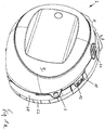
- FIGS. 1a . b shows a generally designated by the reference numeral 2 device for providing negative pressure for medical applications.
- the device 2 is portable on the body of a user (mobile operation), but it is also stationary operable (stationary operation). In mobile operation, the device could be carried along a belt, strap or the like and worn on the body, for this purpose, a fastening eye 3 is shown purely by way of example. In stationary operation, the device is adjustable to a preferably flat surface.
- the device 2 comprises a first housing part 4, in which a negative pressure generating device and electrical and electronic control components for the device (2) are included in total, including batteries or preferably rechargeable batteries.
- the device 2 comprises a second housing part 6, which is formed by a container 8 for receiving body fluids in its interior, in particular for receiving wound secretions extracted from a wound.
- the container 8 is designed as a disposable disposable article.
- the container 8 comprises above connecting pieces 10, 12 for a suction line, not shown, and a line for supplying media in the direction of the body of the patient or to form a measuring channel.
- the suction line, not shown then leads in the exemplary operation of the device for negative pressure wounds to a wound compressing the wound wound dressing and communicates there, for example via a port, with a wound space to create negative pressure in the wound space, maintain or vary and wound secretions in the Vacuum container 8.
- the container 8 communicates with the negative pressure generating device in the first housing part. 4
- the connecting piece 12 also leads via a line, not shown, which forms a measuring or flushing channel, towards the body the user, in particular to a wound.
- the connecting piece 12 communicates through the interior of the container 8 with the first housing part 4 and is from there with a supply medium, in particular flushing medium, acted upon or in communication with a measuring connection.
- connection piece 10 for the suction line opens into the interior of the container 8.
- the interior of the container 8 communicates via a vacuum interface 14 (to be described in more detail).
- FIG. 3 . 4a with the negative pressure generating device within the first housing part 4, when the container 8 in the in FIG. 1 shown operating position is fixed to the first housing part 4.
- the container 8 is manually positionable on the first housing part 4 and then manually in a mechanically fixed and mechanically releasable mounting position, in particular latching brought.
- the container 8 comprises a first housing part 4 facing the half-shell part 20 and a second remote from the first housing part 4 in mobile operation to the body of the user can be applied second half-shell part 22 (Fig. Figures 5 . 6 ) which, when assembled, confine the interior of the container (8).
- the container 8 further comprises an engagement opening 24, which is formed in the case exemplified as passing through the container 8 through-opening and is formed by two half-shell parts 20, 22 or limited.
- the engagement opening 24 is formed in the first container 8 approximately in an upper quarter and in the middle, so that a center of gravity of the container and the device is located approximately approximately below the engagement opening 24.
- the container 8 and also the entire device can be grasped by manual intervention in the engagement opening 24 with the fingers of a user.
- the user grasps by hand a relatively wide web 26 formed above the engagement opening 24, which forms a grip area.
- an unlocking 27 FIG. 1a
- the container from his in FIG. 1a shown operating position can be solved on the first housing part 4 and lifted off obliquely above. This too is in DE 2009 038 130.9 so that reference is hereby made for disclosure purposes.
- the interior of the container 8 extends into a region 28 adjacent to a wall 30 bounding the engagement opening 24.
- this region 28 is formed above a wall 30 delimiting the engagement opening 24 upwardly.
- This area 28 is bounded or formed by a chamber 32 that is so sealed, ie, sealed off, that it does not communicate with other adjacent chambers or areas inside the container 8. This means that in a liquid collecting chamber 33 in the interior of the container 8 sucked body fluid, in particular from a wound sucked wound secretion, even when tilting or momentary tilting of the container 8 can not penetrate into this chamber 32.
- the chamber 32 forms a kind of privacy in the area of the engagement opening 24 and in the region of the encompassable web 26.
- this chamber 32 overhangs the engagement opening 24 in the vertical direction 34 when viewed from above.
- the chamber 32 also extends in the direction of the arrows 36 to two opposite sides over the engagement opening 24 of time.
- the chamber 32 also extends adjacent to the engagement opening 24 laterally bounding wall 38. It is limited there to the outside by a wall 42 having a chamber 40 for receiving a Filters forms.
- the filter receiving chamber 40 is not completed in terms of flow. It communicates on the one hand with the negative pressure generating device in the first housing part 4 and on the other via a vacuum communicating opening 44 in the wall 42 with an antechamber 45.
- the second half-shell part 22 is formed with respect to the walls perpendicular to the parting plane complementary to the first half-shell part 20 , You can see in FIG. 5 a wall 42 'complementary to the wall 42.
- a negative pressure in the interior of the container 8 are constructed. Since the connecting piece 10 opens directly into the interior of the container 8, on the one hand a negative pressure can be applied to a wound via the suction line, not shown, and on the other hand body fluid can be sucked from there into the interior of the container 8.
- the further connecting piece 12 opens, viewed from the outside, into a further chamber 48, which is closed off from the remaining interior of the container 8 and is bounded by walls 50 which are closed in the peripheral direction and 50 'of the two half-shell parts 20, 22. From this chamber 48 leads in the depth direction, ie perpendicular to the parting plane, a passage 52 in the direction of the first housing part 4, that is again to the outside of the container eighth
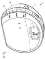
- FIG. 3 and 4 show the first half-shell part 20 from the outside, ie with a view to the first housing part 4 in the operating position facing side.
- Figures 3 and 4a show that to the first Half-shell part 20 from the outside to seal the chamber 40 for the filter and for sealing the passage channel 52, a sealing element 54 and 56 can preferably be molded directly.
- the narrow channel 58 is a feed section of injection molding material, whereby a web 60 connecting the two sealing elements 54, 56 is formed.
- FIG. 4a in that the sealing elements 54, 56 have an outwardly projecting concentric, cylindrical portion.
- Ribs 70 of a first type extend substantially in the vertical direction 72, that is in the direction of the arrow 34, within the liquid collection chamber 33. They terminate at a distance 74, preferably at least 5 mm, so that the liquid will tilt when the container 8 is inclined can be evenly distributed in the interior of the container with regular suction of the liquid through the connecting piece 10.
- ribs 76 of a second oblique type With the help of these ribs sloshing of the liquid received in the container 8 is prevented in the direction of the filter chamber 40. Such a rib 76 limits the previously mentioned prechamber 45 to the filter chamber 40.
- ribs 80 of a third type which are recirculated to each other in the circumferential direction. They form e.g. the wall 42 for the chamber 40 or the wall 50 for the chamber 48. Also, the circumferentially self-guided wall 30 defining the engagement opening 24 may be referred to as rib 80 of the third type.
- a passage opening 84 is provided for pressure equalization and gas passage at the very top, so that no air must be passed through the liquid.
- the two half-shell parts 20, 22 are preferably non-detachably and sealingly joined to one another by gluing or thermal welding and thus form the second housing part 6 of the device 2 forming container 8.
- a grippable web or grip region 26 is protected from contamination by body fluid accommodated inside the container 8;
- a privacy screen is thereby formed which, viewed from above, partially or preferably completely overhangs the area of the engagement opening 24.
- Figure 7a shows the arrangement of the filter 100 in the container 8. It can be seen that the filter 100 in an axial direction 102, which also corresponds to the joining direction of the half-shell parts 20, 22 and perpendicular to a dividing plane 104 between the half-shell parts 20, 22, between the Seal member 54 and an inner portion 106 of the half-shell part 22 is arranged.
- This inner region 106 is preferably formed by preferably a plurality of ribs 108, which also consist of FIG. 5 are particularly clear. They also advantageously extend in the axial direction 102 and preferably In addition, radially to the axial direction 102.
- the filter 100 has, for example, a pot-shaped shape, wherein it is supported axially against the ribs 108 with the outside of the pot bottom 110.
- the sealing member 54 is formed of an elastically yielding material. It is arranged in a through-opening 112 in a wall 114 of the first half-shell part 20 of the container 8, preferably in that it is injection-molded directly there.
- the sealing element 54 is preferably formed concentrically and comprises a passage opening 115 and therein a step 116, against which the filter 100 abuts in the axial direction 102. In this case, the sealing element 54 is slightly deformed, whereby an acting in the axial direction 102 clamping force results, which keeps the filter 100 in its intended mounting position.
- the sealing element 54 comprises a projecting into the interior of the container 8 tubular extension 118, in which the filter 100 engages axially.
- the inner diameter of the tubular extension 118 is matched to the outer circumference of the filter 100 in such a way that it is fixed in a clamping and frictional engagement therein, which facilitates the joining together of the half-shell parts 20, 24.
- the sealing element 54 comprises a tubular extension 120 projecting from the container 8 in the direction of the first housing part 4, by means of which a flow connection to the negative pressure generating device can be produced in the first housing part 4.
- the tubular extension 120 can automatically be applied sealingly against a cone-shaped approach, for example, and forming a flow connection when the container 8 is brought into its intended mounting position on the first housing part 4.
- FIG. 7b shows one Figure 7a corresponding sectional view, however, with opposite viewing direction by the further sealing element 56, as in FIGS. 4b, c is shown formed.
- the sealing element 54 has a tubular extension 122, 124. Its passage 52 opens into the above-mentioned chamber 48, the is sealed relative to the remaining interior of the container 8 and via the connecting piece 12 ( FIG. 2 ) communicates with a rinsing or measuring line, not shown.
- Both sealing elements 54, 56 are preferably produced in the same injection molding process and molded directly onto the first half-shell part 20. In order to have to provide only a bleed in an injection mold to be used for this purpose, the two sealing elements 54, 56 are connected via a common filling section 126, which is therefore filled with elastomeric material (s. FIGS. 4 ).
Landscapes
- Health & Medical Sciences (AREA)
- Heart & Thoracic Surgery (AREA)
- Vascular Medicine (AREA)
- Engineering & Computer Science (AREA)
- Anesthesiology (AREA)
- Biomedical Technology (AREA)
- Hematology (AREA)
- Life Sciences & Earth Sciences (AREA)
- Animal Behavior & Ethology (AREA)
- General Health & Medical Sciences (AREA)
- Public Health (AREA)
- Veterinary Medicine (AREA)
- External Artificial Organs (AREA)
Priority Applications (1)
| Application Number | Priority Date | Filing Date | Title |
|---|---|---|---|
| PL14720594T PL2991696T3 (pl) | 2013-05-03 | 2014-04-29 | Pojemnik do umieszczania płynów dla urządzenia do wytwarzania podciśnienia dla zastosowań medycznych, sposób wytwarzania zbiornika oraz urządzenie |
Applications Claiming Priority (2)
| Application Number | Priority Date | Filing Date | Title |
|---|---|---|---|
| DE102013208108.1A DE102013208108A1 (de) | 2013-05-03 | 2013-05-03 | Flüssigkeitsaufnahmebehälter für eine Vorrichtung zur Bereitstellung von Unterdruck für medizinischeAnwendungen, Verfahren zur Herstellung des Behälters, sowie Vorrichtung |
| PCT/EP2014/058691 WO2014177545A1 (de) | 2013-05-03 | 2014-04-29 | Flüssigkeitsaufnahmebehälter für eine vorrichtung zur bereitstellung von unterdruck für medizinische anwendungen, verfahren zur herstellung des behälters, sowie vorrichtung |
Publications (2)
| Publication Number | Publication Date |
|---|---|
| EP2991696A1 EP2991696A1 (de) | 2016-03-09 |
| EP2991696B1 true EP2991696B1 (de) | 2017-07-05 |
Family
ID=50628814
Family Applications (1)
| Application Number | Title | Priority Date | Filing Date |
|---|---|---|---|
| EP14720594.2A Active EP2991696B1 (de) | 2013-05-03 | 2014-04-29 | Flüssigkeitsaufnahmebehälter für eine vorrichtung zur bereitstellung von unterdruck für medizinische anwendungen, verfahren zur herstellung des behälters, sowie vorrichtung |
Country Status (8)
| Country | Link |
|---|---|
| US (1) | US20160045647A1 (pl) |
| EP (1) | EP2991696B1 (pl) |
| CN (1) | CN105188793B (pl) |
| DE (1) | DE102013208108A1 (pl) |
| ES (1) | ES2639213T3 (pl) |
| PL (1) | PL2991696T3 (pl) |
| RU (1) | RU2015148335A (pl) |
| WO (1) | WO2014177545A1 (pl) |
Families Citing this family (13)
| Publication number | Priority date | Publication date | Assignee | Title |
|---|---|---|---|---|
| AU359280S (en) * | 2014-04-30 | 2014-12-08 | Talley Group Ltd | Negative pressure wound therapy pump |
| DE102015110432A1 (de) | 2015-06-29 | 2016-12-29 | Paul Hartmann Ag | Instillationsadapter für ein Unterdruckwundbehandlungssystem |
| EP3124059B1 (de) | 2015-07-28 | 2018-12-05 | Paul Hartmann AG | Schalldämpfer für eine unterdrucktherapieeinheit |
| EP3124060B1 (de) | 2015-07-28 | 2019-09-11 | Paul Hartmann AG | Schalldämpfer für eine unterdrucktherapieeinheit |
| EP3187202B1 (en) | 2015-12-30 | 2019-09-25 | Paul Hartmann AG | Devices for controlling a negative pressure wound therapy system |
| EP3187204B1 (en) | 2015-12-30 | 2020-07-15 | Paul Hartmann AG | Methods and devices for controlling negative pressure wound therapy |
| EP3187203B2 (en) | 2015-12-30 | 2022-08-24 | Paul Hartmann AG | Methods and devices for controlling negative pressure at a wound site |
| EP3187205B1 (en) | 2015-12-30 | 2021-01-27 | Paul Hartmann AG | Methods and devices for performing a negative pressure wound therapy |
| EP3187206B1 (en) | 2015-12-30 | 2019-03-13 | Paul Hartmann AG | Methods and devices for negative pressure wound therapy |
| USD871568S1 (en) * | 2016-12-02 | 2019-12-31 | Kci Licensing, Inc. | Negative pressure apparatus module |
| USD903093S1 (en) | 2019-03-08 | 2020-11-24 | Kci Licensing, Inc. | Negative-pressure therapy device module |
| CN110115632A (zh) * | 2019-04-23 | 2019-08-13 | 美昕医疗器械(上海)有限公司 | 一种医疗废弃物收集设备的耗材盒 |
| IT202000014476A1 (it) * | 2020-06-17 | 2021-12-17 | Flaem Nuova Spa | Coperchio di chiusura per vasi di raccolta in sistemi aspiratori, relativo vaso di raccolta e relativo sistema aspiratore |
Family Cites Families (11)
| Publication number | Priority date | Publication date | Assignee | Title |
|---|---|---|---|---|
| ATE16350T1 (de) * | 1980-05-20 | 1985-11-15 | Haemonetics Corp | Fluessigkeitsabsaugapparat und flexibler beutel zur aufnahme von fluessigkeit, der zur verwendung in einem solchen apparat geeignet ist. |
| US4465485A (en) * | 1981-03-06 | 1984-08-14 | Becton, Dickinson And Company | Suction canister with unitary shut-off valve and filter features |
| DK1219311T3 (da) * | 1994-08-22 | 2004-08-30 | Kci Licensing Inc | Beholder |
| US6210383B1 (en) | 1999-01-29 | 2001-04-03 | Atrium Medical Corporation | Fluid recovery system |
| DK1960014T3 (en) * | 2005-12-14 | 2017-01-09 | Stryker Corp | Medical / surgical waste collection and disposal system |
| US8048047B2 (en) * | 2006-06-23 | 2011-11-01 | Novartis Ag | Surgical cassette with improved air filtering |
| CA2674036C (en) * | 2007-02-09 | 2017-01-10 | Kci Licensing, Inc. | System and method for applying reduced pressure at a tissue site |
| US8007481B2 (en) * | 2008-07-17 | 2011-08-30 | Tyco Healthcare Group Lp | Subatmospheric pressure mechanism for wound therapy system |
| WO2011008961A1 (en) * | 2009-07-15 | 2011-01-20 | Allegiance Corporation | Fluid collection and disposal system and related methods |
| DE102009038131A1 (de) * | 2009-08-12 | 2011-02-17 | ATMOS Medizin Technik GmbH & Co. KG | Am Körper eines Benutzers tragbare Vorrichtung zur Bereitstellung von Unterdruck für medizinische Anwendungen |
| DE102009038130A1 (de) * | 2009-08-12 | 2011-02-17 | ATMOS Medizin Technik GmbH & Co. KG | Am Körper eines Benutzers tragbare Vorrichtung zur Bereitstellung von Unterdruck für medizinische Anwendungen |
-
2013
- 2013-05-03 DE DE102013208108.1A patent/DE102013208108A1/de not_active Withdrawn
-
2014
- 2014-04-29 ES ES14720594.2T patent/ES2639213T3/es active Active
- 2014-04-29 PL PL14720594T patent/PL2991696T3/pl unknown
- 2014-04-29 CN CN201480025122.4A patent/CN105188793B/zh active Active
- 2014-04-29 US US14/784,291 patent/US20160045647A1/en not_active Abandoned
- 2014-04-29 WO PCT/EP2014/058691 patent/WO2014177545A1/de not_active Ceased
- 2014-04-29 RU RU2015148335A patent/RU2015148335A/ru not_active Application Discontinuation
- 2014-04-29 EP EP14720594.2A patent/EP2991696B1/de active Active
Also Published As
| Publication number | Publication date |
|---|---|
| DE102013208108A8 (de) | 2015-01-15 |
| ES2639213T3 (es) | 2017-10-25 |
| CN105188793B (zh) | 2017-03-29 |
| RU2015148335A (ru) | 2017-06-08 |
| CN105188793A (zh) | 2015-12-23 |
| PL2991696T3 (pl) | 2017-11-30 |
| EP2991696A1 (de) | 2016-03-09 |
| RU2015148335A3 (pl) | 2018-02-28 |
| DE102013208108A1 (de) | 2014-11-20 |
| US20160045647A1 (en) | 2016-02-18 |
| WO2014177545A1 (de) | 2014-11-06 |
Similar Documents
| Publication | Publication Date | Title |
|---|---|---|
| WO2014177545A1 (de) | Flüssigkeitsaufnahmebehälter für eine vorrichtung zur bereitstellung von unterdruck für medizinische anwendungen, verfahren zur herstellung des behälters, sowie vorrichtung | |
| EP2991697A1 (de) | Flüssigkeitsaufnahmebehälter für eine vorrichtung zur bereitstellung von unterdruck für medizinische anwendungen, sowie vorrichtung | |
| EP2427229B1 (de) | Drainageschlauchvorrichtung und kupplungseinheit | |
| EP3700603B1 (de) | Brustpumpe | |
| DE2824588C2 (de) | Verschließvorrichtung für ein Vakuumröhrchen zur Blutentnahme | |
| EP1278488B1 (de) | Aufbereitungs-und applikationsvorrichtung für zu einer pastösen fliessfähigen masse aufzubereitende materialen, insbesondere knochenzement | |
| DE202015102280U1 (de) | Anordnung mit einer Wanddurchführung für mehrere Kabel und Bausatz | |
| WO1995016395A1 (de) | Haltevorrichtung für ein blutprobenentnahmeröhrchen einer blutabnahmevorrichtung | |
| DE3029886A1 (de) | Blutentnahmegeraet | |
| EP1894831B1 (de) | Bremssystem mit einer hydraulischen Bremsanlage | |
| EP2536448A1 (de) | Kopplungsteil einer drainageschlaucheinheit | |
| EP1908659A2 (de) | Bremssystem mit einer hydraulischen Bremsanlage | |
| EP1843140A2 (de) | Anschlusselement zur lösbaren abgedichteten Verbindung eines Fluidleitungssystems mit einem Druckaufnehmer und Druckaufnehmer hierzu | |
| DE102011004035A1 (de) | Pulverpumpe zum Fördern von Beschichtungspulver | |
| EP2310066A2 (de) | Fluidsammelbehälter | |
| DE202013105808U1 (de) | Vorrichtung zur Entnahme von medizinischen Flüssigkeiten aus dafür vorgesehenen Vorratsbehältern mittels Spritzen | |
| DE60029623T2 (de) | Einheit für mikrobiologische prüfung einer flüssigen probe unter druck und verfharen für das leeren dieser einheit | |
| DE69020170T2 (de) | Apparat zum beschichten der oberfläche und der seitenkanten einer platte aus holz oder ähnlichem material mit einer wärmeverformbaren folie. | |
| EP3503935B1 (de) | Vorrichtung zur unterdruckbehandlung von wunden am menschlichen körper | |
| DE202012007884U1 (de) | Einweg-Ventileinrichtung | |
| EP2576057B1 (de) | Handbedienteil einer absaugvorrichtung | |
| DE102022101151A1 (de) | Kappe für einen Konnektor eines enteralen Überleitungssets sowie Überleitungsset mit einer Kappe | |
| DE29601812U1 (de) | Anschlußstück eines Filterbeutels für Staubsauger | |
| EP3692880B1 (de) | Handgeführter zyklon-staubsauger | |
| DE202008010652U1 (de) | Milchabsaugvorrichtung |
Legal Events
| Date | Code | Title | Description |
|---|---|---|---|
| PUAI | Public reference made under article 153(3) epc to a published international application that has entered the european phase |
Free format text: ORIGINAL CODE: 0009012 |
|
| 17P | Request for examination filed |
Effective date: 20150911 |
|
| AK | Designated contracting states |
Kind code of ref document: A1 Designated state(s): AL AT BE BG CH CY CZ DE DK EE ES FI FR GB GR HR HU IE IS IT LI LT LU LV MC MK MT NL NO PL PT RO RS SE SI SK SM TR |
|
| AX | Request for extension of the european patent |
Extension state: BA ME |
|
| RIN1 | Information on inventor provided before grant (corrected) |
Inventor name: ECKSTEIN, AXEL Inventor name: FONFARA-DOERR, ASTRID Inventor name: MAHLER, ANDREAS Inventor name: CROIZAT, PIERRE Inventor name: KIRSTEN, JUANA |
|
| DAX | Request for extension of the european patent (deleted) | ||
| GRAP | Despatch of communication of intention to grant a patent |
Free format text: ORIGINAL CODE: EPIDOSNIGR1 |
|
| INTG | Intention to grant announced |
Effective date: 20170202 |
|
| RIN1 | Information on inventor provided before grant (corrected) |
Inventor name: ECKSTEIN, AXEL Inventor name: FONFARA-DOERR, ASTRID Inventor name: KIRSTEN, JUANA Inventor name: MAHLER, ANDREAS Inventor name: CROIZAT, PIERRE |
|
| GRAS | Grant fee paid |
Free format text: ORIGINAL CODE: EPIDOSNIGR3 |
|
| GRAA | (expected) grant |
Free format text: ORIGINAL CODE: 0009210 |
|
| AK | Designated contracting states |
Kind code of ref document: B1 Designated state(s): AL AT BE BG CH CY CZ DE DK EE ES FI FR GB GR HR HU IE IS IT LI LT LU LV MC MK MT NL NO PL PT RO RS SE SI SK SM TR |
|
| REG | Reference to a national code |
Ref country code: GB Ref legal event code: FG4D Free format text: NOT ENGLISH |
|
| REG | Reference to a national code |
Ref country code: CH Ref legal event code: EP |
|
| REG | Reference to a national code |
Ref country code: AT Ref legal event code: REF Ref document number: 906138 Country of ref document: AT Kind code of ref document: T Effective date: 20170715 |
|
| REG | Reference to a national code |
Ref country code: IE Ref legal event code: FG4D Free format text: LANGUAGE OF EP DOCUMENT: GERMAN |
|
| REG | Reference to a national code |
Ref country code: DE Ref legal event code: R096 Ref document number: 502014004487 Country of ref document: DE |
|
| REG | Reference to a national code |
Ref country code: SE Ref legal event code: TRGR |
|
| REG | Reference to a national code |
Ref country code: ES Ref legal event code: FG2A Ref document number: 2639213 Country of ref document: ES Kind code of ref document: T3 Effective date: 20171025 |
|
| REG | Reference to a national code |
Ref country code: NL Ref legal event code: MP Effective date: 20170705 |
|
| REG | Reference to a national code |
Ref country code: LT Ref legal event code: MG4D |
|
| PG25 | Lapsed in a contracting state [announced via postgrant information from national office to epo] |
Ref country code: NL Free format text: LAPSE BECAUSE OF FAILURE TO SUBMIT A TRANSLATION OF THE DESCRIPTION OR TO PAY THE FEE WITHIN THE PRESCRIBED TIME-LIMIT Effective date: 20170705 Ref country code: LT Free format text: LAPSE BECAUSE OF FAILURE TO SUBMIT A TRANSLATION OF THE DESCRIPTION OR TO PAY THE FEE WITHIN THE PRESCRIBED TIME-LIMIT Effective date: 20170705 Ref country code: FI Free format text: LAPSE BECAUSE OF FAILURE TO SUBMIT A TRANSLATION OF THE DESCRIPTION OR TO PAY THE FEE WITHIN THE PRESCRIBED TIME-LIMIT Effective date: 20170705 Ref country code: NO Free format text: LAPSE BECAUSE OF FAILURE TO SUBMIT A TRANSLATION OF THE DESCRIPTION OR TO PAY THE FEE WITHIN THE PRESCRIBED TIME-LIMIT Effective date: 20171005 Ref country code: HR Free format text: LAPSE BECAUSE OF FAILURE TO SUBMIT A TRANSLATION OF THE DESCRIPTION OR TO PAY THE FEE WITHIN THE PRESCRIBED TIME-LIMIT Effective date: 20170705 |
|
| PG25 | Lapsed in a contracting state [announced via postgrant information from national office to epo] |
Ref country code: GR Free format text: LAPSE BECAUSE OF FAILURE TO SUBMIT A TRANSLATION OF THE DESCRIPTION OR TO PAY THE FEE WITHIN THE PRESCRIBED TIME-LIMIT Effective date: 20171006 Ref country code: RS Free format text: LAPSE BECAUSE OF FAILURE TO SUBMIT A TRANSLATION OF THE DESCRIPTION OR TO PAY THE FEE WITHIN THE PRESCRIBED TIME-LIMIT Effective date: 20170705 Ref country code: BG Free format text: LAPSE BECAUSE OF FAILURE TO SUBMIT A TRANSLATION OF THE DESCRIPTION OR TO PAY THE FEE WITHIN THE PRESCRIBED TIME-LIMIT Effective date: 20171005 Ref country code: LV Free format text: LAPSE BECAUSE OF FAILURE TO SUBMIT A TRANSLATION OF THE DESCRIPTION OR TO PAY THE FEE WITHIN THE PRESCRIBED TIME-LIMIT Effective date: 20170705 Ref country code: IS Free format text: LAPSE BECAUSE OF FAILURE TO SUBMIT A TRANSLATION OF THE DESCRIPTION OR TO PAY THE FEE WITHIN THE PRESCRIBED TIME-LIMIT Effective date: 20171105 |
|
| REG | Reference to a national code |
Ref country code: DE Ref legal event code: R097 Ref document number: 502014004487 Country of ref document: DE |
|
| REG | Reference to a national code |
Ref country code: FR Ref legal event code: PLFP Year of fee payment: 5 |
|
| PG25 | Lapsed in a contracting state [announced via postgrant information from national office to epo] |
Ref country code: RO Free format text: LAPSE BECAUSE OF FAILURE TO SUBMIT A TRANSLATION OF THE DESCRIPTION OR TO PAY THE FEE WITHIN THE PRESCRIBED TIME-LIMIT Effective date: 20170705 Ref country code: DK Free format text: LAPSE BECAUSE OF FAILURE TO SUBMIT A TRANSLATION OF THE DESCRIPTION OR TO PAY THE FEE WITHIN THE PRESCRIBED TIME-LIMIT Effective date: 20170705 |
|
| PLBE | No opposition filed within time limit |
Free format text: ORIGINAL CODE: 0009261 |
|
| STAA | Information on the status of an ep patent application or granted ep patent |
Free format text: STATUS: NO OPPOSITION FILED WITHIN TIME LIMIT |
|
| PG25 | Lapsed in a contracting state [announced via postgrant information from national office to epo] |
Ref country code: SK Free format text: LAPSE BECAUSE OF FAILURE TO SUBMIT A TRANSLATION OF THE DESCRIPTION OR TO PAY THE FEE WITHIN THE PRESCRIBED TIME-LIMIT Effective date: 20170705 Ref country code: EE Free format text: LAPSE BECAUSE OF FAILURE TO SUBMIT A TRANSLATION OF THE DESCRIPTION OR TO PAY THE FEE WITHIN THE PRESCRIBED TIME-LIMIT Effective date: 20170705 Ref country code: SM Free format text: LAPSE BECAUSE OF FAILURE TO SUBMIT A TRANSLATION OF THE DESCRIPTION OR TO PAY THE FEE WITHIN THE PRESCRIBED TIME-LIMIT Effective date: 20170705 |
|
| 26N | No opposition filed |
Effective date: 20180406 |
|
| PG25 | Lapsed in a contracting state [announced via postgrant information from national office to epo] |
Ref country code: SI Free format text: LAPSE BECAUSE OF FAILURE TO SUBMIT A TRANSLATION OF THE DESCRIPTION OR TO PAY THE FEE WITHIN THE PRESCRIBED TIME-LIMIT Effective date: 20170705 |
|
| PG25 | Lapsed in a contracting state [announced via postgrant information from national office to epo] |
Ref country code: MT Free format text: LAPSE BECAUSE OF FAILURE TO SUBMIT A TRANSLATION OF THE DESCRIPTION OR TO PAY THE FEE WITHIN THE PRESCRIBED TIME-LIMIT Effective date: 20170705 |
|
| PG25 | Lapsed in a contracting state [announced via postgrant information from national office to epo] |
Ref country code: MC Free format text: LAPSE BECAUSE OF FAILURE TO SUBMIT A TRANSLATION OF THE DESCRIPTION OR TO PAY THE FEE WITHIN THE PRESCRIBED TIME-LIMIT Effective date: 20170705 |
|
| REG | Reference to a national code |
Ref country code: CH Ref legal event code: PL |
|
| REG | Reference to a national code |
Ref country code: SE Ref legal event code: EUG |
|
| REG | Reference to a national code |
Ref country code: BE Ref legal event code: MM Effective date: 20180430 |
|
| GBPC | Gb: european patent ceased through non-payment of renewal fee |
Effective date: 20180429 |
|
| REG | Reference to a national code |
Ref country code: IE Ref legal event code: MM4A |
|
| PG25 | Lapsed in a contracting state [announced via postgrant information from national office to epo] |
Ref country code: CZ Free format text: LAPSE BECAUSE OF NON-PAYMENT OF DUE FEES Effective date: 20180429 Ref country code: LU Free format text: LAPSE BECAUSE OF NON-PAYMENT OF DUE FEES Effective date: 20180429 Ref country code: SE Free format text: LAPSE BECAUSE OF NON-PAYMENT OF DUE FEES Effective date: 20180430 |
|
| PG25 | Lapsed in a contracting state [announced via postgrant information from national office to epo] |
Ref country code: BE Free format text: LAPSE BECAUSE OF NON-PAYMENT OF DUE FEES Effective date: 20180430 Ref country code: GB Free format text: LAPSE BECAUSE OF NON-PAYMENT OF DUE FEES Effective date: 20180429 Ref country code: CH Free format text: LAPSE BECAUSE OF NON-PAYMENT OF DUE FEES Effective date: 20180430 Ref country code: LI Free format text: LAPSE BECAUSE OF NON-PAYMENT OF DUE FEES Effective date: 20180430 |
|
| PG25 | Lapsed in a contracting state [announced via postgrant information from national office to epo] |
Ref country code: IT Free format text: LAPSE BECAUSE OF NON-PAYMENT OF DUE FEES Effective date: 20180429 Ref country code: IE Free format text: LAPSE BECAUSE OF NON-PAYMENT OF DUE FEES Effective date: 20180429 |
|
| PG25 | Lapsed in a contracting state [announced via postgrant information from national office to epo] |
Ref country code: PL Free format text: LAPSE BECAUSE OF NON-PAYMENT OF DUE FEES Effective date: 20180429 |
|
| PG25 | Lapsed in a contracting state [announced via postgrant information from national office to epo] |
Ref country code: PT Free format text: LAPSE BECAUSE OF FAILURE TO SUBMIT A TRANSLATION OF THE DESCRIPTION OR TO PAY THE FEE WITHIN THE PRESCRIBED TIME-LIMIT Effective date: 20170705 |
|
| PG25 | Lapsed in a contracting state [announced via postgrant information from national office to epo] |
Ref country code: CY Free format text: LAPSE BECAUSE OF FAILURE TO SUBMIT A TRANSLATION OF THE DESCRIPTION OR TO PAY THE FEE WITHIN THE PRESCRIBED TIME-LIMIT Effective date: 20170705 Ref country code: HU Free format text: LAPSE BECAUSE OF FAILURE TO SUBMIT A TRANSLATION OF THE DESCRIPTION OR TO PAY THE FEE WITHIN THE PRESCRIBED TIME-LIMIT; INVALID AB INITIO Effective date: 20140429 Ref country code: MK Free format text: LAPSE BECAUSE OF NON-PAYMENT OF DUE FEES Effective date: 20170705 |
|
| PG25 | Lapsed in a contracting state [announced via postgrant information from national office to epo] |
Ref country code: AL Free format text: LAPSE BECAUSE OF FAILURE TO SUBMIT A TRANSLATION OF THE DESCRIPTION OR TO PAY THE FEE WITHIN THE PRESCRIBED TIME-LIMIT Effective date: 20170705 |
|
| REG | Reference to a national code |
Ref country code: AT Ref legal event code: MM01 Ref document number: 906138 Country of ref document: AT Kind code of ref document: T Effective date: 20190429 |
|
| PG25 | Lapsed in a contracting state [announced via postgrant information from national office to epo] |
Ref country code: AT Free format text: LAPSE BECAUSE OF NON-PAYMENT OF DUE FEES Effective date: 20190429 |
|
| P01 | Opt-out of the competence of the unified patent court (upc) registered |
Effective date: 20230518 |
|
| PG25 | Lapsed in a contracting state [announced via postgrant information from national office to epo] |
Ref country code: TR Free format text: LAPSE BECAUSE OF NON-PAYMENT OF DUE FEES Effective date: 20180429 |
|
| PGFP | Annual fee paid to national office [announced via postgrant information from national office to epo] |
Ref country code: DE Payment date: 20250417 Year of fee payment: 12 |
|
| PGFP | Annual fee paid to national office [announced via postgrant information from national office to epo] |
Ref country code: ES Payment date: 20250519 Year of fee payment: 12 |
|
| PGFP | Annual fee paid to national office [announced via postgrant information from national office to epo] |
Ref country code: FR Payment date: 20250424 Year of fee payment: 12 |