EP2991237B1 - Basis station und massives mimo-kommunikationsverfahren - Google Patents
Basis station und massives mimo-kommunikationsverfahren Download PDFInfo
- Publication number
- EP2991237B1 EP2991237B1 EP15182233.5A EP15182233A EP2991237B1 EP 2991237 B1 EP2991237 B1 EP 2991237B1 EP 15182233 A EP15182233 A EP 15182233A EP 2991237 B1 EP2991237 B1 EP 2991237B1
- Authority
- EP
- European Patent Office
- Prior art keywords
- matrix
- base station
- formula
- transmission signal
- gain
- Prior art date
- Legal status (The legal status is an assumption and is not a legal conclusion. Google has not performed a legal analysis and makes no representation as to the accuracy of the status listed.)
- Not-in-force
Links
Images


Classifications
-
- H—ELECTRICITY
- H04—ELECTRIC COMMUNICATION TECHNIQUE
- H04B—TRANSMISSION
- H04B7/00—Radio transmission systems, i.e. using radiation field
- H04B7/02—Diversity systems; Multi-antenna system, i.e. transmission or reception using multiple antennas
- H04B7/04—Diversity systems; Multi-antenna system, i.e. transmission or reception using multiple antennas using two or more spaced independent antennas
- H04B7/0413—MIMO systems
- H04B7/0456—Selection of precoding matrices or codebooks, e.g. using matrices antenna weighting
-
- H—ELECTRICITY
- H04—ELECTRIC COMMUNICATION TECHNIQUE
- H04B—TRANSMISSION
- H04B7/00—Radio transmission systems, i.e. using radiation field
- H04B7/02—Diversity systems; Multi-antenna system, i.e. transmission or reception using multiple antennas
- H04B7/04—Diversity systems; Multi-antenna system, i.e. transmission or reception using multiple antennas using two or more spaced independent antennas
- H04B7/06—Diversity systems; Multi-antenna system, i.e. transmission or reception using multiple antennas using two or more spaced independent antennas at the transmitting station
- H04B7/0613—Diversity systems; Multi-antenna system, i.e. transmission or reception using multiple antennas using two or more spaced independent antennas at the transmitting station using simultaneous transmission
- H04B7/0615—Diversity systems; Multi-antenna system, i.e. transmission or reception using multiple antennas using two or more spaced independent antennas at the transmitting station using simultaneous transmission of weighted versions of same signal
- H04B7/0617—Diversity systems; Multi-antenna system, i.e. transmission or reception using multiple antennas using two or more spaced independent antennas at the transmitting station using simultaneous transmission of weighted versions of same signal for beam forming
-
- H—ELECTRICITY
- H04—ELECTRIC COMMUNICATION TECHNIQUE
- H04B—TRANSMISSION
- H04B7/00—Radio transmission systems, i.e. using radiation field
- H04B7/02—Diversity systems; Multi-antenna system, i.e. transmission or reception using multiple antennas
- H04B7/04—Diversity systems; Multi-antenna system, i.e. transmission or reception using multiple antennas using two or more spaced independent antennas
- H04B7/06—Diversity systems; Multi-antenna system, i.e. transmission or reception using multiple antennas using two or more spaced independent antennas at the transmitting station
- H04B7/0686—Hybrid systems, i.e. switching and simultaneous transmission
- H04B7/0691—Hybrid systems, i.e. switching and simultaneous transmission using subgroups of transmit antennas
-
- H—ELECTRICITY
- H04—ELECTRIC COMMUNICATION TECHNIQUE
- H04B—TRANSMISSION
- H04B7/00—Radio transmission systems, i.e. using radiation field
- H04B7/02—Diversity systems; Multi-antenna system, i.e. transmission or reception using multiple antennas
- H04B7/04—Diversity systems; Multi-antenna system, i.e. transmission or reception using multiple antennas using two or more spaced independent antennas
- H04B7/08—Diversity systems; Multi-antenna system, i.e. transmission or reception using multiple antennas using two or more spaced independent antennas at the receiving station
- H04B7/0837—Diversity systems; Multi-antenna system, i.e. transmission or reception using multiple antennas using two or more spaced independent antennas at the receiving station using pre-detection combining
- H04B7/0842—Weighted combining
- H04B7/0865—Independent weighting, i.e. weights based on own antenna reception parameters
-
- H—ELECTRICITY
- H04—ELECTRIC COMMUNICATION TECHNIQUE
- H04W—WIRELESS COMMUNICATION NETWORKS
- H04W88/00—Devices specially adapted for wireless communication networks, e.g. terminals, base stations or access point devices
- H04W88/08—Access point devices
Definitions
- the present invention relates generally, but not exclusively to a base station for wireless communications, and massive MIMO communication method.
- the amount of wireless communications by a portable or mobile terminal is increasing explosively by the propagation of smart phones. From now on, the form of the communication performed between apparatuses, not via a person, is also assumed as wireless communication. For this reason, the traffic amount of wireless communications may increase by 1,000-10,000 times in and after 2020, compared with the present. Therefore, research of a new communication system is actively underway. Manufacturers developing a radiotelephone system have previously focused their efforts to further improve the frequency usage efficiency of the radiotelephone system, rather than in the Long Term Evolution (LTE) and LTE-Advanced (LTE-A) communication systems of with which the business is done now.
- LTE Long Term Evolution
- LTE-A LTE-Advanced
- One of the leading techniques is a massive multiple-input and multiple-output (MIMO) communication system, which is generally a base station equipped with about one hundred antennas, and communicates with about ten sets of mobile terminals simultaneously.
- MIMO massive multiple-input and multiple-output
- the frequency usage efficiency can be maintained stably, without receiving most of the noise of a communication channel or the influence of early fading fluctuation.
- channel capacity increases greatly compared with a conventional MIMO communication system. Therefore, the massive MIMO communication system is leading as a next-generation new technology.
- the present disclosure provides a base station that includes a data control circuitry that processes a transmission signal to be simultaneously transmitted to a plurality of mobile terminals; a modulator circuitry that modulates the transmission signal processed by the data control circuitry; a radio frequency modulator circuitry that modulates the transmission signal modulated by the modulator circuitry into a radio frequency transmission signal; and a plurality of antennas that wirelessly transmit the radio frequency transmission signal to the plurality of mobile terminals.
- the data control circuitry multiplies the transmission signal by a precode matrix.
- the present disclosure is related to a massive MIMO communication system, where one base station is provided with hundreds of antennas to simultaneously perform wireless communication with dozens of mobile terminals.
- An object of this disclosure is to provide a massive MIMO communication system, which can remove interference of a signal transmitted from the base station to a terminal with small computational complexity. This is done by modulating the signal at the time of transmission from the base station by a precode, such that the signal received at each terminal is correlated with the terminal without requiring operations such as diagonalization etc. With such configuration, it becomes possible to increase the number of the mobile terminals with which the base station can simultaneously perform communication. Further, it becomes possible for the base station to modulate and transmit a signal with efficiency as high as in 16 Quadrature Amplitude Modulation (16QAM).
- 16QAM 16 Quadrature Amplitude Modulation
- a number of mobile terminals, or terminals, with which a base station simultaneously performs communication may be given by Nv
- the number of antennas of a base station may be given by Nb
- the channel matrix, which specifies the transmitting signal may be given as H, and becomes [Nv x Nb].
- H* is a conjugation-complex transposition of the channel matrix H.
- the base station factorizes a correlation matrix H ⁇ H*, which is the multiplication of the matrix H by a matrix H*, into a lower triangular matrix L and an upper triangular matrix U, to thereby obtain the upper triangular matrix U. Further, the base station multiplies the inverse matrix U -1 of the upper triangular matrix U by a transmission signal Tx having transmission data and transmits the result to the one or more mobile terminals in a transmission stream.
- the base station when multiplying by H* as precoding, the reception of each terminal becomes H ⁇ H* ⁇ (transmission data).
- non-diagonal elements of the correlation matrix H ⁇ H* become smaller compared with the diagonal elements if the correlation between different channels is low.
- the technique is characterized by the method of modulating a signal so that a mobile terminal, given by UE, receives a signal uniquely for that mobile terminal without performing an operation, such as diagonalization, or the like. Also, noise superimposed on a channel is reduced by the correlation matrix, because auto- and cross-correlation of the noise itself is low. Further, it becomes possible to perform reception that is less subject to the influence of signal noise as a result.
- the correlation matrix H ⁇ H* is given by G and the transmitting signal is given by Tx.
- the first term in the reception matrix (Tx 0 ⁇ ⁇ hjj 2 + Tx 1 ⁇ ⁇ hij ⁇ hkl* ) describes the reception signal of a first terminal UE#1.
- the 1st term is a signal that terminal UE#1 should receive.
- the signals that are meant for the other terminals UE#2, UE#3,... to receive are mixed as interference terms.
- the correlation is low, the addition result after the 2nd term becomes a very small value compared with the 1st term, and a correlation value shows a limited value.
- the interference term of a certain terminal increases only by the number of other terminals. Therefore, a sum of interference terms, or an interference amount, increases only because the number of terminals that the base station communicates simultaneously increases. When the sum of interference terms increases, the quality of the received signal worsens. In order to avoid this, the base station further needs to increase the number of antennas, whereby the total correlation value can be made smaller.
- An object of the present disclosure is to provide a communication method for massive MIMO communication. Multiple embodiments are disclosed in order to solve the above-described problem. As explained above, this disclosure triangular-factorizes a channel correlation matrix H ⁇ H*, and multiplies it to a transmitting signal by a precode matrix. In the preferred embodiment explained above, an inverse matrix U -1 of the upper triangular matrix U is set as the precode matrix.
- this disclosure multiplies each element U ij of the upper triangular matrix U of a triangular matrix by a gain gi, multiplies each element L ij of the lower triangular matrix L by a gain 1/gi, and sets the inverse matrix L -1 of the lower triangular matrix L as the precode matrix.
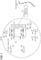
- FIG. 1 shows the system structure relating to the base station as an example of one embodiment of this disclosure.
- the base station 100 is connected to an external network 140 through a base station control unit 130.
- a cell 120 is a range that an electromagnetic wave from the base station 100 reaches.
- the base station 100 performs wireless communications with a plurality of mobile terminals 211,221,231,... 291 in the cell 120 with a massive MIMO communication system.
- a mobile terminal 211,221,231,... 291 may be in possession of a user, as well as a position in the cell 120 that moves with them at any time.
- the base station 100 is further equipped with a data control block 101, which receives the transmission signal or the transmission data.
- the transmission data obtained in the data control block 101 are supplied to respectively separate modulators 102A-102Nv, and are modulated.
- the signal modulated by each modulator 102A-102Nv is modulated by a transmit frequency by respectively separate radio frequency modulators 103A-103Nv, and is supplied to the antenna 111A-111Nb.
- the base station 100 transmits signals simultaneously from the antenna 111A-111Nb, and wireless communication is performed simultaneously with mobile terminals 211,221,231,... 291.
- Each mobile terminal 211,221,231,... 291 is equipped with at least one piece(s) of antenna 212,222,232,... 292 as an antenna for reception.
- the data control block 101, the base station control unit 130, the external network 140, the modulators 102A-102Nv, and the radio frequency modulators 103A-103Nv can be circuitry, such as a processing circuitry that is configured to execute one or more sequences of one or more instructions contained in a memory.
- One or more processors in a multi-processing arrangement may also be employed to execute the sequences of instructions contained in the memory.
- hard-wired circuitry may be used in place of or in combination with software instructions. Thus, embodiments are not limited to any specific combination of hardware circuitry and software.
- FIG. 2 shows an example of a structure of the antenna array 110.
- the antenna array 110 is equipped with Nb number of antenna 111A-111Nb.
- the antenna 111A-111Nb are arranged in a cylindrical shape, as shown.
- FIG. 3 shows an example of a structure of the base station 100 according to an exemplary embodiment.
- the base station 100 is shown equipped with the data control block 101.
- the transmission signal of the Nv terminals and the data of the [Nv x Nb] matrix, which determines the channel matrix H are supplied.
- the transmitting signal or data stream of the Nv-th terminal and the data of the [Nv x Nb] matrix are supplied to a correlation matrix calculation part 101a.
- the correlation matrix [HxH*] generated in the correlation matrix calculation part 101a is supplied to a LU decomposition part 101b.
- the LU decomposition part 101b decomposes the correlation matrix [HxH*] into the product of the lower triangular matrix L and the upper triangular matrix U.
- the upper triangular matrix U obtained in the LU decomposition part 101b is supplied to an inverse-matrix calculation part 101c.
- the inverse-matrix calculation part 101c generates the inverse matrix U -1 of the upper triangular matrix U by a calculation.
- the inverse upper triangular-matrix U -1 obtained in the inverse-matrix calculation part 101c is supplied to a precode generation part 101d.
- the precode generated in the precode generation part 101d is multiplied by the transmission data in a precode multiplication part 101e and the data stream of the Nv-th terminal is generated.
- the data stream of the Nv-th terminal obtained in the precode multiplication part 101e is supplied to respectively separate modulators 102A, 102B,..., 102Nv.
- This data stream of the Nv-th terminal is the data of the component of a column in number of Nv of the precode matrices [Nv x Nb] generated in the data control block 101.
- an input signal is supplied to an IFFT section 102a, which performs an reverse fast Fourier transformation (IFFT) process.
- the signal to which the IFFT process was performed is supplied to a CP addition part 102b, and a cyclic prefix CP is added.
- the signal to which the cyclic prefix CP was added in the CP addition part 102b is supplied to a parallel and serial conversion part 102c, and is converted into serial data.
- the serial data converted in the parallel and serial conversion part 102c are supplied to a baseband filter 102d.
- a waveform shaping process and the removal processing of quantized noise are performed.
- the signal which the baseband filter 102d outputs is supplied to respective radio frequency modulators 103A-103Nv.
- the baseband filter 102d outputs a signal by which Orthogonal Frequency Division Multiplexing (OFDM) modulation was carried out.
- the resulting transmitting signal is separated into an I component (In-phase) and an Q component (Quadrature) by the radio frequency modulators 103A-103Nv.
- OFDM Orthogonal Frequency Division Multiplexing
- a quadrature modulator QM modulates a transmit frequency carrier wave by the I component and the Q component, and then mixes the transmit frequency carrier wave with a transmitting signal.
- the resultant mixed transmitting signal is supplied to the antenna 111A-111Nb of each series through an amplifier (PA).
- PA amplifier
- the correlation matrix calculation part 101a, the LU decomposition part 101b, the inverse-matrix calculation part 101c, the precode generation part 101d, the IFFT section 102a, the CP addition part 102b, the parallel and serial conversion part 102c, and the baseband filter 102d can be circuitry, such as a processing circuitry that is configured to execute one or more sequences of one or more instructions contained in a memory.
- One or more processors in a multi-processing arrangement may also be employed to execute the sequences of instructions contained in the memory.
- hard-wired circuitry may be used in place of or in combination with software instructions. Thus, embodiments are not limited to any specific combination of hardware circuitry and software.
- the precode matrix PC is an inverse matrix of the upper triangular matrix U, when a correlation matrix [HxH*] is decomposed into the lower triangular matrix L and the upper triangular matrix U. That is, when Formula 3 holds, the precode matrix PC is given by Formula 4.
- L is a lower triangular matrix and U is an upper triangular matrix.
- Formula 7 shows the received signal Rx when Formula 6-1 is substituted into Formula 5, where the transmission data to the N-th terminal is given as TN.
- Rx l 00 0 0 ⁇ l 10 l 11 0 0 ⁇ l 20 l 21 l 22 0 ⁇ l 30 l 31 l 32 l 33 ⁇ ⁇ ⁇ ⁇ ⁇ ⁇ ⁇ ⁇ T 0 T 1 ⁇ ⁇ TN ⁇
- Formula 7 shows that there is no interference from another terminal at an 0-th terminal (UE#0).
- UE#1 the transmission data to the UE#0 is interfering.
- the last terminal UE# (Nv-1) receives interference from other all terminals.
- the lower triangular matrix L can reduce the interference amount as a whole.
- a new lower triangular matrix L new in Formula 8-1 is used in place of the lower triangular matrix L of Formula 6-1.
- L ne w k l 00 g 0 0 0 ⁇ l 10 g 0 l 11 g 1 0 ⁇ l 20 g 0 l 21 g 1 l 22 g 2 ⁇ ⁇ ⁇ ⁇ ⁇ ⁇ l ij K
- gi represents a gain of the reception of each terminal and k represents a number of subcarriers in the case of modulating by a Orthogonal frequency-division multiplexing (OFDM) method. That is, L new of Formula 8-1 is prepared by all the subcarriers in the case of modulating by OFDM. Compared to Formula 7, Formula 8-1 reduces the interference amount by introducing the reception gain gi for each terminal as a triangular matrix of zeros for all the upper right elements.
- OFDM Orthogonal frequency-division multiplexing
- the decomposition of the lower triangular matrix L and the upper triangular matrix U shown in Formula 6-1 and Formula 6-2 corresponds in the case where the gain gi in Formula 8-1 and Formula 8-2 is set to 1.
- the general term of each component of the parts of Formula 8-1 and Formula 8-2 which are not zero, is as follows for every subcarrier component of OFDM considering a matrix element has indices i and j.
- the gain gi is further explained.
- the gain gi is a real number and generally the matrix elements l and u are complex numbers.
- Formula 8-1 when each gain g0, g1,... is made larger than one, an interference term reduces. At this time, a reception power corresponding to an interference term becomes small at 1/gi. However, the terminal with many zero terms has a small interference term originally included in a received signal. Therefore, the influence is small even if a corresponding reception power becomes 1/gi. On the other hand, the reception of a terminal with many interference terms takes the large gain gi, and can reduce the reception power.
- a received voltage Rx i of a certain i -th terminal is shown by following Formula 10 from Formula 8-1.
- the second term of a right side is a signal which the terminal i should receive, and the first term is an interference term.
- the ratio of the reception signal versus the interference of the following received signal pairs is represented by ⁇ 0 and is given by Formula 11.
- the gain gi can be determined such that the interference amount becomes less than ⁇ 0. However, not all terminals are required to satisfy Formula 11. For example, the gain gi may be determined so that only half of the number terminals Nv, represented as Ns, follow Formula 11. This is because the ratio of sufficiently received signal pairs verses the interference amount is obtained, even in the case when a transmitting signal from a terminal is received with many zero components, originally with small interference, and does not perform interference control by the gain gi.
- the base station can reduce the number of the gains gi that should be determined. Therefore, the computational complexity the base station performs is reduced.
- gi is a decreasing function with respect to i-th terminal; (2) Formula 11 is satisfied; (3) gi applies only with respect to the terminal after a certain number of terminals Ns, with respect to the terminal number Nv; and (4) Formula 12 is satisfied.
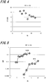
- FIG. 4 shows a change of signal to interference power ratio (SIR) due to increasing the number of terminals Nv, in the case where the number of antennas Nb of the base station is equal to one hundred.
- SIR signal to interference power ratio
- FIG. 5 shows the change of a bit error rate (BER) of a received signal with respect to the number of terminals Nv.
- the modulation system of the transmitting signal is 16 Quadrature Amplitude Modulation (16QAM) and Quadrature Phase Shift Keying (QPSK) modulation.
- the modulation system of transmitting signal is QPSK
- a BER ⁇ 10 -2 will be maintained with up to about 20 sets of terminals.
- BER ⁇ 10 -2 is the 3G (3rd generation) present mobile telephone system which used the Code Division Multiple Access (CDMA) communication system, and is the same as BER that needs to be maintained when performing an audio communication. This value, BER ⁇ 10 -2 , becomes a standard when judging the suitability of a communication system.
- CDMA Code Division Multiple Access
- the modulation of a multi-value higher than QPSK the condition of BER ⁇ 10 -2 is not satisfied for four or more sets of terminals. That is, up to three terminals, a BER ⁇ 10 -2 will be satisfied and communication with 16QAM system is attained. However, when the number of terminals are four or more sets, the condition of BER ⁇ 10 -2 is not satisfied and the system cannot communicate appropriately. In a data communication with a permissible BER of about BER ⁇ 10 -3 , about 12 sets of terminals by the QPSK system can simultaneously communicate. In the case of the 16QAM system with the same standard only about four sets of terminals can simultaneously communicate. Thus, in a massive MIMO communication system, the number of terminals which one base station can accommodate will be limited to several sets. When the number of terminals that the base station accommodates exceeds a limit, a data transfer rate is limited to a low speed.
- Zero forcing is a method for removing the interference of the transmitting signal completely.
- This method includes the step of conditioning the transmitting signal Tx by the correlation matrix (HxH*) -1 as a precode matrix as in Formula 1.
- the correlation matrix H ⁇ H* turns into a matrix of (Nv x Nv) about the terminal number Nv
- the computational complexity increases with the increase in a number of terminals.
- a computational period currently assumed with the massive MIMO communication system is about 500 ⁇ S; therefore, high speed calculations within that computational period is needed.
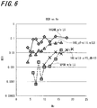
- FIG. 6 shows an example of the simulated communication processing explained so far according to an exemplary embodiment.
- the array antenna 110 of one base station is equipped with 100 antennas, and the BER of all the terminals is shown with increasing the number of terminals Nv in the cell.
- the characteristic response of "16QAM_w/0 LU” and the characteristic response of "QPSK w/o LU" are the same as shown in FIG. 5 .
- the curves differ in FIG. 5 and FIG. 6 due to the differing values of random numbers used at the time of simulation.
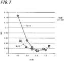
- FIG. 7 illustrates the n0 dependency on the BER.
- Nv 10 and 16.
- the method of determining ⁇ 0 is based on the following. For example, when 16QAM modulation is applied, all of the interference terms act as a noise. Therefore, an energy per bit to noise power spectral density ratio (EbN0), which obtains a desired BER, is selected as ⁇ 0 from the characteristic of BER with respect to the EbN0 of 16QAM, which is generally well known.
- EbN0 energy per bit to noise power spectral density ratio
- the BER deviates from the theoretical value greatly and no improvement of BER is observed. This is because the interference will be reduced when ⁇ 0 is made small, but the level of confidence of the received signal also deteriorates, as previously described.
- a diagonal matrix G which has the gain gi in a diagonal element, is given by Formula 15.
- G g 0 0 g 1 0 ⁇ ⁇
- the received signal from a base station since the received signal from a base station becomes a lower triangular matrix, it remains as a triangular matrix and the interference can be adjusted by the gain gi by multiplying by the diagonal matrix G in Formula 15. That is, by using U -1 xG as a precode matrix, the received signal is given by Formula 16.
- Formula 11 can be applied to the diagonal matrix G, and the interference can be controlled.
- an uplink signal is considered as the received signal by the base station transmitted by the mobile terminal and is represented by Formula 17.
- Rx H ⁇ Tx
- the triangular factorization of Formula 3 is applied to the uplink signal. That is, the inverse matrix L -1 of the lower triangular matrix L, is multiplied to the uplink signal as a post-code matrix, and is given by Formula 18.
- the interference of the uplink signal can be reduced in half by average, similar to the process of Formula 5.
- U is an upper triangular matrix and G is a diagonal matrix; therefore, Formula 19 results in an upper triangular matrix.
- the interference term is controlled by the diagonal matrix G, the interference can be reduced, as compared with the case where Formula 18 is applied alone.
- triangular decomposition is performed on a channel correlation matrix H ⁇ H*, and a transmission signal is multiplied by the inverse matrix of the upper triangular matrix thereof as a precode matrix.
- Each element U ij of the upper triangular matrix of the triangular matrix is multiplied by a gain gi, and an element L ij of the lower triangular matrix is multiplied by a gain 1/gi.
- the limitation of the number of terminals that can be accommodated is eased by setting inverse-matrix L -1 of the lower triangular matrix L as the precode matrix.
- interference can be reduced by half using an upper triangular matrix also during the uplink from a terminal to a base station, and therefore, interference can be further reduced by performing gain control at the time of transmission from a terminal.
Landscapes
- Engineering & Computer Science (AREA)
- Computer Networks & Wireless Communication (AREA)
- Signal Processing (AREA)
- Radio Transmission System (AREA)
- Mobile Radio Communication Systems (AREA)
Claims (8)
- Basisstation (100), die Folgendes umfasst:einen Datensteuerschaltkreis (101), der konfiguriert ist zum Verarbeiten eines Übertragungssignals, das gleichzeitig zu mehreren mobilen Endgeräten übertragen werden soll;einen Modulatorschaltkreis (102A ... 102Nv), der konfiguriert ist zum Modulieren des Übertragungssignals, das durch den Datensteuerschaltkreis verarbeitet wird;einen Hochfrequenzmodulatorschaltkreis (103A ... 103Nv), der konfiguriert ist zum Modulieren des Übertragungssignals, das durch den Modulatorschaltkreis moduliert wird, in ein Hochfrequenzübertragungssignal; undmehrere Antennen (111A ... 111Nb), die konfiguriert sind zum drahtlosen Übertragen des Hochfrequenzübertragungssignals zu den mehreren mobilen Endgeräten, wobei, wenn eine Anzahl der mehreren mobilen Endgeräte, zu denen das Übertragungssignal übertragen werden soll, Nv ist und eine Anzahl der mehreren Antennen Nb ist, der Datensteuerschaltkreis konfiguriert ist zum Multiplizieren des Übertragungssignals mit einer Vorcodierungsmatrix, wobei das Multiplizieren des Übertragungssignals mit der Vorcodierungsmatrix Folgendes umfasst:Erzeugen einer Kanalmatrix H, die gleich Nv × Nb ist;Dreiecksfaktorisieren einer Kanalkorrelationsmatrix H × H*, wobei * eine komplex konjugierte Transponierte repräsentiert, wodurch eine untere Dreiecksmatrix L erhalten wird;Erhalten einer neuen unteren Dreiecksmatrix Lnew durch Multiplizieren jedes Elements lij der unteren Dreiecksmatrix L mit 1/gi,wobei i ein Zeilenindex ist und j ein Spaltenindex ist und wobei gi eine Empfangsverstärkung ist, die mit dem i-ten mobilen Endgerät der Nv mobilen Endgeräte assoziiert ist,und Setzen der inversen Matrix Lnew -1 der neuen unteren Dreiecksmatrix Lnew als die Vorcodierungsmatrix.
- Basisstation nach Anspruch 1, wobei die Empfangsverstärkung gi festgelegt wird, eine Summe von Störungstermen lin/gn zu den mobilen Endgeräten zu enthalten, wobei n ein Spaltenindex ist, der von 0 zu i-1 läuft.
- Basisstation nach Anspruch 2, wobei, wenn die Summe von Störungstermen berechnet wird, ein störendes mobiles Endgerät zu einem spezifischen mobilen Endgerät beschränkt wird.
- Basisstation nach Anspruch 1, wobei eine Summe von Termen 1/gn, wobei n ein Index ist, der mit dem n-ten mobilen Endgerät assoziiert ist und von 0 zu Nv-1 läuft, als konstant gehalten wird, indem die Verstärkung gi des Übertragungssignals für jedes mobile Endgerät, das kein störendes mobiles Endgerät ist, verringert wird.
- Basisstation nach Anspruch 1, wobei der Datensteuerschaltkreis ferner konfiguriert ist zum Multiplizieren eines empfangenen Signals, das von den mobilen Endgeräten übertragen wird, mit einer Nachcodierungsmatrix, um eine Empfangsverarbeitung am empfangenen Signal, das von den mobilen Endgeräten übertragen wird, durchzuführen.
- Basisstation nach Anspruch 5, wobei der Datensteuerschaltkreis ferner zu Folgendem konfiguriert ist:
Dreiecksfaktorisieren der Kanalkorrelationsmatrix H × H*, um eine untere Dreiecksmatrix L zu erhalten, wobei die inverse Matrix L-1 der unteren Dreiecksmatrix L als die Nachcodierungsmatrix dient. - Basisstation nach Anspruch 5, wobei eine Verstärkung gi, die zu jedem mobilen Endgerät bereitgestellt wird, zum Bilden einer Diagonalmatrix G verwendet wird, die als die Nachcodierungsmatrix dient.
- Basisstation nach Anspruch 1, wobei die Basisstation über einen Basisstationssteuerschaltkreis mit einem externen Netzwerk verbunden ist.
Applications Claiming Priority (1)
| Application Number | Priority Date | Filing Date | Title |
|---|---|---|---|
| US201462041408P | 2014-08-25 | 2014-08-25 |
Publications (2)
| Publication Number | Publication Date |
|---|---|
| EP2991237A1 EP2991237A1 (de) | 2016-03-02 |
| EP2991237B1 true EP2991237B1 (de) | 2018-05-23 |
Family
ID=53969293
Family Applications (1)
| Application Number | Title | Priority Date | Filing Date |
|---|---|---|---|
| EP15182233.5A Not-in-force EP2991237B1 (de) | 2014-08-25 | 2015-08-24 | Basis station und massives mimo-kommunikationsverfahren |
Country Status (3)
| Country | Link |
|---|---|
| US (1) | US9716534B2 (de) |
| EP (1) | EP2991237B1 (de) |
| CN (1) | CN105391480A (de) |
Families Citing this family (2)
| Publication number | Priority date | Publication date | Assignee | Title |
|---|---|---|---|---|
| TWI817231B (zh) * | 2020-11-10 | 2023-10-01 | 鴻齡科技股份有限公司 | 雲無線接入網路中上行訊號處理方法及系統 |
| US11791871B2 (en) * | 2020-12-21 | 2023-10-17 | Nvidia Corporation | Parallel precoding for downlink transmission |
Family Cites Families (7)
| Publication number | Priority date | Publication date | Assignee | Title |
|---|---|---|---|---|
| DE10333514B4 (de) * | 2003-07-17 | 2005-10-13 | Siemens Ag | Nichtlineares Vorcodierungsverfahren für einen digitalen Broadcastkanal |
| WO2008060105A1 (en) | 2006-11-15 | 2008-05-22 | Lg Electronics Inc. | Data transmission method using dirty paper coding in mimo system |
| US7778598B2 (en) * | 2007-01-22 | 2010-08-17 | Mitsubishi Electric Research Laboratories, Inc. | Asymmetric cooperation in downlink cellular networks with relay stations |
| US8761288B2 (en) * | 2008-02-26 | 2014-06-24 | Nxp, B.V. | Limited channel information feedback error-free channel vector quantization scheme for precoding MU-MIMO |
| CN101247208B (zh) * | 2008-02-29 | 2013-05-08 | 中兴通讯股份有限公司 | 一种下行多用户联合空分复用信号的发送及收发方法 |
| US9130629B2 (en) * | 2011-03-04 | 2015-09-08 | Sharp Kabushiki Kaisha | Wireless communication system, base station device, and terminal device |
| CN110460361B (zh) * | 2013-05-10 | 2020-06-19 | 华为技术有限公司 | 确定预编码矩阵指示的方法、用户设备和基站 |
-
2015
- 2015-08-24 US US14/834,031 patent/US9716534B2/en not_active Expired - Fee Related
- 2015-08-24 EP EP15182233.5A patent/EP2991237B1/de not_active Not-in-force
- 2015-08-25 CN CN201510526514.5A patent/CN105391480A/zh active Pending
Non-Patent Citations (1)
| Title |
|---|
| None * |
Also Published As
| Publication number | Publication date |
|---|---|
| CN105391480A (zh) | 2016-03-09 |
| US20160056867A1 (en) | 2016-02-25 |
| EP2991237A1 (de) | 2016-03-02 |
| US9716534B2 (en) | 2017-07-25 |
Similar Documents
| Publication | Publication Date | Title |
|---|---|---|
| Nayebi et al. | Precoding and power optimization in cell-free massive MIMO systems | |
| EP2786508B1 (de) | Verfahren und vorrichtung zum dekodieren in kommunikationssystemen mit korrelierten signalen und interferenzen. | |
| EP1742405B1 (de) | Verfahren zur Kanalschätzung mit Raummultiplexierung in einem orthogonalen Frequenzmultiplexsystem mit mehreren Antennen | |
| You et al. | Pilot reuse for massive MIMO transmission over spatially correlated Rayleigh fading channels | |
| EP3714550B1 (de) | Verfahren, systeme und einheiten eines verteilten basisstationssystems zur behandlung von downlink-kommunikation | |
| CN107483088B (zh) | 大规模mimo鲁棒预编码传输方法 | |
| JP5738581B2 (ja) | 無線通信システムにおけるマルチユーザmimoの伝送方法および基地局 | |
| CN101682475B (zh) | 用于控制无线通信网络中的多天线传输的方法和设备 | |
| CN111034063A (zh) | 通信方法、通信装置和系统 | |
| US20140369311A1 (en) | Method, Terminal And Base Station For Multi-User Interference Suppression | |
| EP3407507B1 (de) | Signalübertragungsverfahren eines drahtloskommunikationssystems, basisstation und benutzergerät | |
| CN111713054A (zh) | 通信方法、通信装置和系统 | |
| EP3461039B1 (de) | Übertragungsvorrichtung, kommunikationssystem und vorcodierendes berechnungsverfahren | |
| JP5340634B2 (ja) | 無線通信装置及び無線通信方法 | |
| EP2727304B1 (de) | Rauschbestimmungsfilter | |
| CN105471485A (zh) | 用于发送和接收码本子集限制位图的方法和设备 | |
| US20140254495A1 (en) | Systems and methods for reducing complexity in modulation coding scheme (mcs) adaptation | |
| Saatlou et al. | Spectral efficiency maximization of a single cell massive MU-MIMO down-link TDD system by appropriate resource allocation | |
| EP2557720B1 (de) | Transformationsvorrichtung und verfahren | |
| EP2991237B1 (de) | Basis station und massives mimo-kommunikationsverfahren | |
| Bogale et al. | Pilot contamination mitigation for wideband massive MIMO systems | |
| Bogale et al. | Pilot contamination mitigation for wideband massive MMO: Number of cells vs multipath | |
| US9680550B2 (en) | Method and apparatus for transmitting feedback about channel having spatial correlation | |
| CN116235415B (zh) | 信号传输方法及相关装置 | |
| WO2022226852A1 (en) | Method, apparatus, and system for measuring a mimo channel |
Legal Events
| Date | Code | Title | Description |
|---|---|---|---|
| PUAI | Public reference made under article 153(3) epc to a published international application that has entered the european phase |
Free format text: ORIGINAL CODE: 0009012 |
|
| 17P | Request for examination filed |
Effective date: 20150924 |
|
| AK | Designated contracting states |
Kind code of ref document: A1 Designated state(s): AL AT BE BG CH CY CZ DE DK EE ES FI FR GB GR HR HU IE IS IT LI LT LU LV MC MK MT NL NO PL PT RO RS SE SI SK SM TR |
|
| AX | Request for extension of the european patent |
Extension state: BA ME |
|
| STAA | Information on the status of an ep patent application or granted ep patent |
Free format text: STATUS: EXAMINATION IS IN PROGRESS |
|
| 17Q | First examination report despatched |
Effective date: 20170223 |
|
| GRAP | Despatch of communication of intention to grant a patent |
Free format text: ORIGINAL CODE: EPIDOSNIGR1 |
|
| STAA | Information on the status of an ep patent application or granted ep patent |
Free format text: STATUS: GRANT OF PATENT IS INTENDED |
|
| INTG | Intention to grant announced |
Effective date: 20171121 |
|
| RAP1 | Party data changed (applicant data changed or rights of an application transferred) |
Owner name: SONY MOBILE COMMUNICATIONS INC. Owner name: SONY CORPORATION |
|
| GRAJ | Information related to disapproval of communication of intention to grant by the applicant or resumption of examination proceedings by the epo deleted |
Free format text: ORIGINAL CODE: EPIDOSDIGR1 |
|
| STAA | Information on the status of an ep patent application or granted ep patent |
Free format text: STATUS: EXAMINATION IS IN PROGRESS |
|
| GRAR | Information related to intention to grant a patent recorded |
Free format text: ORIGINAL CODE: EPIDOSNIGR71 |
|
| GRAS | Grant fee paid |
Free format text: ORIGINAL CODE: EPIDOSNIGR3 |
|
| STAA | Information on the status of an ep patent application or granted ep patent |
Free format text: STATUS: GRANT OF PATENT IS INTENDED |
|
| GRAA | (expected) grant |
Free format text: ORIGINAL CODE: 0009210 |
|
| STAA | Information on the status of an ep patent application or granted ep patent |
Free format text: STATUS: THE PATENT HAS BEEN GRANTED |
|
| INTC | Intention to grant announced (deleted) | ||
| INTG | Intention to grant announced |
Effective date: 20180412 |
|
| AK | Designated contracting states |
Kind code of ref document: B1 Designated state(s): AL AT BE BG CH CY CZ DE DK EE ES FI FR GB GR HR HU IE IS IT LI LT LU LV MC MK MT NL NO PL PT RO RS SE SI SK SM TR |
|
| REG | Reference to a national code |
Ref country code: GB Ref legal event code: FG4D |
|
| REG | Reference to a national code |
Ref country code: CH Ref legal event code: EP |
|
| REG | Reference to a national code |
Ref country code: IE Ref legal event code: FG4D |
|
| REG | Reference to a national code |
Ref country code: AT Ref legal event code: REF Ref document number: 1002350 Country of ref document: AT Kind code of ref document: T Effective date: 20180615 |
|
| REG | Reference to a national code |
Ref country code: DE Ref legal event code: R096 Ref document number: 602015011363 Country of ref document: DE |
|
| REG | Reference to a national code |
Ref country code: NL Ref legal event code: MP Effective date: 20180523 |
|
| REG | Reference to a national code |
Ref country code: LT Ref legal event code: MG4D |
|
| PG25 | Lapsed in a contracting state [announced via postgrant information from national office to epo] |
Ref country code: ES Free format text: LAPSE BECAUSE OF FAILURE TO SUBMIT A TRANSLATION OF THE DESCRIPTION OR TO PAY THE FEE WITHIN THE PRESCRIBED TIME-LIMIT Effective date: 20180523 Ref country code: SE Free format text: LAPSE BECAUSE OF FAILURE TO SUBMIT A TRANSLATION OF THE DESCRIPTION OR TO PAY THE FEE WITHIN THE PRESCRIBED TIME-LIMIT Effective date: 20180523 Ref country code: NO Free format text: LAPSE BECAUSE OF FAILURE TO SUBMIT A TRANSLATION OF THE DESCRIPTION OR TO PAY THE FEE WITHIN THE PRESCRIBED TIME-LIMIT Effective date: 20180823 Ref country code: FI Free format text: LAPSE BECAUSE OF FAILURE TO SUBMIT A TRANSLATION OF THE DESCRIPTION OR TO PAY THE FEE WITHIN THE PRESCRIBED TIME-LIMIT Effective date: 20180523 Ref country code: LT Free format text: LAPSE BECAUSE OF FAILURE TO SUBMIT A TRANSLATION OF THE DESCRIPTION OR TO PAY THE FEE WITHIN THE PRESCRIBED TIME-LIMIT Effective date: 20180523 Ref country code: BG Free format text: LAPSE BECAUSE OF FAILURE TO SUBMIT A TRANSLATION OF THE DESCRIPTION OR TO PAY THE FEE WITHIN THE PRESCRIBED TIME-LIMIT Effective date: 20180823 |
|
| PG25 | Lapsed in a contracting state [announced via postgrant information from national office to epo] |
Ref country code: GR Free format text: LAPSE BECAUSE OF FAILURE TO SUBMIT A TRANSLATION OF THE DESCRIPTION OR TO PAY THE FEE WITHIN THE PRESCRIBED TIME-LIMIT Effective date: 20180824 Ref country code: RS Free format text: LAPSE BECAUSE OF FAILURE TO SUBMIT A TRANSLATION OF THE DESCRIPTION OR TO PAY THE FEE WITHIN THE PRESCRIBED TIME-LIMIT Effective date: 20180523 Ref country code: LV Free format text: LAPSE BECAUSE OF FAILURE TO SUBMIT A TRANSLATION OF THE DESCRIPTION OR TO PAY THE FEE WITHIN THE PRESCRIBED TIME-LIMIT Effective date: 20180523 Ref country code: NL Free format text: LAPSE BECAUSE OF FAILURE TO SUBMIT A TRANSLATION OF THE DESCRIPTION OR TO PAY THE FEE WITHIN THE PRESCRIBED TIME-LIMIT Effective date: 20180523 Ref country code: HR Free format text: LAPSE BECAUSE OF FAILURE TO SUBMIT A TRANSLATION OF THE DESCRIPTION OR TO PAY THE FEE WITHIN THE PRESCRIBED TIME-LIMIT Effective date: 20180523 |
|
| REG | Reference to a national code |
Ref country code: AT Ref legal event code: MK05 Ref document number: 1002350 Country of ref document: AT Kind code of ref document: T Effective date: 20180523 |
|
| PG25 | Lapsed in a contracting state [announced via postgrant information from national office to epo] |
Ref country code: CZ Free format text: LAPSE BECAUSE OF FAILURE TO SUBMIT A TRANSLATION OF THE DESCRIPTION OR TO PAY THE FEE WITHIN THE PRESCRIBED TIME-LIMIT Effective date: 20180523 Ref country code: SK Free format text: LAPSE BECAUSE OF FAILURE TO SUBMIT A TRANSLATION OF THE DESCRIPTION OR TO PAY THE FEE WITHIN THE PRESCRIBED TIME-LIMIT Effective date: 20180523 Ref country code: DK Free format text: LAPSE BECAUSE OF FAILURE TO SUBMIT A TRANSLATION OF THE DESCRIPTION OR TO PAY THE FEE WITHIN THE PRESCRIBED TIME-LIMIT Effective date: 20180523 Ref country code: PL Free format text: LAPSE BECAUSE OF FAILURE TO SUBMIT A TRANSLATION OF THE DESCRIPTION OR TO PAY THE FEE WITHIN THE PRESCRIBED TIME-LIMIT Effective date: 20180523 Ref country code: EE Free format text: LAPSE BECAUSE OF FAILURE TO SUBMIT A TRANSLATION OF THE DESCRIPTION OR TO PAY THE FEE WITHIN THE PRESCRIBED TIME-LIMIT Effective date: 20180523 Ref country code: AT Free format text: LAPSE BECAUSE OF FAILURE TO SUBMIT A TRANSLATION OF THE DESCRIPTION OR TO PAY THE FEE WITHIN THE PRESCRIBED TIME-LIMIT Effective date: 20180523 Ref country code: RO Free format text: LAPSE BECAUSE OF FAILURE TO SUBMIT A TRANSLATION OF THE DESCRIPTION OR TO PAY THE FEE WITHIN THE PRESCRIBED TIME-LIMIT Effective date: 20180523 |
|
| REG | Reference to a national code |
Ref country code: DE Ref legal event code: R097 Ref document number: 602015011363 Country of ref document: DE |
|
| PG25 | Lapsed in a contracting state [announced via postgrant information from national office to epo] |
Ref country code: IT Free format text: LAPSE BECAUSE OF FAILURE TO SUBMIT A TRANSLATION OF THE DESCRIPTION OR TO PAY THE FEE WITHIN THE PRESCRIBED TIME-LIMIT Effective date: 20180523 Ref country code: SM Free format text: LAPSE BECAUSE OF FAILURE TO SUBMIT A TRANSLATION OF THE DESCRIPTION OR TO PAY THE FEE WITHIN THE PRESCRIBED TIME-LIMIT Effective date: 20180523 |
|
| PG25 | Lapsed in a contracting state [announced via postgrant information from national office to epo] |
Ref country code: MC Free format text: LAPSE BECAUSE OF FAILURE TO SUBMIT A TRANSLATION OF THE DESCRIPTION OR TO PAY THE FEE WITHIN THE PRESCRIBED TIME-LIMIT Effective date: 20180523 |
|
| PLBE | No opposition filed within time limit |
Free format text: ORIGINAL CODE: 0009261 |
|
| REG | Reference to a national code |
Ref country code: CH Ref legal event code: PL |
|
| STAA | Information on the status of an ep patent application or granted ep patent |
Free format text: STATUS: NO OPPOSITION FILED WITHIN TIME LIMIT |
|
| PG25 | Lapsed in a contracting state [announced via postgrant information from national office to epo] |
Ref country code: CH Free format text: LAPSE BECAUSE OF NON-PAYMENT OF DUE FEES Effective date: 20180831 Ref country code: LU Free format text: LAPSE BECAUSE OF NON-PAYMENT OF DUE FEES Effective date: 20180824 Ref country code: LI Free format text: LAPSE BECAUSE OF NON-PAYMENT OF DUE FEES Effective date: 20180831 |
|
| 26N | No opposition filed |
Effective date: 20190226 |
|
| REG | Reference to a national code |
Ref country code: BE Ref legal event code: MM Effective date: 20180831 |
|
| PG25 | Lapsed in a contracting state [announced via postgrant information from national office to epo] |
Ref country code: SI Free format text: LAPSE BECAUSE OF FAILURE TO SUBMIT A TRANSLATION OF THE DESCRIPTION OR TO PAY THE FEE WITHIN THE PRESCRIBED TIME-LIMIT Effective date: 20180523 |
|
| PG25 | Lapsed in a contracting state [announced via postgrant information from national office to epo] |
Ref country code: BE Free format text: LAPSE BECAUSE OF NON-PAYMENT OF DUE FEES Effective date: 20180831 Ref country code: FR Free format text: LAPSE BECAUSE OF NON-PAYMENT OF DUE FEES Effective date: 20180831 |
|
| PGFP | Annual fee paid to national office [announced via postgrant information from national office to epo] |
Ref country code: DE Payment date: 20190813 Year of fee payment: 5 |
|
| PG25 | Lapsed in a contracting state [announced via postgrant information from national office to epo] |
Ref country code: AL Free format text: LAPSE BECAUSE OF FAILURE TO SUBMIT A TRANSLATION OF THE DESCRIPTION OR TO PAY THE FEE WITHIN THE PRESCRIBED TIME-LIMIT Effective date: 20180523 |
|
| PG25 | Lapsed in a contracting state [announced via postgrant information from national office to epo] |
Ref country code: MT Free format text: LAPSE BECAUSE OF NON-PAYMENT OF DUE FEES Effective date: 20180824 |
|
| PG25 | Lapsed in a contracting state [announced via postgrant information from national office to epo] |
Ref country code: TR Free format text: LAPSE BECAUSE OF FAILURE TO SUBMIT A TRANSLATION OF THE DESCRIPTION OR TO PAY THE FEE WITHIN THE PRESCRIBED TIME-LIMIT Effective date: 20180523 |
|
| GBPC | Gb: european patent ceased through non-payment of renewal fee |
Effective date: 20190824 |
|
| PG25 | Lapsed in a contracting state [announced via postgrant information from national office to epo] |
Ref country code: PT Free format text: LAPSE BECAUSE OF FAILURE TO SUBMIT A TRANSLATION OF THE DESCRIPTION OR TO PAY THE FEE WITHIN THE PRESCRIBED TIME-LIMIT Effective date: 20180523 |
|
| PG25 | Lapsed in a contracting state [announced via postgrant information from national office to epo] |
Ref country code: IE Free format text: LAPSE BECAUSE OF NON-PAYMENT OF DUE FEES Effective date: 20180824 Ref country code: CY Free format text: LAPSE BECAUSE OF FAILURE TO SUBMIT A TRANSLATION OF THE DESCRIPTION OR TO PAY THE FEE WITHIN THE PRESCRIBED TIME-LIMIT Effective date: 20180523 Ref country code: HU Free format text: LAPSE BECAUSE OF FAILURE TO SUBMIT A TRANSLATION OF THE DESCRIPTION OR TO PAY THE FEE WITHIN THE PRESCRIBED TIME-LIMIT; INVALID AB INITIO Effective date: 20150824 Ref country code: MK Free format text: LAPSE BECAUSE OF NON-PAYMENT OF DUE FEES Effective date: 20180523 |
|
| PG25 | Lapsed in a contracting state [announced via postgrant information from national office to epo] |
Ref country code: IS Free format text: LAPSE BECAUSE OF FAILURE TO SUBMIT A TRANSLATION OF THE DESCRIPTION OR TO PAY THE FEE WITHIN THE PRESCRIBED TIME-LIMIT Effective date: 20180923 |
|
| PG25 | Lapsed in a contracting state [announced via postgrant information from national office to epo] |
Ref country code: GB Free format text: LAPSE BECAUSE OF NON-PAYMENT OF DUE FEES Effective date: 20190824 |
|
| REG | Reference to a national code |
Ref country code: DE Ref legal event code: R119 Ref document number: 602015011363 Country of ref document: DE |
|
| PG25 | Lapsed in a contracting state [announced via postgrant information from national office to epo] |
Ref country code: DE Free format text: LAPSE BECAUSE OF NON-PAYMENT OF DUE FEES Effective date: 20210302 |