EP2991177B1 - Überspannungsschutzeinrichtung - Google Patents
Überspannungsschutzeinrichtung Download PDFInfo
- Publication number
- EP2991177B1 EP2991177B1 EP15181971.1A EP15181971A EP2991177B1 EP 2991177 B1 EP2991177 B1 EP 2991177B1 EP 15181971 A EP15181971 A EP 15181971A EP 2991177 B1 EP2991177 B1 EP 2991177B1
- Authority
- EP
- European Patent Office
- Prior art keywords
- overvoltage protection
- protection device
- terminal blocks
- overvoltage
- terminal
- Prior art date
- Legal status (The legal status is an assumption and is not a legal conclusion. Google has not performed a legal analysis and makes no representation as to the accuracy of the status listed.)
- Active
Links
Images


Classifications
-
- H—ELECTRICITY
- H01—ELECTRIC ELEMENTS
- H01T—SPARK GAPS; OVERVOLTAGE ARRESTERS USING SPARK GAPS; SPARKING PLUGS; CORONA DEVICES; GENERATING IONS TO BE INTRODUCED INTO NON-ENCLOSED GASES
- H01T4/00—Overvoltage arresters using spark gaps
- H01T4/06—Mounting arrangements for a plurality of overvoltage arresters
Definitions
- the invention relates to an overvoltage protection device for signal and control lines, in particular for a signaling device, for arrangement between an outdoor system and an indoor system, with at least two terminal blocks, which are each part of a signal path, the terminal blocks connecting contacts for connection to the indoor and outdoor system have, a base terminal with a connection for a discharge to earth, and at least one overvoltage protection device electrically connected to the terminal blocks, a connector housing being provided in which the overvoltage protection device is installed.
- Such a surge protection device is known, for example, from Phoenix Contact "Network & Signal Quality TRABTECH PLUGTRAB PT-IQ Intelligent Surge Protection with System", 2013.
- Railway engineering systems include a variety of electricity-operated elements of outdoor facilities, e.g. Railway signals or switches, which are connected via lines (signal paths) to an indoor system (e.g. a signal box or the control electronics of the signal box).
- the bodies of the outdoor facilities are generally grounded, however, overvoltage can enter the control and switching elements (e.g. interlocking system), for example due to inductive coupling or potential differences caused by voltage funnels, e.g. caused by remote lightning strikes, which can lead to damage and breakdowns.
- a disadvantage of this arrangement is that the overvoltage protection device takes up a lot of space in addition to the isolating measuring terminal block and the derivation takes place over a relatively long distance, which is associated with high leakage inductances, so that large interference fields are induced during discharge and a higher voltage at the discharge line to earth in If there is an overvoltage.
- DE 20 2011 002 019 U1 discloses an arrangement for opening a line connection within a base part, which is provided for receiving a surge arrester plug-in part, an uninterruptible switch contact being provided in the base part for at least one line connection and being operable by a mechanical element of the plug-in part.
- the arrangement comprises an adapter for receiving the surge arrester plug-in part intended for use in the base part in order to park this plug-in part, a means being formed on a foot part of the adapter which opens the switch contact or contacts in the base part.
- the freedom from interference during operation and the signaling safety of the system should be ensured and at the same time the distance between discharge paths should be kept small.
- the terminal blocks and the base terminal each have a slot for plugging in the plug housing of the surge protection device, the terminal blocks each having a captive separating knife (e.g. pivotable) for temporarily separating the signal paths.
- a captive separating knife e.g. pivotable
- the overvoltage protection device While in the state of the art the overvoltage protection device is plugged onto a separate base and connected to the isolating measurement terminal block by cable, in the overvoltage protection device according to the invention the isolating measurement terminal blocks (modular terminals with isolating knife) are equipped with a slot on which the overvoltage protection device can be attached.
- Surge protection implemented by plugging the surge protective devices directly onto the isolating measuring series and basic terminals.
- the connections for single wires of the signaling device are connected to the terminal blocks and the earth connections to the base terminals.
- the base terminals are preferably equipped with discharge feet, which allow gas-tight and current-carrying contact to a mounting rail, eg DIN-Rail mounting rail TS 35, on which the terminal blocks can be mounted.
- isolating measuring series terminals are used as a link, e.g. between indoor and outdoor wiring.
- the terminal blocks to be used for the overvoltage protection device according to the invention must therefore be dimensioned so that the overvoltage protection device can be plugged on without covering the connection contacts for connection to the indoor and outdoor system.
- the connector housing and slot must be designed so that the surge protective devices can be connected in a shockproof and vibration-proof manner in accordance with EN 50125-3, this applies in particular to the area outside the tracks defined in accordance with EN 50125-3 (distance 1-3m from the track).
- connection contacts of the terminal blocks are connections for single wires.
- multi-wire cables can be used, but these are then connected as a single wire.
- the concept according to the invention takes into account that wires of different circuits can be connected to the same surge protection device. This is particularly important for signaling systems, since this special property ensures that there is no interference with the safety-relevant elements of signaling.
- the installation components used terminal block, base terminal
- the Surge protection devices must be approved for use in control and safety systems.
- the overvoltage protection device With the overvoltage protection device according to the invention, damage and malfunctions in signal boxes can be avoided, e.g. overvoltages in the cabling to the outdoor facilities, caused by remote lightning strikes.
- the surge protection device can be installed in a space-saving manner. It is also advantageous that the plug-in connection according to the invention between the terminal block and the surge protection device leads to the derivation and the signal execution at the same location, i.e. without a line connection between the terminal block or the base terminal block and the surge protection device, so that the overvoltage to be dissipated can be discharged to earth with the least possible leakage inductance. Due to the short discharge paths, there is less influence, in particular by magnetic fields on surrounding components.
- the surge protection device according to the invention can also be used in systems other than railway systems, in particular in systems which are not grounded, since the surge protection device according to the invention is constructed in an insulated manner and the active parts it contains cannot be touched.
- the overvoltage protection device according to the invention preferably corresponds at least to the requirements for protection type IP 20.
- the overvoltage protection device according to the invention is particularly suitable for protecting circuits in which the absence of interference is absolutely essential for operation.
- the surge protection device enables a time-delayed installation of various surge protection devices. This means that terminal blocks and base terminals can be preinstalled so that the system can be started up without overvoltage protection and retrofitting is possible later.
- the surge protection device comprises at least two discharge paths, each discharge path being a series connection of a surge arrester and a varistor.
- the invention therefore provides independent discharge elements.
- a gas arrester can serve as a surge arrester, for example.
- the combination of varistor and surge arrester can ensure that the signaling equipment does not have any repercussions during operation.
- the aging of the components is minimized in normal operation by preventing leakage currents.
- signal circuits and inputs / outputs that carry AC or DC voltages can be protected.
- the combination of varistor and surge arrester in series connection prevents the follow current.
- a barrier device is arranged between the discharge paths.
- the barrier device is intended to prevent the discharge paths from touching each other, and thus results in a captive separation between the two discharge paths. This enables the connection of various circuits to an overvoltage protection device, ensuring freedom from interference with the operation and the signaling safety of the system, while at the same time keeping the distance between the discharge paths small.
- the barrier device prevents the accidental contact of the components of the discharge paths and is preferably designed in the form of an insulating plate made of a suitable electrically insulating material.
- the dielectric strength of the barrier device is preferably> 10 kV / mm after aging.
- the required dielectric strength between the two discharge paths according to EN 50124-1 is ensured by appropriate dimensioning of the air and creepage distances.
- several field elements can be connected via the same surge protection device. This is particularly advantageous when three-wire field elements (e.g. a double filament lamp) are to be connected to surge protection devices, each of which has two discharge paths, since the remaining discharge path does not then have to remain free, as is the case with the surge protection device known from the prior art but for a different field element can be used.
- the planning and testing effort can be reduced.
- the terminal blocks preferably each have a test socket on the connections for the input and output lines for making contact with the signal path, in particular for measurement and test purposes.
- the test sockets are preferably on both sides (for indoor and outdoor systems) e.g. be provided for permanent contacting of a measuring device.
- a plurality of surge protection devices are present, each of which has a plug housing, and the arrangement of the terminal blocks has a plurality of slots for plugging the plug housing with the surge protection devices.
- the connector housing is preferably at least partially transparent, in particular in the region of the varistor. In this way, the surge protective devices can be checked by visual inspection. Thermal overloads can be detected.
- a monitoring device in particular an optical detection device, is provided for detecting overvoltage events within the overvoltage protection device. Monitoring by means of the monitoring device enables targeted maintenance and thereby improves the availability of the device.
- the overvoltage protection device can preferably be monitored remotely.
- the monitoring device can be equipped with a memory which can store a plurality of surge discharge events. A separate monitoring device can also be provided for each surge protection device. Monitoring the surge protective devices is particularly advantageous for decentralized signaling devices.
- Fig. 1 shows a railway system with a signal box 1 (indoor system) and a train signal 2 (outdoor system), which is controlled by control electronics 3 of the signal box 1.
- the signal box 1 is equipped with an external lightning protection 4 , which is grounded via a foundation ring electrode 5 .
- a main equipotential bonding 6 and internal surge protection devices 7 serve to protect the signal box 1 against direct lightning strikes.
- the signal box 1 is equipped with an additional one Surge protection device 9 equipped according to the present invention.
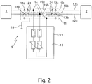
- Fig. 2 shows the structure of the surge protection device 9 according to the invention.
- Two terminal blocks 10a, 10b and a base terminal 11 are used to connect the external system 2 to the internal system 1, the terminal blocks 10a, 10b each forming part of a signal path 12a, 12b .
- the order in which the clamps (10a, 10b, 11) are arranged is arbitrary.
- the terminal blocks 10a, 10b are equipped with connection contacts 13a, 13b, 14a, 14b (single wire connections) for connection to the indoor or outdoor system 1, 2.
- the base clamp 11 has a diverter foot 15 for the earth discharge.
- An overvoltage protection device 17 is connected to the terminal blocks 10a, 10b and the base terminal 11 via plug contacts.
- the terminals 10a, 10b, 11 have slots 16 .
- the overvoltage protection device 17 is arranged in a plug housing 23 which can be plugged onto the terminals 10a, 10b, 11 via the slots 16 and can thus be electrically and mechanically contacted.
- Each signal path 12a, 12b is connected to earth via the overvoltage protection device.
- the terminal blocks 10a, 10b each have a, preferably pivotable, separating knife 19a, 19b for temporarily separating the signal paths.
- test sockets 24 are provided, by means of which a test device or measuring device can be contacted with the signal paths 12a, 12b.
- Fig. 3 shows a perspective view of an overvoltage protection device 9 according to the invention with two attached overvoltage protection devices 17.
- the overvoltage protection device 9 according to the invention can include a large number of overvoltage protection devices 17.
- the Surge protective devices 17 are arranged on a mounting rail 22 , which is in turn placed on an insulating base plate (conductor guide plate - not shown), in particular when used in non-earthed areas.
- the earth contact can be implemented via the mounting rail 22.
- a display module can be provided at the lower end of the mounting rail, for example, to display discharge events.
- the overvoltage protection device 17 comprises two discharge paths 18a, 18b, which can be connected to the signal paths 12a, 12b via connections 21a, 21b.
- the two connections 21a, 21b are at a distance d 1 from one another, the distance d 1 designating the creepage and clearance distance to be maintained between the connections 21a, 21b of the two discharge paths 18a, 18b of the overvoltage protection device 17.
- a surge arrester 19 and a varistor 20 are connected in series in the discharge paths 18a, 18b.
- the order in which varistor 19 and surge arrester 20 are arranged is arbitrary, but they are always in series.
- a barrier device 21 is arranged between the two discharge paths 18a, 18b, so that the discharge paths 18a, 18b are electrically insulated from one another.
- the overvoltage protection device provides that the overvoltage protection devices are plugged directly onto an isolating measuring terminal block, as a result of which a space-saving, easy-to-use and low-interference overvoltage protection device is realized.
Landscapes
- Emergency Protection Circuit Devices (AREA)
Priority Applications (2)
| Application Number | Priority Date | Filing Date | Title |
|---|---|---|---|
| PL15181971T PL2991177T3 (pl) | 2014-09-01 | 2015-08-21 | Urządzenie ochrony przepięciowej |
| HRP20201168TT HRP20201168T1 (hr) | 2014-09-01 | 2020-07-27 | Uređaj za zaštitu od prenapona |
Applications Claiming Priority (1)
| Application Number | Priority Date | Filing Date | Title |
|---|---|---|---|
| DE102014217446.5A DE102014217446B4 (de) | 2014-09-01 | 2014-09-01 | Überspannungsschutzeinrichtung und Verwendung davon bei signaltechnischen Einrichtungen im Bahnbetrieb. |
Publications (2)
| Publication Number | Publication Date |
|---|---|
| EP2991177A1 EP2991177A1 (de) | 2016-03-02 |
| EP2991177B1 true EP2991177B1 (de) | 2020-05-13 |
Family
ID=53969233
Family Applications (1)
| Application Number | Title | Priority Date | Filing Date |
|---|---|---|---|
| EP15181971.1A Active EP2991177B1 (de) | 2014-09-01 | 2015-08-21 | Überspannungsschutzeinrichtung |
Country Status (8)
| Country | Link |
|---|---|
| EP (1) | EP2991177B1 (pl) |
| AU (1) | AU2015221437B2 (pl) |
| DE (1) | DE102014217446B4 (pl) |
| DK (1) | DK2991177T3 (pl) |
| ES (1) | ES2810758T3 (pl) |
| HR (1) | HRP20201168T1 (pl) |
| PL (1) | PL2991177T3 (pl) |
| PT (1) | PT2991177T (pl) |
Families Citing this family (2)
| Publication number | Priority date | Publication date | Assignee | Title |
|---|---|---|---|---|
| DE102018201333A1 (de) | 2018-01-29 | 2019-08-01 | Phoenix Contact Gmbh & Co. Kg | Überspannungsschutzensemble |
| DE202018100482U1 (de) | 2018-01-29 | 2018-03-09 | Phoenix Contact Gmbh & Co. Kg | Überspannungsschutzensemble |
Citations (2)
| Publication number | Priority date | Publication date | Assignee | Title |
|---|---|---|---|---|
| DE3831935A1 (de) * | 1988-09-20 | 1990-03-29 | Dehn & Soehne | Ueberspannungsschutz |
| DE102010012684A1 (de) * | 2010-03-24 | 2011-09-29 | Phoenix Contact Gmbh & Co. Kg | Überspannungsschutzgerät |
Family Cites Families (4)
| Publication number | Priority date | Publication date | Assignee | Title |
|---|---|---|---|---|
| DE19545505C1 (de) * | 1995-12-06 | 1997-05-28 | Dehn & Soehne | Überspannungsableiter |
| DE19856939A1 (de) * | 1998-12-10 | 2000-06-15 | Bettermann Obo Gmbh & Co Kg | Schaltungsanordnung zum Schutz von elektrischen Installationen gegen Überspannungsereignisse |
| WO2012047383A2 (en) * | 2010-09-30 | 2012-04-12 | Phoenix Contact Development & Manufacturing, Inc. | Terminal block for surge protection having integral disconnect |
| DE202011002019U1 (de) * | 2010-12-17 | 2011-04-07 | Dehn + Söhne Gmbh + Co. Kg | Anordnung zum Öffnen einer Leitungsverbindung |
-
2014
- 2014-09-01 DE DE102014217446.5A patent/DE102014217446B4/de not_active Withdrawn - After Issue
-
2015
- 2015-08-21 EP EP15181971.1A patent/EP2991177B1/de active Active
- 2015-08-21 PT PT151819711T patent/PT2991177T/pt unknown
- 2015-08-21 DK DK15181971.1T patent/DK2991177T3/da active
- 2015-08-21 PL PL15181971T patent/PL2991177T3/pl unknown
- 2015-08-21 ES ES15181971T patent/ES2810758T3/es active Active
- 2015-08-31 AU AU2015221437A patent/AU2015221437B2/en active Active
-
2020
- 2020-07-27 HR HRP20201168TT patent/HRP20201168T1/hr unknown
Patent Citations (2)
| Publication number | Priority date | Publication date | Assignee | Title |
|---|---|---|---|---|
| DE3831935A1 (de) * | 1988-09-20 | 1990-03-29 | Dehn & Soehne | Ueberspannungsschutz |
| DE102010012684A1 (de) * | 2010-03-24 | 2011-09-29 | Phoenix Contact Gmbh & Co. Kg | Überspannungsschutzgerät |
Also Published As
| Publication number | Publication date |
|---|---|
| DK2991177T3 (da) | 2020-08-10 |
| PL2991177T3 (pl) | 2021-01-11 |
| DE102014217446A1 (de) | 2016-03-03 |
| DE102014217446B4 (de) | 2016-07-07 |
| PT2991177T (pt) | 2020-08-20 |
| HRP20201168T1 (hr) | 2021-02-05 |
| AU2015221437A1 (en) | 2016-03-17 |
| EP2991177A1 (de) | 2016-03-02 |
| AU2015221437B2 (en) | 2020-02-06 |
| ES2810758T3 (es) | 2021-03-09 |
Similar Documents
| Publication | Publication Date | Title |
|---|---|---|
| EP2949019B1 (de) | Messsystem zur dauerüberwachung einer hochspannungsdurchführung | |
| EP3552289A1 (de) | Niederspannungs-schutzschaltgerät | |
| EP2076947B1 (de) | Überspannungsschutzgerät | |
| DE102012024352B4 (de) | Überspannungsschutzgerät | |
| DE102008031200A1 (de) | Überspannungsschutzgerät | |
| EP2031627A2 (de) | Baueinheit bestehend aus einem Fehlerstromschutzschalter und einem Überspannungsschutzgerät | |
| EP3915178A1 (de) | Blitzstromableitvorrichtung | |
| EP1151552B1 (de) | Schaltung zur kapazitiven ankopplung einer datenübertragungseinrichtung an ein energieübertragungsnetz, und koppeleinheit mit ankoppelschaltung | |
| EP3176878B1 (de) | Kabelanschlusskasten und überspannungsschutzmodul für einen kabelanschlusskasten | |
| DE102014217446B4 (de) | Überspannungsschutzeinrichtung und Verwendung davon bei signaltechnischen Einrichtungen im Bahnbetrieb. | |
| DE202014104093U1 (de) | Überspannungsschutzeinrichtung | |
| DE102014019795B4 (de) | Überspannungsschutzstecker mit Barriereeinrichtung | |
| DE102017131154B4 (de) | Überspannungsschutzanordnung | |
| DE102011115722B4 (de) | Überspannungsschutzgerät | |
| EP4439091A1 (de) | Zählersteckklemme, baugruppe und schaltschrank | |
| DE69731381T2 (de) | Transformator mit schutzeinrichtung | |
| EP4235730A1 (de) | Überspannungsschutzeinrichtung mit einem anschlusssockel | |
| DE202014103923U1 (de) | Überspannungsschutzanordnung | |
| DE102019122824A1 (de) | Basiselement für eine wenigstens zweiteilige Überspannungsschutzvorrichtung und entsprechende Überspannungsschutzvorrichtung | |
| DE102011086222B4 (de) | Elektrischer Anschluss mit Abdeckung | |
| DE723210C (de) | Schutzvorrichtung fuer elektrische Apparate mit UEberspannungsableiter | |
| EP1746695B1 (de) | Überspannungsableiter-Anordnung zum Einsatz in industriellen Sammelschienen-Verteilersystemen | |
| DE102014200293B4 (de) | Überspannungsschutzgerät für eine oder mehrere Phasen zur Montage auf einer Schaltschrankschiene | |
| DE202014100301U1 (de) | Selektive Überstromschutzvorrichtung | |
| DE102015014162B4 (de) | Baugruppe umfassend eine Überspannungsschutzeinrichtung und ein elektrisches Endgerät oder Verbraucher |
Legal Events
| Date | Code | Title | Description |
|---|---|---|---|
| PUAI | Public reference made under article 153(3) epc to a published international application that has entered the european phase |
Free format text: ORIGINAL CODE: 0009012 |
|
| AK | Designated contracting states |
Kind code of ref document: A1 Designated state(s): AL AT BE BG CH CY CZ DE DK EE ES FI FR GB GR HR HU IE IS IT LI LT LU LV MC MK MT NL NO PL PT RO RS SE SI SK SM TR |
|
| AX | Request for extension of the european patent |
Extension state: BA ME |
|
| 17P | Request for examination filed |
Effective date: 20160902 |
|
| RBV | Designated contracting states (corrected) |
Designated state(s): AL AT BE BG CH CY CZ DE DK EE ES FI FR GB GR HR HU IE IS IT LI LT LU LV MC MK MT NL NO PL PT RO RS SE SI SK SM TR |
|
| RAP1 | Party data changed (applicant data changed or rights of an application transferred) |
Owner name: THALES MANAGEMENT & SERVICES DEUTSCHLAND GMBH |
|
| STAA | Information on the status of an ep patent application or granted ep patent |
Free format text: STATUS: EXAMINATION IS IN PROGRESS |
|
| 17Q | First examination report despatched |
Effective date: 20180124 |
|
| GRAP | Despatch of communication of intention to grant a patent |
Free format text: ORIGINAL CODE: EPIDOSNIGR1 |
|
| STAA | Information on the status of an ep patent application or granted ep patent |
Free format text: STATUS: GRANT OF PATENT IS INTENDED |
|
| INTG | Intention to grant announced |
Effective date: 20200210 |
|
| GRAS | Grant fee paid |
Free format text: ORIGINAL CODE: EPIDOSNIGR3 |
|
| GRAA | (expected) grant |
Free format text: ORIGINAL CODE: 0009210 |
|
| STAA | Information on the status of an ep patent application or granted ep patent |
Free format text: STATUS: THE PATENT HAS BEEN GRANTED |
|
| AK | Designated contracting states |
Kind code of ref document: B1 Designated state(s): AL AT BE BG CH CY CZ DE DK EE ES FI FR GB GR HR HU IE IS IT LI LT LU LV MC MK MT NL NO PL PT RO RS SE SI SK SM TR |
|
| REG | Reference to a national code |
Ref country code: GB Ref legal event code: FG4D Free format text: NOT ENGLISH |
|
| REG | Reference to a national code |
Ref country code: CH Ref legal event code: EP |
|
| REG | Reference to a national code |
Ref country code: DE Ref legal event code: R096 Ref document number: 502015012565 Country of ref document: DE |
|
| REG | Reference to a national code |
Ref country code: AT Ref legal event code: REF Ref document number: 1271493 Country of ref document: AT Kind code of ref document: T Effective date: 20200615 |
|
| REG | Reference to a national code |
Ref country code: HR Ref legal event code: TUEP Ref document number: P20201168T Country of ref document: HR |
|
| REG | Reference to a national code |
Ref country code: FI Ref legal event code: FGE |
|
| REG | Reference to a national code |
Ref country code: DK Ref legal event code: T3 Effective date: 20200806 |
|
| REG | Reference to a national code |
Ref country code: PT Ref legal event code: SC4A Ref document number: 2991177 Country of ref document: PT Date of ref document: 20200820 Kind code of ref document: T Free format text: AVAILABILITY OF NATIONAL TRANSLATION Effective date: 20200805 |
|
| REG | Reference to a national code |
Ref country code: NL Ref legal event code: FP |
|
| REG | Reference to a national code |
Ref country code: SE Ref legal event code: TRGR |
|
| REG | Reference to a national code |
Ref country code: NO Ref legal event code: T2 Effective date: 20200513 |
|
| REG | Reference to a national code |
Ref country code: CH Ref legal event code: NV Representative=s name: VALIPAT S.A. C/O BOVARD SA NEUCHATEL, CH |
|
| REG | Reference to a national code |
Ref country code: LT Ref legal event code: MG4D |
|
| PG25 | Lapsed in a contracting state [announced via postgrant information from national office to epo] |
Ref country code: GR Free format text: LAPSE BECAUSE OF FAILURE TO SUBMIT A TRANSLATION OF THE DESCRIPTION OR TO PAY THE FEE WITHIN THE PRESCRIBED TIME-LIMIT Effective date: 20200814 Ref country code: IS Free format text: LAPSE BECAUSE OF FAILURE TO SUBMIT A TRANSLATION OF THE DESCRIPTION OR TO PAY THE FEE WITHIN THE PRESCRIBED TIME-LIMIT Effective date: 20200913 Ref country code: LT Free format text: LAPSE BECAUSE OF FAILURE TO SUBMIT A TRANSLATION OF THE DESCRIPTION OR TO PAY THE FEE WITHIN THE PRESCRIBED TIME-LIMIT Effective date: 20200513 |
|
| REG | Reference to a national code |
Ref country code: HR Ref legal event code: ODRP Ref document number: P20201168T Country of ref document: HR Payment date: 20200813 Year of fee payment: 6 |
|
| PG25 | Lapsed in a contracting state [announced via postgrant information from national office to epo] |
Ref country code: BG Free format text: LAPSE BECAUSE OF FAILURE TO SUBMIT A TRANSLATION OF THE DESCRIPTION OR TO PAY THE FEE WITHIN THE PRESCRIBED TIME-LIMIT Effective date: 20200813 Ref country code: RS Free format text: LAPSE BECAUSE OF FAILURE TO SUBMIT A TRANSLATION OF THE DESCRIPTION OR TO PAY THE FEE WITHIN THE PRESCRIBED TIME-LIMIT Effective date: 20200513 |
|
| PG25 | Lapsed in a contracting state [announced via postgrant information from national office to epo] |
Ref country code: AL Free format text: LAPSE BECAUSE OF FAILURE TO SUBMIT A TRANSLATION OF THE DESCRIPTION OR TO PAY THE FEE WITHIN THE PRESCRIBED TIME-LIMIT Effective date: 20200513 |
|
| PG25 | Lapsed in a contracting state [announced via postgrant information from national office to epo] |
Ref country code: EE Free format text: LAPSE BECAUSE OF FAILURE TO SUBMIT A TRANSLATION OF THE DESCRIPTION OR TO PAY THE FEE WITHIN THE PRESCRIBED TIME-LIMIT Effective date: 20200513 Ref country code: SM Free format text: LAPSE BECAUSE OF FAILURE TO SUBMIT A TRANSLATION OF THE DESCRIPTION OR TO PAY THE FEE WITHIN THE PRESCRIBED TIME-LIMIT Effective date: 20200513 Ref country code: CZ Free format text: LAPSE BECAUSE OF FAILURE TO SUBMIT A TRANSLATION OF THE DESCRIPTION OR TO PAY THE FEE WITHIN THE PRESCRIBED TIME-LIMIT Effective date: 20200513 |
|
| REG | Reference to a national code |
Ref country code: HR Ref legal event code: T1PR Ref document number: P20201168 Country of ref document: HR |
|
| REG | Reference to a national code |
Ref country code: DE Ref legal event code: R097 Ref document number: 502015012565 Country of ref document: DE |
|
| PG25 | Lapsed in a contracting state [announced via postgrant information from national office to epo] |
Ref country code: SK Free format text: LAPSE BECAUSE OF FAILURE TO SUBMIT A TRANSLATION OF THE DESCRIPTION OR TO PAY THE FEE WITHIN THE PRESCRIBED TIME-LIMIT Effective date: 20200513 |
|
| REG | Reference to a national code |
Ref country code: ES Ref legal event code: FG2A Ref document number: 2810758 Country of ref document: ES Kind code of ref document: T3 Effective date: 20210309 |
|
| PLBE | No opposition filed within time limit |
Free format text: ORIGINAL CODE: 0009261 |
|
| STAA | Information on the status of an ep patent application or granted ep patent |
Free format text: STATUS: NO OPPOSITION FILED WITHIN TIME LIMIT |
|
| PG25 | Lapsed in a contracting state [announced via postgrant information from national office to epo] |
Ref country code: MC Free format text: LAPSE BECAUSE OF FAILURE TO SUBMIT A TRANSLATION OF THE DESCRIPTION OR TO PAY THE FEE WITHIN THE PRESCRIBED TIME-LIMIT Effective date: 20200513 |
|
| 26N | No opposition filed |
Effective date: 20210216 |
|
| PG25 | Lapsed in a contracting state [announced via postgrant information from national office to epo] |
Ref country code: SI Free format text: LAPSE BECAUSE OF FAILURE TO SUBMIT A TRANSLATION OF THE DESCRIPTION OR TO PAY THE FEE WITHIN THE PRESCRIBED TIME-LIMIT Effective date: 20200513 |
|
| PG25 | Lapsed in a contracting state [announced via postgrant information from national office to epo] |
Ref country code: IE Free format text: LAPSE BECAUSE OF NON-PAYMENT OF DUE FEES Effective date: 20200821 |
|
| REG | Reference to a national code |
Ref country code: HR Ref legal event code: ODRP Ref document number: P20201168 Country of ref document: HR Payment date: 20210813 Year of fee payment: 7 |
|
| PG25 | Lapsed in a contracting state [announced via postgrant information from national office to epo] |
Ref country code: TR Free format text: LAPSE BECAUSE OF FAILURE TO SUBMIT A TRANSLATION OF THE DESCRIPTION OR TO PAY THE FEE WITHIN THE PRESCRIBED TIME-LIMIT Effective date: 20200513 Ref country code: MT Free format text: LAPSE BECAUSE OF FAILURE TO SUBMIT A TRANSLATION OF THE DESCRIPTION OR TO PAY THE FEE WITHIN THE PRESCRIBED TIME-LIMIT Effective date: 20200513 Ref country code: CY Free format text: LAPSE BECAUSE OF FAILURE TO SUBMIT A TRANSLATION OF THE DESCRIPTION OR TO PAY THE FEE WITHIN THE PRESCRIBED TIME-LIMIT Effective date: 20200513 |
|
| PG25 | Lapsed in a contracting state [announced via postgrant information from national office to epo] |
Ref country code: MK Free format text: LAPSE BECAUSE OF FAILURE TO SUBMIT A TRANSLATION OF THE DESCRIPTION OR TO PAY THE FEE WITHIN THE PRESCRIBED TIME-LIMIT Effective date: 20200513 |
|
| REG | Reference to a national code |
Ref country code: HR Ref legal event code: ODRP Ref document number: P20201168 Country of ref document: HR Payment date: 20220817 Year of fee payment: 8 |
|
| REG | Reference to a national code |
Ref country code: HR Ref legal event code: ODRP Ref document number: P20201168 Country of ref document: HR Payment date: 20230728 Year of fee payment: 9 |
|
| REG | Reference to a national code |
Ref country code: HR Ref legal event code: ODRP Ref document number: P20201168 Country of ref document: HR Payment date: 20240725 Year of fee payment: 10 |
|
| P01 | Opt-out of the competence of the unified patent court (upc) registered |
Free format text: CASE NUMBER: APP_36082/2024 Effective date: 20240613 |
|
| PGFP | Annual fee paid to national office [announced via postgrant information from national office to epo] |
Ref country code: NL Payment date: 20250724 Year of fee payment: 11 |
|
| REG | Reference to a national code |
Ref country code: HR Ref legal event code: ODRP Ref document number: P20201168 Country of ref document: HR Payment date: 20250731 Year of fee payment: 11 |
|
| PGFP | Annual fee paid to national office [announced via postgrant information from national office to epo] |
Ref country code: LU Payment date: 20250814 Year of fee payment: 11 |
|
| PGFP | Annual fee paid to national office [announced via postgrant information from national office to epo] |
Ref country code: ES Payment date: 20250902 Year of fee payment: 11 Ref country code: FI Payment date: 20250814 Year of fee payment: 11 Ref country code: PT Payment date: 20250812 Year of fee payment: 11 |
|
| PGFP | Annual fee paid to national office [announced via postgrant information from national office to epo] |
Ref country code: DK Payment date: 20250814 Year of fee payment: 11 Ref country code: DE Payment date: 20250716 Year of fee payment: 11 |
|
| PGFP | Annual fee paid to national office [announced via postgrant information from national office to epo] |
Ref country code: NO Payment date: 20250808 Year of fee payment: 11 |
|
| PGFP | Annual fee paid to national office [announced via postgrant information from national office to epo] |
Ref country code: IT Payment date: 20250728 Year of fee payment: 11 Ref country code: PL Payment date: 20250714 Year of fee payment: 11 |
|
| PGFP | Annual fee paid to national office [announced via postgrant information from national office to epo] |
Ref country code: GB Payment date: 20250717 Year of fee payment: 11 Ref country code: BE Payment date: 20250716 Year of fee payment: 11 |
|
| PGFP | Annual fee paid to national office [announced via postgrant information from national office to epo] |
Ref country code: HR Payment date: 20250731 Year of fee payment: 11 |
|
| PGFP | Annual fee paid to national office [announced via postgrant information from national office to epo] |
Ref country code: AT Payment date: 20250725 Year of fee payment: 11 Ref country code: FR Payment date: 20250721 Year of fee payment: 11 |
|
| PGFP | Annual fee paid to national office [announced via postgrant information from national office to epo] |
Ref country code: CH Payment date: 20250901 Year of fee payment: 11 Ref country code: SE Payment date: 20250728 Year of fee payment: 11 |
|
| PGFP | Annual fee paid to national office [announced via postgrant information from national office to epo] |
Ref country code: RO Payment date: 20250807 Year of fee payment: 11 |
|
| PGFP | Annual fee paid to national office [announced via postgrant information from national office to epo] |
Ref country code: LV Payment date: 20250721 Year of fee payment: 11 |