EP2991174A1 - Usb type c connector - Google Patents
Usb type c connector Download PDFInfo
- Publication number
- EP2991174A1 EP2991174A1 EP15181372.2A EP15181372A EP2991174A1 EP 2991174 A1 EP2991174 A1 EP 2991174A1 EP 15181372 A EP15181372 A EP 15181372A EP 2991174 A1 EP2991174 A1 EP 2991174A1
- Authority
- EP
- European Patent Office
- Prior art keywords
- connector
- housing
- contact
- lateral wall
- metal piece
- Prior art date
- Legal status (The legal status is an assumption and is not a legal conclusion. Google has not performed a legal analysis and makes no representation as to the accuracy of the status listed.)
- Granted
Links
Images




Classifications
-
- H—ELECTRICITY
- H01—ELECTRIC ELEMENTS
- H01R—ELECTRICALLY-CONDUCTIVE CONNECTIONS; STRUCTURAL ASSOCIATIONS OF A PLURALITY OF MUTUALLY-INSULATED ELECTRICAL CONNECTING ELEMENTS; COUPLING DEVICES; CURRENT COLLECTORS
- H01R24/00—Two-part coupling devices, or either of their cooperating parts, characterised by their overall structure
- H01R24/60—Contacts spaced along planar side wall transverse to longitudinal axis of engagement
-
- H—ELECTRICITY
- H01—ELECTRIC ELEMENTS
- H01R—ELECTRICALLY-CONDUCTIVE CONNECTIONS; STRUCTURAL ASSOCIATIONS OF A PLURALITY OF MUTUALLY-INSULATED ELECTRICAL CONNECTING ELEMENTS; COUPLING DEVICES; CURRENT COLLECTORS
- H01R13/00—Details of coupling devices of the kinds covered by groups H01R12/70 or H01R24/00 - H01R33/00
- H01R13/46—Bases; Cases
- H01R13/502—Bases; Cases composed of different pieces
- H01R13/508—Bases; Cases composed of different pieces assembled by a separate clip or spring
-
- H—ELECTRICITY
- H01—ELECTRIC ELEMENTS
- H01R—ELECTRICALLY-CONDUCTIVE CONNECTIONS; STRUCTURAL ASSOCIATIONS OF A PLURALITY OF MUTUALLY-INSULATED ELECTRICAL CONNECTING ELEMENTS; COUPLING DEVICES; CURRENT COLLECTORS
- H01R13/00—Details of coupling devices of the kinds covered by groups H01R12/70 or H01R24/00 - H01R33/00
- H01R13/648—Protective earth or shield arrangements on coupling devices, e.g. anti-static shielding
- H01R13/658—High frequency shielding arrangements, e.g. against EMI [Electro-Magnetic Interference] or EMP [Electro-Magnetic Pulse]
- H01R13/6591—Specific features or arrangements of connection of shield to conductive members
- H01R13/6592—Specific features or arrangements of connection of shield to conductive members the conductive member being a shielded cable
- H01R13/6593—Specific features or arrangements of connection of shield to conductive members the conductive member being a shielded cable the shield being composed of different pieces
-
- H—ELECTRICITY
- H01—ELECTRIC ELEMENTS
- H01R—ELECTRICALLY-CONDUCTIVE CONNECTIONS; STRUCTURAL ASSOCIATIONS OF A PLURALITY OF MUTUALLY-INSULATED ELECTRICAL CONNECTING ELEMENTS; COUPLING DEVICES; CURRENT COLLECTORS
- H01R2107/00—Four or more poles
Definitions
- the present invention relates to a connector.
- an object of the present invention is to provide a connector which enables positioning of parts constituting the connector while preventing damage of the parts even though the parts are small and thin.
- a connector according to the present invention includes a metal piece, a contact assembly including a body which fixes a plurality of contacts, and a housing in which the contact assembly is inserted in a connector inserting direction to be accommodated.
- the housing includes a concave portion which has a lateral wall which is opposed to a connector pulling-out direction, and a hole which is formed on a bottom surface of the concave portion.
- the body includes a recess which has a lateral wall which is opposed to the connector inserting direction.
- the metal piece includes an arm portion which is extended in an arrangement direction of the contacts, an L-shaped portion which is formed in a manner to be bent in a direction orthogonal to both of an extending direction of the arm portion and the connector inserting direction, and of which an end surface, in the connector pulling-out direction, is brought into contact only with the lateral wall of the concave portion of the housing in a case of connection with the housing, and a pressing portion which is formed by extending an end surface, in the connector inserting direction, of the L-shaped portion in a forward direction or an inverse direction of the extending direction of the arm portion, and which protrudes from the hole to be brought into contact only with the lateral wall of the recess of the body in a case of connection with the housing and the body.
- positioning of parts constituting the connector can be performed while preventing damage of the parts even though the parts are small and thin.
- Fig. 1 is an exploded perspective view of a connector 1 according to the present embodiment.
- the connector 1 of the present embodiment is composed of a pair of upper and lower metal pieces 10, a housing 20, and a contact assembly 30.
- the contact assembly 30 is an assembly which is formed by combining a plurality of contacts 33 forming a pair of upper and lower arrays, a pair of upper and lower bodies 31 which respectively fix the pair of upper and lower contact arrays, and a pair of left and right spring pieces 32 which are fixed in a manner to be sandwiched by the pair of upper and lower bodies 31 with each other.
- the upper and lower bodies 31 which make a pair are connected with each other in such a manner that bottom surfaces thereof face each other.
- the pair of left and right spring pieces 32 is fixed in a manner to be sandwiched by the bottom surfaces of the upper and lower bodies 31.
- the spring pieces 32 functions to hold a connector which is a fitting counterpart.
- the housing 20 is a casing which has an opening in a connector pulling-out direction. From the opening of the housing 20, the contact assembly 30 can be inserted in a connector inserting direction.
- a pair of left and right holes 21d is formed on each of the upper surface and the lower surface of the housing 20.
- the recess 311 and the hole 21d are formed to have such shapes that a part of the recess 311 and the hole 21d are fitted to each other when the contact assembly 30 is accommodated in the housing 20.
- the metal piece 10 has arm portions 11 which are extended in an arrangement direction of the contacts 33.
- the arm portions 11 are formed such that the arm portions 11 are inserted from the upper surface side (and the lower surface side) of the housing 20 into the holes 21d to be fitted in the holes 21d.
- the arm portions 11 protrude toward an inner cavity of the housing 20 from the holes 21d to be fitted in a part of a shape of the recess 311.
- the arm portions 11 are thus fitted in both of the holes 21d and a part of the shape of the recess 311. Therefore, a pair of metal pieces 10, the housing 20, and the contact assembly 30 can be positioned on each other, and these parts can be connected and fixed to each other.
- the metal pieces 10 are brought into contact with a shield cover which is not illustrated in the drawing.
- Fig. 2 is a perspective view of a pair of upper and lower metal pieces 10 according to the present embodiment.
- the lower metal piece 10 is obtained by merely disposing the upper metal piece 10 in such a manner that front and back surfaces of the upper metal piece 10 are reversed, and the lower metal piece 10 has a shape identical to that of the upper metal piece 10.
- the metal piece 10 is provided with a contact portion 14 which is brought into contact with a metal piece of a counterpart connector in coupling with the counterpart connector.
- the contact portion 14 has an approximate frame shape and on an end of the contact portion 14 in a connector inserting direction, three pieces of contact pieces 14a are arranged.
- the connector 1 of the present embodiment is designed in accordance with a standard of USB-Type C, and shapes of six pieces, in total, of contact pieces 14a of the upper and lower metal pieces 10 are an essential shape for USB-Type C.
- An end portion, in the connector pulling-out direction, of the contact portion 14 is extended in the connector pulling-out direction so as to form a coupling portion 13.
- a support portion 12 which has a substantially L-shaped section is connected to the connector pulling-out direction of the coupling portion 13.
- the support portion 12 is composed of a lateral surface which vertically erects in an upward direction from the coupling portion 13 and an upper surface which is formed by bending the lateral surface in a horizontal direction.
- the upper surface of the support portion 12 is connected with the arm portions 11.
- the arm portion 11 represents a portion including an L-shaped portion 11a, a pressing portion 11b, a dowel 11b-1, a convex portion 11c, a notch 11d, and a protruding portion 11e.
- the upper surface of the support portion 12 is extended in a left and right direction (an arrangement direction of the contacts 33) of the metal piece 10 so as to form the protruding portion 11e.
- an end of the protruding portion 11e is bent to a downward direction so as to form the L-shaped portion 11a.
- the L-shaped portion 11a may be formed by bending the end of the protruding portion 11e to an upward direction.
- the L-shaped portion 11a is formed by bending the end of the protruding portion 11e to either the downward direction or the upward direction (either one of two directions which are orthogonal to both of the extending direction of the protruding portion 11e and the connector inserting direction).
- a line of convex portion 11c which has a substantially semicircular section is formed on an upper surface and a lateral surface of the L-shaped portion 11a.
- the notch 11d is formed on a part on the lower side of an end surface, in the connector pulling-out direction, of the L-shaped portion 11a.
- An end surface, in the connector inserting direction, of the L-shaped portion 11a is bent and extended in an opposite direction of the extending direction of the protruding portion 11e so as to form the pressing portion 11b.
- the pressing portion 11b may be formed by bending and extending the end surface of the L-shaped portion 11 a in the forward direction of the extending direction of the protruding portion 11e.
- the pressing portion 11b is coupled with the L-shaped portion 11a only on a bending part, so that some deflection is permitted in the connector inserting/pulling-out direction.
- the pressing portion 11b serves as a spring piece which elastically deforms to a small extent in the connector inserting/pulling-out direction. Near the center of a surface, which is opposed to the connector pulling-out direction, of the pressing portion 11b, the dowel 11b-1 is formed.
- Fig. 3 is a perspective view of the housing 20 according to the present embodiment.
- the housing 20 is composed of a protruding portion 22 which accommodates end portions of the contacts 33 and a base portion 23 which accommodates the bodies 31.
- Each of the protruding portion 22 and the base portion 23 of the housing 20 has the same configurations on an upper surface and a lower surface.
- concave portions 21 are respectively formed on the upper surface and the lower surface of the base portion 23, concave portions 21 are respectively formed.
- first lateral walls 21a which are opposed to the connector pulling-out direction and third lateral walls 21c which are opposed to the extending direction of the arm portions 11 which are described above are formed.
- a pair of left and right holes 21d is formed on bottom surfaces of the pair of upper and lower concave portions 21.
- the hole 21d is formed in a region sandwiched (surrounded) by the first lateral wall 21a and the third lateral wall 21c.
- the hole 21d is formed in a shape and a dimension which permit insertion of the lower end portion of the L-shaped portion 11a described above and the pressing portion 11b described above.
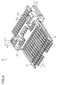
- Fig. 4 is a perspective view of the contact assembly 30 according to the present embodiment.
- the contact assembly 30 is an assembly which is formed by combining a plurality of contacts 33 forming a pair of upper and lower arrays, a pair of upper and lower bodies 31, and a pair of left and right spring pieces 32 with each other. Only the upper body 31 in a pair of upper and lower bodies 31 is focused and described below.
- the lower body 31 is obtained by merely disposing the upper body 31 in such a manner that front and back surfaces of the upper body 31 are reversed, and the lower body 31 has a shape identical to that of the upper body 31. On the upper surface of the body 31, the recess 311 is formed.
- first lateral walls 311a which are opposed to the connector pulling-out direction
- second lateral walls 311b which are opposed to the connector inserting direction
- third lateral walls 311c which are opposed to the extending direction of the arm portions 11 described above are formed.
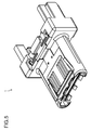
- Fig. 5 is a perspective view of the connector 1 according to the present embodiment. A relation among the arm portion 11, the hole 21d, and the recess 311 is described in detail below with reference to Figs. 6 to 10 .
- Fig. 6 is a front elevational view including indicating lines of sections of the connector 1 according to the present embodiment.
- Fig. 7 is a plan view of the connector 1 according to the present embodiment.
- Figs. 8 to 10 are sectional views which respectively correspond to section indicating lines which are respectively given reference numerals 8, 9, and 10 in Fig. 6 .
- the pressing portion 11b of the metal piece 10 is protruded from the hole 21d of the housing 20 toward the inner cavity of the housing 20 when the metal piece 10 is connected to the housing 20 and the body 31.
- a tip of the dowel 11b-1 of the pressing portion 11b is brought into contact only with the second lateral wall 311b of the recess 311 of the body 31.
- the dowel 11b-1 is a minute part, so that showing of the dowel 11b-1 is omitted in Figs. 7 to 10 .
- the third lateral wall 311 c is brought into contact with the convex portion 11c.
- the end surface, in the connector pulling-out direction, of the L-shaped portion 11 a (rear end surface) is not directly brought into contact with the first lateral wall 311 a but faces the first lateral wall 311a with a gap 52 interposed therebetween.
- the end surface (rear end surface), in the connector pulling-out direction, of the L-shaped portion 11a of the metal piece 10 is brought into contact only with the first lateral wall 21a of the concave portion 21 of the housing 20 when the metal piece 10 is connected with the housing 20.
- the pressing portion 11b of the arm portion 11 is not directly brought into contact with the end surface (rear end surface), in the connector pulling-out direction, of the hole 21d, but faces the end surface of the hole 21d with a gap 51 interposed therebetween.
- the rear end surface of the L-shaped portion 11 a has high rigidity with respect to a force of a direction in which this surface is pressed, and is hardly deformed. This is because the rear end surface of the L-shaped portion 11a corresponds to an edge portion (thickness) including a bending portion of a bent metal plate.
- the first lateral wall 21a of the housing 20 is brought into contact with the rear end surface of the L-shaped portion 11a having high rigidity, so that the metal piece 10 and the housing 20 are positioned properly.
- the rear end surface of the L-shaped portion 11a is not directly brought into contact with the first lateral wall 311a of the body 31, so that the rear end surface of the L-shaped portion 11a does not damage the body 31.
- the notch 11d described above is provided so that the arm portion 11 is easily inserted while avoiding contact between the rear end surface of the L-shaped portion 11 a and the first lateral wall 311a of the body 31.
- the pressing portion 11b of the metal piece 10 can elastically deform to a small extent in the connector inserting/pulling-out direction. Therefore, when the metal piece 10 is fitted in the housing 20 and the body 31, the pressing portion 11b presses the body 31 slightly forward (connector inserting direction) by an elastic force thereof.
- the pressing portion 11b of the metal piece 10 is formed to have some flexibility, so that the contact assembly 30 can be positioned in such a manner that the whole of the contact assembly 30 is gently pressed forward without damaging the body 31. Even though the lateral wall and the like of the recess 311 described above have the thin configurations, these portions can be prevented from being damaged. Therefore, the body 31 can be reduced in size and weight. Accordingly, the whole of the connector 1 can be reduced in size and weight.
- the dowel 11b-1 is formed near the center of the pressing portion 11b, so that the contact assembly 30 is properly positioned with reference to the tip (pointed end) of the dowel 11b-1. Accordingly, even if the contact assembly 30 is accommodated in a manner to be slightly shifted in the connector pulling-out direction, the insertion of the lower end of the pressing portion 11b is not prevented.
- the dowel 11b-1 is formed to have a hemisphere shape or a gentle convex surface, the dowel 11b-1 gently presses the second lateral wall 311b along with the insertion of the arm portion 11. Thus, a load on the second lateral wall 311b which is a thin portion of the body 31 can be reduced.
- the metal piece 10 can be said to be an essential constituent part.
- the part positioning function is imparted to the metal piece 10 which is an essential part, being able to reduce the number of parts of a connector and contributing to reduce the size of the connector and man-hours in connector manufacturing.
Landscapes
- Details Of Connecting Devices For Male And Female Coupling (AREA)
- Coupling Device And Connection With Printed Circuit (AREA)
- Connector Housings Or Holding Contact Members (AREA)
Abstract
Description
- The present invention relates to a connector.
- As the configuration of a connector of prior art and the configuration around a contact of the connector, those in Japanese Patent Application Laid Open No.
2010-073549 - In a case of a small connector, positioning of parts which constitute a connector is sometimes difficult. For example, in a case where the spring structure is used for fixing of resin-molded parts, small parts or thin portions of a part are sometimes damaged due to stress of the spring.
- On the other hand, when parts which are stressed are formed large to some extent so as to avoid damage or breaking, reduction of a size of a connector is sometimes prevented.
- Therefore, an object of the present invention is to provide a connector which enables positioning of parts constituting the connector while preventing damage of the parts even though the parts are small and thin.
- A connector according to the present invention includes a metal piece, a contact assembly including a body which fixes a plurality of contacts, and a housing in which the contact assembly is inserted in a connector inserting direction to be accommodated.
- The housing includes a concave portion which has a lateral wall which is opposed to a connector pulling-out direction, and a hole which is formed on a bottom surface of the concave portion.
- The body includes a recess which has a lateral wall which is opposed to the connector inserting direction.
- The metal piece includes an arm portion which is extended in an arrangement direction of the contacts, an L-shaped portion which is formed in a manner to be bent in a direction orthogonal to both of an extending direction of the arm portion and the connector inserting direction, and of which an end surface, in the connector pulling-out direction, is brought into contact only with the lateral wall of the concave portion of the housing in a case of connection with the housing, and a pressing portion which is formed by extending an end surface, in the connector inserting direction, of the L-shaped portion in a forward direction or an inverse direction of the extending direction of the arm portion, and which protrudes from the hole to be brought into contact only with the lateral wall of the recess of the body in a case of connection with the housing and the body.
- According to the connector of the present invention, positioning of parts constituting the connector can be performed while preventing damage of the parts even though the parts are small and thin.
-
-
Fig. 1 is an exploded perspective view of a connector according to a first embodiment. -
Fig. 2 is a perspective view of a pair of upper and lower metal pieces according to the first embodiment. -
Fig. 3 is a perspective view of a housing according to the first embodiment. -
Fig. 4 is a perspective view of a contact assembly according to the first embodiment. -
Fig. 5 is a perspective view of the connector according to the first embodiment. -
Fig. 6 is a front elevational view including indicating lines of sections of the connector according to the first embodiment. -
Fig. 7 is a plan view of the connector according to the first embodiment. -
Fig. 8 is a sectional view of the connector according to the first embodiment. -
Fig. 9 is a sectional view of the connector according to the first embodiment. -
Fig. 10 is a sectional view of the connector according to the first embodiment. - An embodiment of the present invention is described in detail below. Here, constituent parts having identical functions to each other are given identical reference characters and duplicate description of the parts is omitted.
- Each constituent part of a connector according to the first embodiment is described below with reference to
Fig. 1. Fig. 1 is an exploded perspective view of aconnector 1 according to the present embodiment. As illustrated inFig. 1 , theconnector 1 of the present embodiment is composed of a pair of upper andlower metal pieces 10, ahousing 20, and acontact assembly 30. Thecontact assembly 30 is an assembly which is formed by combining a plurality ofcontacts 33 forming a pair of upper and lower arrays, a pair of upper andlower bodies 31 which respectively fix the pair of upper and lower contact arrays, and a pair of left andright spring pieces 32 which are fixed in a manner to be sandwiched by the pair of upper andlower bodies 31 with each other. The upper andlower bodies 31 which make a pair are connected with each other in such a manner that bottom surfaces thereof face each other. The pair of left andright spring pieces 32 is fixed in a manner to be sandwiched by the bottom surfaces of the upper andlower bodies 31. Thespring pieces 32 functions to hold a connector which is a fitting counterpart. On upper surfaces (another surfaces of the bottom surfaces which face each other) of thebodies 31, arecess 311 is formed. Thehousing 20 is a casing which has an opening in a connector pulling-out direction. From the opening of thehousing 20, thecontact assembly 30 can be inserted in a connector inserting direction. A pair of left andright holes 21d is formed on each of the upper surface and the lower surface of thehousing 20. Therecess 311 and thehole 21d are formed to have such shapes that a part of therecess 311 and thehole 21d are fitted to each other when thecontact assembly 30 is accommodated in thehousing 20. Themetal piece 10 hasarm portions 11 which are extended in an arrangement direction of thecontacts 33. Thearm portions 11 are formed such that thearm portions 11 are inserted from the upper surface side (and the lower surface side) of thehousing 20 into theholes 21d to be fitted in theholes 21d. In this case, thearm portions 11 protrude toward an inner cavity of thehousing 20 from theholes 21d to be fitted in a part of a shape of therecess 311. Thearm portions 11 are thus fitted in both of theholes 21d and a part of the shape of therecess 311. Therefore, a pair ofmetal pieces 10, thehousing 20, and thecontact assembly 30 can be positioned on each other, and these parts can be connected and fixed to each other. Here, themetal pieces 10 are brought into contact with a shield cover which is not illustrated in the drawing. - The configuration of the
metal piece 10 is described in detail below with reference toFig. 2. Fig. 2 is a perspective view of a pair of upper andlower metal pieces 10 according to the present embodiment. In the following description, only theupper metal piece 10 in a pair of upper andlower metal pieces 10 is focused and described. Thelower metal piece 10 is obtained by merely disposing theupper metal piece 10 in such a manner that front and back surfaces of theupper metal piece 10 are reversed, and thelower metal piece 10 has a shape identical to that of theupper metal piece 10. As illustrated inFig. 2 , themetal piece 10 is provided with acontact portion 14 which is brought into contact with a metal piece of a counterpart connector in coupling with the counterpart connector. Thecontact portion 14 has an approximate frame shape and on an end of thecontact portion 14 in a connector inserting direction, three pieces ofcontact pieces 14a are arranged. Here, theconnector 1 of the present embodiment is designed in accordance with a standard of USB-Type C, and shapes of six pieces, in total, ofcontact pieces 14a of the upper andlower metal pieces 10 are an essential shape for USB-Type C. An end portion, in the connector pulling-out direction, of thecontact portion 14 is extended in the connector pulling-out direction so as to form acoupling portion 13. To the connector pulling-out direction of thecoupling portion 13, asupport portion 12 which has a substantially L-shaped section is connected. Thesupport portion 12 is composed of a lateral surface which vertically erects in an upward direction from thecoupling portion 13 and an upper surface which is formed by bending the lateral surface in a horizontal direction. The upper surface of thesupport portion 12 is connected with thearm portions 11. Thearm portion 11 represents a portion including an L-shaped portion 11a, apressing portion 11b, adowel 11b-1, aconvex portion 11c, anotch 11d, and a protrudingportion 11e. The upper surface of thesupport portion 12 is extended in a left and right direction (an arrangement direction of the contacts 33) of themetal piece 10 so as to form theprotruding portion 11e. An end of theprotruding portion 11e is bent to a downward direction so as to form the L-shaped portion 11a. Not limited to this, the L-shaped portion 11a may be formed by bending the end of the protrudingportion 11e to an upward direction. Thus, the L-shaped portion 11a is formed by bending the end of the protrudingportion 11e to either the downward direction or the upward direction (either one of two directions which are orthogonal to both of the extending direction of theprotruding portion 11e and the connector inserting direction). On an upper surface and a lateral surface of the L-shaped portion 11a, a line ofconvex portion 11c which has a substantially semicircular section is formed. Thenotch 11d is formed on a part on the lower side of an end surface, in the connector pulling-out direction, of the L-shaped portion 11a. An end surface, in the connector inserting direction, of the L-shaped portion 11a is bent and extended in an opposite direction of the extending direction of theprotruding portion 11e so as to form thepressing portion 11b. Not limited to this, thepressing portion 11b may be formed by bending and extending the end surface of the L-shapedportion 11 a in the forward direction of the extending direction of the protrudingportion 11e. Thepressing portion 11b is coupled with the L-shapedportion 11a only on a bending part, so that some deflection is permitted in the connector inserting/pulling-out direction. That is, thepressing portion 11b serves as a spring piece which elastically deforms to a small extent in the connector inserting/pulling-out direction. Near the center of a surface, which is opposed to the connector pulling-out direction, of thepressing portion 11b, thedowel 11b-1 is formed. - Subsequently, the configuration of the
housing 20 is described in detail with reference toFig. 3. Fig. 3 is a perspective view of thehousing 20 according to the present embodiment. As illustrated inFig. 3 , thehousing 20 is composed of a protrudingportion 22 which accommodates end portions of thecontacts 33 and abase portion 23 which accommodates thebodies 31. Each of the protrudingportion 22 and thebase portion 23 of thehousing 20 has the same configurations on an upper surface and a lower surface. On the upper surface and the lower surface of thebase portion 23,concave portions 21 are respectively formed. On both left and right ends of a pair of upper and lowerconcave portions 21, firstlateral walls 21a which are opposed to the connector pulling-out direction and thirdlateral walls 21c which are opposed to the extending direction of thearm portions 11 which are described above are formed. A pair of left andright holes 21d is formed on bottom surfaces of the pair of upper and lowerconcave portions 21. Thehole 21d is formed in a region sandwiched (surrounded) by the firstlateral wall 21a and the thirdlateral wall 21c. Thehole 21d is formed in a shape and a dimension which permit insertion of the lower end portion of the L-shapedportion 11a described above and thepressing portion 11b described above. - Next, the configuration of the
body 31 is described in detail with reference toFig. 4. Fig. 4 is a perspective view of thecontact assembly 30 according to the present embodiment. As mentioned above, thecontact assembly 30 is an assembly which is formed by combining a plurality ofcontacts 33 forming a pair of upper and lower arrays, a pair of upper andlower bodies 31, and a pair of left andright spring pieces 32 with each other. Only theupper body 31 in a pair of upper andlower bodies 31 is focused and described below. Thelower body 31 is obtained by merely disposing theupper body 31 in such a manner that front and back surfaces of theupper body 31 are reversed, and thelower body 31 has a shape identical to that of theupper body 31. On the upper surface of thebody 31, therecess 311 is formed. On both of left and right ends of therecess 311, firstlateral walls 311a which are opposed to the connector pulling-out direction, secondlateral walls 311b which are opposed to the connector inserting direction, and thirdlateral walls 311c which are opposed to the extending direction of thearm portions 11 described above are formed. - As described above, the
contact assembly 30 is accommodated in thehousing 20 and the upper andlower metal pieces 10, which make a pair, are coupled from the upper direction and the lower direction of thehousing 20 respectively so as to form theconnector 1 illustrated inFig. 5. Fig. 5 is a perspective view of theconnector 1 according to the present embodiment. A relation among thearm portion 11, thehole 21d, and therecess 311 is described in detail below with reference toFigs. 6 to 10 .Fig. 6 is a front elevational view including indicating lines of sections of theconnector 1 according to the present embodiment.Fig. 7 is a plan view of theconnector 1 according to the present embodiment.Figs. 8 to 10 are sectional views which respectively correspond to section indicating lines which are respectively givenreference numerals Fig. 6 . - As illustrated in
Fig. 7 andFig. 8 , thepressing portion 11b of themetal piece 10 is protruded from thehole 21d of thehousing 20 toward the inner cavity of thehousing 20 when themetal piece 10 is connected to thehousing 20 and thebody 31. At this time, a tip of thedowel 11b-1 of thepressing portion 11b is brought into contact only with the secondlateral wall 311b of therecess 311 of thebody 31. Here, thedowel 11b-1 is a minute part, so that showing of thedowel 11b-1 is omitted inFigs. 7 to 10 . Further, as illustrated inFig. 8 , the thirdlateral wall 311 c is brought into contact with theconvex portion 11c. Further, the end surface, in the connector pulling-out direction, of the L-shapedportion 11 a (rear end surface) is not directly brought into contact with the firstlateral wall 311 a but faces the firstlateral wall 311a with agap 52 interposed therebetween. - As illustrated in
Fig. 9 andFig. 10 , the end surface (rear end surface), in the connector pulling-out direction, of the L-shapedportion 11a of themetal piece 10 is brought into contact only with the firstlateral wall 21a of theconcave portion 21 of thehousing 20 when themetal piece 10 is connected with thehousing 20. As illustrated inFig. 10 , thepressing portion 11b of thearm portion 11 is not directly brought into contact with the end surface (rear end surface), in the connector pulling-out direction, of thehole 21d, but faces the end surface of thehole 21d with agap 51 interposed therebetween. - The rear end surface of the L-shaped
portion 11 a has high rigidity with respect to a force of a direction in which this surface is pressed, and is hardly deformed. This is because the rear end surface of the L-shapedportion 11a corresponds to an edge portion (thickness) including a bending portion of a bent metal plate. As mentioned above, the firstlateral wall 21a of thehousing 20 is brought into contact with the rear end surface of the L-shapedportion 11a having high rigidity, so that themetal piece 10 and thehousing 20 are positioned properly. On the other hand, the rear end surface of the L-shapedportion 11a is not directly brought into contact with the firstlateral wall 311a of thebody 31, so that the rear end surface of the L-shapedportion 11a does not damage thebody 31. Thenotch 11d described above is provided so that thearm portion 11 is easily inserted while avoiding contact between the rear end surface of the L-shapedportion 11 a and the firstlateral wall 311a of thebody 31. - On the other hand, the
pressing portion 11b of themetal piece 10 can elastically deform to a small extent in the connector inserting/pulling-out direction. Therefore, when themetal piece 10 is fitted in thehousing 20 and thebody 31, thepressing portion 11b presses thebody 31 slightly forward (connector inserting direction) by an elastic force thereof. Thepressing portion 11b of themetal piece 10 is formed to have some flexibility, so that thecontact assembly 30 can be positioned in such a manner that the whole of thecontact assembly 30 is gently pressed forward without damaging thebody 31. Even though the lateral wall and the like of therecess 311 described above have the thin configurations, these portions can be prevented from being damaged. Therefore, thebody 31 can be reduced in size and weight. Accordingly, the whole of theconnector 1 can be reduced in size and weight. - Further, the
dowel 11b-1 is formed near the center of thepressing portion 11b, so that thecontact assembly 30 is properly positioned with reference to the tip (pointed end) of thedowel 11b-1. Accordingly, even if thecontact assembly 30 is accommodated in a manner to be slightly shifted in the connector pulling-out direction, the insertion of the lower end of thepressing portion 11b is not prevented. When thedowel 11b-1 is formed to have a hemisphere shape or a gentle convex surface, thedowel 11b-1 gently presses the secondlateral wall 311b along with the insertion of thearm portion 11. Thus, a load on the secondlateral wall 311b which is a thin portion of thebody 31 can be reduced. - Further, six pieces, in total, of
contact pieces 14a of thecontact portion 14 of the upper andlower metal pieces 10 have shapes necessary for contact with a metal plate of a counterpart connector in USB-Type C standard. Therefore, themetal piece 10 can be said to be an essential constituent part. Thus, the part positioning function is imparted to themetal piece 10 which is an essential part, being able to reduce the number of parts of a connector and contributing to reduce the size of the connector and man-hours in connector manufacturing. - The foregoing description of the embodiments of the invention has been presented for the purpose of illustration and description. It is not intended to be exhaustive and to limit the invention to the precise form disclosed. Modifications or variations are possible in light of the above teaching. The embodiment was chosen and described to provide the best illustration of the principles of the invention and its practical application, and to enable one of ordinary skill in the art to utilize the invention in various embodiments and with various modifications as are suited to the particular use contemplated. All such modifications and variations are within the scope of the invention as determined by the appended claims when interpreted in accordance with the breadth to which they are fairly, legally, and equitably entitled.
Claims (4)
- A connector (1) comprising:a metal piece (10);a contact assembly (30) including a body (31) which fixes a plurality of contacts (33); anda housing (20) in which the contact assembly (30) is inserted in a connector (1) inserting direction to be accommodated; whereinthe housing (20) includes
a concave portion (21) which has a lateral wall (21a) which is opposed to a connector (1) pulling-out direction, and
a hole (21d) which is formed on a bottom surface of the concave portion (21),the body (31) includes
a recess (311) which has a lateral wall (311b) which is opposed to the connector (1) inserting direction, andthe metal piece (10) includes
an arm portion (11) which is extended in an arrangement direction of the contacts (33),
an L-shaped portion (11a) which is formed in a manner to be bent in a direction orthogonal to both of an extending direction of the arm portion (11) and the connector (1) inserting direction, and of which an end surface, in the connector (1) pulling-out direction, is brought into contact only with the lateral wall (21a) of the concave portion (21) of the housing (20) in a case of connection with the housing (20), and
a pressing portion (11b) which is formed by extending an end surface, in the connector (1) inserting direction, of the L-shaped portion (11a) in a forward direction or an inverse direction of the extending direction of the arm portion (11), and which protrudes from the hole (21d) to be brought into contact only with the lateral wall (311b) of the recess (311) of the body (31) in a case of connection with the housing (20) and the body (31). - The connector (1) according to claim 1, wherein
a dowel (11b-1) which is brought into contact only with the lateral wall (311b) of the recess (311) of the body (31) is provided on a surface, the surface being opposed to the connector (1) pulling-out direction, of the pressing portion (11b). - The connector (1) according to claim 1 or 2, wherein
a notch (11d) is provided on a lower portion of the end surface, in the connector (1) pulling-out direction, of the L-shaped portion (11a). - The connector (1) according to one of claims 1 to 3, wherein
the metal piece (10) includes a contact portion (14) which is brought into contact with a metal plate of a counterpart connector in coupling with the counterpart connector.
Applications Claiming Priority (1)
| Application Number | Priority Date | Filing Date | Title |
|---|---|---|---|
| JP2014174304A JP6259735B2 (en) | 2014-08-28 | 2014-08-28 | connector |
Publications (2)
| Publication Number | Publication Date |
|---|---|
| EP2991174A1 true EP2991174A1 (en) | 2016-03-02 |
| EP2991174B1 EP2991174B1 (en) | 2017-05-17 |
Family
ID=53871984
Family Applications (1)
| Application Number | Title | Priority Date | Filing Date |
|---|---|---|---|
| EP15181372.2A Not-in-force EP2991174B1 (en) | 2014-08-28 | 2015-08-18 | Usb type c connector |
Country Status (6)
| Country | Link |
|---|---|
| US (1) | US9461425B2 (en) |
| EP (1) | EP2991174B1 (en) |
| JP (1) | JP6259735B2 (en) |
| KR (1) | KR102285273B1 (en) |
| CN (1) | CN105390847B (en) |
| TW (1) | TWI641188B (en) |
Cited By (4)
| Publication number | Priority date | Publication date | Assignee | Title |
|---|---|---|---|---|
| WO2017206404A1 (en) * | 2016-06-02 | 2017-12-07 | 乐视控股(北京)有限公司 | Usb type-c interface |
| TWI651904B (en) * | 2017-08-17 | 2019-02-21 | 禾昌興業股份有限公司 | Electrical connector |
| WO2020077012A1 (en) * | 2018-10-11 | 2020-04-16 | Masimo Corporation | Patient connector assembly with vertical detents |
| USD1049116S1 (en) | 2015-03-06 | 2024-10-29 | Apple Inc. | Electronic device with connector |
Families Citing this family (15)
| Publication number | Priority date | Publication date | Assignee | Title |
|---|---|---|---|---|
| WO2015016778A1 (en) * | 2013-07-29 | 2015-02-05 | Fci Connectors Singapore Pte Ltd | Modular jack connector and terminal module |
| USD786798S1 (en) * | 2014-05-26 | 2017-05-16 | Japan Aviation Electronics Industry, Limited | Electrical connector |
| JP6293580B2 (en) * | 2014-06-03 | 2018-03-14 | 日本航空電子工業株式会社 | connector |
| CN204538364U (en) * | 2014-06-13 | 2015-08-05 | 番禺得意精密电子工业有限公司 | Electric connector |
| CN105703137B (en) * | 2014-11-25 | 2018-10-02 | 富士康(昆山)电脑接插件有限公司 | Micro coaxial cable connector assembly and its manufacturing method |
| JP6292201B2 (en) * | 2015-09-18 | 2018-03-14 | Smk株式会社 | Electrical connector |
| JP6513542B2 (en) * | 2015-09-29 | 2019-05-15 | 日本航空電子工業株式会社 | Connector and connector assembly |
| JP6058771B1 (en) * | 2015-10-13 | 2017-01-11 | 日本航空電子工業株式会社 | Receptacle connector |
| US9425560B1 (en) * | 2015-10-15 | 2016-08-23 | Cheng Uei Precision Industry Co., Ltd. | Electrical connector |
| WO2017078763A1 (en) | 2015-11-06 | 2017-05-11 | Molex, Llc | Compact high speed connector |
| JP1577462S (en) * | 2016-11-14 | 2017-05-29 | ||
| CN108092031B (en) * | 2016-11-23 | 2020-06-02 | 富士康(昆山)电脑接插件有限公司 | Plug connector assembly |
| US10637181B2 (en) * | 2017-08-15 | 2020-04-28 | Masimo Corporation | Water resistant connector for noninvasive patient monitor |
| US11990710B2 (en) * | 2018-11-28 | 2024-05-21 | Microsoft Technology Licensing Llc | Shell-less electrical connector and method of making same |
| JP7476705B2 (en) * | 2020-07-27 | 2024-05-01 | I-Pex株式会社 | Housings and Connectors |
Citations (6)
| Publication number | Priority date | Publication date | Assignee | Title |
|---|---|---|---|---|
| JP2010073549A (en) | 2008-09-19 | 2010-04-02 | Panasonic Electric Works Co Ltd | Connector, and method of manufacturing the same |
| US20100232118A1 (en) * | 2009-03-10 | 2010-09-16 | J.S.T. Mfg. Co., Ltd. | Component joining structure, IC card, and connector |
| CN201797116U (en) * | 2010-07-02 | 2011-04-13 | 诠欣股份有限公司 | electrical connector |
| US20140073190A1 (en) * | 2012-09-11 | 2014-03-13 | Hon Hai Precision Industry Co., Ltd. | Socket connector with a sub-shell flexibly connect with a printed circuit board |
| TWM480792U (en) * | 2014-01-23 | 2014-06-21 | Advanced Connectek Inc | Reinforcing structure of socket connector |
| TWM484832U (en) * | 2014-04-28 | 2014-08-21 | Speedtech Corp | Universal serial bus connector |
Family Cites Families (23)
| Publication number | Priority date | Publication date | Assignee | Title |
|---|---|---|---|---|
| JPH0756821B2 (en) * | 1988-05-20 | 1995-06-14 | 菱星電装株式会社 | Connector housing |
| JP3097825B2 (en) * | 1995-10-20 | 2000-10-10 | 矢崎総業株式会社 | Connector device |
| JP2000138079A (en) * | 1998-10-30 | 2000-05-16 | Molex Inc | Connector for connecting substrate |
| JP2000223218A (en) * | 1999-01-27 | 2000-08-11 | Mitsumi Electric Co Ltd | Small connector |
| US6231355B1 (en) * | 1999-12-17 | 2001-05-15 | Hon Hai Precision Ind. Co., Ltd. | Matched impedance connector having retention device on a grounding plane |
| US6402554B1 (en) * | 2001-02-16 | 2002-06-11 | Hon Hai Precision Ind. Co., Ltd. | Vertical SMT-type electrical connector |
| CN2850025Y (en) * | 2005-11-14 | 2006-12-20 | 富士康(昆山)电脑接插件有限公司 | Speech socket connector |
| CN201029145Y (en) * | 2007-03-02 | 2008-02-27 | 富士康(昆山)电脑接插件有限公司 | electrical connector |
| CN201230066Y (en) * | 2008-07-02 | 2009-04-29 | 富士康(昆山)电脑接插件有限公司 | Electric connector |
| TWM350153U (en) * | 2008-08-22 | 2009-02-01 | Taiwin Electronics Co Ltd | |
| CN201374433Y (en) * | 2009-01-22 | 2009-12-30 | 上海莫仕连接器有限公司 | Electric connector |
| CN201440537U (en) * | 2009-06-30 | 2010-04-21 | 富士康(昆山)电脑接插件有限公司 | Electric connector |
| CN201584612U (en) * | 2009-12-18 | 2010-09-15 | 莫列斯公司 | Electric connector of socket and electric connector combination |
| JP5822328B2 (en) * | 2010-08-31 | 2015-11-24 | 矢崎総業株式会社 | Board mounted connector |
| JP2012146401A (en) * | 2011-01-07 | 2012-08-02 | Alps Electric Co Ltd | Connector device |
| CN102916286B (en) * | 2011-08-02 | 2015-05-27 | 富士康(昆山)电脑接插件有限公司 | Electrical connector |
| TW201318280A (en) * | 2011-10-27 | 2013-05-01 | Santa Electronics Inc | Electrical connector |
| US8684769B2 (en) * | 2012-05-24 | 2014-04-01 | Hon Hai Precision Industry Co., Ltd. | Electrical connector having terminal portions in specific arrangement and a grounding plate for excellent high-frequency characteristics |
| US8961235B2 (en) * | 2012-10-19 | 2015-02-24 | Hon Hai Precision Industry Co., Ltd. | Electrical connector with improved mating member having anti-mismating portion for preventing incorrect insertion |
| US8851927B2 (en) * | 2013-02-02 | 2014-10-07 | Hon Hai Precision Industry Co., Ltd. | Electrical connector with shielding and grounding features thereof |
| US9022800B2 (en) * | 2013-05-23 | 2015-05-05 | Hon Hai Precision Industry Co., Ltd. | Electrical connector with heat-dissipation feauter thereof |
| CN203800267U (en) * | 2014-02-11 | 2014-08-27 | 深圳市万顺通科技有限公司 | USB interface and mobile power supply comprising same |
| CN105470690A (en) * | 2014-09-05 | 2016-04-06 | 凡甲电子(苏州)有限公司 | Electric connector and manufacturing method thereof |
-
2014
- 2014-08-28 JP JP2014174304A patent/JP6259735B2/en active Active
-
2015
- 2015-06-26 KR KR1020150091090A patent/KR102285273B1/en not_active Expired - Fee Related
- 2015-07-17 US US14/802,245 patent/US9461425B2/en not_active Expired - Fee Related
- 2015-07-20 TW TW104123402A patent/TWI641188B/en not_active IP Right Cessation
- 2015-08-17 CN CN201510503879.6A patent/CN105390847B/en not_active Expired - Fee Related
- 2015-08-18 EP EP15181372.2A patent/EP2991174B1/en not_active Not-in-force
Patent Citations (8)
| Publication number | Priority date | Publication date | Assignee | Title |
|---|---|---|---|---|
| JP2010073549A (en) | 2008-09-19 | 2010-04-02 | Panasonic Electric Works Co Ltd | Connector, and method of manufacturing the same |
| US20100232118A1 (en) * | 2009-03-10 | 2010-09-16 | J.S.T. Mfg. Co., Ltd. | Component joining structure, IC card, and connector |
| CN201797116U (en) * | 2010-07-02 | 2011-04-13 | 诠欣股份有限公司 | electrical connector |
| US20140073190A1 (en) * | 2012-09-11 | 2014-03-13 | Hon Hai Precision Industry Co., Ltd. | Socket connector with a sub-shell flexibly connect with a printed circuit board |
| TWM480792U (en) * | 2014-01-23 | 2014-06-21 | Advanced Connectek Inc | Reinforcing structure of socket connector |
| US20150207281A1 (en) * | 2014-01-23 | 2015-07-23 | Advanced-Connectek Inc. | Reinforcing structure of electrical receptacle connector |
| TWM484832U (en) * | 2014-04-28 | 2014-08-21 | Speedtech Corp | Universal serial bus connector |
| US20150311645A1 (en) * | 2014-04-28 | 2015-10-29 | Speed Tech Corp. | Universal serial bus connector |
Cited By (8)
| Publication number | Priority date | Publication date | Assignee | Title |
|---|---|---|---|---|
| USD1049116S1 (en) | 2015-03-06 | 2024-10-29 | Apple Inc. | Electronic device with connector |
| WO2017206404A1 (en) * | 2016-06-02 | 2017-12-07 | 乐视控股(北京)有限公司 | Usb type-c interface |
| TWI651904B (en) * | 2017-08-17 | 2019-02-21 | 禾昌興業股份有限公司 | Electrical connector |
| WO2020077012A1 (en) * | 2018-10-11 | 2020-04-16 | Masimo Corporation | Patient connector assembly with vertical detents |
| KR20210084491A (en) * | 2018-10-11 | 2021-07-07 | 마시모 코오퍼레이션 | Patient connector assembly with vertical detents |
| US11445948B2 (en) | 2018-10-11 | 2022-09-20 | Masimo Corporation | Patient connector assembly with vertical detents |
| EP4258492A2 (en) | 2018-10-11 | 2023-10-11 | Masimo Corporation | Patient connector assembly with vertical detents |
| US12156732B2 (en) | 2018-10-11 | 2024-12-03 | Masimo Corporation | Patient connector assembly with vertical detents |
Also Published As
| Publication number | Publication date |
|---|---|
| US9461425B2 (en) | 2016-10-04 |
| US20160064877A1 (en) | 2016-03-03 |
| EP2991174B1 (en) | 2017-05-17 |
| KR102285273B1 (en) | 2021-08-02 |
| CN105390847B (en) | 2018-12-07 |
| JP6259735B2 (en) | 2018-01-10 |
| TWI641188B (en) | 2018-11-11 |
| KR20160026662A (en) | 2016-03-09 |
| JP2016051514A (en) | 2016-04-11 |
| TW201626651A (en) | 2016-07-16 |
| CN105390847A (en) | 2016-03-09 |
Similar Documents
| Publication | Publication Date | Title |
|---|---|---|
| EP2991174B1 (en) | Usb type c connector | |
| JP6325505B2 (en) | connector | |
| JP6084133B2 (en) | connector | |
| US9774124B2 (en) | Connector | |
| JP5835491B2 (en) | Coaxial connector | |
| CN103001034A (en) | Electric connector | |
| CN102904086A (en) | Connector, and performance plate, mother plate and a semiconductor testing device containing same | |
| JP2022186850A (en) | movable connector | |
| KR20110044813A (en) | Micro USB Socket | |
| JP6727035B2 (en) | Blade body | |
| TWM553061U (en) | Electrical receptacle connector | |
| JP6095182B2 (en) | Contacts and connectors | |
| JP6886910B2 (en) | Connector assembly | |
| JP6114672B2 (en) | connector | |
| TWI697158B (en) | Tray | |
| JP6858949B2 (en) | Contacts, connector members and connectors | |
| JP5626106B2 (en) | Electronic device housing structure | |
| JP2017162648A (en) | connector | |
| JP5872970B2 (en) | Connector terminal and connection structure between this connector terminal and mating terminal | |
| CN202205914U (en) | electrical connector | |
| KR101346093B1 (en) | Receptacle Terminal | |
| JP5841425B2 (en) | Contact unit for sockets for electrical parts | |
| KR100827961B1 (en) | Connector | |
| JP6784393B2 (en) | connector |
Legal Events
| Date | Code | Title | Description |
|---|---|---|---|
| PUAI | Public reference made under article 153(3) epc to a published international application that has entered the european phase |
Free format text: ORIGINAL CODE: 0009012 |
|
| AK | Designated contracting states |
Kind code of ref document: A1 Designated state(s): AL AT BE BG CH CY CZ DE DK EE ES FI FR GB GR HR HU IE IS IT LI LT LU LV MC MK MT NL NO PL PT RO RS SE SI SK SM TR |
|
| AX | Request for extension of the european patent |
Extension state: BA ME |
|
| 17P | Request for examination filed |
Effective date: 20160412 |
|
| RBV | Designated contracting states (corrected) |
Designated state(s): AL AT BE BG CH CY CZ DE DK EE ES FI FR GB GR HR HU IE IS IT LI LT LU LV MC MK MT NL NO PL PT RO RS SE SI SK SM TR |
|
| 17Q | First examination report despatched |
Effective date: 20161011 |
|
| STAA | Information on the status of an ep patent application or granted ep patent |
Free format text: STATUS: EXAMINATION IS IN PROGRESS |
|
| GRAP | Despatch of communication of intention to grant a patent |
Free format text: ORIGINAL CODE: EPIDOSNIGR1 |
|
| RIC1 | Information provided on ipc code assigned before grant |
Ipc: H01R 13/6593 20110101ALI20161215BHEP Ipc: H01R 13/508 20060101ALI20161215BHEP Ipc: H01R 24/60 20110101AFI20161215BHEP Ipc: H01R 107/00 20060101ALN20161215BHEP |
|
| STAA | Information on the status of an ep patent application or granted ep patent |
Free format text: STATUS: GRANT OF PATENT IS INTENDED |
|
| INTG | Intention to grant announced |
Effective date: 20170119 |
|
| GRAS | Grant fee paid |
Free format text: ORIGINAL CODE: EPIDOSNIGR3 |
|
| GRAA | (expected) grant |
Free format text: ORIGINAL CODE: 0009210 |
|
| STAA | Information on the status of an ep patent application or granted ep patent |
Free format text: STATUS: THE PATENT HAS BEEN GRANTED |
|
| AK | Designated contracting states |
Kind code of ref document: B1 Designated state(s): AL AT BE BG CH CY CZ DE DK EE ES FI FR GB GR HR HU IE IS IT LI LT LU LV MC MK MT NL NO PL PT RO RS SE SI SK SM TR |
|
| REG | Reference to a national code |
Ref country code: GB Ref legal event code: FG4D |
|
| REG | Reference to a national code |
Ref country code: CH Ref legal event code: EP |
|
| REG | Reference to a national code |
Ref country code: IE Ref legal event code: FG4D |
|
| REG | Reference to a national code |
Ref country code: AT Ref legal event code: REF Ref document number: 895239 Country of ref document: AT Kind code of ref document: T Effective date: 20170615 |
|
| REG | Reference to a national code |
Ref country code: DE Ref legal event code: R096 Ref document number: 602015002741 Country of ref document: DE |
|
| REG | Reference to a national code |
Ref country code: FR Ref legal event code: PLFP Year of fee payment: 3 |
|
| REG | Reference to a national code |
Ref country code: NL Ref legal event code: MP Effective date: 20170517 |
|
| REG | Reference to a national code |
Ref country code: LT Ref legal event code: MG4D |
|
| REG | Reference to a national code |
Ref country code: AT Ref legal event code: MK05 Ref document number: 895239 Country of ref document: AT Kind code of ref document: T Effective date: 20170517 |
|
| PG25 | Lapsed in a contracting state [announced via postgrant information from national office to epo] |
Ref country code: HR Free format text: LAPSE BECAUSE OF FAILURE TO SUBMIT A TRANSLATION OF THE DESCRIPTION OR TO PAY THE FEE WITHIN THE PRESCRIBED TIME-LIMIT Effective date: 20170517 Ref country code: ES Free format text: LAPSE BECAUSE OF FAILURE TO SUBMIT A TRANSLATION OF THE DESCRIPTION OR TO PAY THE FEE WITHIN THE PRESCRIBED TIME-LIMIT Effective date: 20170517 Ref country code: AT Free format text: LAPSE BECAUSE OF FAILURE TO SUBMIT A TRANSLATION OF THE DESCRIPTION OR TO PAY THE FEE WITHIN THE PRESCRIBED TIME-LIMIT Effective date: 20170517 Ref country code: LT Free format text: LAPSE BECAUSE OF FAILURE TO SUBMIT A TRANSLATION OF THE DESCRIPTION OR TO PAY THE FEE WITHIN THE PRESCRIBED TIME-LIMIT Effective date: 20170517 Ref country code: NO Free format text: LAPSE BECAUSE OF FAILURE TO SUBMIT A TRANSLATION OF THE DESCRIPTION OR TO PAY THE FEE WITHIN THE PRESCRIBED TIME-LIMIT Effective date: 20170817 Ref country code: GR Free format text: LAPSE BECAUSE OF FAILURE TO SUBMIT A TRANSLATION OF THE DESCRIPTION OR TO PAY THE FEE WITHIN THE PRESCRIBED TIME-LIMIT Effective date: 20170818 Ref country code: FI Free format text: LAPSE BECAUSE OF FAILURE TO SUBMIT A TRANSLATION OF THE DESCRIPTION OR TO PAY THE FEE WITHIN THE PRESCRIBED TIME-LIMIT Effective date: 20170517 |
|
| PG25 | Lapsed in a contracting state [announced via postgrant information from national office to epo] |
Ref country code: RS Free format text: LAPSE BECAUSE OF FAILURE TO SUBMIT A TRANSLATION OF THE DESCRIPTION OR TO PAY THE FEE WITHIN THE PRESCRIBED TIME-LIMIT Effective date: 20170517 Ref country code: NL Free format text: LAPSE BECAUSE OF FAILURE TO SUBMIT A TRANSLATION OF THE DESCRIPTION OR TO PAY THE FEE WITHIN THE PRESCRIBED TIME-LIMIT Effective date: 20170517 Ref country code: SE Free format text: LAPSE BECAUSE OF FAILURE TO SUBMIT A TRANSLATION OF THE DESCRIPTION OR TO PAY THE FEE WITHIN THE PRESCRIBED TIME-LIMIT Effective date: 20170517 Ref country code: PL Free format text: LAPSE BECAUSE OF FAILURE TO SUBMIT A TRANSLATION OF THE DESCRIPTION OR TO PAY THE FEE WITHIN THE PRESCRIBED TIME-LIMIT Effective date: 20170517 Ref country code: LV Free format text: LAPSE BECAUSE OF FAILURE TO SUBMIT A TRANSLATION OF THE DESCRIPTION OR TO PAY THE FEE WITHIN THE PRESCRIBED TIME-LIMIT Effective date: 20170517 Ref country code: BG Free format text: LAPSE BECAUSE OF FAILURE TO SUBMIT A TRANSLATION OF THE DESCRIPTION OR TO PAY THE FEE WITHIN THE PRESCRIBED TIME-LIMIT Effective date: 20170817 Ref country code: IS Free format text: LAPSE BECAUSE OF FAILURE TO SUBMIT A TRANSLATION OF THE DESCRIPTION OR TO PAY THE FEE WITHIN THE PRESCRIBED TIME-LIMIT Effective date: 20170917 |
|
| PG25 | Lapsed in a contracting state [announced via postgrant information from national office to epo] |
Ref country code: DK Free format text: LAPSE BECAUSE OF FAILURE TO SUBMIT A TRANSLATION OF THE DESCRIPTION OR TO PAY THE FEE WITHIN THE PRESCRIBED TIME-LIMIT Effective date: 20170517 Ref country code: CZ Free format text: LAPSE BECAUSE OF FAILURE TO SUBMIT A TRANSLATION OF THE DESCRIPTION OR TO PAY THE FEE WITHIN THE PRESCRIBED TIME-LIMIT Effective date: 20170517 Ref country code: SK Free format text: LAPSE BECAUSE OF FAILURE TO SUBMIT A TRANSLATION OF THE DESCRIPTION OR TO PAY THE FEE WITHIN THE PRESCRIBED TIME-LIMIT Effective date: 20170517 Ref country code: RO Free format text: LAPSE BECAUSE OF FAILURE TO SUBMIT A TRANSLATION OF THE DESCRIPTION OR TO PAY THE FEE WITHIN THE PRESCRIBED TIME-LIMIT Effective date: 20170517 Ref country code: EE Free format text: LAPSE BECAUSE OF FAILURE TO SUBMIT A TRANSLATION OF THE DESCRIPTION OR TO PAY THE FEE WITHIN THE PRESCRIBED TIME-LIMIT Effective date: 20170517 |
|
| REG | Reference to a national code |
Ref country code: DE Ref legal event code: R097 Ref document number: 602015002741 Country of ref document: DE |
|
| PG25 | Lapsed in a contracting state [announced via postgrant information from national office to epo] |
Ref country code: SM Free format text: LAPSE BECAUSE OF FAILURE TO SUBMIT A TRANSLATION OF THE DESCRIPTION OR TO PAY THE FEE WITHIN THE PRESCRIBED TIME-LIMIT Effective date: 20170517 Ref country code: IT Free format text: LAPSE BECAUSE OF FAILURE TO SUBMIT A TRANSLATION OF THE DESCRIPTION OR TO PAY THE FEE WITHIN THE PRESCRIBED TIME-LIMIT Effective date: 20170517 |
|
| PLBE | No opposition filed within time limit |
Free format text: ORIGINAL CODE: 0009261 |
|
| STAA | Information on the status of an ep patent application or granted ep patent |
Free format text: STATUS: NO OPPOSITION FILED WITHIN TIME LIMIT |
|
| PG25 | Lapsed in a contracting state [announced via postgrant information from national office to epo] |
Ref country code: MC Free format text: LAPSE BECAUSE OF FAILURE TO SUBMIT A TRANSLATION OF THE DESCRIPTION OR TO PAY THE FEE WITHIN THE PRESCRIBED TIME-LIMIT Effective date: 20170517 |
|
| 26N | No opposition filed |
Effective date: 20180220 |
|
| REG | Reference to a national code |
Ref country code: BE Ref legal event code: MM Effective date: 20170831 |
|
| REG | Reference to a national code |
Ref country code: IE Ref legal event code: MM4A |
|
| PG25 | Lapsed in a contracting state [announced via postgrant information from national office to epo] |
Ref country code: SI Free format text: LAPSE BECAUSE OF FAILURE TO SUBMIT A TRANSLATION OF THE DESCRIPTION OR TO PAY THE FEE WITHIN THE PRESCRIBED TIME-LIMIT Effective date: 20170517 |
|
| REG | Reference to a national code |
Ref country code: FR Ref legal event code: PLFP Year of fee payment: 4 |
|
| PG25 | Lapsed in a contracting state [announced via postgrant information from national office to epo] |
Ref country code: LU Free format text: LAPSE BECAUSE OF NON-PAYMENT OF DUE FEES Effective date: 20170818 |
|
| PG25 | Lapsed in a contracting state [announced via postgrant information from national office to epo] |
Ref country code: IE Free format text: LAPSE BECAUSE OF NON-PAYMENT OF DUE FEES Effective date: 20170818 |
|
| PG25 | Lapsed in a contracting state [announced via postgrant information from national office to epo] |
Ref country code: BE Free format text: LAPSE BECAUSE OF NON-PAYMENT OF DUE FEES Effective date: 20170831 |
|
| PG25 | Lapsed in a contracting state [announced via postgrant information from national office to epo] |
Ref country code: MT Free format text: LAPSE BECAUSE OF NON-PAYMENT OF DUE FEES Effective date: 20170818 |
|
| REG | Reference to a national code |
Ref country code: CH Ref legal event code: PL |
|
| PG25 | Lapsed in a contracting state [announced via postgrant information from national office to epo] |
Ref country code: CH Free format text: LAPSE BECAUSE OF NON-PAYMENT OF DUE FEES Effective date: 20180831 Ref country code: LI Free format text: LAPSE BECAUSE OF NON-PAYMENT OF DUE FEES Effective date: 20180831 |
|
| PG25 | Lapsed in a contracting state [announced via postgrant information from national office to epo] |
Ref country code: HU Free format text: LAPSE BECAUSE OF FAILURE TO SUBMIT A TRANSLATION OF THE DESCRIPTION OR TO PAY THE FEE WITHIN THE PRESCRIBED TIME-LIMIT; INVALID AB INITIO Effective date: 20150818 |
|
| PG25 | Lapsed in a contracting state [announced via postgrant information from national office to epo] |
Ref country code: CY Free format text: LAPSE BECAUSE OF FAILURE TO SUBMIT A TRANSLATION OF THE DESCRIPTION OR TO PAY THE FEE WITHIN THE PRESCRIBED TIME-LIMIT Effective date: 20170517 |
|
| PG25 | Lapsed in a contracting state [announced via postgrant information from national office to epo] |
Ref country code: MK Free format text: LAPSE BECAUSE OF FAILURE TO SUBMIT A TRANSLATION OF THE DESCRIPTION OR TO PAY THE FEE WITHIN THE PRESCRIBED TIME-LIMIT Effective date: 20170517 |
|
| PG25 | Lapsed in a contracting state [announced via postgrant information from national office to epo] |
Ref country code: TR Free format text: LAPSE BECAUSE OF FAILURE TO SUBMIT A TRANSLATION OF THE DESCRIPTION OR TO PAY THE FEE WITHIN THE PRESCRIBED TIME-LIMIT Effective date: 20170517 |
|
| PG25 | Lapsed in a contracting state [announced via postgrant information from national office to epo] |
Ref country code: PT Free format text: LAPSE BECAUSE OF FAILURE TO SUBMIT A TRANSLATION OF THE DESCRIPTION OR TO PAY THE FEE WITHIN THE PRESCRIBED TIME-LIMIT Effective date: 20170517 |
|
| PG25 | Lapsed in a contracting state [announced via postgrant information from national office to epo] |
Ref country code: AL Free format text: LAPSE BECAUSE OF FAILURE TO SUBMIT A TRANSLATION OF THE DESCRIPTION OR TO PAY THE FEE WITHIN THE PRESCRIBED TIME-LIMIT Effective date: 20170517 |
|
| PGFP | Annual fee paid to national office [announced via postgrant information from national office to epo] |
Ref country code: GB Payment date: 20230629 Year of fee payment: 9 |
|
| PGFP | Annual fee paid to national office [announced via postgrant information from national office to epo] |
Ref country code: FR Payment date: 20230808 Year of fee payment: 9 Ref country code: DE Payment date: 20230831 Year of fee payment: 9 |
|
| REG | Reference to a national code |
Ref country code: DE Ref legal event code: R119 Ref document number: 602015002741 Country of ref document: DE |
|
| GBPC | Gb: european patent ceased through non-payment of renewal fee |
Effective date: 20240818 |
|
| PG25 | Lapsed in a contracting state [announced via postgrant information from national office to epo] |
Ref country code: DE Free format text: LAPSE BECAUSE OF NON-PAYMENT OF DUE FEES Effective date: 20250301 |
|
| PG25 | Lapsed in a contracting state [announced via postgrant information from national office to epo] |
Ref country code: GB Free format text: LAPSE BECAUSE OF NON-PAYMENT OF DUE FEES Effective date: 20240818 |
|
| PG25 | Lapsed in a contracting state [announced via postgrant information from national office to epo] |
Ref country code: FR Free format text: LAPSE BECAUSE OF NON-PAYMENT OF DUE FEES Effective date: 20240831 |