JP6513542B2 - Connector and connector assembly - Google Patents
Connector and connector assembly Download PDFInfo
- Publication number
- JP6513542B2 JP6513542B2 JP2015190801A JP2015190801A JP6513542B2 JP 6513542 B2 JP6513542 B2 JP 6513542B2 JP 2015190801 A JP2015190801 A JP 2015190801A JP 2015190801 A JP2015190801 A JP 2015190801A JP 6513542 B2 JP6513542 B2 JP 6513542B2
- Authority
- JP
- Japan
- Prior art keywords
- connector
- predetermined direction
- screw
- holding member
- movable
- Prior art date
- Legal status (The legal status is an assumption and is not a legal conclusion. Google has not performed a legal analysis and makes no representation as to the accuracy of the status listed.)
- Active
Links
- 230000004308 accommodation Effects 0.000 claims description 53
- 230000013011 mating Effects 0.000 claims description 31
- 230000001105 regulatory effect Effects 0.000 claims description 7
- 230000000149 penetrating effect Effects 0.000 claims description 3
- 230000000694 effects Effects 0.000 description 4
- 230000004048 modification Effects 0.000 description 3
- 238000012986 modification Methods 0.000 description 3
- 239000000758 substrate Substances 0.000 description 2
Images


Classifications
-
- H—ELECTRICITY
- H01—ELECTRIC ELEMENTS
- H01R—ELECTRICALLY-CONDUCTIVE CONNECTIONS; STRUCTURAL ASSOCIATIONS OF A PLURALITY OF MUTUALLY-INSULATED ELECTRICAL CONNECTING ELEMENTS; COUPLING DEVICES; CURRENT COLLECTORS
- H01R13/00—Details of coupling devices of the kinds covered by groups H01R12/70 or H01R24/00 - H01R33/00
- H01R13/62—Means for facilitating engagement or disengagement of coupling parts or for holding them in engagement
- H01R13/621—Bolt, set screw or screw clamp
- H01R13/6215—Bolt, set screw or screw clamp using one or more bolts
-
- H—ELECTRICITY
- H01—ELECTRIC ELEMENTS
- H01R—ELECTRICALLY-CONDUCTIVE CONNECTIONS; STRUCTURAL ASSOCIATIONS OF A PLURALITY OF MUTUALLY-INSULATED ELECTRICAL CONNECTING ELEMENTS; COUPLING DEVICES; CURRENT COLLECTORS
- H01R13/00—Details of coupling devices of the kinds covered by groups H01R12/70 or H01R24/00 - H01R33/00
- H01R13/46—Bases; Cases
- H01R13/502—Bases; Cases composed of different pieces
-
- H—ELECTRICITY
- H01—ELECTRIC ELEMENTS
- H01R—ELECTRICALLY-CONDUCTIVE CONNECTIONS; STRUCTURAL ASSOCIATIONS OF A PLURALITY OF MUTUALLY-INSULATED ELECTRICAL CONNECTING ELEMENTS; COUPLING DEVICES; CURRENT COLLECTORS
- H01R2107/00—Four or more poles
-
- H—ELECTRICITY
- H01—ELECTRIC ELEMENTS
- H01R—ELECTRICALLY-CONDUCTIVE CONNECTIONS; STRUCTURAL ASSOCIATIONS OF A PLURALITY OF MUTUALLY-INSULATED ELECTRICAL CONNECTING ELEMENTS; COUPLING DEVICES; CURRENT COLLECTORS
- H01R24/00—Two-part coupling devices, or either of their cooperating parts, characterised by their overall structure
- H01R24/60—Contacts spaced along planar side wall transverse to longitudinal axis of engagement
- H01R24/62—Sliding engagements with one side only, e.g. modular jack coupling devices
Description
本発明は、雄ネジ部材を有するコネクタに関する。また、本発明は、前述のコネクタと雌ネジを有するコネクタとを備えるコネクタ組立体に関する。 The present invention relates to a connector having a male screw member. The present invention also relates to a connector assembly comprising the aforementioned connector and a connector having an internal thread.
図56に示されるように、特許文献1は、プラグ900とレセプタクル930とを備えるコネクタ組立体を開示している。プラグ900の先端910がレセプタクル930の受容部940の奥壁950に突き当たったとき、プラグ900のコンタクト920とレセプタクル930のコンタクト960との接触が適切になされるように、プラグ900とレセプタクル930とは設計されている。
As shown in FIG. 56, Patent Document 1 discloses a connector assembly including a
図57に示されるように、特許文献2は、雌ネジ部980を有するレセプタクル970を開示している。このようなレセプタクル970に接続可能なプラグ(図示せず)には、雌ネジ部980に接続される雄ネジ部材とそれを保持するネジ保持部材とが設けられる。
As shown in FIG. 57, Patent Document 2 discloses a
従来、雄ネジ部材を有するプラグ(「プラグA」とする)の相手側コネクタとしては、雌ネジ部を有するレセプタクル(「レセプタクルA」とする)が想定されており、雄ネジ部材を有しないプラグ(「プラグB」とする)の相手側コネクタとしては、雌ネジ部を有しないレセプタクル(「レセプタクルB」とする)が想定されている。例えば、レセプタクルAは、特許文献2のレセプタクル970のようなものであり、プラグAはそれと接続可能なプラグ(図示せず)である。また、例えば、プラグBは、特許文献1のプラグ900のようなものであり、レセプタクルBは、特許文献1のレセプタクル930のようなものである。
Conventionally, as a mating connector of a plug having a male screw member (referred to as "plug A"), a receptacle having a female screw portion (referred to as "receptacle A") is assumed, and a plug having no male screw member As a mating connector (referred to as "plug B"), a receptacle (referred to as "recep B") having no female screw part is assumed. For example, the receptacle A is like the
プラグAとプラグBとが同じインタフェース(嵌合部)を有していたとしても、プラグAがレセプタクルBに適切に接続できない場合がある。例えば、特許文献1のレセプタクル930のようなレセプタクルBは、通常、電子機器の筐体内に配置される。そのようなレセプタクルBに対してプラグAを接続しようとすると、雄ネジ部材やネジ保持部材が筐体に突き当たってしまい、プラグAの先端をレセプタクルBの受容部の奥壁に突き当てることができず、そのため、プラグAをレセプタクルBに対して適切に接続することができない。
Even if the plug A and the plug B have the same interface (fitting portion), the plug A may not be properly connected to the receptacle B. For example, a receptacle B such as the
そこで、本発明は、雄ネジ部材を有するコネクタであって、雌ネジ部を有する相手側コネクタのみならず、雌ネジ部を有しない相手側コネクタに対しても適切に接続可能なコネクタを提供することを目的とする。 Therefore, the present invention provides a connector having a male screw member, which can be appropriately connected not only to a mating connector having a female thread but also to a counterpart connector having no female thread. The purpose is
本発明は、第1のコネクタとして、
所定方向において前端を有すると共に前記所定方向に沿って第1接続対象物及び第2接続対象物と選択的に接続可能なコネクタであって、
前記第1接続対象物は、相手側コンタクトを有する第1嵌合部と、雌ネジ部と、雌ネジ座面とを備えており、
前記第2接続対象物は、前記第1嵌合部に対応する構造を有する第2嵌合部を備えており、
前記コネクタは、コネクタ本体と、雄ネジ部材と、ネジ保持部材とを備えており、
前記コネクタ本体は、前記所定方向に沿って前記第1嵌合部及び前記第2嵌合部と選択的に嵌合可能なものであり、
前記コネクタ本体は、前記コネクタと前記第1接続対象物とが接続した際に前記相手側コンタクトと接触するコンタクトを有しており、
前記ネジ保持部材は、前記雄ネジ部材を保持しており、
前記ネジ保持部材は、前記雄ネジ部材が前記雌ネジ部に接続されたときに前記雌ネジ座面に接触する雄ネジ座面を有しており、
前記ネジ保持部材は、前記コネクタ本体に取り付けられており、前記所定方向に沿って前記コネクタ本体に対して相対的に移動可能である
コネクタを提供する。
In the present invention, as the first connector,
A connector having a front end in a predetermined direction and selectively connectable to a first connection object and a second connection object along the predetermined direction,
The first connection object includes a first fitting portion having a mating contact, a female screw portion, and a female screw seat surface,
The second connection object includes a second fitting portion having a structure corresponding to the first fitting portion,
The connector includes a connector body, an external thread member, and a screw holding member.
The connector main body is selectively engageable with the first fitting portion and the second fitting portion along the predetermined direction,
The connector body has a contact that contacts the mating contact when the connector and the first connection object are connected,
The screw holding member holds the male screw member,
The screw holding member has a male screw seat surface that contacts the female screw seat surface when the male screw member is connected to the female screw portion,
The screw holding member is attached to the connector main body, and provides a connector movable relative to the connector main body along the predetermined direction.
本発明は、第2のコネクタとして、第1のコネクタであって、
前記雄ネジ部材は、前記所定方向に沿って前記ネジ保持部材に対して相対的に移動可能である
コネクタを提供する。
The present invention relates to a first connector as the second connector, wherein
The male screw member provides a connector movable relative to the screw holding member along the predetermined direction.
本発明は、第3のコネクタとして、第2のコネクタであって、
前記ネジ保持部材には、前記所定方向に延びる収容部と、前記所定方向と直交する面内において前記収容部内に突出した凸部とが設けられており、
前記雄ネジ部材には、前記所定方向と直交する方向に凹んだ凹部が形成されており、
前記雄ネジ部材が前記収容部に部分的に収容される一方、前記凸部が前記凹部内に収容されている
コネクタを提供する。
The present invention relates to a second connector as the third connector, wherein
The screw holding member is provided with a housing portion extending in the predetermined direction, and a convex portion protruding into the housing portion in a plane orthogonal to the predetermined direction,
The male screw member is formed with a concave portion which is recessed in a direction orthogonal to the predetermined direction,
The male screw member is partially accommodated in the accommodating portion, and the convex portion is provided in the concave portion.
本発明は、第4のコネクタとして、第1乃至第3のいずれかのコネクタであって、
前記コネクタ本体は、前記コネクタの前記前端を構成する先端を有しており、
前記ネジ保持部材は、前側所定位置と後側所定位置との間で前記所定方向に沿って移動可能であり、
前記第1嵌合部及び前記第2嵌合部は、夫々、前記所定方向において奥壁を有する受容部を有しており、
前記コネクタが前記第1接続対象物と接続しているとき、前記コネクタ本体は前記第1嵌合部の前記受容部に部分的に受容されており、
前記ネジ保持部材が前記前側所定位置にあるとき、前記雄ネジ部材が前記雌ネジ部に接続されると共に前記雄ネジ座面が前記雌ネジ座面に接触した状態において前記コネクタ本体の前記先端が前記第1嵌合部の前記奥壁に対向する一方で前記奥壁に達しておらず、
前記コネクタが前記第2接続対象物と接続しているとき、前記コネクタ本体は前記第2嵌合部の前記受容部に部分的に受容されており、
前記ネジ保持部材が前記後側所定位置にあるとき、前記コネクタが前記第2接続対象物と接続している状態において前記コネクタ本体の前記先端が前記第2嵌合部の前記奥壁に達することが可能である
コネクタを提供する。
The present invention relates to any one of the first to third connectors as the fourth connector, wherein
The connector body has a tip that constitutes the front end of the connector,
The screw holding member is movable along the predetermined direction between a front side predetermined position and a rear side predetermined position,
Each of the first fitting portion and the second fitting portion has a receiving portion having a back wall in the predetermined direction,
When the connector is connected to the first connection object, the connector body is partially received in the receiving portion of the first fitting portion,
When the screw holding member is in the predetermined position on the front side, the leading end of the connector main body is in a state where the male screw member is connected to the female screw portion and the male screw seat surface is in contact with the female screw seat surface. While facing the back wall of the first fitting portion, the back wall does not reach the back wall,
When the connector is connected to the second connection object, the connector body is partially received in the receiving portion of the second fitting portion,
When the screw holding member is in the rear predetermined position, the tip end of the connector main body reaches the back wall of the second fitting portion in a state where the connector is connected to the second connection object. To provide a connector that can
本発明は、第5のコネクタとして、第4のコネクタであって、
前記コネクタ本体は、前記所定方向において後側に向かって延びるケーブルが接続されるものであり、
前記コネクタ本体には、被規制部が設けられており、
前記ネジ保持部材には、前記所定方向において前記被規制部の後側に配置されると共に前記所定方向において前記被規制部と対向する規制部が設けられており、
前記規制部は、前記被規制部が前記所定方向において前記規制部を越えて後側に移動することを規制している
コネクタを提供する。
The present invention relates to a fourth connector as the fifth connector, wherein
The connector body is connected to a cable extending rearward in the predetermined direction,
A controlled portion is provided on the connector body,
The screw holding member is provided with a restricting portion disposed on the rear side of the restricted portion in the predetermined direction and facing the restricted portion in the predetermined direction,
The restricting portion provides a connector that restricts the restricted portion from moving rearward beyond the restricting portion in the predetermined direction.
本発明は、第6のコネクタとして、第5のコネクタであって、
前記規制部と前記被規制部とは、前記ネジ保持部材の前記前側所定位置を規定している
コネクタを提供する。
The present invention relates to a fifth connector as the sixth connector, wherein
The restricting portion and the restricted portion provide a connector that defines the predetermined position on the front side of the screw holding member.
本発明は、第7のコネクタとして、第1乃至第3のいずれかのコネクタであって、
前記雄ネジ部材は、2つあり、
前記所定方向と直交する横方向おいて、前記コネクタ本体は、2つの前記雄ネジ部材の間に位置している
コネクタを提供する。
The present invention relates to any one of the first to third connectors as a seventh connector, wherein
There are two male screw members,
In the transverse direction orthogonal to the predetermined direction, the connector body provides a connector located between the two male screw members.
本発明は、第8のコネクタとして、第7のコネクタであって、
前記ネジ保持部材は、2つのネジ収容部材と、上側可動部材と、下側可動部材とを備えており、
前記ネジ収容部材は、夫々、前記雄ネジ部材を部分的に収容しており、
前記上側可動部材及び前記下側可動部材の夫々は、前記横方向において前記ネジ収容部材同士を連結しており、
前記所定方向及び前記横方向の双方と直交する上下方向において、前記上側可動部材と前記下側可動部材とは、前記コネクタ本体を挟んでおり、
前記上側可動部材は、前記コネクタ本体の上面上を前記所定方向に移動するものであり、
前記下側可動部材は、前記コネクタ本体の下面上を前記所定方向に移動するものである
コネクタを提供する。
The present invention provides a seventh connector as the eighth connector, wherein
The screw holding member includes two screw receiving members, an upper movable member, and a lower movable member.
The screw accommodating members partially accommodate the male screw members, respectively.
The upper movable member and the lower movable member connect the screw accommodating members in the lateral direction,
The upper movable member and the lower movable member sandwich the connector main body in the vertical direction orthogonal to both the predetermined direction and the lateral direction.
The upper movable member moves in the predetermined direction on the upper surface of the connector main body,
The lower movable member provides a connector that moves on the lower surface of the connector body in the predetermined direction.
本発明は、第9のコネクタとして、第8のコネクタであって、
前記上側可動部材及び前記下側可動部材の少なくとも一方は、前側突当部を有しており、
前記コネクタ本体の前記上面上及び前記下面上の少なくとも一方には、前側対向部が設けられており、
前記前側対向部は、前記所定方向において前記前側突当部と対向していると共に、前記前側突当部が前記所定方向において前記前側対向部を越えて前方に移動することを規制している
コネクタを提供する。
The present invention provides an eighth connector as the ninth connector, wherein
At least one of the upper movable member and the lower movable member has a front abutment.
A front facing portion is provided on at least one of the upper surface and the lower surface of the connector main body,
The front facing portion faces the front abutment portion in the predetermined direction, and the connector restricts the forward movement of the front abutment portion beyond the front facing portion in the predetermined direction. I will provide a.
本発明は、第10のコネクタとして、第8又は第9のコネクタであって、
前記上側可動部材及び前記下側可動部材の少なくとも一方は、前記上下方向において内側に向かって突出した位置決め突起を有しており、
前記コネクタ本体の前記上面上及び前記下面上の少なくとも一方には、前側凹部と後側凹部とが所定方向に互いに離れて設けられており、
前記位置決め突起は、前記前側凹部と前記後側凹部のいずれかに収容されて、前記所定方向において前記ネジ保持部材を前記コネクタ本体に対して相対的に位置決めする
コネクタを提供する。
The present invention provides an eighth or ninth connector as the tenth connector, wherein
At least one of the upper movable member and the lower movable member has a positioning projection that protrudes inward in the vertical direction,
In at least one of the upper surface and the lower surface of the connector main body, a front recess and a rear recess are provided apart from each other in a predetermined direction,
The positioning projection is accommodated in either the front recess or the rear recess, and provides a connector for positioning the screw holding member relative to the connector body in the predetermined direction.
本発明は、第11のコネクタとして、第7のコネクタであって、
前記ネジ保持部材には、2つの側部収容部と、中央収容部とが形成されており、
前記側部収容部及び前記中央収容部は、いずれも前記所定方向において前記ネジ保持部材を貫通しており、
前記側部収容部は、夫々、前記雄ネジ部材を部分的に収容しており、
前記中央収容部は、前記横方向において前記側部収容部の間に位置していると共に、前記所定方向において移動可能となるように前記コネクタ本体を部分的に収容している
コネクタを提供する。
The present invention is a seventh connector as an eleventh connector,
The screw holding member is formed with two side accommodation portions and a central accommodation portion.
The side housing portion and the central housing portion both penetrate the screw holding member in the predetermined direction,
Each of the side accommodation portions partially accommodates the male screw member,
The central housing portion is provided between the side housing portions in the lateral direction, and provides a connector partially housing the connector main body so as to be movable in the predetermined direction.
本発明は、第12のコネクタとして、第11のコネクタであって、
前記中央収容部には、前側突当部が設けられており、
前記コネクタ本体には、前側対向部が設けられており、
前記前側対向部は、前記所定方向において前記前側突当部と対向していると共に、前記前側突当部が前記所定方向において前記前側対向部を越えて前方に移動することを規制している
コネクタを提供する。
The present invention provides an eleventh connector as the twelfth connector, wherein
The central accommodation portion is provided with a front abutment portion,
The connector main body is provided with a front facing portion,
The front facing portion faces the front abutment portion in the predetermined direction, and the connector restricts the forward movement of the front abutment portion beyond the front facing portion in the predetermined direction. I will provide a.
本発明は、第13のコネクタとして、第11のコネクタであって、
前記ネジ保持部材には、2つの突出部と2つの突当部とが設けられており、
前記突出部は、前記横方向において互いに離れて位置しており、
前記側部収容部の一部は、前記突出部内に夫々位置しており、
前記突当部は、前記突出部の後端の周囲に夫々位置しており、
前記突出部の前端は、夫々、前記雄ネジ座面として機能しており、
前記コネクタ本体には、2つの前壁部が設けられており、
前記前壁部は、前記横方向において互いに離れて位置しており、
前記前壁部の夫々には、前記所定方向において貫通する貫通孔が形成されており、
前記突出部は、前記ネジ保持部材の前記コネクタ本体に対する相対的な移動により、夫々、前記貫通孔を通して前方に突出可能であり、
前記突当部は、夫々、前記所定方向において前記前壁部と対向すると共に前記前壁部の後側に位置しており、
前記突当部が前記前壁部に夫々突き当たることにより、前記突出部の前記前壁部からの最大突出量が規定されている
コネクタを提供する。
The present invention is an eleventh connector as a thirteenth connector, wherein
The screw holding member is provided with two projections and two abutments,
The protrusions are spaced apart from one another in the lateral direction,
A portion of the side receptacles are respectively located in the protrusions;
The abutment portions are respectively located around the rear end of the projecting portion,
The front ends of the projecting portions respectively function as the male screw seat surface,
The connector body is provided with two front wall portions,
The front walls are spaced apart from one another in the lateral direction,
Each of the front wall portions is formed with a through hole penetrating in the predetermined direction,
Each of the protrusions can be projected forward through the through hole by relative movement of the screw holding member with respect to the connector body.
The abutment portions respectively face the front wall portion in the predetermined direction and are located on the rear side of the front wall portion.
The abutment portion abuts against the front wall portion to provide a connector in which the maximum amount of projection of the projection from the front wall portion is defined.
本発明は、第14のコネクタとして、第11乃至第13のいずれかのコネクタであって、
前記ネジ保持部材は、前記所定方向及び前記横方向の双方と直交する上下方向において前記中央収容部の内側に向かって突出した位置決め突起を有しており、
前記コネクタ本体には、前記位置決め突起を収容する位置決め凹部が設けられており、
前記位置決め凹部は、前記所定方向において前記位置決め突起が前記位置決め凹部を越えて後方に移動することを規制している
コネクタを提供する。
The present invention relates to any one of the eleventh to thirteenth connectors as the fourteenth connector, wherein
The screw holding member has a positioning protrusion that protrudes toward the inside of the central accommodation portion in the vertical direction orthogonal to both the predetermined direction and the lateral direction.
The connector main body is provided with a positioning recess for housing the positioning protrusion,
The positioning recess provides a connector that restricts the positioning protrusion from moving backward beyond the positioning recess in the predetermined direction.
本発明は、第15のコネクタとして、第11乃至第14のいずれかのコネクタであって、
前記コネクタ本体には、操作部が形成されており、
前記操作部には、被受部が形成されており、
前記ネジ保持部材には、受部と、前記所定方向において前記受部から後方に延びるスロットが設けられており、
前記スロットは、前記操作部を部分的に収容しており、
前記操作部を操作していない状態においては、前記被受部が前記受部の前方に位置して前記ネジ保持部材の前方への移動を規制しており、
前記操作部を操作して、前記被受部を前記所定方向及び前記横方向の双方と直交する上下方向に移動させると、前記被受部による前記受部の規制が解除され、前記ネジ保持部材が前方に移動可能となる
コネクタを提供する。
The present invention relates to any one of the eleventh to fourteenth connectors as the fifteenth connector, wherein
An operating portion is formed on the connector body,
A receiving portion is formed in the operation portion,
The screw holding member is provided with a receiving portion and a slot extending rearward from the receiving portion in the predetermined direction,
The slot partially accommodates the operation unit,
In a state in which the operation unit is not operated, the receiving unit is positioned in front of the receiving unit to restrict the forward movement of the screw holding member,
By operating the operation unit, the moving the object receiving portion in the vertical direction perpendicular to both of said predetermined direction and the transverse direction, regulation of the receiving portion by the object receiving portion is released, the screw retaining member Provides a connector that can be moved forward.
本発明は、第16のコネクタとして、第11乃至第15のいずれかのコネクタであって、
前記ネジ保持部材は、前記所定方向及び前記横方向の双方と直交する上下方向において前記中央収容部の内側に向かって突出した位置決め突起を有しており、
前記コネクタ本体には、前側凹部と後側凹部とが設けられており、
前記前側凹部と前記後側凹部とは、前記上下方向において内側に凹んでおり、且つ、前記所定方向において互いに離れて設けられており、
前記位置決め突起は、前記前側凹部と前記後側凹部のいずれかに収容されて、前記所定方向において前記ネジ保持部材を前記コネクタ本体に対して相対的に位置決めする
コネクタを提供する。
The present invention is any one of the eleventh through fifteenth connectors as the sixteenth connector, wherein
The screw holding member has a positioning protrusion that protrudes toward the inside of the central accommodation portion in the vertical direction orthogonal to both the predetermined direction and the lateral direction.
The connector main body is provided with a front recess and a rear recess,
The front recess and the rear recess are recessed inwardly in the vertical direction, and are provided apart from each other in the predetermined direction,
The positioning projection is accommodated in either the front recess or the rear recess, and provides a connector for positioning the screw holding member relative to the connector body in the predetermined direction.
本発明は、第17のコネクタとして、第1乃至第3のいずれかのコネクタであって、
前記所定方向と直交する上下方向において、前記雄ネジ部材は、前記コネクタ本体の上側に位置している
コネクタを提供する。
The present invention relates to any one of the first to third connectors as a seventeenth connector,
The male screw member provides a connector located on the upper side of the connector body in the vertical direction orthogonal to the predetermined direction.
本発明は、第18のコネクタとして、第17のコネクタであって、
前記ネジ保持部材は、上側収容部材と、可動部材とを備えており、
前記可動部材は、前記所定方向に移動可能となるように前記コネクタ本体に保持されており、
前記上側収容部材は、前記可動部材に取り付けられると共に、前記雄ネジ部材を部分的に収容している
コネクタを提供する。
The present invention provides a seventeenth connector as the eighteenth connector,
The screw holding member includes an upper housing member and a movable member,
The movable member is held by the connector main body so as to be movable in the predetermined direction,
The upper housing member is attached to the movable member and provides a connector partially housing the male screw member.
本発明は、第19のコネクタとして、第18のコネクタであって、
前記コネクタ本体は、前記所定方向に延びる溝と、前記所定方向及び前記上下方向の双方と直交する横方向において前記溝内に突出した位置決め突起とを有しており、
前記可動部材は、前記上側収容部材を取り付けられる上部と、前記上下方向において前記上部から下方に向かって延びる側部とを有しており、
前記側部は、前記溝内に少なくとも部分的に収容されており、
前記側部には、被位置決め部が設けられており、
前記可動部材が前記所定方向に沿って移動する際、前記被位置決め部は前記位置決め突起を乗り越えるものであり、
前記所定方向において前記被位置決め部が前記位置決め突起の前方又は後方に位置することにより、前記可動部材の前記所定方向における位置決めがなされる
コネクタを提供する。
The present invention provides an eighteenth connector as the nineteenth connector,
The connector main body has a groove extending in the predetermined direction, and a positioning protrusion protruding into the groove in a lateral direction orthogonal to both the predetermined direction and the vertical direction.
The movable member has an upper portion to which the upper accommodation member is attached, and a side portion extending downward from the upper portion in the vertical direction,
The side is at least partially housed in the groove;
The side portion is provided with a portion to be positioned,
When the movable member moves along the predetermined direction, the positioning portion rides over the positioning protrusion;
The connector to be positioned in the predetermined direction of the movable member can be provided by the positioning portion being positioned forward or backward of the positioning projection in the predetermined direction.
本発明は、第20のコネクタとして、第19のコネクタであって、
前記可動部材の前記上部は、前側突当部を有しており、
前記コネクタ本体には、前側対向部が設けられており、
前記前側対向部は、前記所定方向において前記前側突当部と対向していると共に、前記前側突当部が前記所定方向において前記前側対向部を越えて前方に移動することを規制している
コネクタを提供する。
The present invention provides a twentieth connector as the twentieth connector, wherein
The upper portion of the movable member has a front abutment.
The connector main body is provided with a front facing portion,
The front facing portion faces the front abutment portion in the predetermined direction, and the connector restricts the forward movement of the front abutment portion beyond the front facing portion in the predetermined direction. I will provide a.
本発明は、第21のコネクタとして、第17のコネクタであって、
前記コネクタ本体には、スロットが形成されており、
前記ネジ保持部材は、可動部と上側収容部とを有しており、
前記可動部は、前記所定方向に移動可能となるように前記コネクタ本体内に収容されており、
前記上側収容部は、前記可動部上に設けられており、且つ、前記スロットを通して前記コネクタ本体外に露出しており、
前記上側収容部は、前記雄ネジ部材を部分的に収容している
コネクタを提供する。
The present invention relates to a seventeenth connector as the twenty-first connector, wherein
A slot is formed in the connector body,
The screw holding member has a movable portion and an upper accommodation portion,
The movable portion is accommodated in the connector main body so as to be movable in the predetermined direction,
The upper housing portion is provided on the movable portion, and is exposed to the outside of the connector main body through the slot,
The upper accommodation portion provides a connector partially accommodating the male screw member.
本発明は、第22のコネクタとして、第21のコネクタであって、
前記コネクタ本体の内部には、前側対向部が設けられており、
前記可動部は、前側突当部を有しており、
前記前側対向部は、前記所定方向において前記前側突当部と対向していると共に、前記前側突当部が前記所定方向において前記前側対向部を越えて前方に移動することを規制している
コネクタを提供する。
The present invention provides a twenty-first connector as the twenty-second connector, wherein
A front facing portion is provided inside the connector body,
The movable portion has a front abutment portion,
The front facing portion faces the front abutment portion in the predetermined direction, and the connector restricts the forward movement of the front abutment portion beyond the front facing portion in the predetermined direction. I will provide a.
本発明は、第23のコネクタとして、第21又は第22のコネクタであって、
前記スロットは、後縁を有しており、
前記上側収容部は、後端部を有しており、
前記スロットの前記後縁は、前記所定方向において前記上側収容部の前記後端部と対向していると共に、前記後端部が前記後縁を越えて後方に移動することを規制している
コネクタを提供する。
The present invention is the twenty-first or twenty-second connector as the twenty-third connector, wherein
The slot has a trailing edge,
The upper accommodation portion has a rear end portion,
The rear edge of the slot faces the rear end of the upper accommodation in the predetermined direction, and the connector restricts the rear end from moving rearward beyond the rear edge. I will provide a.
本発明は、第24のコネクタとして、第1乃至第23のいずれかのコネクタであって、
前記コネクタは、USB(Universal Serial Bus) Type−C規格に準拠している
コネクタを提供する。
The present invention relates to any one of the first to twenty-third connectors as a twenty-fourth connector,
The connector provides a connector conforming to the USB (Universal Serial Bus) Type-C standard.
本発明は、第1乃至第24のいずれかのコネクタと、前記第1接続対象物としての相手側コネクタとを備えるコネクタ組立体であって、
前記相手側コネクタは、前記第1嵌合部と、前記雌ネジ部と、前記雌ネジ座面とを備えている
コネクタ組立体を提供する。
The present invention is a connector assembly including any one of the first to twenty-fourth connectors and a mating connector as the first connection object,
The mating connector provides a connector assembly including the first fitting portion, the female screw portion, and the female screw seat surface.
本発明のコネクタは、雄ネジ部材に対応する雌ネジ部を有する相手側コネクタのような第1接続対象物と接続可能である。また、本発明のコネクタは、所定方向に沿ってコネクタ本体に対して相対的に移動可能なネジ保持部材を有していることから、雌ネジ部を有しない相手側コネクタを筐体内に設置してなる電子機器のような第2接続対象物とコネクタを接続する場合にも、ネジ保持部材が筐体に対して突き当たりストレスを加え続けたりすることがないことから、第2接続対象物の第2嵌合部に対してコネクタ本体を適切に嵌合させることができる。 The connector of the present invention is connectable to a first connection object such as a mating connector having a female screw portion corresponding to a male screw member. Further, since the connector of the present invention has the screw holding member movable relative to the connector main body along the predetermined direction, the mating connector having no female screw portion is installed in the housing. When connecting the connector with the second connection target such as the second electronic device, the screw holding member does not strike against the housing and continues to apply stress, and thus the second connection target The connector body can be properly fitted to the 2 fitting portion.
(第1の実施の形態)
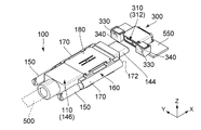
図1を参照すると、本発明の第1の実施の形態によるコネクタ100は、USB(Universal Serial Bus) Type−C規格に準拠しているプラグである。図1、並びに図4乃至図6を参照すると、本実施の形態のコネクタ100は、所定方向において前端102を有していると共に、所定方向に沿って第1接続対象物300及び第2接続対象物400の2つの接続対象物と選択的に接続可能なものである。本実施の形態において所定方向は、X方向である。また、本実施の形態において、+X方向が前方向であり、−X方向が後方向である。
First Embodiment
Referring to FIG. 1, the
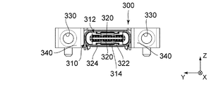
図4、図5、図8乃至図10に示されるように、本実施の形態において、第1接続対象物300は、コネクタ100と接続可能な相手側コネクタであり、具体的には、USB Type−C規格に準拠しているレセプタクルである。図8に示されるように、第1接続対象物300は、回路基板550上に搭載固定されるものであり、第1嵌合部310と、2つの雌ネジ部330と、2つの雌ネジ座面340とを備えている。換言すると、本実施の形態の第1接続対象物300は、雌ネジ部330を有するレセプタクルであり、第1嵌合部310は、受容部312を有している。図10に示されるように、受容部312は、所定方向において奥壁314を有している。第1嵌合部310は、所定方向と直交する横方向において、雌ネジ部330の間に位置している。本実施の形態において、横方向はY方向である。図10に示されるように、詳しくは、第1嵌合部310は、相手側コンタクト320と、相手側コンタクト320を保持する相手側保持部材322と、相手側保持部材322を覆う相手側シェル324とを備えている。
As shown in FIG. 4, FIG. 5, and FIG. 8 to FIG. 10, in the present embodiment, the
図8及び図11から理解されるように、第2接続対象物400は、第1嵌合部310に対応する構造を有する第2嵌合部430を備えているが、雌ネジ部330は有していない。図7、図11及び図12に示されるように、本実施の形態の第2接続対象物400は、相手側コネクタ420を電子機器(図示せず)の筐体410内に配置したものである。図8及び図11から理解されるように、相手側コネクタ420は、第1接続対象物300に対応する構造を有している。具体的には、相手側コネクタ420は、USB Type−C規格に準拠しているレセプタクルであって、雌ネジ部330を有しないレセプタクルである。図12に示されるように、相手側コネクタ420は、上述した第2嵌合部430を有している。また、第2嵌合部430は、所定方向において奥壁450を有する受容部440を有している。
As understood from FIGS. 8 and 11, the
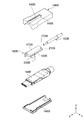
図1乃至図3に示されるように、コネクタ100は、コネクタ本体110と、2つの雄ネジ部材150と、ネジ保持部材160とを備えている。
As shown in FIGS. 1 to 3, the
図2に示されるように、本実施の形態のコネクタ本体110は、横方向おいて、2つの雄ネジ部材150の間に位置している。コネクタ本体110は、コンタクト140と、保持部材142と、シェル144と、フード146とを備えている。図2及び図10から理解されるように、コンタクト140は、コネクタ100と第1接続対象物300とが接続した際に相手側コンタクト320と接触するものである。図2に示されるように、保持部材142は、コンタクト140を保持している。シェル144は、保持部材142を覆っている。図1から理解されるように、シェル144の後端は、フード146内に位置している。フード146の中には、ケーブル500とコンタクト140とを接続する中継基板(図示せず)などが収容されている。中継基板(図示せず)に接続されたケーブル500は、フード146から後方に延びる。
As shown in FIG. 2, the
図1に示されるように、コネクタ本体110の先端112は、コネクタ100の前端102を構成している。図4及び図7から理解されるように、コネクタ本体110は、所定方向に沿って第1嵌合部310及び第2嵌合部430と選択的に嵌合可能なものである。図4及び図5から理解されるように、コネクタ100が第1接続対象物300と接続しているとき、コネクタ本体110は第1嵌合部310の受容部312に部分的に受容されている。
As shown in FIG. 1, the
図3及び図17に示されるように、コネクタ本体110の上面114上及び下面116上の夫々には、スライド面118と、前側対向部120と、後側対向部122とが設けられている。但し、本発明はこれに限定されるわけではなく、スライド面118と、前側対向部120と、後側対向部122は、コネクタ本体110の上面114上及び下面116上の一方に設けられていてもよい。スライド面118は、所定方向において、前側対向部120と後側対向部122との間に位置している。前側対向部120は、スライド面118の前側において上下方向に立つ壁である。後側対向部122は、スライド面118の後側において上下方向に立つ壁である。本実施の形態において、スライド面118と、前側対向部120と、後側対向部122は、フード146に形成されている。また、前側対向部120は、後述するように、被規制部として機能する。
As shown in FIGS. 3 and 17, on the
更に、コネクタ本体110の上面114上及び下面116上の夫々には、前側凹部130と後側凹部132とが所定方向に互いに離れて設けられている。但し、本発明はこれに限定されるわけではなく、前側凹部130と後側凹部132は、コネクタ本体110の上面114上及び下面116上の一方に設けられていてもよい。本実施の形態において、前側凹部130と後側凹部132は、フード146のスライド面118上に形成されている。
Further, on the
図1及び図3から理解されるように、ネジ保持部材160は、コネクタ本体110に取り付けられている。図1並びに図13乃至図16に示されるように、ネジ保持部材160は、所定方向に沿って前側所定位置と後側所定位置との間でコネクタ本体110に対して相対的に移動可能である。
As understood from FIGS. 1 and 3, the
詳しくは、図3に示されるように、本実施の形態のネジ保持部材160は、2つのネジ収容部材170と、上側可動部材180と、下側可動部材190とを備えている。図1及び図3から理解されるように、上側可動部材180及び下側可動部材190の夫々は、横方向において2つのネジ収容部材170を連結している。本実施の形態の上側可動部材180及び下側可動部材190の夫々は、主として板状の形状を有しており、横方向の両端に圧入片182,192が設けられている。ネジ収容部材170には、圧入溝178が設けられている。圧入片182,192を圧入溝178に圧入することにより、2つのネジ収容部材170は、上側可動部材180及び下側可動部材190により連結されている。図1及び図13から理解されるように、所定方向及び横方向の双方と直交する上下方向において、上側可動部材180と下側可動部材190とは、コネクタ本体110を挟んでいる。本実施の形態において、上下方向は、Z方向である。また、+Z方向は上方向であり、−Z方向は下方向である。上側可動部材180は、コネクタ本体110の上面114上を所定方向に移動するものであり、下側可動部材190は、コネクタ本体110の下面116上を所定方向に移動するものである。図1、図3、図13及び図17から理解されるように、具体的には、上側可動部材180は、上側のスライド面118上を所定方向にスライドするものであり、下側可動部材190は、下側のスライド面118上を所定方向にスライドするものである。
Specifically, as shown in FIG. 3, the
図3に示されるように、上側可動部材180及び下側可動部材190の夫々は、前側突当部200と後側突当部210とを有している。但し、本発明はこれに限定されるわけではなく、前側突当部200と後側突当部210は、上側可動部材180及び下側可動部材190の一方に設けられていてもよい。図1、図13乃至図16から理解されるように、本実施の形態において前側突当部200は、所定方向において前側対向部120と対向しており、且つ、前側対向部120の後側に位置している。また、後側突当部210は、所定方向において後側対向部122と対向しており、且つ、後側対向部122の前側に位置している。これにより、前側対向部120は、前側突当部200が所定方向において前側対向部120を越えて前方に移動することを規制しており、後側対向部122は、後側突当部210が所定方向において後側対向部122を越えて後方に移動することを規制している。
As shown in FIG. 3, each of the upper
このことから理解されるように、本実施の形態の前側突当部200は、前側対向部(被規制部)120に対する規制部として機能する。詳しくは、前側突当部200は、所定方向において前側対向部(被規制部)120の後側に配置されると共に所定方向において前側対向部(被規制部)120と対向しており、前側対向部(被規制部)120が所定方向において規制部を越えて後側に移動することを規制している。換言すると、本実施の形態のネジ保持部材160には、所定方向において被規制部の後側に配置されると共に所定方向において被規制部と対向する規制部が設けられている。この規制部は、被規制部が所定方向において規制部を越えて後側に移動することを規制している。
As understood from this, the
更に、図3に示されるように、上側可動部材180及び下側可動部材190の夫々は、バネ部225と位置決め突起220を有している。但し、本発明はこれに限定されるわけではなく、バネ部225及び位置決め突起220は、上側可動部材180及び下側可動部材190の一方に設けられていてもよい。バネ部225は、弾性変形可能なものであり、位置決め突起220を支持している。位置決め突起220は、上下方向において内側に向かって突出している。位置決め突起220は、バネ部225の弾性を利用して上下方向に移動可能である。図18及び図19から理解されるように、本実施の形態の位置決め突起220は、バネ部225の弾性を利用して前側凹部130と後側凹部132との間を乗り越えて、前側凹部130と後側凹部132のいずれかに収容されて、所定方向においてネジ保持部材160をコネクタ本体110に対して相対的に位置決めする。
Furthermore, as shown in FIG. 3, each of the upper
図1、図13、図14及び図18から理解されるように、本実施の形態において、ネジ保持部材160が前側所定位置に位置しているとき、前側突当部200が前側対向部120に突き当たっていると共に位置決め突起220が前側凹部130に収容されている。換言すると、前側突当部200と前側対向部120、並びに、位置決め突起220と前側凹部130とが前側所定位置を規定している。但し、本発明はこれに限定されるわけではなく、前側突当部200と前側対向部120のみで前側所定位置を規定してもよいし、位置決め突起220と前側凹部130のみで前側所定位置を規定してもよい。更に、他の手段により、前側所定位置を規定してもよい。
As understood from FIG. 1, FIG. 13, FIG. 14 and FIG. 18, in the present embodiment, when the
図15、図16及び図19から理解されるように、本実施の形態において、ネジ保持部材160が後側所定位置に位置しているとき、後側突当部210が後側対向部122に突き当たっていると共に位置決め突起220が後側凹部132に収容されている。換言すると、後側突当部210と後側対向部122、並びに、位置決め突起220と後側凹部132とが後側所定位置を規定している。但し、本発明はこれに限定されるわけではなく、後側突当部210と後側対向部122のみで後側所定位置を規定してもよいし、位置決め突起220と後側凹部132のみで後側所定位置を規定してもよい。更に、他の手段により、後側所定位置を規定してもよい。
As understood from FIGS. 15, 16 and 19, in the present embodiment, when the
図1、図3、図21及び図22から理解されるように、ネジ収容部材170は、夫々、雄ネジ部材150を部分的に収容していると共に、雄ネジ部材150を保持している。図20に示されるように、詳しくは、ネジ収容部材170には、雄ネジ座面172と、収容部174と、凸部176とが設けられている。図4及び図5から理解されるように、雄ネジ座面172は、雄ネジ部材150が雌ネジ部330に接続されたときに雌ネジ座面340に接触する面である。図20に示されるように、本実施の形態の雄ネジ座面172は、ネジ収容部材170の前面である。収容部174は、所定方向に延びており、雄ネジ部材150を部分的に収容している。凸部176は、所定方向と直交する面内において収容部174内に突出している。
As understood from FIGS. 1, 3, 21 and 22, the
図1及び図14から理解されるように、本実施の形態において、雄ネジ部材150は、所定方向に沿ってネジ保持部材160に対して相対的に移動可能である。図3に示されるように、詳しくは、雄ネジ部材150には、所定方向と直交する方向に凹んだ凹部152が形成されている。図21及び図22に示されるように、雄ネジ部材150が収容部174に部分的に収容された状態において、凸部176は凹部152内に収容されている。ここで、所定方向において、凹部152のサイズは、凸部176のサイズよりも遥かに大きい。そのため、図1及び図14に示されるように、雄ネジ部材150は、所定方向に沿ってネジ保持部材160に対して相対的に移動することができる。これにより、雄ネジ部材150のトータルの移動量を増やすことができる。
As understood from FIGS. 1 and 14, in the present embodiment, the
本実施の形態において、前側所定位置と後側所定位置とは次の条件を満たすように設定されている:1)ネジ保持部材160が前側所定位置にあるとき、雄ネジ部材150が雌ネジ部330に接続されると共に雄ネジ座面172が雌ネジ座面340に接触した状態においてコネクタ本体110の先端112が第1嵌合部310の奥壁314に対向する一方で奥壁314に達しない;及び、2)ネジ保持部材160が後側所定位置にあるとき、コネクタ100が第2接続対象物400と接続している状態においてコネクタ本体110の先端112が第2嵌合部430の奥壁450に達することが可能である。換言すると、コネクタ100が第2接続対象物400と接続している状態においてコネクタ本体110の先端112が第2嵌合部430の奥壁450に達しているとき、ネジ保持部材160が後側所定位置に位置していてもよいし、後側所定位置に達しておらず後側所定位置の前側に位置していてもよい。
In the present embodiment, the front side predetermined position and the rear side predetermined position are set to satisfy the following conditions: 1) When the
条件1)において、コネクタ本体110の先端112と第1嵌合部310の奥壁314との距離は、コネクタ100や第1接続対象物300における公差が最大になったときにコネクタ本体110の先端112が第1嵌合部310の奥壁314にわずかに達しないように設定する。これにより、コネクタ100や第1接続対象物300における公差が最大になったとしてもコネクタ本体110の先端112から第1嵌合部310の奥壁314に対して不要なストレスが加わってしまうことを避けることができる。
In condition 1), the distance between the
条件2)が設定されていることから、コネクタ本体110の先端112が第2嵌合部430の奥壁450まで確実に達することができる。即ち、コネクタ100と第2接続対象物400に含まれる相手側コネクタ420(レセプタクル)とを適切に接続することができる。
Since condition 2) is set, the
上述したように、本実施の形態のコネクタ100には規制部と被規制部とが設けられていることから、雄ネジ部材150が雌ネジ部330に接続された状態において、コネクタ100に接続されたケーブル500を後方に引っ張ったとしても、コネクタ本体110がネジ保持部材160から抜けてしまうことを防止することができる。
As described above, since the restricting portion and the restricted portion are provided in the
(第2の実施の形態)
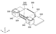
図23を参照すると、本発明の第2の実施の形態によるコネクタ100Aは、USB Type−C規格に準拠しているプラグである。図23に示されるように、本実施の形態のコネクタ100Aは、所定方向において前端102Aを有している。図23のコネクタ100Aは、所定方向に沿って、図26の第1接続対象物300Aにも接続可能であり、また、図11の第2接続対象物400にも接続可能である。即ち、本実施の形態のコネクタ100Aは、所定方向に沿って第1接続対象物300A及び第2接続対象物400の2つの接続対象物と選択的に接続可能なものである。このうち、第2接続対象物400は第1の実施の形態のものと同じであるので説明を省略する。本実施の形態においても所定方向は、X方向である。また、本実施の形態において、+X方向が前方向であり、−X方向が後方向である。更に、本実施の形態においても、横方向はY方向であり、上下方向はZ方向である。加えて、+Z方向は上方向であり、−Z方向は下方向である。
Second Embodiment
Referring to FIG. 23, the
図26及び図27に示されるように、本実施の形態において、第1接続対象物300Aは、コネクタ100Aと接続可能な相手側コネクタであり、具体的には、USB Type−C規格に準拠しているレセプタクルである。図26に示されるように、第1接続対象物300Aは、回路基板550A上に搭載固定されるものである。図27に示されるように、第1接続対象物300Aは、第1嵌合部310Aと、1つの雌ネジ部330Aと、1つの雌ネジ座面340Aとを備えている。換言すると、本実施の形態の第1接続対象物300Aは、雌ネジ部330Aを有するレセプタクルである。第1嵌合部310Aは、受容部312Aを有している。受容部312Aは、所定方向において奥壁314Aを有している。雌ネジ部330Aは、第1嵌合部310Aの上側に位置している。詳しくは、第1嵌合部310Aは、相手側コンタクト320Aと、相手側コンタクト320Aを保持する相手側保持部材322Aと、相手側保持部材322Aを覆う相手側シェル324Aとを備えている。
As shown in FIGS. 26 and 27, in the present embodiment, the
図23に示されるように、コネクタ100Aは、コネクタ本体110Aと、1つの雄ネジ部材150Aと、ネジ保持部材160Aとを備えている。雄ネジ部材150Aは、上下方向において、コネクタ本体110Aの上側に位置している。
As shown in FIG. 23, the
図24に示されるように、コネクタ本体110Aは、第1の実施の形態と同様に、コンタクト140Aと、コンタクト140Aを保持する保持部材142Aと、保持部材142Aを覆うシェル144Aと、フード146Aとを備えている。これらについての説明は省略する。
As shown in FIG. 24, as in the first embodiment, the
図23及び図28に示されるように、コネクタ本体110Aの先端112Aは、コネクタ100Aの前端102Aを構成している。コネクタ本体110Aは、所定方向に沿って図26の第1嵌合部310A及び図11の第2嵌合部430と選択的に嵌合可能なものである。図26及び図27から理解されるように、コネクタ100Aが第1接続対象物300Aと接続しているとき、コネクタ本体110Aは第1嵌合部310Aの受容部312Aに部分的に受容されている。
As shown in FIGS. 23 and 28, the
図25に示されるように、コネクタ本体110Aの上面114A上には、2つのスライド面118Aと2組の前側対向部120Aと後側対向部122Aとが設けられている。但し、本発明はこれに限定されるわけではなく、コネクタ本体110Aの上面114A上には、1つのスライド面118Aと1組の前側対向部120Aと後側対向部122Aのみが設けられていてもよい。スライド面118Aは、所定方向において前側対向部120Aと後側対向部122Aとの間に位置している。前側対向部120Aは、スライド面118Aの前側において上下方向に立つ壁である。後側対向部122Aは、スライド面118Aの後側において上下方向に立つ壁である。本実施の形態において、スライド面118Aと前側対向部120Aと後側対向部122Aは、フード146Aに形成されている。前側対向部120Aは、後述するように、被規制部として機能する。
As shown in FIG. 25, on the
図25、図29及び図30から理解されるように、コネクタ本体110Aは、所定方向に延びる2組の溝124Aと、1組のバネ部136Aと、1組の位置決め突起134Aとを有している。但し、本発明はこれに限定されるわけではなく、コネクタ本体110Aは、1組の溝124Aと1組のバネ部136Aと1組の位置決め突起134Aのみを有していてもよい。バネ部136Aは、前側の溝124Aに夫々対応して設けられている。バネ部136Aは、弾性変形可能なものであり、位置決め突起134Aを支持している。位置決め突起134Aは、横方向において溝124A内に突出している。位置決め突起134Aは、バネ部136Aの弾性を利用して横方向に移動可能である。本実施の形態において、溝124A及び位置決め突起134Aは、フード146Aに形成されている。
As understood from FIGS. 25, 29 and 30, the
図23及び図28に示されるように、ネジ保持部材160Aは、コネクタ本体110Aに取り付けられており、所定方向に沿って前側所定位置と後側所定位置との間でコネクタ本体110Aに対して相対的に移動可能である。
As shown in FIGS. 23 and 28,
図25に示されるように、詳しくは、本実施の形態のネジ保持部材160Aは、上側収容部材170Aと、2つの可動部材180Aと、下側プレート190Aとを備えている。図29及び図30に示されるように、可動部材180Aは、上述した溝124A及び位置決め突起134Aと対応するものである。ネジ保持部材160Aは、1つのみの可動部材180Aを有していてもよい。図23乃至図25から理解されるように、上側収容部材170Aは、コネクタ本体110Aの上側に位置しており、雄ネジ部材150Aを部分的に収容している。雄ネジ部材150Aの収容構造は、上述した第1の実施の形態の場合と同じである。
As shown in FIG. 25, in detail, the
図25、図29及び図30から理解されるように、可動部材180Aの夫々は、所定方向に移動可能となるようにコネクタ本体110Aに保持されている。図25に示されるように、可動部材180Aの夫々は、上側収容部材170Aを取り付けられる上部182Aと、上下方向において上部182Aから下方に向かって延びる側部186Aとを有している。本実施の形態においては、上部182Aに突起184Aが形成されており、上側収容部材170Aには孔172Aが形成されている。図23及び図25から理解されるように、上部182Aの突起184Aを上側収容部材170Aの孔172Aに挿入し、突起184Aをカシメることにより、上側収容部材170Aは、可動部材180Aに固定されている。
As can be understood from FIGS. 25, 29, and 30, each of the
図23、図25及び図28から理解されるように、可動部材180Aの夫々の上部182Aは、スライド面118A上をスライドするものである。図25に示されるように、各上部182Aは、前側突当部200Aと後側突当部210Aとを有している。本実施の形態において、前側突当部200Aは上部182Aの前縁であり、後側突当部210Aは上部182Aの後縁である。図23、図25及び図28から理解されるように、前側突当部200Aは、所定方向において前側対向部120Aと対向しており、且つ、前側対向部120Aの後側に位置している。また、後側突当部210Aは、所定方向において後側対向部122Aと対向しており、且つ、後側対向部122Aの前側に位置している。これにより、前側対向部120Aは、前側突当部200Aが所定方向において前側対向部120Aを越えて前方に移動することを規制しており、後側対向部122Aは、後側突当部210Aが所定方向において後側対向部122Aを越えて後方に移動することを規制している。
As can be understood from FIGS. 23, 25 and 28, the
このことから理解されるように、本実施の形態の前側突当部200Aは、前側対向部(被規制部)120Aに対する規制部として機能する。この規制部は、被規制部が所定方向において規制部を越えて後側に移動することを規制している。
As understood from this, the
更に、各可動部材180Aの側部186Aは、コネクタ本体110Aの溝124A内に少なくとも部分的に収容されている。側部186Aの下端は、コネクタ本体110Aの下方に突出しており、下側プレート190Aにより連結されている。
Further, the
図25に示されるように、側部186Aの夫々には、被位置決め部188Aが設けられている。図29及び図30から理解されるように、可動部材180Aが所定方向に沿って移動する際、被位置決め部188Aはバネ部136Aに支持された位置決め突起134Aを乗り越えるものであり、所定方向において被位置決め部188Aが位置決め突起134Aの前方又は後方に位置することにより、可動部材180Aの所定方向における位置決めがなされる。
As shown in FIG. 25, each of the
図23、図25及び図29から理解されるように本実施の形態において、ネジ保持部材160Aが前側所定位置に位置しているとき、前側突当部200Aが前側対向部120Aに突き当たっていると共に位置決め突起134Aが被位置決め部188Aの後方に位置している。換言すると、前側突当部200Aと前側対向部120A、並びに、位置決め突起134Aと被位置決め部188Aとが前側所定位置を規定している。但し、本発明はこれに限定されるわけではなく、前側突当部200Aと前側対向部120Aのみで前側所定位置を規定してもよいし、位置決め突起134Aと被位置決め部188Aのみで前側所定位置を規定してもよい。更に、他の手段により、前側所定位置を規定してもよい。
As understood from FIG. 23, FIG. 25 and FIG. 29, in the present embodiment, when the
図25、図28及び図30から理解されるように、本実施の形態において、ネジ保持部材160Aが後側所定位置に位置しているとき、後側突当部210Aが後側対向部122Aに突き当たっていると共に位置決め突起134Aが被位置決め部188Aの前方に位置している。換言すると、後側突当部210Aと後側対向部122A、並びに、位置決め突起134Aと被位置決め部188Aとが後側所定位置を規定している。但し、本発明はこれに限定されるわけではなく、後側突当部210Aと後側対向部122Aのみで後側所定位置を規定してもよいし、位置決め突起134Aと被位置決め部188Aのみで後側所定位置を規定してもよい。更に、他の手段により、後側所定位置を規定してもよい。
As understood from FIGS. 25, 28 and 30, in the present embodiment, when the
本実施の形態において、前側所定位置と後側所定位置とは、第1の実施の形態において掲げた条件1)及び条件2)を満たすように設定されている。従って、本実施の形態においても、第1の実施の形態と同様の効果を得ることができる。 In the present embodiment, the front side predetermined position and the rear side predetermined position are set so as to satisfy the conditions 1) and 2) mentioned in the first embodiment. Therefore, also in this embodiment, the same effect as that of the first embodiment can be obtained.
(第3の実施の形態)
図31を参照すると、本発明の第3の実施の形態によるコネクタ100Bは、上述した図23の第2の実施の形態のコネクタ100Aの変形例であり、第2の実施の形態のコネクタ100Aと同様の接続対象物と接続されるものである。従って、以下においては、上述した第2の実施の形態のコネクタ100Aと共通する点については説明を省略する。なお、本実施の形態において、所定方向、横方向及び上下方向は、夫々、X方向、Y方向及びZ方向とする。また、本実施の形態において、+X方向は前方向であり、−X方向は後方向である。更に、本実施の形態において、+Z方向は上方向であり、−Z方向は下方向である。
Third Embodiment
Referring to FIG. 31, the
図31乃至図33から理解されるように、コネクタ100Bは、コネクタ本体110Bと、1つの雄ネジ部材150Bと、ネジ保持部材160Bとを備えている。雄ネジ部材150Bは、上下方向において、コネクタ本体110Bの上側に位置している。
As understood from FIGS. 31 to 33, the
図32に示されるように、コネクタ本体110Bは、第1の実施の形態と同様に、コンタクト140Bと、コンタクト140Bを保持する保持部材142Bと、保持部材142Bを覆うシェル144Bと、フード146Bとを備えている。コンタクト140B、保持部材142B及びシェル144Bについての説明は省略する。
As shown in FIG. 32, as in the first embodiment, the connector main 110B includes a
図33に示されるように、図示されたフード146Bは、上側部と下側部の2体からなる。上側のフード146Bには、スロット148Bが形成されている。スロット148Bは後縁149Bを有している。図35に示されるように、スロット148Bの前端の両横には、前側対向部120Bが形成されており、スロット148Bの後縁149B近傍には、後側対向部122Bが形成されている。本実施の形態の前側対向部120B及び後側対向部122Bは、フード146Bの内側に設けられている。即ち、本実施の形態において、前側対向部120Bと後側対向部122Bは、コネクタ本体110Bの内部に設けられている。
As shown in FIG. 33, the illustrated
図31乃至図33から理解されるように、本実施の形態のネジ保持部材160Bは、コネクタ本体110Bに部分的に収容された状態で取り付けられている。図31、図37及び図38から理解されるように、ネジ保持部材160Bは、所定方向に沿って前側所定位置と後側所定位置との間でコネクタ本体110Bに対して相対的に移動可能である。
As understood from FIGS. 31 to 33, the
図33及び図36に示されるように、詳しくは、本実施の形態のネジ保持部材160Bは、上側収容部170Bと可動部180Bとを有している。本実施の形態の可動部180Bと上側収容部170Bとは一体形成されている。図31及び図33から理解されるように、可動部180Bは、所定方向に移動可能となるようにコネクタ本体110B内に収容されている。図36に示されるように、可動部180Bには、前側突当部200Bと後側突当部210Bとが設けられている。本実施の形態において、前側突当部200Bは可動部180Bの前縁であり、後側突当部210Bは可動部180Bの後縁である。図37及び図38に示されるように、前側突当部200Bは、所定方向において前側対向部120Bと対向しており、且つ、前側対向部120Bの後側に位置している。また、後側突当部210Bは、所定方向において後側対向部122Bと対向しており、且つ、後側対向部122Bの前側に位置している。これにより、前側対向部120Bは、前側突当部200Bが所定方向において前側対向部120Bを越えて前方に移動することを規制しており、後側対向部122Bは、後側突当部210Bが所定方向において後側対向部122Bを越えて後方に移動することを規制している。このことから理解されるように、本実施の形態の前側突当部200Bは、前側対向部(被規制部)120Bに対する規制部として機能する。
As shown in FIGS. 33 and 36, in detail, the
図31及び図33から理解されるように、上側収容部170Bは、可動部180B上に設けられており、スロット148Bを通してコネクタ本体110B外に露出している。これにより、上側収容部170Bは、コネクタ本体110Bの上側に位置している。図31に示されるように、上側収容部170Bは、雄ネジ部材150Bを部分的に収容している。雄ネジ部材150Bの収容構造は、上述した第1の実施の形態のネジ収容部材の場合と同じである。図33及び図36に示されるように、上側収容部170Bは、後端部172Bを有している。図31及び図33から理解されるように、スロット148Bの後縁149Bは、所定方向において上側収容部170Bの後端部172Bと対向していると共に後端部172Bの後側に位置している。これにより、スロット148Bの後縁149Bは、上側収容部170Bの後端部172Bがスロット148Bの後縁149Bを越えて後方に移動することを規制している。
As understood from FIGS. 31 and 33, the
図37から理解されるように、本実施の形態において、ネジ保持部材160Bが前側所定位置に位置しているとき、前側突当部200Bが前側対向部120Bに突き当たっている。換言すると、前側突当部200Bと前側対向部120Bとが前側所定位置を規定している。但し、本発明はこれに限定されるわけではなく、他の手段により、前側所定位置を規定してもよい。
As understood from FIG. 37, in the present embodiment, when the
図34及び図38から理解されるように、本実施の形態において、ネジ保持部材160Bが後側所定位置に位置しているとき、後側突当部210Bが後側対向部122Bに突き当たっていると共に上側収容部170Bの後端部172Bがスロット148Bの後縁149Bに突き当たっている。換言すると、後側突当部210Bと後側対向部122B、並びに、上側収容部170Bの後端部172Bとスロット148Bの後縁149Bとが後側所定位置を規定している。但し、本発明はこれに限定されるわけではなく、後側突当部210Bと後側対向部122Bのみで後側所定位置を規定してもよいし、上側収容部170Bの後端部172Bとスロット148Bの後縁149Bのみで後側所定位置を規定してもよい。更に、他の手段により、後側所定位置を規定してもよい。
As understood from FIGS. 34 and 38, in the present embodiment, when the
本実施の形態において、前側所定位置と後側所定位置とは、第1の実施の形態において掲げた条件1)及び条件2)を満たすように設定されている。従って、本実施の形態においても、第1の実施の形態と同様の効果を得ることができる。 In the present embodiment, the front side predetermined position and the rear side predetermined position are set so as to satisfy the conditions 1) and 2) mentioned in the first embodiment. Therefore, also in this embodiment, the same effect as that of the first embodiment can be obtained.
(第4の実施の形態)
図39を参照すると、本発明の第4の実施の形態によるコネクタ100Cは、上述した図1の第1の実施の形態のコネクタ100の変形例であり、第1の実施の形態のコネクタ100と同様の接続対象物と接続されるものである。従って、以下においては、上述した第1の実施の形態のコネクタ100と共通する点については説明を省略する。なお、本実施の形態において、所定方向、横方向及び上下方向は、夫々、X方向、Y方向及びZ方向とする。また、本実施の形態において、+X方向は前方向であり、−X方向は後方向である。更に、本実施の形態において、+Z方向は上方向であり、−Z方向は下方向である。
Fourth Embodiment
Referring to FIG. 39, the
図39乃至図43に示されるように、コネクタ100Cは、コネクタ本体110Cと、2つの雄ネジ部材150Cと、ネジ保持部材160Cとを備えている。本実施の形態のコネクタ本体110Cは、横方向おいて、2つの雄ネジ部材150Cの間に位置している。図41に示されるように、コネクタ本体110Cは、第1の実施の形態と同様に、コンタクト140Cと、コンタクト140Cを保持する保持部材142Cと、保持部材142Cを覆うシェル144Cと、フード146Cとを備えている。これらについての説明は省略する。
As shown in FIGS. 39 to 43, the
図42、図44及び図46から理解されるように、コネクタ本体110Cの上面114C上及び下面116C上の夫々には、前側対向部120Cと後側対向部122Cとが設けられている。但し、本発明はこれに限定されるわけではなく、前側対向部120Cと後側対向部122Cは、コネクタ本体110Cの上面114C上及び下面116C上の一方に設けられていてもよい。本実施の形態において、前側対向部120Cと後側対向部122Cは、フード146Cに形成されている。本実施の形態において、前側対向部120Cは、フード146Cの前端に位置すると共に上下方向に立つ壁であり、後側対向部122Cは、上下方向に突出した突起である。前側対向部120Cは、後述するように、被規制部として機能する。
As understood from FIGS. 42, 44 and 46, the
更に、コネクタ本体110Cの上面114C上及び下面116C上の夫々には、前側凹部130Cと後側凹部132Cとが所定方向に互いに離れて設けられている。但し、本発明はこれに限定されるわけではなく、前側凹部130Cと後側凹部132Cは、コネクタ本体110Cの上面114C上及び下面116C上の一方に設けられていてもよい。本実施の形態において、前側凹部130Cと後側凹部132Cは、フード146Cに形成されている。
Further, on the
ネジ保持部材160Cは、コネクタ本体110Cに取り付けられており、所定方向に沿って前側所定位置と後側所定位置との間でコネクタ本体110Cに対して相対的に移動可能である。
The
図42に示されるように、詳しくは、本実施の形態のネジ保持部材160Cには、2つの側部収容部170Cと、中央収容部180Cとが形成されている。側部収容部170C及び中央収容部180Cは、いずれも所定方向においてネジ保持部材160Cを貫通している。図39及び図42から理解されるように、側部収容部170Cは、夫々、雄ネジ部材150Cを部分的に収容している。雄ネジ部材150Cの収容構造は、上述した第1の実施の形態のネジ収容部材の場合と同じである。中央収容部180Cは、横方向において側部収容部170Cの間に位置していると共に、所定方向において移動可能となるようにコネクタ本体110Cを部分的に収容している。
As shown in FIG. 42, in detail, in the
図42、図44及び図46から理解されるように、ネジ保持部材160Cには、2組の前側突当部200C及び後側突当部210Cが設けられている。各組の前側突当部200C及び後側突当部210Cは、中央収容部180Cの縁であってネジ保持部材160Cの上下の前縁及び後縁である。但し、本発明はこれに限定されるわけではなく、前側突当部200Cと後側突当部210Cは、ネジ保持部材160Cの上側のみ又は下側のみに設けられていてもよい。前側突当部200Cは、所定方向において前側対向部120Cと対向しており、且つ、前側対向部120Cの後側に位置している。また、後側突当部210Cは、所定方向において後側対向部122Cと対向しており、且つ、後側対向部122Cの前側に位置している。これにより、前側対向部120Cは、前側突当部200Cが所定方向において前側対向部120Cを越えて前方に移動することを規制しており、後側対向部122Cは、後側突当部210Cが所定方向において後側対向部122Cを越えて後方に移動することを規制している。このことから理解されるように、本実施の形態の前側突当部200Cは、前側対向部(被規制部)120Cに対する規制部として機能する。
As understood from FIGS. 42, 44 and 46, the
更に、ネジ保持部材160Cは、上側のバネ部225C及び位置決め突起220Cと下側のバネ部225C及び位置決め突起220Cとを有している。但し、本発明はこれに限定されるわけではなく、バネ部225C及び位置決め突起220Cは、上側及び下側の一方のみに設けられていてもよい。バネ部225Cは、弾性変形可能なものであり、位置決め突起220Cを支持している。位置決め突起220Cは、いずれも、上下方向において中央収容部180C内に向かって突出している。位置決め突起220Cは、バネ部225Cの弾性を利用して上下方向に移動可能である。本実施の形態の位置決め突起220Cは、バネ部225Cの弾性を利用して前側凹部130Cと後側凹部132Cとの間を乗り越えて、前側凹部130Cと後側凹部132Cのいずれかに収容されて、所定方向においてネジ保持部材160Cをコネクタ本体110Cに対して相対的に位置決めする。
Further, the
図39、図40、図43及び図44から理解されるように、本実施の形態において、ネジ保持部材160Cが前側所定位置に位置しているとき、前側突当部200Cが前側対向部120Cに突き当たっていると共に位置決め突起220Cが前側凹部130Cに収容されている。換言すると、前側突当部200Cと前側対向部120C、並びに、位置決め突起220Cと前側凹部130Cとが前側所定位置を規定している。但し、本発明はこれに限定されるわけではなく、前側突当部200Cと前側対向部120Cのみで前側所定位置を規定してもよいし、位置決め突起220Cと前側凹部130Cのみで前側所定位置を規定してもよい。更に、他の手段により、前側所定位置を規定してもよい。
As understood from FIG. 39, FIG. 40, FIG. 43 and FIG. 44, in the present embodiment, when the
図45乃至図47から理解されるように、本実施の形態において、ネジ保持部材160Cが後側所定位置に位置しているとき、後側突当部210Cが後側対向部122Cに突き当たっていると共に位置決め突起220Cが後側凹部132Cに収容されている。換言すると、後側突当部210Cと後側対向部122C、並びに、位置決め突起220Cと後側凹部132Cとが後側所定位置を規定している。但し、本発明はこれに限定されるわけではなく、後側突当部210Cと後側対向部122Cのみで後側所定位置を規定してもよいし、位置決め突起220Cと後側凹部132Cのみで後側所定位置を規定してもよい。更に、他の手段により、後側所定位置を規定してもよい。
As understood from FIGS. 45 to 47, in the present embodiment, when the
本実施の形態において、前側所定位置と後側所定位置とは、第1の実施の形態において掲げた条件1)及び条件2)を満たすように設定されている。従って、本実施の形態においても、第1の実施の形態と同様の効果を得ることができる。 In the present embodiment, the front side predetermined position and the rear side predetermined position are set so as to satisfy the conditions 1) and 2) mentioned in the first embodiment. Therefore, also in this embodiment, the same effect as that of the first embodiment can be obtained.
(第5の実施の形態)
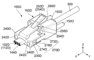
図48を参照すると、本発明の第5の実施の形態によるコネクタ100Dは、上述した図1の第1の実施の形態のコネクタ100の変形例であり、第1の実施の形態のコネクタ100と同様の接続対象物と接続されるものである。従って、以下においては、上述した第1の実施の形態のコネクタ100と共通する点については説明を省略する。なお、本実施の形態において、所定方向、横方向及び上下方向は、夫々、X方向、Y方向及びZ方向とする。また、本実施の形態において、+X方向は前方向であり、−X方向は後方向である。更に、本実施の形態において、+Z方向は上方向であり、−Z方向は下方向である。
Fifth Embodiment
Referring to FIG. 48, the
図48乃至図52並びに図54に示されるように、コネクタ100Dは、コネクタ本体110Dと、2つの雄ネジ部材150Dと、ネジ保持部材160Dとを備えている。本実施の形態のコネクタ本体110Dは、横方向おいて、2つの雄ネジ部材150Dの間に位置している。図49及び図50に示されるように、コネクタ本体110Dは、第1の実施の形態と同様に、コンタクト140Dと、コンタクト140Dを保持する保持部材142Dと、保持部材142Dを覆うシェル144Dと、フード146Dとを備えている。これらについての説明は省略する。
As shown in FIGS. 48 to 52 and 54, the
図48、図49、図51及び図52から理解されるように、コネクタ本体110Dには、2つのガイド部230Dと、2つの前壁部240Dと、操作部(レバー)250Dと、位置決め凹部258Dとが設けられている。位置決め凹部258Dは、フード146Dの下面上に形成されている。
As understood from FIGS. 48, 49, 51 and 52, the
ガイド部230Dの夫々は、所定方向に延びている。またガイド部230Dは、横方向においてコネクタ本体110Dの両端に位置している。即ち、ガイド部230Dは、横方向において互いに離れて位置している。前壁部240Dは、所定方向において、ガイド部230Dの前側に夫々位置している。前壁部240Dは、横方向において互いに離れて位置している。前壁部240Dの夫々には、所定方向において貫通する貫通孔242Dが形成されている。前壁部240Dは、後述するように、被規制部として機能する。
Each of the
図48乃至図51に示されるように、操作部250Dは、フード146Dの前端近傍から上方に延びている。図51に示されるように、具体的には、コネクタ本体110Dの操作部250Dには、フード146Dの前端近傍から延びる幅広部252Dと、幅広部252Dから延びる幅狭部254Dとが形成されている。幅狭部254Dは、横方向において幅広部252Dよりサイズの小さいものである。幅広部252Dと幅狭部254Dとの境界には、被受部256Dが形成されている。
As shown in FIGS. 48 to 51, the
図48及び図49から理解されるように、ネジ保持部材160Dは、コネクタ本体110Dに取り付けられており、所定方向に沿って前側所定位置と後側所定位置との間でコネクタ本体110Dに対して相対的に移動可能である。
As understood from FIGS. 48 and 49, the
図51に示されるように、本実施の形態のネジ保持部材160Dには、2つの側部収容部170Dと、中央収容部180Dとが形成されている。側部収容部170D及び中央収容部180Dは、いずれも所定方向においてネジ保持部材160Dを貫通している。図48、図49及び図51から理解されるように、側部収容部170Dは、夫々、雄ネジ部材150Dを部分的に収容している。雄ネジ部材150Dの収容構造は、上述した第1の実施の形態のネジ収容部材の場合と同じである。図51に示されるように、中央収容部180Dは、横方向において側部収容部170Dの間に位置している。図53及び図55に示されるように、中央収容部180Dは、所定方向において移動可能となるようにコネクタ本体110Dを部分的に収容している。
As shown in FIG. 51, in the
図51に示されるように、詳しくは、本実施の形態のネジ保持部材160Dには、後部260Dと2つの腕部270Dとが設けられている。中央収容部180Dは、後部260Dに設けられている。
As shown in FIG. 51, in detail, a
図52、図53及び図55から理解されるように、後部260Dには、下方向において中央収容部180Dの内側に向かって突出した位置決め突起262Dが設けられている。位置決め突起262Dは、コネクタ本体110Dの位置決め凹部258Dに収容されている。所定方向において、位置決め凹部258Dは、位置決め突起262Dよりも大きなサイズを有している。従って、位置決め突起262Dは、位置決め凹部258D内において移動することができる。その一方で、位置決め突起262Dは、位置決め凹部258Dを越えて後方に移動することはできない。即ち、位置決め凹部258Dは、所定方向において位置決め突起262Dが位置決め凹部258Dを越えて後方に移動することを規制している。
As understood from FIGS. 52, 53 and 55, the
図51に示されるように、ネジ保持部材160Dの後部260Dには、受部264Dと、所定方向において受部264Dから後方に延びるスロット266Dが設けられている。図48、図49及び図51から理解されるように、スロット266Dは、操作部250Dの幅狭部254Dを部分的に収容している。
As shown in FIG. 51, the
図48に示されるように、操作部250Dを操作していない状態においては、被受部256Dが受部264Dの前方に位置してネジ保持部材160Dの前方への移動を規制している。図48、図49及び図54から理解されるように、操作部250Dを操作して被受部256Dを上下方向に移動させると、被受部256Dによる受部264Dの規制が解除され、ネジ保持部材160Dが前方に移動可能となる。
As shown in FIG. 48, in a state where the
図51に示されるように、腕部270Dは、横方向において互いに離れて位置している。腕部270Dの夫々は、所定方向において後部260Dから前方に向かって延びている。側部収容部170Dは、対応する腕部270Dと後部260Dとに連続して形成されている。
As shown in FIG. 51, the
腕部270Dの夫々は、被ガイド部272Dと、被ガイド部272Dから前方に突出した突出部274Dとを有している。被ガイド部272Dは、コネクタ本体110Dのガイド部230Dに受容されており、所定方向における移動をガイドされている。被ガイド部272Dと突出部274Dとの境界には、所定方向において前方に向いている突当部278Dが設けられている。即ち、突当部278Dは、突出部274Dの後端の周囲に夫々位置している。突出部274Dの前端は、夫々、雄ネジ座面276Dとして機能している。
Each of the
図48及び図49から理解されるように、突出部274Dは、ネジ保持部材160Dのコネクタ本体110Dに対する相対的な移動により、夫々、貫通孔242Dを通して前方に突出可能である。図48及び図51から理解されるように、突当部278Dは、夫々、所定方向において前壁部240Dと対向すると共に前壁部240Dの後側に位置している。図49及び図54に示されるように、突当部278Dが前壁部240Dに突き当たることにより、突出部274Dの前壁部240Dからの最大突出量が規定されている。このことから理解されるように、本実施の形態の突当部278Dは、前壁部(被規制部)240Dに対する規制部として機能する。
As can be understood from FIGS. 48 and 49, the
図49、図54及び図55から理解されるように、本実施の形態において、ネジ保持部材160Dが前側所定位置に位置しているとき、突当部278Dが前壁部240Dに突き当たっている。換言すると、突当部278Dと前壁部240Dは前側所定位置を規定している。但し、本発明はこれに限定されるわけではなく、他の手段により、前側所定位置を規定してもよい。
As understood from FIGS. 49, 54 and 55, in the present embodiment, when the
図48及び図53から理解されるように、本実施の形態において、ネジ保持部材160Dが後側所定位置に位置しているとき、被受部256Dが受部264Dの前方に位置していると共に位置決め突起262Dが位置決め凹部258D内に位置している。換言すると、受部264Dと被受部256D、並びに、位置決め突起262Dと位置決め凹部258Dとが後側所定位置を規定している。但し、本発明はこれに限定されるわけではなく、他の手段により、後側所定位置を規定してもよい。
As understood from FIGS. 48 and 53, in the present embodiment, when
本実施の形態において、前側所定位置と後側所定位置とは、第1の実施の形態において掲げた条件1)及び条件2)を満たすように設定されている。従って、本実施の形態においても、第1の実施の形態と同様の効果を得ることができる。 In the present embodiment, the front side predetermined position and the rear side predetermined position are set so as to satisfy the conditions 1) and 2) mentioned in the first embodiment. Therefore, also in this embodiment, the same effect as that of the first embodiment can be obtained.
以上、本発明について、複数の実施の形態を掲げて具体的に説明してきたが、本発明はこれらに限定されるものではない。例えば、雄ネジ部材を1つのみ備えるコネクタにおいて、第1の実施の形態や第4の実施の形態、第5の実施の形態の概念を適用してもよい。逆に、雄ネジ部材を2つ備えるコネクタにおいて、第2の実施の形態や第3の実施の形態の概念を適用してもよい。 Although the present invention has been specifically described with reference to a plurality of embodiments, the present invention is not limited to these. For example, in the connector including only one male screw member, the concepts of the first embodiment, the fourth embodiment, and the fifth embodiment may be applied. Conversely, in the connector including two male screw members, the concepts of the second embodiment and the third embodiment may be applied.
100,100A,100B,100C,100D コネクタ
102,102A 前端
110,110A,110B,110C,110D コネクタ本体
112,112A 先端
114,114A,114C 上面
116,116C 下面
118,118A スライド面
120,120A,120B,120C 前側対向部
122,122A,122B,122C 後側対向部
124A 溝
130,130C 前側凹部
132,132C 後側凹部
134A 位置決め突起
136A バネ部
140,140A,140B,140C,140D コンタクト
142,142A,142B,142C,142D 保持部材
144,144A,144B,144C,144D シェル
146,146A,146B,146C,146D フード
148B スロット
149B 後縁
150,150A,150B,150C,150D 雄ネジ部材
152 凹部
160,160A,160B,160C,160D ネジ保持部材
170 ネジ収容部材
172 雄ネジ座面
174 収容部
176 凸部
178 圧入溝
170A 上側収容部材
172A 孔
170B 上側収容部
172B 後端部
170C,170D 側部収容部
180 上側可動部材
182 圧入片
180A 可動部材
182A 上部
184A 突起
186A 側部
188A 被位置決め部
180B 可動部
180C,180D 中央収容部
190 下側可動部材
192 圧入片
190A 下側プレート
200,200A,200B,200C 前側突当部
210,210A,210B,210C 後側突当部
220,220C 位置決め突起
225,225C バネ部
230D ガイド部
240D 前壁部
242D 貫通孔
250D 操作部(レバー)
252D 幅広部
254D 幅狭部
256D 被受部
258D 位置決め凹部
260D 後部
262D 位置決め突起
264D 受部
266D スロット
270D 腕部
272D 被ガイド部
274D 突出部
276D 雄ネジ座面
278D 突当部
300,300A 第1接続対象物
310,310A 第1嵌合部
312,312A 受容部
314,314A 奥壁
320,320A 相手側コンタクト
322,322A 相手側保持部材
324,324A 相手側シェル
330,330A 雌ネジ部
340,340A 雌ネジ座面
400 第2接続対象物
410 筐体
420 相手側コネクタ
430 第2嵌合部
440 受容部
450 奥壁
500 ケーブル
550,550A 回路基板
100, 100A, 100B, 100C, 100D connector 102, 102A front end 110, 110A, 110B, 110C, 110D connector main body 112, 112A tip 114, 114A, 114C upper surface 116, 116C lower surface 118, 118A sliding surface 120, 120A, 120B, 120B, 120C front facing portion 122, 122A, 122B, 122C rear facing portion 124A groove 130, 130C front concave portion 132, 132C rear concave portion 134A positioning projection 136A spring portion 140, 140A, 140B, 140C, 140D contacts 142, 142A, 142B, 142C, 142D Holding member 144, 144A, 144B, 144C, 144D Shell 146, 146A, 146B, 146C, 146D Hood 148B Slot 149B rear edge 150, 150A, 150B, 150C, 150D male screw member 152 recessed portion 160, 160A, 160B, 160C, 160D screw holding member 170 screw housing member 172 male screw seat surface 174 housing portion 176 convex portion 178 press fit groove 170A upper housing Member 172A hole 170B upper housing portion 172B rear end portion 170C, 170D side housing portion 180 upper movable member 182 press-fit piece 180A movable member 182A upper portion 184A protrusion 186A side portion 188A positioning portion 180B movable portion 180C, 180D central housing portion 190 lower Side movable member 192 Press-fit piece 190A Lower plate 200, 200A, 200B, 200C Front abutment part 210, 210A, 210B, 210C Rear abutment part 220, 220C Positioning projection 225, 225C Bar Part 230D guide portion 240D front wall portion 242D through hole 250D operation unit (lever)
252D
Claims (25)
前記第1接続対象物は、相手側コンタクトを有する第1嵌合部と、雌ネジ部と、雌ネジ座面とを備えており、
前記第2接続対象物は、前記第1嵌合部に対応する構造を有する第2嵌合部を備えており、
前記コネクタは、コネクタ本体と、雄ネジ部材と、ネジ保持部材とを備えており、
前記コネクタ本体は、前記所定方向に沿って前記第1嵌合部及び前記第2嵌合部と選択的に嵌合可能なものであり、
前記コネクタ本体は、前記コネクタと前記第1接続対象物とが接続した際に前記相手側コンタクトと接触するコンタクトを有しており、
前記ネジ保持部材は、前記雄ネジ部材を保持しており、
前記ネジ保持部材は、前記雄ネジ部材が前記雌ネジ部に接続されたときに前記雌ネジ座面に接触する雄ネジ座面を有しており、
前記ネジ保持部材は、前記コネクタ本体に取り付けられており、前記所定方向に沿って前記コネクタ本体に対して相対的に移動可能である
コネクタ。 A connector having a front end in a predetermined direction and selectively connectable to a first connection object and a second connection object along the predetermined direction,
The first connection object includes a first fitting portion having a mating contact, a female screw portion, and a female screw seat surface,
The second connection object includes a second fitting portion having a structure corresponding to the first fitting portion,
The connector includes a connector body, an external thread member, and a screw holding member.
The connector main body is selectively engageable with the first fitting portion and the second fitting portion along the predetermined direction,
The connector body has a contact that contacts the mating contact when the connector and the first connection object are connected,
The screw holding member holds the male screw member,
The screw holding member has a male screw seat surface that contacts the female screw seat surface when the male screw member is connected to the female screw portion,
The connector according to claim 1, wherein the screw holding member is attached to the connector body and is movable relative to the connector body along the predetermined direction.
前記雄ネジ部材は、前記所定方向に沿って前記ネジ保持部材に対して相対的に移動可能である
コネクタ。 The connector according to claim 1, wherein
The connector, wherein the male screw member is movable relative to the screw holding member along the predetermined direction.
前記ネジ保持部材には、前記所定方向に延びる収容部と、前記所定方向と直交する面内において前記収容部内に突出した凸部とが設けられており、
前記雄ネジ部材には、前記所定方向と直交する方向に凹んだ凹部が形成されており、
前記雄ネジ部材が前記収容部に部分的に収容される一方、前記凸部が前記凹部内に収容されている
コネクタ。 The connector according to claim 2, wherein
The screw holding member is provided with a housing portion extending in the predetermined direction, and a convex portion protruding into the housing portion in a plane orthogonal to the predetermined direction,
The male screw member is formed with a concave portion which is recessed in a direction orthogonal to the predetermined direction,
The connector in which the male screw member is partially housed in the housing portion, and the convex portion is housed in the concave portion.
前記コネクタ本体は、前記コネクタの前記前端を構成する先端を有しており、
前記ネジ保持部材は、前側所定位置と後側所定位置との間で前記所定方向に沿って移動可能であり、
前記第1嵌合部及び前記第2嵌合部は、夫々、前記所定方向において奥壁を有する受容部を有しており、
前記コネクタが前記第1接続対象物と接続しているとき、前記コネクタ本体は前記第1嵌合部の前記受容部に部分的に受容されており、
前記ネジ保持部材が前記前側所定位置にあるとき、前記雄ネジ部材が前記雌ネジ部に接続されると共に前記雄ネジ座面が前記雌ネジ座面に接触した状態において前記コネクタ本体の前記先端が前記第1嵌合部の前記奥壁に対向する一方で前記奥壁に達しておらず、
前記コネクタが前記第2接続対象物と接続しているとき、前記コネクタ本体は前記第2嵌合部の前記受容部に部分的に受容されており、
前記ネジ保持部材が前記後側所定位置にあるとき、前記コネクタが前記第2接続対象物と接続している状態において前記コネクタ本体の前記先端が前記第2嵌合部の前記奥壁に達することが可能である
コネクタ。 The connector according to any one of claims 1 to 3, wherein
The connector body has a tip that constitutes the front end of the connector,
The screw holding member is movable along the predetermined direction between a front side predetermined position and a rear side predetermined position,
Each of the first fitting portion and the second fitting portion has a receiving portion having a back wall in the predetermined direction,
When the connector is connected to the first connection object, the connector body is partially received in the receiving portion of the first fitting portion,
When the screw holding member is in the predetermined position on the front side, the leading end of the connector main body is in a state where the male screw member is connected to the female screw portion and the male screw seat surface is in contact with the female screw seat surface. While facing the back wall of the first fitting portion, the back wall does not reach the back wall,
When the connector is connected to the second connection object, the connector body is partially received in the receiving portion of the second fitting portion,
When the screw holding member is in the rear predetermined position, the tip end of the connector main body reaches the back wall of the second fitting portion in a state where the connector is connected to the second connection object. The connector that is possible.
前記コネクタ本体は、前記所定方向において後側に向かって延びるケーブルが接続されるものであり、
前記コネクタ本体には、被規制部が設けられており、
前記ネジ保持部材には、前記所定方向において前記被規制部の後側に配置されると共に前記所定方向において前記被規制部と対向する規制部が設けられており、
前記規制部は、前記被規制部が前記所定方向において前記規制部を越えて後側に移動することを規制している
コネクタ。 The connector according to claim 4, wherein
The connector body is connected to a cable extending rearward in the predetermined direction,
A controlled portion is provided on the connector body,
The screw holding member is provided with a restricting portion disposed on the rear side of the restricted portion in the predetermined direction and facing the restricted portion in the predetermined direction,
The said control part is a connector which has controlled that the said controlled part moves behind the said control part in the said predetermined direction, and back.
前記規制部と前記被規制部とは、前記ネジ保持部材の前記前側所定位置を規定している
コネクタ。 The connector according to claim 5, wherein
The connector in which the restriction portion and the restricted portion define the predetermined position on the front side of the screw holding member.
前記雄ネジ部材は、2つあり、
前記所定方向と直交する横方向おいて、前記コネクタ本体は、2つの前記雄ネジ部材の間に位置している
コネクタ。 The connector according to any one of claims 1 to 3, wherein
There are two male screw members,
In the lateral direction orthogonal to the predetermined direction, the connector body is located between two male screw members.
前記ネジ保持部材は、2つのネジ収容部材と、上側可動部材と、下側可動部材とを備えており、
前記ネジ収容部材は、夫々、前記雄ネジ部材を部分的に収容しており、
前記上側可動部材及び前記下側可動部材の夫々は、前記横方向において前記ネジ収容部材同士を連結しており、
前記所定方向及び前記横方向の双方と直交する上下方向において、前記上側可動部材と前記下側可動部材とは、前記コネクタ本体を挟んでおり、
前記上側可動部材は、前記コネクタ本体の上面上を前記所定方向に移動するものであり、
前記下側可動部材は、前記コネクタ本体の下面上を前記所定方向に移動するものである
コネクタ。 The connector according to claim 7, wherein
The screw holding member includes two screw receiving members, an upper movable member, and a lower movable member.
The screw accommodating members partially accommodate the male screw members, respectively.
The upper movable member and the lower movable member connect the screw accommodating members in the lateral direction,
The upper movable member and the lower movable member sandwich the connector main body in the vertical direction orthogonal to both the predetermined direction and the lateral direction.
The upper movable member moves in the predetermined direction on the upper surface of the connector main body,
The connector, wherein the lower movable member moves on the lower surface of the connector main body in the predetermined direction.
前記上側可動部材及び前記下側可動部材の少なくとも一方は、前側突当部を有しており、
前記コネクタ本体の前記上面上及び前記下面上の少なくとも一方には、前側対向部が設けられており、
前記前側対向部は、前記所定方向において前記前側突当部と対向していると共に、前記前側突当部が前記所定方向において前記前側対向部を越えて前方に移動することを規制している
コネクタ。 The connector according to claim 8, wherein
At least one of the upper movable member and the lower movable member has a front abutment.
A front facing portion is provided on at least one of the upper surface and the lower surface of the connector main body,
The front facing portion faces the front abutment portion in the predetermined direction, and the connector restricts the forward movement of the front abutment portion beyond the front facing portion in the predetermined direction. .
前記上側可動部材及び前記下側可動部材の少なくとも一方は、前記上下方向において内側に向かって突出した位置決め突起を有しており、
前記コネクタ本体の前記上面上及び前記下面上の少なくとも一方には、前側凹部と後側凹部とが所定方向に互いに離れて設けられており、
前記位置決め突起は、前記前側凹部と前記後側凹部のいずれかに収容されて、前記所定方向において前記ネジ保持部材を前記コネクタ本体に対して相対的に位置決めする
コネクタ。 The connector according to claim 8 or 9, wherein
At least one of the upper movable member and the lower movable member has a positioning projection that protrudes inward in the vertical direction,
In at least one of the upper surface and the lower surface of the connector main body, a front recess and a rear recess are provided apart from each other in a predetermined direction,
The connector, wherein the positioning protrusion is accommodated in either the front recess or the rear recess, and positions the screw holding member relative to the connector body in the predetermined direction.
前記ネジ保持部材には、2つの側部収容部と、中央収容部とが形成されており、
前記側部収容部及び前記中央収容部は、いずれも前記所定方向において前記ネジ保持部材を貫通しており、
前記側部収容部は、夫々、前記雄ネジ部材を部分的に収容しており、
前記中央収容部は、前記横方向において前記側部収容部の間に位置していると共に、前記所定方向において移動可能となるように前記コネクタ本体を部分的に収容している
コネクタ。 The connector according to claim 7, wherein
The screw holding member is formed with two side accommodation portions and a central accommodation portion.
The side housing portion and the central housing portion both penetrate the screw holding member in the predetermined direction,
Each of the side accommodation portions partially accommodates the male screw member,
The connector is located between the side housings in the lateral direction and partially accommodates the connector main body so as to be movable in the predetermined direction.
前記中央収容部には、前側突当部が設けられており、
前記コネクタ本体には、前側対向部が設けられており、
前記前側対向部は、前記所定方向において前記前側突当部と対向していると共に、前記前側突当部が前記所定方向において前記前側対向部を越えて前方に移動することを規制している
コネクタ。 The connector according to claim 11, wherein
The central accommodation portion is provided with a front abutment portion,
The connector main body is provided with a front facing portion,
The front facing portion faces the front abutment portion in the predetermined direction, and the connector restricts the forward movement of the front abutment portion beyond the front facing portion in the predetermined direction. .
前記ネジ保持部材には、2つの突出部と2つの突当部とが設けられており、
前記突出部は、前記横方向において互いに離れて位置しており、
前記側部収容部の一部は、前記突出部内に夫々位置しており、
前記突当部は、前記突出部の後端の周囲に夫々位置しており、
前記突出部の前端は、夫々、前記雄ネジ座面として機能しており、
前記コネクタ本体には、2つの前壁部が設けられており、
前記前壁部は、前記横方向において互いに離れて位置しており、
前記前壁部の夫々には、前記所定方向において貫通する貫通孔が形成されており、
前記突出部は、前記ネジ保持部材の前記コネクタ本体に対する相対的な移動により、夫々、前記貫通孔を通して前方に突出可能であり、
前記突当部は、夫々、前記所定方向において前記前壁部と対向すると共に前記前壁部の後側に位置しており、
前記突当部が前記前壁部に夫々突き当たることにより、前記突出部の前記前壁部からの最大突出量が規定されている
コネクタ。 The connector according to claim 11, wherein
The screw holding member is provided with two projections and two abutments,
The protrusions are spaced apart from one another in the lateral direction,
A portion of the side receptacles are respectively located in the protrusions;
The abutment portions are respectively located around the rear end of the projecting portion,
The front ends of the projecting portions respectively function as the male screw seat surface,
The connector body is provided with two front wall portions,
The front walls are spaced apart from one another in the lateral direction,
Each of the front wall portions is formed with a through hole penetrating in the predetermined direction,
Each of the protrusions can be projected forward through the through hole by relative movement of the screw holding member with respect to the connector body.
The abutment portions respectively face the front wall portion in the predetermined direction and are located on the rear side of the front wall portion.
The connector in which the maximum protrusion amount from the said front wall part of the said protrusion part is prescribed | regulated that the said abutting part abuts on the said front wall part, respectively.
前記ネジ保持部材は、前記所定方向及び前記横方向の双方と直交する上下方向において前記中央収容部の内側に向かって突出した位置決め突起を有しており、
前記コネクタ本体には、前記位置決め突起を収容する位置決め凹部が設けられており、
前記位置決め凹部は、前記所定方向において前記位置決め突起が前記位置決め凹部を越えて後方に移動することを規制している
コネクタ。 The connector according to any one of claims 11 to 13, wherein
The screw holding member has a positioning protrusion that protrudes toward the inside of the central accommodation portion in the vertical direction orthogonal to both the predetermined direction and the lateral direction.
The connector main body is provided with a positioning recess for housing the positioning protrusion,
The connector according to claim 1, wherein the positioning recess restricts the positioning protrusion from moving backward beyond the positioning recess in the predetermined direction.
前記コネクタ本体には、操作部が形成されており、
前記操作部には、被受部が形成されており、
前記ネジ保持部材には、受部と、前記所定方向において前記受部から後方に延びるスロットが設けられており、
前記スロットは、前記操作部を部分的に収容しており、
前記操作部を操作していない状態においては、前記被受部が前記受部の前方に位置して前記ネジ保持部材の前方への移動を規制しており、
前記操作部を操作して、前記被受部を前記所定方向及び前記横方向の双方と直交する上下方向に移動させると、前記被受部による前記受部の規制が解除され、前記ネジ保持部材が前方に移動可能となる
コネクタ。 The connector according to any one of claims 11 to 14, wherein
An operating portion is formed on the connector body,
A receiving portion is formed in the operation portion,
The screw holding member is provided with a receiving portion and a slot extending rearward from the receiving portion in the predetermined direction,
The slot partially accommodates the operation unit,
In a state in which the operation unit is not operated, the receiving unit is positioned in front of the receiving unit to restrict the forward movement of the screw holding member,
By operating the operation unit, the moving the object receiving portion in the vertical direction perpendicular to both of said predetermined direction and the transverse direction, regulation of the receiving portion by the object receiving portion is released, the screw retaining member Is a connector that can move forward.
前記ネジ保持部材は、前記所定方向及び前記横方向の双方と直交する上下方向において前記中央収容部の内側に向かって突出した位置決め突起を有しており、
前記コネクタ本体には、前側凹部と後側凹部とが設けられており、
前記前側凹部と前記後側凹部とは、前記上下方向において内側に凹んでおり、且つ、前記所定方向において互いに離れて設けられており、
前記位置決め突起は、前記前側凹部と前記後側凹部のいずれかに収容されて、前記所定方向において前記ネジ保持部材を前記コネクタ本体に対して相対的に位置決めする
コネクタ。 The connector according to any one of claims 11 to 15, wherein
The screw holding member has a positioning protrusion that protrudes toward the inside of the central accommodation portion in the vertical direction orthogonal to both the predetermined direction and the lateral direction.
The connector main body is provided with a front recess and a rear recess,
The front recess and the rear recess are recessed inwardly in the vertical direction, and are provided apart from each other in the predetermined direction,
The connector, wherein the positioning protrusion is accommodated in either the front recess or the rear recess, and positions the screw holding member relative to the connector body in the predetermined direction.
前記所定方向と直交する上下方向において、前記雄ネジ部材は、前記コネクタ本体の上側に位置している
コネクタ。 The connector according to any one of claims 1 to 3, wherein
The connector, wherein the male screw member is located on the upper side of the connector main body in the vertical direction orthogonal to the predetermined direction.
前記ネジ保持部材は、上側収容部材と、可動部材とを備えており、
前記可動部材は、前記所定方向に移動可能となるように前記コネクタ本体に保持されており、
前記上側収容部材は、前記可動部材に取り付けられると共に、前記雄ネジ部材を部分的に収容している
コネクタ。 The connector according to claim 17, wherein
The screw holding member includes an upper housing member and a movable member,
The movable member is held by the connector main body so as to be movable in the predetermined direction,
A connector in which the upper accommodation member is attached to the movable member and partially accommodates the male screw member.
前記コネクタ本体は、前記所定方向に延びる溝と、前記所定方向及び前記上下方向の双方と直交する横方向において前記溝内に突出した位置決め突起とを有しており、
前記可動部材は、前記上側収容部材を取り付けられる上部と、前記上下方向において前記上部から下方に向かって延びる側部とを有しており、
前記側部は、前記溝内に少なくとも部分的に収容されており、
前記側部には、被位置決め部が設けられており、
前記可動部材が前記所定方向に沿って移動する際、前記被位置決め部は前記位置決め突起を乗り越えるものであり、
前記所定方向において前記被位置決め部が前記位置決め突起の前方又は後方に位置することにより、前記可動部材の前記所定方向における位置決めがなされる
コネクタ。 The connector according to claim 18, which is:
The connector main body has a groove extending in the predetermined direction, and a positioning protrusion protruding into the groove in a lateral direction orthogonal to both the predetermined direction and the vertical direction.
The movable member has an upper portion to which the upper accommodation member is attached, and a side portion extending downward from the upper portion in the vertical direction,
The side is at least partially housed in the groove;
The side portion is provided with a portion to be positioned,
When the movable member moves along the predetermined direction, the positioning portion rides over the positioning protrusion;
The connector in which the movable member is positioned in the predetermined direction by positioning the portion to be positioned forward or backward of the positioning protrusion in the predetermined direction.
前記可動部材の前記上部は、前側突当部を有しており、
前記コネクタ本体には、前側対向部が設けられており、
前記前側対向部は、前記所定方向において前記前側突当部と対向していると共に、前記前側突当部が前記所定方向において前記前側対向部を越えて前方に移動することを規制している
コネクタ。 The connector according to claim 19, wherein
The upper portion of the movable member has a front abutment.
The connector main body is provided with a front facing portion,
The front facing portion faces the front abutment portion in the predetermined direction, and the connector restricts the forward movement of the front abutment portion beyond the front facing portion in the predetermined direction. .
前記コネクタ本体には、スロットが形成されており、
前記ネジ保持部材は、可動部と上側収容部とを有しており、
前記可動部は、前記所定方向に移動可能となるように前記コネクタ本体内に収容されており、
前記上側収容部は、前記可動部上に設けられており、且つ、前記スロットを通して前記コネクタ本体外に露出しており、
前記上側収容部は、前記雄ネジ部材を部分的に収容している
コネクタ。 The connector according to claim 17, wherein
A slot is formed in the connector body,
The screw holding member has a movable portion and an upper accommodation portion,
The movable portion is accommodated in the connector main body so as to be movable in the predetermined direction,
The upper housing portion is provided on the movable portion, and is exposed to the outside of the connector main body through the slot,
The connector, wherein the upper accommodation portion partially accommodates the male screw member.
前記コネクタ本体の内部には、前側対向部が設けられており、
前記可動部は、前側突当部を有しており、
前記前側対向部は、前記所定方向において前記前側突当部と対向していると共に、前記前側突当部が前記所定方向において前記前側対向部を越えて前方に移動することを規制している
コネクタ。 22. The connector according to claim 21, wherein
A front facing portion is provided inside the connector body,
The movable portion has a front abutment portion,
The front facing portion faces the front abutment portion in the predetermined direction, and the connector restricts the forward movement of the front abutment portion beyond the front facing portion in the predetermined direction. .
前記スロットは、後縁を有しており、
前記上側収容部は、後端部を有しており、
前記スロットの前記後縁は、前記所定方向において前記上側収容部の前記後端部と対向していると共に、前記後端部が前記後縁を越えて後方に移動することを規制している
コネクタ。 A connector according to claim 21 or 22, wherein
The slot has a trailing edge,
The upper accommodation portion has a rear end portion,
The rear edge of the slot faces the rear end of the upper accommodation in the predetermined direction, and the connector restricts the rear end from moving rearward beyond the rear edge. .
前記コネクタは、USB(Universal Serial Bus) Type−C規格に準拠している
コネクタ。 The connector according to any one of claims 1 to 23, wherein
The connector is a connector conforming to USB (Universal Serial Bus) Type-C standard.
前記相手側コネクタは、前記第1嵌合部と、前記雌ネジ部と、前記雌ネジ座面とを備えている
コネクタ組立体。 A connector assembly comprising the connector according to any one of claims 1 to 24 and a mating connector as the first connection object,
A connector assembly comprising: the first mating portion; the female screw portion; and the female screw seat surface.
Priority Applications (4)
| Application Number | Priority Date | Filing Date | Title |
|---|---|---|---|
| JP2015190801A JP6513542B2 (en) | 2015-09-29 | 2015-09-29 | Connector and connector assembly |
| US15/202,354 US9853395B2 (en) | 2015-09-29 | 2016-07-05 | Connector and connector assembly |
| TW105121700A TWI581523B (en) | 2015-09-29 | 2016-07-11 | Connector and connector assembly |
| CN201610630633.XA CN106558820B (en) | 2015-09-29 | 2016-08-04 | Connector and connector assembly |
Applications Claiming Priority (1)
| Application Number | Priority Date | Filing Date | Title |
|---|---|---|---|
| JP2015190801A JP6513542B2 (en) | 2015-09-29 | 2015-09-29 | Connector and connector assembly |
Publications (3)
| Publication Number | Publication Date |
|---|---|
| JP2017068945A JP2017068945A (en) | 2017-04-06 |
| JP2017068945A5 JP2017068945A5 (en) | 2018-07-19 |
| JP6513542B2 true JP6513542B2 (en) | 2019-05-15 |
Family
ID=58409960
Family Applications (1)
| Application Number | Title | Priority Date | Filing Date |
|---|---|---|---|
| JP2015190801A Active JP6513542B2 (en) | 2015-09-29 | 2015-09-29 | Connector and connector assembly |
Country Status (4)
| Country | Link |
|---|---|
| US (1) | US9853395B2 (en) |
| JP (1) | JP6513542B2 (en) |
| CN (1) | CN106558820B (en) |
| TW (1) | TWI581523B (en) |
Cited By (1)
| Publication number | Priority date | Publication date | Assignee | Title |
|---|---|---|---|---|
| US11329427B2 (en) | 2019-10-11 | 2022-05-10 | Hirose Electric Co., Ltd. | Connector with locking mechanism and connector device |
Families Citing this family (3)
| Publication number | Priority date | Publication date | Assignee | Title |
|---|---|---|---|---|
| JP1610736S (en) * | 2017-12-26 | 2018-08-06 | ||
| CN108565600B (en) * | 2018-03-14 | 2020-02-21 | 滨州学院 | Fixing device for high-definition multimedia audio-video interface |
| JP7387407B2 (en) | 2019-11-27 | 2023-11-28 | 日本航空電子工業株式会社 | connector assembly |
Family Cites Families (48)
| Publication number | Priority date | Publication date | Assignee | Title |
|---|---|---|---|---|
| US4460230A (en) * | 1979-02-23 | 1984-07-17 | Trw Inc. | Connector hood constructions |
| GB2042827B (en) * | 1979-02-23 | 1983-04-13 | Trw Inc | Connector hood constructions |
| US4709975A (en) * | 1983-09-16 | 1987-12-01 | Williams Ii Joseph R | Releasable snap connector |
| US4589716A (en) * | 1983-09-16 | 1986-05-20 | Williams Ii Joseph R | Releasable snap connector |
| US4577919A (en) * | 1985-02-19 | 1986-03-25 | Amp Incorporated | Boot and shielded cable connector |
| JPH01172274U (en) * | 1988-05-26 | 1989-12-06 | ||
| JPH0728705Y2 (en) * | 1989-01-18 | 1995-06-28 | 東洋通信機株式会社 | Connector holding structure |
| US4934950A (en) * | 1989-08-30 | 1990-06-19 | Amp Incorporated | Keyed electrical connectors with jackscrews |
| US5154629A (en) * | 1990-08-08 | 1992-10-13 | Icontec, Inc. | Energy transmission cable connector with latching mechanism |
| US5197900A (en) * | 1990-12-21 | 1993-03-30 | Icontec, Inc. | Energy transmission cable connector with interchangeable locking mechanisms |
| US5342216A (en) * | 1992-10-01 | 1994-08-30 | The Whitaker Corporation | Jackscrew mechanism |
| US5316495A (en) * | 1993-01-15 | 1994-05-31 | The Whitaker Corporation | Latching system for electrical connectors |
| JPH0734575U (en) * | 1993-12-06 | 1995-06-23 | 住友電装株式会社 | connector |
| DE9414105U1 (en) * | 1994-08-31 | 1994-11-03 | Siemens Nixdorf Inf Syst | Device for inserting a plug-in module into a rack |
| JPH08163812A (en) * | 1994-12-07 | 1996-06-21 | Sumitomo Wiring Syst Ltd | Electric connection structure |
| DE19535822A1 (en) * | 1995-09-26 | 1997-03-27 | Amp Holland | Arrangement for connecting an electrical connector to a complementary connector |
| US5775931A (en) * | 1996-05-03 | 1998-07-07 | Molex Incorporated | Electrical connector latching system |
| US5921801A (en) * | 1996-11-25 | 1999-07-13 | Molex Incorporated | Retention system for electrical connectors |
| JPH11154558A (en) * | 1997-11-19 | 1999-06-08 | Dai Ichi Denshi Kogyo Kk | Adapter for electric connector |
| US6095845A (en) * | 1999-01-13 | 2000-08-01 | Murphy; Stephen C. | Tangle resistant cable connector |
| TW424975U (en) * | 1999-11-19 | 2001-03-01 | Hon Hai Prec Ind Co Ltd | Cable wire connector with locking apparatus |
| CN100461549C (en) * | 2002-05-24 | 2009-02-11 | Fci公司 | Improved plug |
| US6777619B1 (en) * | 2003-02-04 | 2004-08-17 | Cisco Technology, Inc. | Electrical connector having enhanced strain relief for signal-sensitive electronic equipment |
| JP2004288494A (en) * | 2003-03-24 | 2004-10-14 | Hirose Electric Co Ltd | Connector |
| US6866533B2 (en) * | 2003-04-22 | 2005-03-15 | Hon Hai Precision Ind. Co., Ltd. | Cable connector assembly having pull tab |
| CN2687897Y (en) * | 2004-01-06 | 2005-03-23 | 富士康(昆山)电脑接插件有限公司 | Electric connector |
| CN2728035Y (en) * | 2004-06-23 | 2005-09-21 | 富士康(昆山)电脑接插件有限公司 | Electronic connector |
| US7037131B1 (en) * | 2004-12-17 | 2006-05-02 | Liang Tai Co., Ltd. | Adjustable locking device |
| JP4421505B2 (en) * | 2005-03-30 | 2010-02-24 | 本多通信工業株式会社 | Plug for connector with lock screw |
| TWI278151B (en) * | 2005-04-29 | 2007-04-01 | Hon Hai Prec Ind Co Ltd | Cable connector assembly |
| JP3113056U (en) | 2005-05-11 | 2005-09-02 | 建舜電子製造股▲分▼有限公司 | Connector shell |
| US7272009B2 (en) * | 2005-06-02 | 2007-09-18 | Dell Products L.P. | Method and apparatus for heat sink and card retention |
| JP4262708B2 (en) * | 2005-09-26 | 2009-05-13 | 住友電装株式会社 | Board connector |
| US7083462B1 (en) * | 2005-11-03 | 2006-08-01 | Liang Tei Co., Ltd. | Adjustable buckling structure for connectors |
| US7749015B2 (en) * | 2005-11-25 | 2010-07-06 | Mitsubishi Electric Corporation | Connector holding clamp and connector retaining structure |
| US7074065B1 (en) * | 2006-02-08 | 2006-07-11 | Integrian, Inc. | Docking unit with spring-loaded connector |
| JP2008108436A (en) * | 2006-10-23 | 2008-05-08 | Honda Tsushin Kogyo Co Ltd | Connector with cable |
| JP2008251248A (en) | 2007-03-29 | 2008-10-16 | Mitsumi Electric Co Ltd | Receptacle, plug, and connector device |
| US7544084B1 (en) * | 2008-10-23 | 2009-06-09 | Tyco Electronics Corporation | Connector including housing shells secured together |
| US7744399B1 (en) * | 2008-12-09 | 2010-06-29 | Unisys Corporation | Cable end retention clip |
| CN201498744U (en) * | 2009-08-10 | 2010-06-02 | 富士康(昆山)电脑接插件有限公司 | Cable connector component |
| CN102035108A (en) * | 2009-09-29 | 2011-04-27 | 鸿富锦精密工业(深圳)有限公司 | Electrical connector |
| CN201741929U (en) * | 2010-02-08 | 2011-02-09 | 袁德燕 | HDMI (High-Definition Multimedia Interface) connector |
| JP2013114800A (en) * | 2011-11-25 | 2013-06-10 | Hosiden Corp | Floating connector assembly |
| FR2989845B1 (en) * | 2012-04-18 | 2014-05-23 | Radiall Sa | MULTI-CONTACTS CONNECTOR BASE, QUICKLY FASTENED TO A PANEL AND ASSOCIATED MOUNTING / DISMANTLING METHODS |
| JP5517272B1 (en) * | 2012-12-27 | 2014-06-11 | 日本航空電子工業株式会社 | connector |
| JP6259735B2 (en) * | 2014-08-28 | 2018-01-10 | ホシデン株式会社 | connector |
| US9337577B1 (en) * | 2015-03-31 | 2016-05-10 | Tyco Electronics Corporation | Floatable connector |
-
2015
- 2015-09-29 JP JP2015190801A patent/JP6513542B2/en active Active
-
2016
- 2016-07-05 US US15/202,354 patent/US9853395B2/en active Active
- 2016-07-11 TW TW105121700A patent/TWI581523B/en active
- 2016-08-04 CN CN201610630633.XA patent/CN106558820B/en active Active
Cited By (1)
| Publication number | Priority date | Publication date | Assignee | Title |
|---|---|---|---|---|
| US11329427B2 (en) | 2019-10-11 | 2022-05-10 | Hirose Electric Co., Ltd. | Connector with locking mechanism and connector device |
Also Published As
| Publication number | Publication date |
|---|---|
| CN106558820A (en) | 2017-04-05 |
| TWI581523B (en) | 2017-05-01 |
| US9853395B2 (en) | 2017-12-26 |
| TW201712972A (en) | 2017-04-01 |
| US20170093088A1 (en) | 2017-03-30 |
| CN106558820B (en) | 2019-05-28 |
| JP2017068945A (en) | 2017-04-06 |
Similar Documents
| Publication | Publication Date | Title |
|---|---|---|
| JP6525854B2 (en) | Connector and connector assembly | |
| JP6513542B2 (en) | Connector and connector assembly | |
| US6644992B2 (en) | Lever-type connector | |
| US7658654B2 (en) | Female terminal fitting | |
| KR102167094B1 (en) | Connector | |
| US8690608B2 (en) | Special USB plug having different structure from standard USB plug and USB receptacle matable with the special USB plug | |
| US7347704B2 (en) | Connector | |
| JP5827082B2 (en) | Electrical connector | |
| JP6538134B2 (en) | connector | |
| US9905965B2 (en) | Connector and connector assembly | |
| KR101595657B1 (en) | Connector | |
| KR101411202B1 (en) | Connector and connector assembly | |
| KR101652162B1 (en) | Connector | |
| KR20140073417A (en) | Connector | |
| JP2013178892A (en) | Cable connector | |
| JP2008293938A (en) | Connector and short terminal | |
| GB2441878A (en) | Connector with locking lever | |
| CN111224251A (en) | Connector with a locking member | |
| JP6133119B2 (en) | Connector assembly | |
| CN211148993U (en) | Optical module shell structure | |
| CN107181130B (en) | Connector and connector structure | |
| CN111146651B (en) | Electrical connector having connector position assurance member for hood latch | |
| TW201607156A (en) | Connector | |
| CN114600321A (en) | Connector with a locking member | |
| JP7389407B2 (en) | card edge connector |
Legal Events
| Date | Code | Title | Description |
|---|---|---|---|
| A521 | Request for written amendment filed |
Free format text: JAPANESE INTERMEDIATE CODE: A523 Effective date: 20180604 |
|
| A621 | Written request for application examination |
Free format text: JAPANESE INTERMEDIATE CODE: A621 Effective date: 20180604 |
|
| A977 | Report on retrieval |
Free format text: JAPANESE INTERMEDIATE CODE: A971007 Effective date: 20190313 |
|
| TRDD | Decision of grant or rejection written | ||
| A01 | Written decision to grant a patent or to grant a registration (utility model) |
Free format text: JAPANESE INTERMEDIATE CODE: A01 Effective date: 20190327 |
|
| A61 | First payment of annual fees (during grant procedure) |
Free format text: JAPANESE INTERMEDIATE CODE: A61 Effective date: 20190410 |
|
| R150 | Certificate of patent or registration of utility model |
Ref document number: 6513542 Country of ref document: JP Free format text: JAPANESE INTERMEDIATE CODE: R150 |
|
| R250 | Receipt of annual fees |
Free format text: JAPANESE INTERMEDIATE CODE: R250 |
|
| R250 | Receipt of annual fees |
Free format text: JAPANESE INTERMEDIATE CODE: R250 |
|
| R250 | Receipt of annual fees |
Free format text: JAPANESE INTERMEDIATE CODE: R250 |