EP2990884A1 - Anzeigevorrichtung für Uhr - Google Patents
Anzeigevorrichtung für Uhr Download PDFInfo
- Publication number
- EP2990884A1 EP2990884A1 EP14182504.2A EP14182504A EP2990884A1 EP 2990884 A1 EP2990884 A1 EP 2990884A1 EP 14182504 A EP14182504 A EP 14182504A EP 2990884 A1 EP2990884 A1 EP 2990884A1
- Authority
- EP
- European Patent Office
- Prior art keywords
- hours
- display device
- rotated
- minute
- mobile
- Prior art date
- Legal status (The legal status is an assumption and is not a legal conclusion. Google has not performed a legal analysis and makes no representation as to the accuracy of the status listed.)
- Withdrawn
Links
Images

Classifications
-
- G—PHYSICS
- G04—HOROLOGY
- G04B—MECHANICALLY-DRIVEN CLOCKS OR WATCHES; MECHANICAL PARTS OF CLOCKS OR WATCHES IN GENERAL; TIME PIECES USING THE POSITION OF THE SUN, MOON OR STARS
- G04B19/00—Indicating the time by visual means
- G04B19/06—Dials
- G04B19/08—Geometrical arrangement of the graduations
-
- G—PHYSICS
- G04—HOROLOGY
- G04B—MECHANICALLY-DRIVEN CLOCKS OR WATCHES; MECHANICAL PARTS OF CLOCKS OR WATCHES IN GENERAL; TIME PIECES USING THE POSITION OF THE SUN, MOON OR STARS
- G04B19/00—Indicating the time by visual means
- G04B19/06—Dials
-
- G—PHYSICS
- G04—HOROLOGY
- G04B—MECHANICALLY-DRIVEN CLOCKS OR WATCHES; MECHANICAL PARTS OF CLOCKS OR WATCHES IN GENERAL; TIME PIECES USING THE POSITION OF THE SUN, MOON OR STARS
- G04B19/00—Indicating the time by visual means
- G04B19/02—Back-gearing arrangements between gear train and hands
-
- G—PHYSICS
- G04—HOROLOGY
- G04B—MECHANICALLY-DRIVEN CLOCKS OR WATCHES; MECHANICAL PARTS OF CLOCKS OR WATCHES IN GENERAL; TIME PIECES USING THE POSITION OF THE SUN, MOON OR STARS
- G04B19/00—Indicating the time by visual means
- G04B19/04—Hands; Discs with a single mark or the like
-
- G—PHYSICS
- G04—HOROLOGY
- G04B—MECHANICALLY-DRIVEN CLOCKS OR WATCHES; MECHANICAL PARTS OF CLOCKS OR WATCHES IN GENERAL; TIME PIECES USING THE POSITION OF THE SUN, MOON OR STARS
- G04B45/00—Time pieces of which the indicating means or cases provoke special effects, e.g. aesthetic effects
Definitions
- the present invention relates to the field of watchmaking. More particularly, it relates to a display device for a timepiece in which indicators indicate the time on rotating disks that carry scales.
- the document DE 10 2011 114 466 discloses a timepiece display device in which a minute hand and a hour scale rotary disc are kinematically connected to each other so that the display device can simultaneously indicate the minutes by means of the absolute orientation of the needle, and the hours by means of the position of the rotating scale relative to the needle.
- the document CH 254 299 uses a similar principle to indicate the 24-hour time using a 12-hour clock.
- the 24-hour scale rotates at half the angular velocity with respect to the hour hand, and therefore this needle can simultaneously indicate the time on 12 and 24 hours.
- the document CH 695 224 discloses a display device applying a similar principle, wherein the minute hand is 13 turns in 12 hours. In order to correctly indicate the minutes, a rotating scale is provided, which makes a turn in 12 hours, and which serves as "correction", to read the minutes correctly.
- This display makes it possible to indicate the time correctly, but different from a usual display, which lends it a playful aspect, and, according to this document, could be useful for didactic purpose to illustrate the relativity of the concept time ".
- the object of the invention is therefore to provide a display device for a timepiece in which the aforementioned defects are at least partially overcome.
- the invention relates to a display device for a timepiece comprising a minute indicating member arranged to be rotated by a base movement, a minute rotating disc carrying a minute scale, arranged to be rotated by said base movement such that the minute indicating member can indicate minutes on the minute scale, and an hour indicating member arranged to be rotated by said minute basic movement.
- the display device further comprises a rotating disk of hours carrying a scale of hours, arranged to be rotated by said base movement so that the hour indicating member can indicate the hours on the hour scale.
- the display device is arranged such that the time interval between two identical displays of the time given by the hours indicating member on the hour scale and by the minutes indicating member. on the scale of minutes is greater than 24 hours. Indeed, if we ignore the tolerances related to the advance or the delay of the movement, the first reappearance of the same orientation of all the display organs and scales at the same time will be reached after at least 36 hours and is carried out indeed at 36 + 12n hours, where n ⁇ 0 and is an integer.
- the same orientation of the mobile components of the display ie the indicating members and the rotating scales, does not occur twice during the same day, which makes it difficult for the user to get used to it.
- the eye of the user is deceived because the orientations of the moving components will be different at the same time on two consecutive days, and the user must always consult the markings of the scales in order to correctly read the time.
- the display therefore remains playful.
- said separation in time is at least one week, at least 30 days, or even at least 59 days: indeed, the longer the operation cycle, the more misleading the display.
- one of said indication members is arranged to be driven from a mobile intended to be rotated by said base movement via a first gear train, and the another of said indication members is arranged to be driven from said mobile via a second gear train.
- Such separation of the gear trains from the mobile facilitates the calculation of the necessary gear ratios.
- At least one of said disks is arranged to be rotated through said second gear train.
- At least one of said first and second gear trains comprises a planetary gear, which makes the gear train compact and gives it great freedom in the choice of gear ratios.
- said mobile intended to be rotated by said base movement is a mobile pavement intended to be rotated by said basic movement at a rate of one revolution per hour.
- the display device can easily be integrated with standard watch movements, which usually present such a wheel or such a mobile on the roadway in their work train.
- said second gear train comprises a fixed ring gear intended to be mounted on a frame member concentrically to said mobile, a movable frame arranged concentrically to said mobile intended to be rotated by said base movement, and at least one mobile satellite carried by said mobile frame and meshing with a toothing that comprises said fixed ring, with said mobile intended to be rotated by said base movement, and with a toothing that comprises one of said discs.
- a simple, compact and relatively thin gear train is thus proposed.
- the movable frame is rotationally integral with said hour indicating member, the latter being preferably an hour hand.
- the movable frame carries at least one additional pinion gear that meshes with a toothing that includes the hour disk and with a toothing that includes the minutes disk.
- a very compact two-stage planetary gear, very thin and having a minimum of components is thus proposed, the movable frame being involved in each stage of the gear.
- said additional pinion gear meshes with an external toothing that includes the hours disk and with an internal toothing that includes the minutes disk.
- the invention relates to a timepiece comprising a display device as defined above.
- the figure 1 illustrates the operating principle of a particular embodiment of a display device 100 according to the invention.
- the display device 100 includes a minute hand 15 constituting a clock indicating member, which rotates in a clockwise direction, with a rotation period other than 60 minutes.
- This pointer 15 indicates the minutes on a minute scale contained in a minute rotating disc 9.
- This rotating disc is kinematically connected to the minute hand 15 so that, at any moment, the minute hand 15 indicates correctly the minutes on the rotating minute scale, whatever the absolute orientation of the minute hand relative to the dial (not shown).
- This correct indication is achieved by the fact that the relative rotation period of the minute hand 15 with respect to the minute disc 9 is substantially 60 minutes.
- the period of rotation of the minute hand 15 is slightly greater than 60 minutes (see table below), and thus the minute disc 9 rotates counterclockwise with a complementary periodicity.
- the display device 100 also comprises a clock hour hand 16 constituting an hours indicating member, which, in an unconventional manner, rotates counterclockwise, with a rotation period other than 12 or 24 hours.
- This needle 16 indicates the hours on a scale of the hours that a rotational hour disk 7 bears.
- This hour disk 7 is in kinematic relation with the hour hand 16 so that, at all times, the hour hand 16 correctly indicates the hours on the rotating hour scale, regardless of the absolute orientation of the hour hand relative to the dial (not shown). This correct indication is achieved by the fact that the relative rotation period of the hour hand 16 with respect to the hours disk 7 is substantially 12 hours.
- the period of rotation of the hour hand 16 is less than the conventional 12 hour period (see also the table below), and therefore the hours disk 7 rotates in the same direction. meaning that the hour hand 16, that is to say also in the counterclockwise direction, as indicated by the arrows.
- the directions and rotational speeds of the needles can be randomly chosen, and those skilled in the art can readily calculate the gear ratios necessary to perform a given combination.
- the disc bearing the corresponding scale rotates in the opposite direction to the needle, and that, if a needle rotates with a shorter period than the normal, the disc bearing the corresponding scale rotates in the same direction as the needle.
- the two needles 15, 16 to turn clockwise, counterclockwise, or the minute hand 15 to turn counterclockwise and the hour hand 16 clockwise or vice versa.
- the view at the top left shows the display 1 during its assembly, for example, indicating 12:00, the two needles 15, 16 going upwards in the usual way, the scales carried by the disks 7, 9 being at this point moment also conventionally oriented.
- the view at the bottom left shows the display indicating 12h00 again but at another time in the complete cycle of operation - the hands seem to indicate 02h00 if we do not consider the scales carried by the disks 7, 9, which do not are then more in their usual orientation.
- the view at the top right indicates 18:15, and the view at the bottom right indicates 14:00, the needles adopting the orientations that would respectively indicate 22:05 and 12:00 on a conventional 12h display without rotating scales.
- a display with an effect that is really trompe l'oeil is achieved.
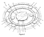
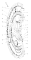
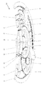
- FIG. figure 1 illustrate a particular embodiment of a gear train adapted for a display as illustrated in FIG. figure 1 .
- the concrete example which follows is given purely by way of example, and it is clear that variations are naturally possible, not only in which concerns the gear ratios and the speeds and directions of rotation, but also with respect to the arrangement of the components of the gear, for which a very large number of variants is possible.
- the directions of rotation are given as seen on the dial side, that is to say with respect to the views of the figures 2 and 3.
- the display device 100 illustrated in the figures comprises a pinion on the floor 1 driven in the clockwise direction in a conventional manner by a basic movement (not illustrated) that includes the timepiece in which the display device 100 is integrated.
- the pinion on pavement 1 is integral in rotation with, and concentric with, a wheel on pavement 11, which has a greater number of teeth than the pinion on pavement 1.
- the pinion on pavement 1 and the wheel on pavement 11 together form a
- the pavement wheel 11 meshes with a minute wheel 14 by means of a pair of double gears, each composed of a first return 12 and a second return 13 mutually integral in rotation with each other. pair, and which are supported by a fixed frame 10, attached to a frame member of the base movement (not shown) and serving as a support.
- the minute wheel 14 is rotatably connected to the minute hand 15, and the gear ratios between the road wheel 11, the first gear 12, the second gear 13 and the minute wheel 14 can be selected as desired.
- the first and second references 12, 13 have a different number of teeth, but it goes without saying that they can have the same number. In addition, it goes without saying that the number of double pinions 12, 13 can be chosen at will.
- the driving of the minute hand 14 is therefore effected by means of a simple gear train.
- the driving of the hour hand 16 as well as that of the minute disc 9 and the hour disc 7 is carried out against by means of a complex two-stage planetary gear, as will be described later.
- the mobile chassis 5 carries satellite mobiles, each composed of a set of a first planet gear 3 which meshes with the fixed crown 4, a satellite wheel 2 which meshes with the pinion on roadway 1, and a second satellite pinion 6 which meshes with an internal toothing that includes the hours disk 7, the components of this set being mutually integral in rotation each relative to the others.
- the hour disk 7 is constructed as an annular disc or crown, double toothed, and has an internal toothing and external teeth. In the illustrated embodiment, these teeth are formed throughout the thickness of the disk and are therefore visible to the user. In order to hide the teeth, it is possible to provide a plate which is superimposed on the crown and extends in overlapping of the teeth, and which carries indications of the time.
- the movable frame carries an index finger forming the hour hand 16, and, by rotating the pinion on the roadway 1, the hour hand 16 and the hours disk 7 each turn counterclockwise with a relative angular speed of a turn by twelve hours, one relative to the other. Therefore, the hour hand 15 can correctly indicate the time on the hour scale, while these two elements rotate at different absolute speeds.
- the second stage of the differential gear has as its first input the external toothing of the hour disc 7, as the second input the movable frame 5, and as the output the minute disc 9, which is also formed as a ring gear.
- the mobile frame 5 carries four additional planet gears 8, which mesh on one side with the external toothing of the hour disk 7, and on the other side an internal toothing that includes the minute disk 9.
- the following table specifies the number of teeth and the number of revolutions per hour of the components of the display device 100 described above and illustrated in the figures: Component Number of teeth Number of revolutions per hour Period (hours) Pinion on pavement 1 40 1 1 Satellite wheel 2 90 -3/8 8/3 Satellite gear 3 26 -3/8 8/3 Fixed crown 4 104 0 0 Mobile chassis 5 - -1/8 8 Satellite gear 6 26 -3/8 8/3 Hard hours 7 156 (interior) -5/24 24/5 184 (outside) Extra satellite gear 8 26 1885/4056 4056/1885 Record of minutes 9 236 -85/1416 1416-1485 Fixed frame 10 - 0 0 Wheel on roadway 11 121 1 1 First return 12 12 -121 / 12 12/121 Second reference 13 11 -121 / 12 12/121 Wheel of minutes 14 118 1331/1416 1416/1331 Needle minute 15 - 1331/1416 1416/1331 Needle of hours 16 - -1/8 8
- the hours display has a period of 24 hours, a period of time during which the hour hand 16 has traveled three times the dial counter-clockwise, and the hour disc 7 will have completed 5 full turns also in counter clockwise.
- the display of the minutes has a periodicity of 1416 hours, that is to say 59 days, which also represents the periodicity of the complete display.
- the minute and hour indicating members may be disks having one or more indexes.
- the hour hand 16 can be separated from the movable frame 5 and can be rotationally fixed or kinematically connected therewith, and / or can indicate on a 24 hour scale.
- the number of mobiles and / or satellite gears can be chosen differently.
- the minute hand can be driven by means of a planetary gear, and the planetary gear for driving the hour hand 16 and the discs 7, 9 can be replaced by one or more single gear trains, or a combination of planetary and single gears.
- the pavement mobile 1, 11 may alternatively be any other mobile, intended to rotate at any other angular velocity.
- the relationship between the diameters of the minute disc 9 and the hour disc 7 can be reversed, the minute disc 9 being of smaller diameter than the hour disc 7.
Landscapes
- Physics & Mathematics (AREA)
- General Physics & Mathematics (AREA)
- Geometry (AREA)
- Electromechanical Clocks (AREA)
Priority Applications (2)
| Application Number | Priority Date | Filing Date | Title |
|---|---|---|---|
| EP14182504.2A EP2990884A1 (de) | 2014-08-27 | 2014-08-27 | Anzeigevorrichtung für Uhr |
| CH01219/15A CH710064B1 (fr) | 2014-08-27 | 2015-08-25 | Dispositif d'affichage pour pièce d'horlogerie. |
Applications Claiming Priority (1)
| Application Number | Priority Date | Filing Date | Title |
|---|---|---|---|
| EP14182504.2A EP2990884A1 (de) | 2014-08-27 | 2014-08-27 | Anzeigevorrichtung für Uhr |
Publications (1)
| Publication Number | Publication Date |
|---|---|
| EP2990884A1 true EP2990884A1 (de) | 2016-03-02 |
Family
ID=51421869
Family Applications (1)
| Application Number | Title | Priority Date | Filing Date |
|---|---|---|---|
| EP14182504.2A Withdrawn EP2990884A1 (de) | 2014-08-27 | 2014-08-27 | Anzeigevorrichtung für Uhr |
Country Status (2)
| Country | Link |
|---|---|
| EP (1) | EP2990884A1 (de) |
| CH (1) | CH710064B1 (de) |
Cited By (1)
| Publication number | Priority date | Publication date | Assignee | Title |
|---|---|---|---|---|
| CN114815565A (zh) * | 2021-01-27 | 2022-07-29 | 李一龙 | 一种行星手表指示机构 |
Citations (3)
| Publication number | Priority date | Publication date | Assignee | Title |
|---|---|---|---|---|
| CH254299A (de) | 1945-06-23 | 1948-04-30 | Petersen T Miland | Uhr. |
| CH695224A5 (de) | 2004-10-22 | 2006-01-31 | Max Bleuler | Uhr mit drehbarem Minutenzifferblatt. |
| DE102011114466A1 (de) | 2011-09-28 | 2013-03-28 | Mho Ag | Uhr |
-
2014
- 2014-08-27 EP EP14182504.2A patent/EP2990884A1/de not_active Withdrawn
-
2015
- 2015-08-25 CH CH01219/15A patent/CH710064B1/fr unknown
Patent Citations (3)
| Publication number | Priority date | Publication date | Assignee | Title |
|---|---|---|---|---|
| CH254299A (de) | 1945-06-23 | 1948-04-30 | Petersen T Miland | Uhr. |
| CH695224A5 (de) | 2004-10-22 | 2006-01-31 | Max Bleuler | Uhr mit drehbarem Minutenzifferblatt. |
| DE102011114466A1 (de) | 2011-09-28 | 2013-03-28 | Mho Ag | Uhr |
Cited By (1)
| Publication number | Priority date | Publication date | Assignee | Title |
|---|---|---|---|---|
| CN114815565A (zh) * | 2021-01-27 | 2022-07-29 | 李一龙 | 一种行星手表指示机构 |
Also Published As
| Publication number | Publication date |
|---|---|
| CH710064A2 (fr) | 2016-02-29 |
| CH710064B1 (fr) | 2019-06-14 |
Similar Documents
| Publication | Publication Date | Title |
|---|---|---|
| EP2392976B1 (de) | Mondphasenanzeigemechanismus | |
| EP2009517B1 (de) | Uhr mit Mondphasenanzeige | |
| EP3029531B1 (de) | Anzeigevorrichtung von Perioden, die einen Jahreszyklus bilden | |
| EP2985660A1 (de) | Uhranzeigevorrichtung einer Uhrzeitanzeige oder eines abgeleiteten Uhrzeitwerts | |
| WO2004088435A2 (fr) | Mécanisme d'affichage du quantième pour mouvement de montre | |
| CH702422B1 (fr) | Pièce d'horlogerie. | |
| EP0258720B1 (de) | Uhrwerk zum Feststellen der Stellung der Gestirne | |
| EP3857313A2 (de) | Anzeigemechanismus mit einer einzigen öffnung | |
| WO2010108947A1 (fr) | Dispositif d'affichage | |
| EP2720090B1 (de) | Universaluhr | |
| EP3764171B1 (de) | Anzeigemechanismus eines uhranzeigewerts | |
| CH710064A2 (fr) | Dispositif d'affichage pour pièce d'horlogerie. | |
| CH706348B1 (fr) | Pièce d'horlogerie universelle. | |
| EP2993532B1 (de) | Antriebsmechanismus mindestens eines beweglichen elements | |
| CH716584A2 (fr) | Aiguille rotative autour de deux axes. | |
| EP2741150B1 (de) | Mehrfachkäfig-Tourbillon, Uhrwerk und Uhr, die ein solches Mehrfachkäfig-Tourbillon umfasst | |
| CH715546A2 (fr) | Mécanisme d'affichage pour mouvement horloger. | |
| CH688171B5 (fr) | Mécanisme additionnel de représentation astronomique pour pièces d'horlogerie. | |
| WO2006108878A1 (fr) | Mecanisme d'affichage sautant de l’heure pour piece d’horlogerie | |
| EP3333640A1 (de) | Mechanismus der wandernden zeitgleichung, der durch eine differenzialvorrichtung gesteuert wird | |
| EP2643735A1 (de) | Anzeigemechanismus für eine uhr | |
| CH709186A2 (fr) | Dispositif d'affichage de la date pour une pièce d'horlogerie. | |
| CH707556A2 (fr) | Mouvement horloger à fonction compte à rebours. | |
| WO2009115592A1 (fr) | Piece d'horlogerie | |
| EP2042945A2 (de) | Monatsanzeigevorrichtung für eine Uhr |
Legal Events
| Date | Code | Title | Description |
|---|---|---|---|
| PUAI | Public reference made under article 153(3) epc to a published international application that has entered the european phase |
Free format text: ORIGINAL CODE: 0009012 |
|
| AK | Designated contracting states |
Kind code of ref document: A1 Designated state(s): AL AT BE BG CH CY CZ DE DK EE ES FI FR GB GR HR HU IE IS IT LI LT LU LV MC MK MT NL NO PL PT RO RS SE SI SK SM TR |
|
| AX | Request for extension of the european patent |
Extension state: BA ME |
|
| STAA | Information on the status of an ep patent application or granted ep patent |
Free format text: STATUS: THE APPLICATION IS DEEMED TO BE WITHDRAWN |
|
| 18D | Application deemed to be withdrawn |
Effective date: 20160903 |