EP2990687A1 - Schaltzahnrad für hohe Getriebespreizung - Google Patents
Schaltzahnrad für hohe Getriebespreizung Download PDFInfo
- Publication number
- EP2990687A1 EP2990687A1 EP14183016.6A EP14183016A EP2990687A1 EP 2990687 A1 EP2990687 A1 EP 2990687A1 EP 14183016 A EP14183016 A EP 14183016A EP 2990687 A1 EP2990687 A1 EP 2990687A1
- Authority
- EP
- European Patent Office
- Prior art keywords
- gear
- output shaft
- gears
- ring member
- outer diameter
- Prior art date
- Legal status (The legal status is an assumption and is not a legal conclusion. Google has not performed a legal analysis and makes no representation as to the accuracy of the status listed.)
- Withdrawn
Links
Images


Classifications
-
- F—MECHANICAL ENGINEERING; LIGHTING; HEATING; WEAPONS; BLASTING
- F16—ENGINEERING ELEMENTS AND UNITS; GENERAL MEASURES FOR PRODUCING AND MAINTAINING EFFECTIVE FUNCTIONING OF MACHINES OR INSTALLATIONS; THERMAL INSULATION IN GENERAL
- F16H—GEARING
- F16H3/00—Toothed gearings for conveying rotary motion with variable gear ratio or for reversing rotary motion
- F16H3/02—Toothed gearings for conveying rotary motion with variable gear ratio or for reversing rotary motion without gears having orbital motion
- F16H3/08—Toothed gearings for conveying rotary motion with variable gear ratio or for reversing rotary motion without gears having orbital motion exclusively or essentially with continuously meshing gears, that can be disengaged from their shafts
- F16H3/083—Toothed gearings for conveying rotary motion with variable gear ratio or for reversing rotary motion without gears having orbital motion exclusively or essentially with continuously meshing gears, that can be disengaged from their shafts with radially acting and axially controlled clutching members, e.g. sliding keys
-
- F—MECHANICAL ENGINEERING; LIGHTING; HEATING; WEAPONS; BLASTING
- F16—ENGINEERING ELEMENTS AND UNITS; GENERAL MEASURES FOR PRODUCING AND MAINTAINING EFFECTIVE FUNCTIONING OF MACHINES OR INSTALLATIONS; THERMAL INSULATION IN GENERAL
- F16H—GEARING
- F16H15/00—Gearings for conveying rotary motion with variable gear ratio, or for reversing rotary motion, by friction between rotary members
- F16H15/48—Gearings for conveying rotary motion with variable gear ratio, or for reversing rotary motion, by friction between rotary members with members having orbital motion
- F16H15/50—Gearings providing a continuous range of gear ratios
- F16H15/52—Gearings providing a continuous range of gear ratios in which a member of uniform effective diameter mounted on a shaft may co-operate with different parts of another member
-
- F—MECHANICAL ENGINEERING; LIGHTING; HEATING; WEAPONS; BLASTING
- F16—ENGINEERING ELEMENTS AND UNITS; GENERAL MEASURES FOR PRODUCING AND MAINTAINING EFFECTIVE FUNCTIONING OF MACHINES OR INSTALLATIONS; THERMAL INSULATION IN GENERAL
- F16H—GEARING
- F16H55/00—Elements with teeth or friction surfaces for conveying motion; Worms, pulleys or sheaves for gearing mechanisms
- F16H55/02—Toothed members; Worms
- F16H55/17—Toothed wheels
-
- F—MECHANICAL ENGINEERING; LIGHTING; HEATING; WEAPONS; BLASTING
- F16—ENGINEERING ELEMENTS AND UNITS; GENERAL MEASURES FOR PRODUCING AND MAINTAINING EFFECTIVE FUNCTIONING OF MACHINES OR INSTALLATIONS; THERMAL INSULATION IN GENERAL
- F16H—GEARING
- F16H3/00—Toothed gearings for conveying rotary motion with variable gear ratio or for reversing rotary motion
- F16H3/02—Toothed gearings for conveying rotary motion with variable gear ratio or for reversing rotary motion without gears having orbital motion
- F16H3/08—Toothed gearings for conveying rotary motion with variable gear ratio or for reversing rotary motion without gears having orbital motion exclusively or essentially with continuously meshing gears, that can be disengaged from their shafts
- F16H2003/0807—Toothed gearings for conveying rotary motion with variable gear ratio or for reversing rotary motion without gears having orbital motion exclusively or essentially with continuously meshing gears, that can be disengaged from their shafts with gear ratios in which the power is transferred by axially coupling idle gears
Definitions
- the present invention relates to a gear for a transmission, in particular a pull key.
- a speed or torque from a first shaft (drive shaft) to a second shaft (output shaft) is transmitted.
- a plurality of different sized gears i. Gears with different sizes outside diameters.
- the two shafts are arranged in the transmission to each other so that the individual gears of the drive shaft engage in the gears of the output shaft.
- the individual gears of the two shafts are in different proportions to each other in engagement.
- different ratios of the two shafts in the transmission are possible.
- gears of the drive shaft are fixed (i.e., frictionally engaged) to the drive shaft.
- the output shaft is designed as a hollow shaft, in which a pull-type wedge (also called switch pin) is located.
- the draw key can be moved by means of a shift rod in the axial direction within the output shaft designed as a hollow shaft output shaft.
- the individual gears of the output shaft have on the inside a driving contour in the form of opposite grooves. In these grooves, the pulling wedge can be inserted, resulting in a positive or non-positive connection between the output shaft and the respective gear. Because of this positive or non-positive connection between the output shaft and the respective gear of the output shaft, the rotational speed or the torque of the drive shaft via the corresponding gears of the two shafts are transmitted to the output shaft.
- the largest possible gear spread is of great importance.
- the gear spread designates this Size ratio between the largest gear (largest outer diameter of the gear) to the smallest gear (smallest outer diameter of the gear). Due to the often limited space in the interior of the gear housing, however, the largest gear can not assume an unlimited outer diameter.
- the outer diameter of the smallest gear in turn, can not fall below a minimum value due to the necessary minimum diameter of the output shaft. This minimum value is often influenced by certain strength values and robustness requirements of this small gear, as even the smallest gear in the transmission must withstand and transmit relatively high speeds and a relatively high torque. In other words, the outer diameter of the smallest gear is always considerably larger than the outer diameter of the output shaft.
- Object of the present invention is therefore to provide a gear for a transmission, in particular a pull key, available, with the largest possible gear spread can be achieved.
- the gear includes a first ring element and a second ring element, wherein the first ring element has a driving contour for receiving a shaft pin of the transmission and the second ring element has a toothing on an outer surface.
- the dimensioning of the toothing of the gear from the dimensioning of the driving contour for receiving a shaft pin of the transmission is decoupled and variably framed.
- the outer diameter of the toothing can be made smaller than the outer diameter of the driving contour, whereby a smaller gear and consequently a large gear spread can be achieved.
- the second ring member is positioned in a direction behind the first ring member and the outer diameter of the second ring member is smaller than the outer diameter of the first ring member. This ensures that the outer diameter of the second Ring element together with the toothing can be smaller than the outer diameter of the first ring element together with the driving contour.
- the entrainment contour contains at least four grooves lying opposite the inner surface of the first annular element. In this way, a quick recording of the shaft pin in the grooves of the driving contour and thus a faster switching to another gear can be ensured.
- Fig. 1 showed an output shaft 1 with a first gear 2, second gear 3, third gear 4 and fourth gear 5.
- Each of the gears 2, 3, 4, 5 has on the respective outer surface 6, 7, 8, 9 a corresponding toothing 10, 11th , 12, 13 on.
- the four gears 2, 3, 4, 5 have different outer diameter.
- the first gear 2 has the largest outer diameter
- the second gear 3 has the second largest outer diameter
- the third gear 4 has the third largest outer diameter
- the fourth gear 5 has the fourth largest and thus smallest outer diameter.
- the output shaft 1 and the four gears 2, 3, 4, 5 are part of a (not shown) Wedge gear.
- the drive wedge gear further includes a drive shaft on which a first gear, second gear, third gear and fourth gear are also positioned.
- the four gears of the drive shaft also have different sized outer diameter.
- the drive shaft and the first gear, second gear, third gear and fourth gear on the drive shaft is not shown in the figures.
- the four gears 2, 3, 4, 5 of the output shaft 1 and the drive shaft are positioned in a reverse ratio to each other so that the gears of the gears mesh.
- the output shaft 1 and the drive shaft are positioned parallel to each other in the transmission.
- the teeth 10 of the gear 2 of the output shaft with the largest outer diameter engages in the toothing of the gear of the drive shaft with the smallest outer diameter.
- the remaining gears 3, 4, 5 of the output shaft 1 and drive shaft are positioned according to their outer diameters corresponding to each other. Due to the size different arrangement of the gears with moving outer diameters 1 different ratios of speed and torque can be generated between the drive shaft and the output shaft.
- each of the four gears 2, 3, 4, 5 at the respective outer surface 6, 7, 8, 9, a corresponding toothing 10, 11, 12, 13 and on the inner surface 14, 15, 16, 17 a number of opposite Grooves 20.
- the grooves 20 serve to receive a pull key 30.
- the output shaft 1 has a through hole 19.
- a shift rod 22 is positioned in the through hole 19.
- the shift rod 22 can be displaced in and against the axial direction N relative to the output shaft 1.
- the shift rod 22 has a first end 22a and a second end 22b. In the vicinity of the first end 22a of the shift rod 22 of the pull key 30 (also called switching pin) is attached.
- the pull key 30 includes a cylindrical body 32 having a first end 32a and a second end 32b.
- the main body 32 of the pull key 30 is arranged at right angles to the longitudinal extent of the output shaft 1 and the axial direction N. The first end 32 a and the second end 32 b of the main body 32 protrude from the output shaft 1.
- the pull key 30 is dimensioned such that the first end 32a and the second end 32b of the base body 32 can be inserted into the respective grooves 20 of the individual four gears 2, 3, 4, 5.
- the pull key 30 is inserted into the respective grooves 20 of one of the four gears 2, 3, 4, 5, there is a frictional connection between the output shaft 1, the pull key 30 and the respective gear 2, 3, 4, 5.
- the fourth gear 5 includes a first ring member 50 and a second ring member 60th
- the first ring member 50 includes a first end 50a, a second end 50b, an outer surface 52, and an inner surface 54 (see FIG. Fig. 10 ).
- the outer surface 52 of the first ring element 50 is designed as a continuous surface.
- the inner surface 54 of the first ring member 50 includes a driving contour 70.
- the driving contour 70 includes six grooves 41, 42, 43, 44, 45, 46, which are divided into three pairs of grooves, each with two opposing grooves.
- the six grooves 41, 42, 43, 44, 45, 46 are equally spaced from each other on the inner surface 54 of the first ring member 50 is positioned.
- the grooves 41, 42, 43, 44, 45, 46 extends around the driving contour 70, the inner surface 54, which is designed as a smooth continuous surface.
- the driving contour 70 may include fewer or more than six grooves or three pairs of grooves.
- the pairs of grooves serve to receive the first end 32 a and the second end 32 b of the main body 32 of the draw key 30.
- the entrainment contour 70 is positioned at a certain distance X from the first end 50 a of the first ring element 50. Of the Distance X of the driving contour 70 to the first end 50a of the first ring element 50 serves to more easily insert the pulling wedge 30 into the driving contour 70 during a gear change.
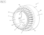
- the second ring member 60 includes first end 60a, a second end 60b, an outer surface 62, and an inner surface 64. As particularly shown in FIG Fig. 11 shown, on the outer surface 62 of the second ring member 60, the circumferential toothing 13 is positioned.
- the inner surface 64 of the second ring member 60 is designed as a smooth continuous surface.
- the first ring element 50 and the second ring element 60 are positioned one behind the other in the axial direction N, so that the second end 54 of the first ring element 50 bears against the first end 62 of the second ring element 60.
- the outer diameter A of the first ring member 50 is larger than the outer diameter B of the second ring member 60.
- the outer diameter B of the second ring element 60 together with the toothing 13 is only slightly larger than the outer diameter C of the output shaft 1 (see FIG. Fig. 2 ).
- the surface 90 around the entrainment contour 70 and the inner surface 64 of the second ring element 60 form a smooth continuous running surface, so that the surface 100 of the output shaft 1 is in large contact with the surface 90 around the entrainment contour 70 and the inner surface 64 of the second ring element 60.
- This large-area contact is a particularly quiet circulation, i. without jumping or seizing, the fourth gear 5 is ensured around the output shaft 1.
- the toothing and the driving contour of the gear according to the invention can be produced by cold extrusion. However, it is also possible that the gear according to the invention is also produced by any other suitable manufacturing method.
Priority Applications (7)
| Application Number | Priority Date | Filing Date | Title |
|---|---|---|---|
| EP14183016.6A EP2990687A1 (de) | 2014-09-01 | 2014-09-01 | Schaltzahnrad für hohe Getriebespreizung |
| CA2957470A CA2957470A1 (en) | 2014-09-01 | 2015-08-26 | Gear wheel for high gear-ratio spread |
| US15/507,625 US20170284509A1 (en) | 2014-09-01 | 2015-08-26 | Shift Gear Wheel for High Gear Ratio Spread |
| BR112017002545A BR112017002545A2 (pt) | 2014-09-01 | 2015-08-26 | engrenagem de mudança para alta gama de relações de transmissão |
| RU2017110882A RU2017110882A (ru) | 2014-09-01 | 2015-08-26 | Ведущая шестерня для большого диапазона передаточных чисел трансмиссии |
| EP15754223.4A EP3189252A1 (de) | 2014-09-01 | 2015-08-26 | Schaltzahnrad für hohe getriebespreizung |
| PCT/EP2015/069511 WO2016034468A1 (de) | 2014-09-01 | 2015-08-26 | Schaltzahnrad für hohe getriebespreizung |
Applications Claiming Priority (1)
| Application Number | Priority Date | Filing Date | Title |
|---|---|---|---|
| EP14183016.6A EP2990687A1 (de) | 2014-09-01 | 2014-09-01 | Schaltzahnrad für hohe Getriebespreizung |
Publications (1)
| Publication Number | Publication Date |
|---|---|
| EP2990687A1 true EP2990687A1 (de) | 2016-03-02 |
Family
ID=51429131
Family Applications (2)
| Application Number | Title | Priority Date | Filing Date |
|---|---|---|---|
| EP14183016.6A Withdrawn EP2990687A1 (de) | 2014-09-01 | 2014-09-01 | Schaltzahnrad für hohe Getriebespreizung |
| EP15754223.4A Withdrawn EP3189252A1 (de) | 2014-09-01 | 2015-08-26 | Schaltzahnrad für hohe getriebespreizung |
Family Applications After (1)
| Application Number | Title | Priority Date | Filing Date |
|---|---|---|---|
| EP15754223.4A Withdrawn EP3189252A1 (de) | 2014-09-01 | 2015-08-26 | Schaltzahnrad für hohe getriebespreizung |
Country Status (6)
| Country | Link |
|---|---|
| US (1) | US20170284509A1 (ru) |
| EP (2) | EP2990687A1 (ru) |
| BR (1) | BR112017002545A2 (ru) |
| CA (1) | CA2957470A1 (ru) |
| RU (1) | RU2017110882A (ru) |
| WO (1) | WO2016034468A1 (ru) |
Cited By (1)
| Publication number | Priority date | Publication date | Assignee | Title |
|---|---|---|---|---|
| CN106352028A (zh) * | 2016-05-28 | 2017-01-25 | 重庆万虎机电有限责任公司 | 一种微耕机、变速箱及其变速机构 |
Families Citing this family (2)
| Publication number | Priority date | Publication date | Assignee | Title |
|---|---|---|---|---|
| EP3527840A1 (en) * | 2018-02-20 | 2019-08-21 | Ningbo Geely Automobile Research & Development Co., Ltd. | A gear wheel |
| USD956841S1 (en) * | 2020-04-01 | 2022-07-05 | Robotis Co., Ltd. | Gear for actuator |
Citations (3)
| Publication number | Priority date | Publication date | Assignee | Title |
|---|---|---|---|---|
| GB347960A (en) * | 1930-06-27 | 1931-05-07 | Wise Patent And Dev Company | Improvements in friction clutch mechanism |
| DE1500488A1 (de) * | 1965-12-22 | 1969-07-10 | Rockwell Gmbh | Ziehkeilgetriebe,insbesondere fuer Motorfahrraeder |
| US20020091033A1 (en) * | 2001-01-09 | 2002-07-11 | Tianfu Li | Transmission mechanism |
-
2014
- 2014-09-01 EP EP14183016.6A patent/EP2990687A1/de not_active Withdrawn
-
2015
- 2015-08-26 RU RU2017110882A patent/RU2017110882A/ru not_active Application Discontinuation
- 2015-08-26 WO PCT/EP2015/069511 patent/WO2016034468A1/de active Application Filing
- 2015-08-26 US US15/507,625 patent/US20170284509A1/en not_active Abandoned
- 2015-08-26 EP EP15754223.4A patent/EP3189252A1/de not_active Withdrawn
- 2015-08-26 CA CA2957470A patent/CA2957470A1/en not_active Abandoned
- 2015-08-26 BR BR112017002545A patent/BR112017002545A2/pt not_active Application Discontinuation
Patent Citations (3)
| Publication number | Priority date | Publication date | Assignee | Title |
|---|---|---|---|---|
| GB347960A (en) * | 1930-06-27 | 1931-05-07 | Wise Patent And Dev Company | Improvements in friction clutch mechanism |
| DE1500488A1 (de) * | 1965-12-22 | 1969-07-10 | Rockwell Gmbh | Ziehkeilgetriebe,insbesondere fuer Motorfahrraeder |
| US20020091033A1 (en) * | 2001-01-09 | 2002-07-11 | Tianfu Li | Transmission mechanism |
Cited By (1)
| Publication number | Priority date | Publication date | Assignee | Title |
|---|---|---|---|---|
| CN106352028A (zh) * | 2016-05-28 | 2017-01-25 | 重庆万虎机电有限责任公司 | 一种微耕机、变速箱及其变速机构 |
Also Published As
| Publication number | Publication date |
|---|---|
| WO2016034468A1 (de) | 2016-03-10 |
| BR112017002545A2 (pt) | 2017-12-05 |
| EP3189252A1 (de) | 2017-07-12 |
| US20170284509A1 (en) | 2017-10-05 |
| RU2017110882A (ru) | 2018-10-03 |
| CA2957470A1 (en) | 2016-03-10 |
Similar Documents
| Publication | Publication Date | Title |
|---|---|---|
| DE1450722B2 (de) | Sperrsynchronisierkupplung | |
| CH636518A5 (de) | Zahnaerztliches handstueck. | |
| DE202011108822U1 (de) | Ein Nabenaufbau mit einem in beiden Richtungen beweglichen Klinkenschaltwerk | |
| DE3505323C2 (ru) | ||
| WO2016034468A1 (de) | Schaltzahnrad für hohe getriebespreizung | |
| DE2803933A1 (de) | Untersetzungsgetriebe fuer zahnaerztliche handstuecke | |
| DE19609666B4 (de) | Differentialgetriebe | |
| EP2655925B1 (de) | Verfahren zur modifizierung eines schaltgetriebes | |
| DE102009027719B4 (de) | Schaltkupplung | |
| DE102008049978A1 (de) | Schalteinheit mit Kupplungskörper | |
| DE102018108698B4 (de) | Differenzialbaugruppe und mehrteilige Kreuzstiftbaugruppe | |
| DE102012208126A1 (de) | Getriebeanordnung | |
| DE102015223506A1 (de) | Zweigängiges Getriebe | |
| DE19928597B4 (de) | Synchronisationseinrichtung für Schaltgetriebe | |
| DE3500992A1 (de) | Mehrganggetriebe fuer ein fahrzeug | |
| DE102021203418A1 (de) | Getriebe für ein Fahrzeug | |
| DE202004006953U1 (de) | Schalteinrichtung für ein Wechselgetriebe mit vereinfachter Schaltkulisse | |
| DE2725039A1 (de) | Sperrsynchronisierung fuer wechselgetriebe von kraftfahrzeugen, insbesondere von nutzfahrzeugen | |
| DE102021203416A1 (de) | Getriebe für ein Fahrzeug | |
| DE10333268B4 (de) | Vorrichtung zur Umwandlung einer Drehbewegung in eine translatorische Bewegung | |
| DE3803845A1 (de) | Klauenschaltkupplung in einem stufenwechselgetriebe | |
| DE102004007815B4 (de) | Schaltgetriebe mit Sperrsynchronisation | |
| DE102005002480B4 (de) | Synchronisierungseinrichtung für ein Schaltgetriebe eines Kraftfahrzeuges | |
| DE19581879B4 (de) | Planetengetriebe | |
| DE607110C (de) | Vorrichtung zum Verhindern des Einrueckens von Klauenkupplungen in Zahnraederwechselgetrieben von Erreichung des Gleischlaufs der zu kuppelnden Glieder |
Legal Events
| Date | Code | Title | Description |
|---|---|---|---|
| PUAI | Public reference made under article 153(3) epc to a published international application that has entered the european phase |
Free format text: ORIGINAL CODE: 0009012 |
|
| AK | Designated contracting states |
Kind code of ref document: A1 Designated state(s): AL AT BE BG CH CY CZ DE DK EE ES FI FR GB GR HR HU IE IS IT LI LT LU LV MC MK MT NL NO PL PT RO RS SE SI SK SM TR |
|
| AX | Request for extension of the european patent |
Extension state: BA ME |
|
| STAA | Information on the status of an ep patent application or granted ep patent |
Free format text: STATUS: THE APPLICATION IS DEEMED TO BE WITHDRAWN |
|
| 18D | Application deemed to be withdrawn |
Effective date: 20160903 |