EP2989499B1 - Verfahren zur erfassung fokussierter bilder von objektträgern und abbildungsvorrichtung - Google Patents
Verfahren zur erfassung fokussierter bilder von objektträgern und abbildungsvorrichtung Download PDFInfo
- Publication number
- EP2989499B1 EP2989499B1 EP14738847.4A EP14738847A EP2989499B1 EP 2989499 B1 EP2989499 B1 EP 2989499B1 EP 14738847 A EP14738847 A EP 14738847A EP 2989499 B1 EP2989499 B1 EP 2989499B1
- Authority
- EP
- European Patent Office
- Prior art keywords
- slide
- offset
- focus
- section
- component
- Prior art date
- Legal status (The legal status is an assumption and is not a legal conclusion. Google has not performed a legal analysis and makes no representation as to the accuracy of the status listed.)
- Active
Links
Images


Classifications
-
- G—PHYSICS
- G02—OPTICS
- G02B—OPTICAL ELEMENTS, SYSTEMS OR APPARATUS
- G02B21/00—Microscopes
- G02B21/24—Base structure
- G02B21/241—Devices for focusing
- G02B21/244—Devices for focusing using image analysis techniques
-
- G—PHYSICS
- G02—OPTICS
- G02B—OPTICAL ELEMENTS, SYSTEMS OR APPARATUS
- G02B21/00—Microscopes
- G02B21/0004—Microscopes specially adapted for specific applications
- G02B21/002—Scanning microscopes
- G02B21/0024—Confocal scanning microscopes (CSOMs) or confocal "macroscopes"; Accessories which are not restricted to use with CSOMs, e.g. sample holders
- G02B21/0052—Optical details of the image generation
- G02B21/006—Optical details of the image generation focusing arrangements; selection of the plane to be imaged
-
- G—PHYSICS
- G02—OPTICS
- G02B—OPTICAL ELEMENTS, SYSTEMS OR APPARATUS
- G02B21/00—Microscopes
- G02B21/0004—Microscopes specially adapted for specific applications
- G02B21/002—Scanning microscopes
- G02B21/0024—Confocal scanning microscopes (CSOMs) or confocal "macroscopes"; Accessories which are not restricted to use with CSOMs, e.g. sample holders
- G02B21/0052—Optical details of the image generation
- G02B21/0072—Optical details of the image generation details concerning resolution or correction, including general design of CSOM objectives
-
- G—PHYSICS
- G02—OPTICS
- G02B—OPTICAL ELEMENTS, SYSTEMS OR APPARATUS
- G02B21/00—Microscopes
- G02B21/0004—Microscopes specially adapted for specific applications
- G02B21/002—Scanning microscopes
- G02B21/0024—Confocal scanning microscopes (CSOMs) or confocal "macroscopes"; Accessories which are not restricted to use with CSOMs, e.g. sample holders
- G02B21/008—Details of detection or image processing, including general computer control
-
- G—PHYSICS
- G02—OPTICS
- G02B—OPTICAL ELEMENTS, SYSTEMS OR APPARATUS
- G02B21/00—Microscopes
- G02B21/36—Microscopes arranged for photographic purposes or projection purposes or digital imaging or video purposes including associated control and data processing arrangements
- G02B21/365—Control or image processing arrangements for digital or video microscopes
- G02B21/367—Control or image processing arrangements for digital or video microscopes providing an output produced by processing a plurality of individual source images, e.g. image tiling, montage, composite images, depth sectioning, image comparison
-
- G—PHYSICS
- G06—COMPUTING OR CALCULATING; COUNTING
- G06T—IMAGE DATA PROCESSING OR GENERATION, IN GENERAL
- G06T7/00—Image analysis
- G06T7/80—Analysis of captured images to determine intrinsic or extrinsic camera parameters, i.e. camera calibration
-
- G—PHYSICS
- G06—COMPUTING OR CALCULATING; COUNTING
- G06V—IMAGE OR VIDEO RECOGNITION OR UNDERSTANDING
- G06V20/00—Scenes; Scene-specific elements
- G06V20/60—Type of objects
- G06V20/69—Microscopic objects, e.g. biological cells or cellular parts
-
- H—ELECTRICITY
- H04—ELECTRIC COMMUNICATION TECHNIQUE
- H04N—PICTORIAL COMMUNICATION, e.g. TELEVISION
- H04N23/00—Cameras or camera modules comprising electronic image sensors; Control thereof
- H04N23/10—Cameras or camera modules comprising electronic image sensors; Control thereof for generating image signals from different wavelengths
-
- H—ELECTRICITY
- H04—ELECTRIC COMMUNICATION TECHNIQUE
- H04N—PICTORIAL COMMUNICATION, e.g. TELEVISION
- H04N23/00—Cameras or camera modules comprising electronic image sensors; Control thereof
- H04N23/60—Control of cameras or camera modules
- H04N23/67—Focus control based on electronic image sensor signals
-
- G—PHYSICS
- G02—OPTICS
- G02B—OPTICAL ELEMENTS, SYSTEMS OR APPARATUS
- G02B21/00—Microscopes
- G02B21/16—Microscopes adapted for ultraviolet illumination ; Fluorescence microscopes
-
- G—PHYSICS
- G06—COMPUTING OR CALCULATING; COUNTING
- G06T—IMAGE DATA PROCESSING OR GENERATION, IN GENERAL
- G06T2207/00—Indexing scheme for image analysis or image enhancement
- G06T2207/10—Image acquisition modality
- G06T2207/10056—Microscopic image
Definitions
- the technology disclosed herein relates to computer-based systems for imaging microscope slides and auto-focus techniques.
- Digital pathology equipment is often used to produce digital images of microscope slides. Pathologists and histotechnologists often visually examine the digital images to obtain information about tissue samples and to identify the most appropriate treatment to improve a clinical outcome.
- automated slide scanners often acquire images in each of red, green, and blue color (RGB) channels and combine the images to produce a RGB image. Scanners also acquire a plurality of image channels with different spectral characteristics, like e.g. fluorescence imagers with a bench of multiple or tunable filters to acquire image data.
- automated slide scanning often includes automatically scanning a tissue sample at a large number of different Z-planes. Many of the captured images provide little or no value because the image data is often out of focus in most of the Z-planes. This problem also affects fluorescence imaging using a filter bench.
- the Z-plane for the best focus in the blue or green color channel may not be the Z-plane for the best focus in the red color channel, especially if the features being imaged are small (for example, less than 20 times the wavelength of light).
- Image blur in one color channel can impair the overall color image quality leading to serious problems with interpretation, diagnosis, and/or automated image analysis.
- color slide scanners can acquire a complete Z-stack of images (e.g., a set of Z-stack of images for each color channel) and use complex auto-focus algorithms to create a single image from the Z-stacks.
- conventional color slide scanners can select a focus (or focal) plane for one channel and then scan other channels at the selected focus plane. For example, a focus plane can be selected for the best focus of the green channel. The slide scanner acquires images in the red and blue channels at that focus plane to produce a color or multi-spectral image.
- the common focus plane used for all of the channels may not be the best focus plane for each channel, resulting in unwanted image blur in the composite image for features that are dominated by colors other than the one that dominated the focusing procedure.
- German patent application DE 10 2005 0940 827 A1 relates to a method for automatically compensating the longitudinal chromatic aberration of the imaging optics of a microscope which can be used in particular in fluorescence microscopy for the correction of the remaining longitudinal chromatic aberration of the imaging optics.
- United States patent application publication US 2012/0194729 A1 relates to methods and systems for automatically focusing multiple images of one or more objects on a substrate.
- the methods include obtaining, by a processor, a representative focal distance for a first location on the substrate based on a set of focal distances at known locations on the substrate.
- the methods also include acquiring, by an image acquisition device, a set of at least two images of the first location. The images are each acquired using a different focal distance at an offset from the representative focal distance.
- the methods further include estimating, by a processor, an ideal focal distance corresponding to the first location based on comparing a quality of focus for each of the images, and storing the estimated ideal focal distance and the first location in the set of focal distances at known locations.
- United States patent publication US 6,172,349 B1 relates to a method and apparatus for automatically focusing a high resolution microscope, wherein during setup the operator designates areas within each field of view where a measurement will be taken, and for each area of interest translates the microscope along its optical axis (Z-axis) while measuring the image intensities at discrete subareas within the area of interest. These image intensities are then evaluated, and those having the greatest signal-to-noise ratio and occurring at a common point along the Z-axis will be selected, and the corresponding subareas identified. During subsequent inspections of the area of interest, only light reflected from the identified subareas will be used to focus the microscope.
- the invention provides for a method for acquiring focused images of a microscope slide and an imaging apparatus in the independent claims. Embodiments are given in the dependent claims.
- At least some embodiments of the disclosed technology are imaging systems that enhance the focus of composite images by capturing images at focal planes selected to improve the balance between optical sharpness, color separability and human readability.
- Each channel e.g., a color channel
- filter band of a digital imager device can have a different focal plane.
- the "in focus" focal planes are selected to capture a limited number of images (e.g., one image per channel or filter band) to produce a composite image that is most optimally focused for all color channels while limiting imaging times, data storage, or the like.
- the imaging system thus produces, for example, highly-focused color images of a specimen by combining individual images in different color channels obtained at respective focal planes.
- the focal plane can correspond to captured images in a channel (or filter band) with the least amount of blur, sharpest image, etc.
- the imaging systems can image one or more calibration microscope slides (e.g., phantom slides, tissue-specific training slides, etc.) indicative of, for example, tissue characteristics of tissue samples from patients.
- the imaging system can analyze the acquired images of the calibration slides to evaluate, for example, distortion, color aberration, or other unwanted problems. In some calibration processes, the impact of color aberration or distortion between a single auto-focus plane for all color channels and the best individual focal plane for each color channel is determined.
- the imaging system can use model fitting techniques to process subsequent fields of views of the same tissue sample or different tissue samples.
- the model fit can be an offset or fitting technique involving, for example, polynomial fitting or other suitable fitting of a position of a specimen and a channel or band focal plan as variables.
- a Z-stack of images of one or more calibration slides can be obtained.
- the imaging system can determine the focal plane for each channel or filter band and compare that focal plane to a predicted focal plane from an auto-focus algorithm. This information is provided to the focus method applied when imaging an object like tissue, cells, etc. The information and, therefore, the auto-focus algorithm can be continuously or periodically updated based on the comparison to increase the accuracy of the auto-focus algorithm.
- the auto-focus algorithm is updated based on a comparison of images at a predicted focal plane and an actual in-focus focal plane.
- the comparison of images in one channel can be used to select focal planes in other channels.
- two images in a single channel can be used to determine optimal focal planes in additional channels.
- auto-focus algorithms of one channel can be adjusted based on an adjustment (e.g., focusing) of another channel. This can reduce overall processing time and enhance image quality.
- At least some embodiments of the disclosed technology are imaging systems that include a facility configured to improve the "sharpness" of captured images by capturing images at different focal planes for different color channels or filter bands.
- the facility For each color channel or filter band, the facility identifies the focal plane having the least amount of blur (i.e., the focal plane that is "most in focus") and uses these focal planes, for example, to capture focused images.
- the focused images can be combined to produce a focused composite image. For example, a focused red channel image, a focused green channel image, and a focused blue channel image can be combined to produce a focused color image. Because the facility uses an optimal focal plane for each color channel (or filter band), the amount of chromatic aberration observed in the final composite image can be reduced.
- the techniques described herein can be used to enhance known auto-focus and Z-slicing techniques, such as passive or active auto-focus techniques including, but not limited to, phase detection auto-focus techniques, contrast detection auto-focus techniques, and so on. Additional auto-focus, Z-slicing, and slide imaging techniques are described by Bradley and Bamform in " A One-pass Extended Depth of Field Algorithm Based on the Over-complete Discrete Wavelet Transform”; Image and Vision Computing '04 New Zealand (IVCNZ'04), Akaroa, New Zealand, pp. 279-284 (November 2004 ); U.S. Non-Provisional Patent App. No. 13/697,681, filed May 4, 2011 , entitled “Autofocus Imaging”; U.S. Provisional App. No.
- the facility generates an auto-focus model during a calibration phase or step and uses the generated auto-focus model during subsequent scans of slides and/or field of view scans to reduce scan time and data size while providing improved focus for each individual color channel (or filter band).
- the facility determines a "base" auto-focus plane for one image and then determines auto-focus plane “offsets" for various color channels (or filter bands).
- the calibration step includes analyzing one or more "phantom” or "training slides” that are representative of specimens (e.g., bacteria, biological material, and so on), tissue (e.g., breast tissue, tumor tissue, and so on), or other specimens to be scanned.
- a “base” value is determined by applying an auto-focus technique to the training slide(s) by analyzing images of the slide(s) captured at different focal planes.
- an auto-focus technique is employed, including those mentioned above and other auto-focus techniques.
- the "base” value in some embodiments, is generated using gray scale version of the slide(s).
- the calibration step further includes determining an "offset" value in Z for each color channel (or filter band) corresponding to the focal plane offering the highest degree of sharpness for the color channel (or filter band).
- the facility can determine each "offset” value by applying an auto-focus technique to a first slide by analyzing color channel or filter band-specific images of the slide(s) captured at different focal planes to identify the sharpest focal plane
- Each "offset" value is calculated as a difference from the "base value.” For example, if the "base” value is at a Z of 23 ⁇ m (micrometers) and the sharpest focal plane for a red color channel is at a Z of 24 ⁇ m, then the red color channel offset is +1 ⁇ m. As another example, if the "base” value is 25 ⁇ m and the sharpest focal plane for a red color channel is 24 ⁇ m, then the red color channel offset is -1 ⁇ m.
- the base value may correspond to measure of the lens relative to its overall range of movement. For example, if the lens has an overall range of movement of 50 ⁇ m, the base value may represent a measure between 0 ⁇ m and 50 ⁇ m along the overall range of movement.
- the resulting base and offset values can be combined into a single composite model by, for example, computing the average base and offset values for each slide position/color channel (or filter band), using the most common base and offset values, or other suitable aggregation techniques.
- the facility divides slide data into a grid (e.g., 1x1, 3x3, 9x9, 12x24, 100x1000, etc.) and performs the calibration step for each section of the grid. For example, if the facility divides slide data into a 3x3 grid, the facility generates one "base" value for each of the 9 sections and generates one offset value for each color channel or filter band for each of the 9 sections. In this manner, the model can be optimized for each section of the grid.
- the "base” values are calculated using a gray scale version of the captured image data, or luminosity values for the captured image data.
- At least one of the color channels can be acquired at the "base" auto-focus plane determined for the slide without an offset. Therefore, at least one color channel is imaged at the standard focus plane and with the focus plane modified by applying an offset as discussed above.
- a focus sharpness metric can be computed for the two focal planes acquired and the optimal plane (i.e., sharpest) can be selected for output.
- Appropriate focus sharpness optimization metrics can be based on some computation derived from or related to the gradient of image intensity in the x-direction and y-direction of an image. In one embodiment, the computation of such a metric can be performed by translating the image a few pixels in x-direction and/or y-direction and summing the absolute differences.
- Focus sharpness traditional “sharpness” metrics can be found in S. Pertuz, D. Puig, M. Angel Garcia, "Analysis of focus measure operators for shape-from-focus,” Pattern Recognition, Volume 46, Issue 5, May 2013, Pages 1415-1432 , where they are referred to as "focus measure operators”.
- Another method for computing a generalized focus sharpness metric is to carry out a median filter operation or other type of image smoothing on a monochrome image representing one color channel of the image or a combination of the color channels available in the image.
- the smoothed image can be subtracted or otherwise combined with the original to yield a scalar, vector or matrix that with higher absolute values when the image is in focus and lower absolute values when it is out of focus.
- Summing the absolute difference of the two images is one example of such a combining method.
- the median filter can be carried out in parallel multiple times, increasing the local application of the filter from 3x3 pixels to 5x5 pixels to 7x7 pixels, etc.
- the values corresponding to the maxima (or any other measure of intensity) in the resulting images, sometimes including the original, can be fit to a straight line or combined in some other way that characterizes the sequence of values.
- the slope of such a line is greater than the slope for an image that is not in sharp focus.
- FIG. 1 illustrates a computer-based system and environment for analyzing tissue specimens in accordance with an embodiment of the disclosed technology.
- An analyzing system 100 includes an imaging apparatus 110 and client computer systems 120. Specimen-bearing microscope slides can be loaded into the imaging apparatus 110.
- the imaging apparatus 110 can perform auto-focus techniques and produce images of the specimens in multiple color channels.
- the imaging apparatus includes a microscope for bright field and/or fluorescent imaging of the specimen-bearing microscope slides.
- the imaging apparatus 110 may further be a whole-slide scanner.
- One example whole-slide scanner is the VENTANA iScan HT product of the assignee Ventana Medical Systems, Inc. (Tucson, AZ).
- the images can be sent to the client computer systems 120 either through a direct connection (not shown) or via a network 130.
- the client computer systems 120 display images to users, such as pathologists, histotechnologists, or the like.
- the imaging apparatus 110 can include, without limitation, one or more image capture devices 111 and facilities 200. Internal components of the imaging apparatus 110 are shown in phantom line.
- Image capture devices 111 can include, without limitation, a digital imager 113 (e.g., a digital camera) with an optical system (e.g., one or more lenses 115, sensor focus lens groups, microscope objectives, etc.), imaging sensors (e.g., a charge-coupled device (CCD), a complimentary metal-oxide semiconductor (CMOS) image sensor, or the like), or the like.
- the digital imager 113 can include a plurality of lenses that cooperate to provide focusing (e.g., auto-focusing).
- a CCD sensor can capture a digital image of specimen slide 117.
- the digital imager 113 has red, green and blue color channels for producing color images and is operable to capture images at different focal planes
- the digital imager 113 is a monochromatic or color sensor
- the optical system includes multiple and/or tunable filters
- multispectral or color image channels are created by acquiring multiple images from imager 113 with different filters and/or filter settings.
- One method of producing a color image includes determining one or more scan areas comprising a region or slide position of the microscope slide that includes at least a portion of the specimen. The scan area may be divided into a plurality of snapshots. An image can be produced by combining the snapshots. The combined image of the whole specimen or slide can have snapshots with images in the RGB channels at the same or different focal planes.
- the imaging apparatus 110 can also include an access door 121 and a controller 123. Slide can be loaded into the imaging apparatus 110 via the access door 121, and the controller 123 can be used to control operation of the imaging apparatus 110.
- the imaging apparatus 110 and client computer systems 120 can include a desktop computer, a laptop computer, a tablet, or the like and can include digital electronic circuitry, firmware, hardware, memory, a computer storage medium, a computer program, a processor (including a programmed processor), or the like and can store digital images in binary form.
- the images can also be divided into a matrix of pixels.
- the pixels can include of a digital value of one or more bits, defined by the bit depth.
- the digital value may represent, for example, energy, brightness, color, intensity, density, elevation, or a classified value derived through image processing.
- Non-limiting exemplary digital image formats include, but are not limited to, bit-mapped, joint pictures expert group (JPEG), tagged image file format (TIFF), and graphics interchange format (GIF), as well as other digital data formats.
- the network 130 or a direct connection interconnects the imaging apparatus 110 and the client computer systems 120.
- the network 130 may include, without limitation, one or more gateways, routers, bridges, combinations thereof, or the like.
- the network 130 may include one or more servers and one or more websites that are accessible to users and can be used to send and receive information that the client computer systems 120 can utilize.
- a server may include, without limitation, one or more associated databases for storing information (e.g., digital images, algorithms, staining protocols, or the like).
- the network 130 can include, but is not limited to, data networks using the Transmission Control Protocol (TCP), User Datagram Protocol (UDP), Internet Protocol (IP) and other data protocols.
- TCP Transmission Control Protocol
- UDP User Datagram Protocol
- IP Internet Protocol
- the client computer systems 120 can perform the methods and techniques discussed herein. Components and features of the client computer system 120 can be mixed and matched with other components and features of the disclosed technology.
- FIG. 2 is a block diagram illustrating a facility 200 for enhancing auto-focus routines in some embodiments.
- the facility 200 comprises calibrate component 210, Z-calibrate component 220, scan components 230, 240, test component 250, slide data store 260, and model store 270.
- the facility can selectively invoke the calibrate component 210, Z-calibrate component 220, scan components 230, 240, and/or test component 250.
- the calibrate component 210 calibrates and generates a focal plane-based auto-focus model that can be applied to subsequently scanned slides.
- the Z-calibrate component 220 calibrates and generates a Z-slice-based auto-focus model that can be applied to subsequently scanned slides.
- the scan component 230 scans and generates images using a focal plane-based auto-focus model generated by the calibrate component 210.
- the Z-scan component 240 can scan and generate images using a Z-slice-based auto-focus model generated by the Z-calibrate component 210.
- the test component 250 determines whether a previously-generated model needs to be updated and, if so, updates the model.
- Slide data store 260 stores captured slide data (e.g., images, such as Z-slices, metadata, and so on).
- Model store 270 stores model information, such as base values and offset values for different slide positions and different slide data types.
- the model store 270 may include different models for different types of tissue or other imaged data.
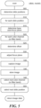
- FIG 3 is a flow diagram illustrating the processing of the calibrate component 210 of Figure 2 in accordance with some embodiments.
- the calibrate component 210 may be invoked for a single training slide or a series of training slides to generate an auto-focus model.
- the component determines a slide position or positions for the slide.
- the component is configured to generate values for a particular grid configuration, so the component identifies the area or areas of the slide corresponding to sections of the grid.
- the component may prompt a user to identify the slide positions.
- the component loops through each of the determined slide positions to generate base and offset values for each slide position.
- the component invokes an auto-focus technique to identify an in-focus focal "base" plane for the current slide and stores an indication of the focal plane (e.g., a distance from the lens or other portion of the imaging apparatus to the focal plane) and slide position.
- the base plane is determined by analyzing gray scale images of the slide.
- the component loops through each color channel (or filter band) to determine an offset value for each color channel (or filter band).
- the component invokes an auto-focus technique to identify an in-focus focal plane for the currently selected color channel (or filter band) and slide position.
- the in-focus plane can be determined based on a distance from the lens or other portion of the imaging apparatus to the focal plane.
- an offset for the currently selected color channel (or filter band) is determined based on the distance between the focal planes identified in blocks 325 and 315.
- the component stores the determined offset.
- the next color channel (or filter band), if any, is selected and the component then loops back to process the next color channel (or filter band).
- the component selects the next slide position, if any, and then loops back to process the next slide position.
- an auto-focus model is generated using the base and offset values determined for each slide position.
- the auto-focus model stores, for example, an indication of the number and location of slide positions, an indication of the type of material scanned (e.g., breast tissue, bacteria, etc.), a base value for each slide position corresponding to the base focal plane and, for each color channel or filter band, one offset value for each slide position.
- Table 1 provides an example of the type of data that may be stored in a model generated for tissue using a 3x3 grid layout.
- the model includes nine red channel offsets (offset red ), nine green channel offsets (offset green ), and nine blue channel offsets (offset blue ), one of each for each slide position.
- the model may also store an indication of the type of images that were used to determine the base focal plane (i.e. grayscale image).
- grayscale image an indication of the type of images that were used to determine the base focal plane.
- Figure 4 is a flowchart illustrating the processing of a Z-calibrate component 220 to calibrate and generate a Z-slice-based auto-focus model, in accordance with related examples not part of the present invention
- the component 220 may be invoked by the facility 200 for a single training slide or a series of training slides to generate an auto-focus model.
- the component generates Z-slices for the slide using any focus stacking technique.
- the component may retrieve stored Z-slices generated from previously captured slide data. In this manner, the disclosed techniques can be used to enhance the auto-focus of previously-captured slides.
- a slide position or positions for the slide can be determined.
- the component if the component is configured to generate values for a particular grid configuration, the component identifies the areas of the slide corresponding to sections of the grid. In some case, a user is prompted to identify the slide positions.
- the component loops through each of the determined slide positions to generate base and offset values for each slide position.
- Z-slices are analyzed to identify the Z-slice having the sharpest image by, for example, using known focus stacking techniques.
- the base Z-slice may be determined by analyzing gray scale version of each Z-slice. Or, the base Z-slice may be determined by analyzing a particular color channel or filter band.
- the component loops through each color channel (or filter band) to determine an offset value for each color channel (or filter band).
- the Z-slice having the sharpest image for the current color channel is identified.
- an offset for the currently selected color channel (or filter band) is determined based on the difference between the Z-slices identified in blocks 420 and 430.
- the component stores the determined offset.
- the next color channel (or filter band), if any, is selected and the component then loops back to process the next color channel (or filter band).
- the component selects the next slide position, if any, and then loops back to process the next slide position.
- an auto-focus model is generated using the base and offset values determined for each slide position.
- the auto-focus model stores, for example, an indication of the number and location of slide positions, an indication of the type of material scanned (e.g., breast tissue, bacteria), a base value for each slide position corresponding to the base Z-slice and, for each color channel or filter band, one offset value for each slide position.
- Table 2 provides an example of the type of data that may be stored in a model generated for tissue using a 3x3 grid layout.
- each Z-slices is identified by an index from 0 to 15.
- the model includes nine red channel offsets (offset red ), nine green channel offsets (offset green ), and nine blue channel offsets (offset blue ), one of each for each slide position.
- the model may also store an indication of the type of images that were used to determine the base focal plane). (i.e. grayscale image).
- Table 2 Although the data stored in Table 2 is shown in a format that is readily interpreted by a human, one skilled in the art will recognize that the data may be stored in any manner or data structure.
- Figure 5 is a flow diagram illustrating the processing of the scan component 230 of Figure 2 for capturing images of a slide based on the auto-focus model, in accordance with some embodiments.
- the component determines slide positions based on the model. Using the model of Table 1 as an example, the component may identify the portions of the slide corresponding to each position in the 3x3 grid by splitting the slide into 9 portions corresponding to the 3x3 grid. In some embodiments, the model may include additional information about the location of each portion if, for example, the portions are not the same size, which the scan component may use to determine the slide positions.
- the component loops through each of the determined slide positions to capture one or more images for each slide position.
- auto-focus technique is used to identify an in-focus focal "base" plane for the current slide.
- the base plane is identified by analyzing images generated in the same manner that the images used to identify the base planes in the model were generated. For example, if the base planes in the model were identified by analyzing gray scale images, then the scan component analyzes gray scale images of the current slide to determine the base plane for the current slide.
- the component loops through each of the color channels (or filter bands) to capture a corresponding image for each.
- the offset for the current color channel (or filter band) stored by the model is determined.
- the component adjusts the focal plane based on the "base" plane determined in block 515 and the offset.
- the component will adjust the focal plane to 2.1 ⁇ m.
- the component captures an image of the slide using the adjusted focal plane and the current color channel (or filter band).
- the captured image is stored.
- the next color channel (or filter band), if any, is selected and the component then loops back to process the next color channel (or filter band).
- the component selects the next slide position, if any, and then loops back to process the next slide position. The component then returns the captured image data for further processing and analysis.
- Figure 6 illustrates processing of the Z-scan component 240, which does not form part of the invention, for generating images for a slide based on a previously generated auto-focus model, such as the auto-focus model generated by the Z-calibrate.
- the component generates Z-slices for the current slide.
- slide positions are determined based on the model.
- the component may identify the portions of the slide corresponding to each position in the 3x3 grid by splitting the slide into 9 portions corresponding to the 3x3 grid.
- the model may include additional information about the location of each portion if, for example, the portions are not the same size, which the Z-scan component may use to determine the slide positions.
- the component loops through each of the determined slide positions to capture one or more images for each slide position.
- the generated Z-slices are analyzed to identify the Z-slice having the sharpest image.
- the base Z-slice is identified by analyzing images generated in the same manner that the images used to identify the base Z-slices in the model were generated. So, because the base Z-slices in the model were identified by analyzing gray scale images, then the Z-scan component analyzes gray scale images of the current slide to determine the base Z-slice for the current slide.
- the component loops through each of the color channels (or filter bands) to capture a corresponding image for each.
- the component determines the offset for the current color channel (or filter band) stored by the model.
- the component determines the offset Z-slice based on the base Z-slice determined in block 620 and the determined offset. For example, if the determined "base" Z-slice has an index of 7 and the offset is -2, then the component will identify the Z-slice corresponding to an index of 5.
- the component determines a sharpness of the base Z-slice using a focus sharpness measure, such as the sum of absolute differences between an image and the same image shifted (e.g., shifted a few pixels in one direction), the sum of absolute differences between an image and the result of filtering the imaging with a smoothing operation, a focus sharpness measure extracted after filtering the image with a multitude of smoothing operations at different filter scales, or any combination thereof.
- a focus sharpness measure such as the sum of absolute differences between an image and the same image shifted (e.g., shifted a few pixels in one direction), the sum of absolute differences between an image and the result of filtering the imaging with a smoothing operation, a focus sharpness measure extracted after filtering the image with a multitude of smoothing operations at different filter scales, or any combination thereof.
- the component determines a sharpness of the offset Z-slice.
- decision block 650 if the sharpness of the base Z-slice is greater than the sharpness of the offset Z-s
- the base Z-slice is selected as the image data for the current slide position and color channel (or filter band). In this manner, if the sharpness of the offset Z-slice is less than the sharpness of the base Z-slice, then the sharper Z-slice will be selected.
- the component optionally updates the model to adjust the offset for the current slide position and color channel (or filter band). For example, each time a particular model is used to analyze slides, the component may record the index of the Z-slice that is selected for each slide position and color channel (or filter band) pair and use this information to calculate an average when updating the model.
- an average e.g., weighted average of the previous 5, 10, 15, or 100 Z-slice indices can be used to update the model.
- the component selects the offset Z-slice as the image data for the current slide position and color channel (or filter band).
- the next color channel (or filter band), if any, is selected, and the component then loops back to process the next color channel (or filter band).
- the next slide position, if any, is selected, and the component then loops back to process the next slide position. The component then returns the selected image data for further processing and analysis.
- Figure 7 is a block diagram illustrating the processing of a test component 250 for determining whether a previously-generated model needs to be updated and, if so, updates the model, in accordance with some embodiments.
- the component invokes the Z-calibrate component to generate a new model based on a received slide.
- the component stores the new model.
- slide positions are determined by the component.
- the component loops through each slide position to determine offset differences between the new model and the previously-generated model.
- the component loops through each color channel (or filter band).
- the difference between the offset for the current position and color channel (or filter band) in the new model are determined, and the component determines an offset for the current position and color channel (or filter band) in the previously-generated model.
- the component selects the next color channel (or filter band), if any, and then loops back to process the next color channel (or filter band).
- the next slide position, if any, is selected, and the component then loops back to process the next slide position.
- the component calculates a model difference value corresponding to the distance between the two models. For example, a difference value is determined by calculating the average of the offset differences determined in block 730.
- each model can be a vector of offsets and calculate a distance between the two based on the square root of the sum offset differences squared (e.g., ⁇ N offset difference 2 where N represents the number of slide position and color channel (or filter band) pairs and offset difference represents the offset determines calculated in block 730 for a particular slide position and color channel (or filter band) pair.
- the component continues at block 755, else the component completes.
- the model is updated by, for example, replacing the previously-generated model with the new model, taking an average (e.g., weighted average) of previously-calculated offsets for the date corresponding to the model, and so on.
- Figures 8A-8E are images at various Z-slices or focal planes generated for a particular slide in some embodiments.
- the specimen in this example is stained with a Dual color ISH (in situ hybridization) method, and the goal is to detect and classify dots, which are indicators of a specific gene expression within tumor cells by chromogenic marking of the specific gene within the nucleus.
- ISH in situ hybridization
- a labeled complementary DNA or RNA strand is used to localize a DNA/RNA sequence, which in turn acts as an indicator of chromosomal structure. It may be desirable to use a focus metric that considers the sharpness of the dots and is adapted to specimens and staining methods where dot detection is a relevant part of the image analysis.
- the relevant structures in the image are the larger blue blobs and the small black and red dots.
- a focus sharpness measure can be employed that is specialized for the specimen on the microscope slides and the staining method that was applied to the specimen before imaging.
- the focus can be chosen to find the sharpest representation for the blue blobs, red dots, and black dots, and respective focus sharpness measures can be applied.
- a method for enhancing the contribution to the focus sharpness metric from somewhat round features (e.g., dot-like or disk-like shapes) in the image(s) is to base the computation of the metric on the response of a method referred to in image processing literature as using a radial symmetry operator or directional gradient concentration filter.
- a focus sharpness measure can be computed from the sharpness of all individually identified dots.
- the image gradient over the dot boundary can be indicative of the sharpness of one dot.
- Methods to detect dots in an image typically require the choice of parameters, such as a minimum radius and a maximum radius, and can be adapted to different tissue types and staining methods of the specimen on the microscope slide.
- the focus sharpness metric can be based on the response of applying the filter once, or applying it a number of times with different parameters and combining the results.
- Figures 8A-8E illustrate how different Z-slices of a slide or images captured at different focal planes may have varying degrees of sharpness throughout the entire image and in specific regions.
- blob 810 gets sharper from Figure 8A to Figure 8B and then to Figure 8C but then loses sharpness in Figure 8D and again in Figure 8E .
- blob 820 gets sharper from Figure 8A to Figure 8B to Figure 8C and to Figure 8D but then loses sharpness in Figure 8E .
- the techniques disclosed herein can be used to produce focused color image of Figure 8C .
- the imaging techniques disclosed herein can be used to produce highly-focused images of different types of samples.
- the samples can be breast tissue, such as that obtained during a needle biopsy, lumpectomy, or mastectomy.
- the samples can also be obtained from living multi-cellular vertebrate organisms, a category that includes human and non-human mammals, such as veterinary subjects.
- the disclosed techniques can be implemented different types of imaging systems that include, without limitation, a central processing unit, memory, input devices (e.g., keyboard and pointing devices), output devices (e.g., display devices), and memory and/or storage devices (e.g., disk drives).
- the imaging apparatus 110 of Figure 1 can include one or more processing units, memory, etc.
- the memory and storage devices can be computer-readable media that may be encoded with computer-executable instructions that implement the technology, e.g., a computer-readable medium that contains the instructions.
- the instructions can be stored and executed to perform a calibration process, scanning processes, recalibration process.
- the instructions can be executed to determine a Z-offset from a best focus plane for channels that provide a best focus plane in each of the channels.
- the determinations can be stored in memory.
- the instructions can be executed to determine a best focus plane for a field of view of the digital imager 111 of Figure 1 .
- the best focus plane information can be stored in memory 112 of Figure 1 .
- Instructions can be executed to command the imager 111 of Figure 1 to obtain image data in its field of view in each of the channels in accordance with the Z-offsets determined in the calibration processes.
- the instructions, calibration information, data structures, and message structures may be transmitted via a data transmission medium, such as a signal on a communications link and may be encrypted.
- computer-readable media include computer-readable storage media 112 upon which data can be stored and computer-readable transmission media upon which data can be transmitted.
- the data can include, without limitation, auto-focus routines or techniques, calibration slide data (or other types of reference data), reference images, scanning techniques, calibration techniques, or the like.
- inventions of the technology described herein may take the form of computer-executable instructions, including routines executed by a programmable computer.
- the analyzing system 100 of Figure 1 can have computer-executable instructions for performing the calibration processes of Figures 3 and 4 .
- the memory 112 of Figure 1 can store the executable instructions.
- Those skilled in the relevant art will appreciate that aspects of the technology can be practiced on computer systems other than those shown and described herein.
- Embodiments of the technology may be implemented in and used with various operating environments that include personal computers, server computers, handheld or laptop devices, multiprocessor systems, microprocessor-based systems, programmable consumer electronics, digital cameras, network PCs, minicomputers, mainframe computers, computing environments that include any of the above systems or devices, and so on.
- the technology can be embodied in a special-purpose computer or data processor that is specifically programmed, configured or constructed to perform one or more of the computer-executable instructions described herein.
- the terms "computer” or “system” as generally used herein refer to any data processor and can include Internet appliances and handheld devices (including palmtop computers, wearable computers, cellular or mobile phones, multi-processor systems, processor-based or programmable consumer electronics, network computers, mini computers and the like). Information handled by these computers can be presented at any suitable display medium, including a CRT display or LCD. A user can view images and scores on such displays.
Landscapes
- Physics & Mathematics (AREA)
- Engineering & Computer Science (AREA)
- General Physics & Mathematics (AREA)
- Multimedia (AREA)
- Optics & Photonics (AREA)
- Analytical Chemistry (AREA)
- Chemical & Material Sciences (AREA)
- Computer Vision & Pattern Recognition (AREA)
- Theoretical Computer Science (AREA)
- Signal Processing (AREA)
- General Engineering & Computer Science (AREA)
- Health & Medical Sciences (AREA)
- Life Sciences & Earth Sciences (AREA)
- Biomedical Technology (AREA)
- General Health & Medical Sciences (AREA)
- Molecular Biology (AREA)
- Microscoopes, Condenser (AREA)
- Image Processing (AREA)
- Image Analysis (AREA)
Claims (4)
- Verfahren zum Erfassen fokussierter Bilder von einem Mikroskopobjektträger (117), wobei das Verfahren Folgendes umfasst:in einem Kalibrierungsschritt:Einteilen von Daten zu einem aufgenommenen Bild von Daten zu einem Übungsobjektträger in ein Gitter, das eine Vielzahl von Sektionen umfasst, wobei die Daten zu einem aufgenommenen Bild durch Aufnehmen eines Bildes von dem Übungsobj ektträger unter Verwendung eines digitalen Farbbildgebers mit mehreren Farbkanälen erhalten werden;für jede Sektion des Übungsobjektträgers:Identifizieren einer Scharfbildgrundebene für die Sektion des Übungsobjektträgers durch Analysieren einer Graustufenversion eines Teils der Daten zu einem aufgenommenen Bild, die der Sektion des Übungsobjektträgers entsprechen, oder von Helligkeitswerten eines Teils der Daten zu einem aufgenommenen Bild, die der Sektion des Übungsobjektträgers entsprechen;Identifizieren einer Scharfbildgrundebene für die Sektion des Übungsobjektträgers für jeden Farbkanal der mehreren Farbkanäle des digitalen Farbbildgebers (113) undfür jeden Farbkanal, Bestimmen eines Versatzes der Scharfbildebene von der Scharfbildgrundebene für die Sektion des Übungsobjektträgers undSpeichern des bestimmten Versatzes;in einem Abtastschritt:Identifizieren einer Vielzahl von Sektionen eines Mikroskopobjektträgers, wobei jede Sektion des Mikroskopobjektträgers einer jeweiligen Sektion der Vielzahl von Sektionen des Gitters entspricht;für jede Sektion des Mikroskopobjektträgers:Identifizieren einer Scharfbildgrundebene für die Sektion des Mikroskopobjektträgers durch Analysieren einer Graustufenversion eines Teils der Daten zu einem aufgenommenen Bild, die die Sektion des Mikroskopobjektträgers darstellen, oder von Helligkeitswerten eines Teils der Daten zu einem aufgenommenen Bild, die die Sektion des Mikroskopobjektträgers darstellen, wobei die Daten zu einem aufgenommenen Bild durch Aufnehmen eines Bildes von dem Mikroskopobjektträger unter Verwendung des digitalen Farbbildgebers erhalten werden; undfür jeden Farbkanal, Aufnehmen eines Bildes von der Sektion des Mikroskopobjektträgers durch:Einstellen einer Bildebene basierend auf der Scharfbildgrundebene für die Sektion des Mikroskopobjektträgers und dem bestimmten Versatz, der der Sektion des Mikroskopobjektträgers und dem Farbkanal entspricht;Aufnehmen des Bildes auf der eingestellten Bildebene undSpeichern des aufgenommenen Bildes.
- Verfahren nach Anspruch 1, wobei der Versatz in dem Kalibrierungsschritt von einem oder mehreren Übungsobjektträger(n) erhalten wird.
- Verfahren nach einem der Ansprüche 1 bis 2, wobei der Kalibrierungsschritt ferner Folgendes umfasst:
Durchführen eines Z-Zeilen-Scans eines Kalibrierungsobjektträgers. - Abbildungsvorrichtung (110), umfassend einen digitalen Farbbildgeber (113) zum Erfassen fokussierter Bilder von einem Mikroskopobjektträger, wobei die Abbildungsvorrichtung ferner einen Speicher und einen Prozessor und von einem Computer ausführbare Anweisungen, die in dem Speicher gespeichert sind, zur Ausführung von dem Prozessor umfasst, wobei die Ausführung der Anweisungen die Abbildungsvorrichtung veranlasst, das Verfahren nach einem der Ansprüche 1 bis 3 auszuführen.
Applications Claiming Priority (2)
| Application Number | Priority Date | Filing Date | Title |
|---|---|---|---|
| US201361847978P | 2013-07-18 | 2013-07-18 | |
| PCT/EP2014/065064 WO2015007697A1 (en) | 2013-07-18 | 2014-07-15 | Auto-focus methods and systems for multi-spectral imaging |
Publications (2)
| Publication Number | Publication Date |
|---|---|
| EP2989499A1 EP2989499A1 (de) | 2016-03-02 |
| EP2989499B1 true EP2989499B1 (de) | 2025-02-12 |
Family
ID=51177076
Family Applications (1)
| Application Number | Title | Priority Date | Filing Date |
|---|---|---|---|
| EP14738847.4A Active EP2989499B1 (de) | 2013-07-18 | 2014-07-15 | Verfahren zur erfassung fokussierter bilder von objektträgern und abbildungsvorrichtung |
Country Status (7)
| Country | Link |
|---|---|
| US (5) | US20160370565A1 (de) |
| EP (1) | EP2989499B1 (de) |
| JP (1) | JP6576921B2 (de) |
| CN (1) | CN105378538B (de) |
| AU (1) | AU2014292179B2 (de) |
| CA (1) | CA2914475C (de) |
| WO (1) | WO2015007697A1 (de) |
Families Citing this family (27)
| Publication number | Priority date | Publication date | Assignee | Title |
|---|---|---|---|---|
| CN104536961A (zh) * | 2014-11-04 | 2015-04-22 | 深圳创维数字技术有限公司 | 一种本地媒体文件的扫描方法及系统 |
| EP3251087B1 (de) * | 2015-01-29 | 2018-11-28 | Ventana Medical Systems, Inc. | Punkterkennung, farbklassifizierung von punkten und zählung von farbklassifizierten punkten |
| WO2016120441A2 (en) * | 2015-01-30 | 2016-08-04 | Ventana Medical Systems, Inc. | Quality metrics for automatic evaluation of dual ish images |
| US10061972B2 (en) | 2015-05-28 | 2018-08-28 | Tokitae Llc | Image analysis systems and related methods |
| US9836839B2 (en) * | 2015-05-28 | 2017-12-05 | Tokitae Llc | Image analysis systems and related methods |
| EP3391116A1 (de) | 2015-12-16 | 2018-10-24 | Ventana Medical Systems, Inc. | Autofokusverfahren und systeme zur digitalen bildgebung unter verwenudng von multispektralen trajektorien |
| US10838190B2 (en) * | 2016-06-21 | 2020-11-17 | Sri International | Hyperspectral imaging methods and apparatuses |
| GB201704770D0 (en) | 2017-01-05 | 2017-05-10 | Illumina Inc | Predictive focus tracking apparatus and methods |
| TWI756365B (zh) * | 2017-02-15 | 2022-03-01 | 美商脫其泰有限責任公司 | 圖像分析系統及相關方法 |
| US10438322B2 (en) | 2017-05-26 | 2019-10-08 | Microsoft Technology Licensing, Llc | Image resolution enhancement |
| CN112424825B (zh) * | 2018-05-15 | 2025-01-07 | 文塔纳医疗系统公司 | 染色聚集体中信号的定量 |
| EP3829158A4 (de) | 2018-07-23 | 2021-09-01 | GeneMind Biosciences Company Limited | Bildgebungsverfahren, -vorrichtung und -system |
| JP7166456B2 (ja) * | 2018-08-01 | 2022-11-07 | シーディーエックス・メディカル・アイピー・インコーポレイテッド | 生体試料への拡張強化された合焦深度 |
| CN110411946B (zh) * | 2019-08-05 | 2021-08-24 | 山东志盈医学科技有限公司 | 一种数字切片扫描仪中相机图像的聚焦方法 |
| JP2023500754A (ja) * | 2019-11-08 | 2023-01-11 | コリア エレクトロテクノロジー リサーチ インスティテュート | マルチ帯域光学フィルタリング方法及び装置 |
| CN111275016B (zh) * | 2020-03-03 | 2023-05-16 | 湖南国科智瞳科技有限公司 | 一种玻片扫描影像采集与分析方法及装置 |
| US11393182B2 (en) | 2020-05-29 | 2022-07-19 | X Development Llc | Data band selection using machine learning |
| EP3951472B1 (de) * | 2020-08-05 | 2025-02-12 | Leica Microsystems CMS GmbH | Autofokussiermittel für ein mikroskop |
| CN116075762A (zh) | 2020-08-07 | 2023-05-05 | 纳米电子成像有限公司 | 用于自动聚焦显微镜系统的深度学习模型 |
| US11606507B1 (en) | 2020-08-28 | 2023-03-14 | X Development Llc | Automated lens adjustment for hyperspectral imaging |
| US11651602B1 (en) | 2020-09-30 | 2023-05-16 | X Development Llc | Machine learning classification based on separate processing of multiple views |
| CN112995517B (zh) * | 2021-03-12 | 2022-04-15 | 湖南国科智瞳科技有限公司 | 一种高精准显微图像自动聚焦方法及系统、计算机设备 |
| US12033329B2 (en) | 2021-07-22 | 2024-07-09 | X Development Llc | Sample segmentation |
| US11995842B2 (en) | 2021-07-22 | 2024-05-28 | X Development Llc | Segmentation to improve chemical analysis |
| US12400422B2 (en) | 2021-08-25 | 2025-08-26 | X Development Llc | Sensor fusion approach for plastics identification |
| WO2023111200A1 (en) | 2021-12-16 | 2023-06-22 | Enaiblers Ab | Systems and methods of compensating for backlash in an imaging system |
| KR102832043B1 (ko) * | 2021-12-31 | 2025-07-10 | 한국광기술원 | 초점 복원 기능을 포함하는 슬라이드 이미징 장치 및 그 방법 |
Citations (5)
| Publication number | Priority date | Publication date | Assignee | Title |
|---|---|---|---|---|
| US20050219688A1 (en) * | 2004-03-30 | 2005-10-06 | Yoshihiro Kawano | Examination apparatus and focusing method of examination apparatus |
| WO2006097123A1 (en) * | 2005-03-16 | 2006-09-21 | European Molecular Biology Laboratory | Autofocussing system for microscope systems |
| US20080285879A1 (en) * | 2004-06-30 | 2008-11-20 | Applied Biosystems Inc. | Methods, Software, and Apparatus for Focusing an Optical System Using Computer Image Analysis |
| US20110284720A1 (en) * | 2010-05-19 | 2011-11-24 | Industrial Technology Research Institute | Fluorescence microscopy imaging system |
| US20130120539A1 (en) * | 2011-11-11 | 2013-05-16 | Leica Microsystems Cms Gmbh | Microscopic device and method for three-dimensional localization of point-like objects in a specimen |
Family Cites Families (17)
| Publication number | Priority date | Publication date | Assignee | Title |
|---|---|---|---|---|
| US5790710A (en) | 1991-07-12 | 1998-08-04 | Jeffrey H. Price | Autofocus system for scanning microscopy |
| US6172349B1 (en) * | 1997-03-31 | 2001-01-09 | Kla-Tencor Corporation | Autofocusing apparatus and method for high resolution microscope system |
| US7518652B2 (en) * | 2000-05-03 | 2009-04-14 | Aperio Technologies, Inc. | Method and apparatus for pre-focus in a linear array based slide scanner |
| US7738688B2 (en) * | 2000-05-03 | 2010-06-15 | Aperio Technologies, Inc. | System and method for viewing virtual slides |
| US7417213B2 (en) * | 2005-06-22 | 2008-08-26 | Tripath Imaging, Inc. | Apparatus and method for rapid microscopic image focusing having a movable objective |
| DE102005040827A1 (de) * | 2005-08-25 | 2007-06-21 | Carl Zeiss Jena Gmbh | Verfahren zur Kompensation des Farblängsfehlers der Abbildungsoptik eines Mikroskops |
| JP2007193030A (ja) * | 2006-01-18 | 2007-08-02 | Olympus Corp | 合焦装置、顕微鏡および合焦処理プログラム |
| US7865031B2 (en) * | 2006-04-18 | 2011-01-04 | Tandent Vision Science, Inc. | Method and system for automatic correction of chromatic aberration |
| US7769219B2 (en) | 2006-12-11 | 2010-08-03 | Cytyc Corporation | Method for assessing image focus quality |
| WO2010044870A1 (en) | 2008-10-14 | 2010-04-22 | The Burnham Institute For Medical Research | Automated scanning cytometry using chromatic aberration for multiplanar image acquisition |
| GB0907600D0 (en) * | 2009-05-01 | 2009-06-10 | Isis Innovation | Inelastic scanning confocal electron microscopy |
| US20110090327A1 (en) | 2009-10-15 | 2011-04-21 | General Electric Company | System and method for imaging with enhanced depth of field |
| US8787651B2 (en) * | 2010-09-28 | 2014-07-22 | Flagship Biosciences, LLC | Methods for feature analysis on consecutive tissue sections |
| JP5589799B2 (ja) * | 2010-11-26 | 2014-09-17 | 株式会社ニコン | 撮像装置 |
| US9041791B2 (en) * | 2011-02-01 | 2015-05-26 | Roche Diagnostics Hematology, Inc. | Fast auto-focus in imaging |
| US10001622B2 (en) * | 2011-10-25 | 2018-06-19 | Sanford Burnham Medical Research Institute | Multifunction autofocus system and method for automated microscopy |
| WO2014070235A1 (en) * | 2012-10-29 | 2014-05-08 | Mbio Diagnostics, Inc. | Biological particle identification system, cartridge and associated methods |
-
2014
- 2014-07-15 EP EP14738847.4A patent/EP2989499B1/de active Active
- 2014-07-15 US US14/901,700 patent/US20160370565A1/en not_active Abandoned
- 2014-07-15 WO PCT/EP2014/065064 patent/WO2015007697A1/en not_active Ceased
- 2014-07-15 CN CN201480040328.4A patent/CN105378538B/zh active Active
- 2014-07-15 AU AU2014292179A patent/AU2014292179B2/en not_active Ceased
- 2014-07-15 CA CA2914475A patent/CA2914475C/en active Active
- 2014-07-15 JP JP2016526567A patent/JP6576921B2/ja active Active
-
2018
- 2018-11-26 US US16/199,286 patent/US10768403B2/en active Active
-
2020
- 2020-07-16 US US16/931,319 patent/US11467390B2/en active Active
-
2022
- 2022-08-31 US US17/900,127 patent/US11914130B2/en active Active
-
2024
- 2024-01-17 US US18/415,401 patent/US12411329B2/en active Active
Patent Citations (5)
| Publication number | Priority date | Publication date | Assignee | Title |
|---|---|---|---|---|
| US20050219688A1 (en) * | 2004-03-30 | 2005-10-06 | Yoshihiro Kawano | Examination apparatus and focusing method of examination apparatus |
| US20080285879A1 (en) * | 2004-06-30 | 2008-11-20 | Applied Biosystems Inc. | Methods, Software, and Apparatus for Focusing an Optical System Using Computer Image Analysis |
| WO2006097123A1 (en) * | 2005-03-16 | 2006-09-21 | European Molecular Biology Laboratory | Autofocussing system for microscope systems |
| US20110284720A1 (en) * | 2010-05-19 | 2011-11-24 | Industrial Technology Research Institute | Fluorescence microscopy imaging system |
| US20130120539A1 (en) * | 2011-11-11 | 2013-05-16 | Leica Microsystems Cms Gmbh | Microscopic device and method for three-dimensional localization of point-like objects in a specimen |
Also Published As
| Publication number | Publication date |
|---|---|
| US20190129157A1 (en) | 2019-05-02 |
| AU2014292179B2 (en) | 2017-12-07 |
| US11914130B2 (en) | 2024-02-27 |
| US11467390B2 (en) | 2022-10-11 |
| CN105378538A (zh) | 2016-03-02 |
| WO2015007697A1 (en) | 2015-01-22 |
| CN105378538B (zh) | 2019-05-31 |
| CA2914475A1 (en) | 2015-01-22 |
| US20240151958A1 (en) | 2024-05-09 |
| US10768403B2 (en) | 2020-09-08 |
| AU2014292179A1 (en) | 2015-12-17 |
| EP2989499A1 (de) | 2016-03-02 |
| US12411329B2 (en) | 2025-09-09 |
| US20160370565A1 (en) | 2016-12-22 |
| CA2914475C (en) | 2020-08-25 |
| JP6576921B2 (ja) | 2019-09-18 |
| JP2016527549A (ja) | 2016-09-08 |
| US20230114003A1 (en) | 2023-04-13 |
| US20200348501A1 (en) | 2020-11-05 |
Similar Documents
| Publication | Publication Date | Title |
|---|---|---|
| US12411329B2 (en) | Auto-focus methods and systems for multi-spectral imaging | |
| JP7774873B2 (ja) | ディープラーニングを使用した顕微鏡画像のデジタル的染色のための方法及びシステム | |
| JP6086949B2 (ja) | 色原体分離に基づく画像解析の方法 | |
| US9224193B2 (en) | Focus stacking image processing apparatus, imaging system, and image processing system | |
| EP2671113B1 (de) | Schnelle autofokussierung in der mikroskopischen bildgebung | |
| JP7146635B2 (ja) | マルチスペクトル軌跡を使用するデジタル撮像のための自動合焦の方法およびシステム | |
| JP5461630B2 (ja) | 合焦位置を決定する方法及びビジョン検査システム | |
| JP6791245B2 (ja) | 画像処理装置、画像処理方法及び画像処理プログラム | |
| Waters et al. | Concepts in quantitative fluorescence microscopy | |
| JP5075648B2 (ja) | 画像処理装置、画像処理プログラムおよび画像処理方法 | |
| US20120212599A1 (en) | Imaging apparatus and imaging method | |
| WO2018180206A1 (ja) | 細胞画像評価装置および方法並びにプログラム | |
| Knapp et al. | Combined flat-field and frequency filter approach to correcting artifacts of multichannel two-photon microscopy | |
| JP7090171B2 (ja) | 画像処理装置の作動方法、画像処理装置、及び画像処理装置の作動プログラム | |
| JP5210571B2 (ja) | 画像処理装置、画像処理プログラムおよび画像処理方法 | |
| Sidorchuk | wEscore: quality assessment method of multichannel image visualization with regard to angular resolution | |
| CN120356070A (zh) | 基于阈值选择的显微镜成像清晰度检测方法 |
Legal Events
| Date | Code | Title | Description |
|---|---|---|---|
| PUAI | Public reference made under article 153(3) epc to a published international application that has entered the european phase |
Free format text: ORIGINAL CODE: 0009012 |
|
| 17P | Request for examination filed |
Effective date: 20151127 |
|
| AK | Designated contracting states |
Kind code of ref document: A1 Designated state(s): AL AT BE BG CH CY CZ DE DK EE ES FI FR GB GR HR HU IE IS IT LI LT LU LV MC MK MT NL NO PL PT RO RS SE SI SK SM TR |
|
| AX | Request for extension of the european patent |
Extension state: BA ME |
|
| RIN1 | Information on inventor provided before grant (corrected) |
Inventor name: BREDNO, JOERG Inventor name: SARKAR, ANINDYA Inventor name: MARTIN, JIM, F. |
|
| DAX | Request for extension of the european patent (deleted) | ||
| STAA | Information on the status of an ep patent application or granted ep patent |
Free format text: STATUS: EXAMINATION IS IN PROGRESS |
|
| 17Q | First examination report despatched |
Effective date: 20180726 |
|
| GRAP | Despatch of communication of intention to grant a patent |
Free format text: ORIGINAL CODE: EPIDOSNIGR1 |
|
| STAA | Information on the status of an ep patent application or granted ep patent |
Free format text: STATUS: GRANT OF PATENT IS INTENDED |
|
| INTG | Intention to grant announced |
Effective date: 20240605 |
|
| GRAJ | Information related to disapproval of communication of intention to grant by the applicant or resumption of examination proceedings by the epo deleted |
Free format text: ORIGINAL CODE: EPIDOSDIGR1 |
|
| STAA | Information on the status of an ep patent application or granted ep patent |
Free format text: STATUS: EXAMINATION IS IN PROGRESS |
|
| GRAP | Despatch of communication of intention to grant a patent |
Free format text: ORIGINAL CODE: EPIDOSNIGR1 |
|
| STAA | Information on the status of an ep patent application or granted ep patent |
Free format text: STATUS: GRANT OF PATENT IS INTENDED |
|
| INTC | Intention to grant announced (deleted) | ||
| INTG | Intention to grant announced |
Effective date: 20241025 |
|
| GRAS | Grant fee paid |
Free format text: ORIGINAL CODE: EPIDOSNIGR3 |
|
| GRAA | (expected) grant |
Free format text: ORIGINAL CODE: 0009210 |
|
| STAA | Information on the status of an ep patent application or granted ep patent |
Free format text: STATUS: THE PATENT HAS BEEN GRANTED |
|
| AK | Designated contracting states |
Kind code of ref document: B1 Designated state(s): AL AT BE BG CH CY CZ DE DK EE ES FI FR GB GR HR HU IE IS IT LI LT LU LV MC MK MT NL NO PL PT RO RS SE SI SK SM TR |
|
| REG | Reference to a national code |
Ref country code: GB Ref legal event code: FG4D |
|
| REG | Reference to a national code |
Ref country code: CH Ref legal event code: EP |
|
| REG | Reference to a national code |
Ref country code: DE Ref legal event code: R096 Ref document number: 602014091533 Country of ref document: DE |
|
| REG | Reference to a national code |
Ref country code: IE Ref legal event code: FG4D |
|
| REG | Reference to a national code |
Ref country code: NL Ref legal event code: MP Effective date: 20250212 |
|
| PG25 | Lapsed in a contracting state [announced via postgrant information from national office to epo] |
Ref country code: RS Free format text: LAPSE BECAUSE OF FAILURE TO SUBMIT A TRANSLATION OF THE DESCRIPTION OR TO PAY THE FEE WITHIN THE PRESCRIBED TIME-LIMIT Effective date: 20250512 |
|
| PG25 | Lapsed in a contracting state [announced via postgrant information from national office to epo] |
Ref country code: FI Free format text: LAPSE BECAUSE OF FAILURE TO SUBMIT A TRANSLATION OF THE DESCRIPTION OR TO PAY THE FEE WITHIN THE PRESCRIBED TIME-LIMIT Effective date: 20250212 |
|
| PG25 | Lapsed in a contracting state [announced via postgrant information from national office to epo] |
Ref country code: PL Free format text: LAPSE BECAUSE OF FAILURE TO SUBMIT A TRANSLATION OF THE DESCRIPTION OR TO PAY THE FEE WITHIN THE PRESCRIBED TIME-LIMIT Effective date: 20250212 |
|
| PG25 | Lapsed in a contracting state [announced via postgrant information from national office to epo] |
Ref country code: ES Free format text: LAPSE BECAUSE OF FAILURE TO SUBMIT A TRANSLATION OF THE DESCRIPTION OR TO PAY THE FEE WITHIN THE PRESCRIBED TIME-LIMIT Effective date: 20250212 |
|
| REG | Reference to a national code |
Ref country code: LT Ref legal event code: MG9D |
|
| PG25 | Lapsed in a contracting state [announced via postgrant information from national office to epo] |
Ref country code: NO Free format text: LAPSE BECAUSE OF FAILURE TO SUBMIT A TRANSLATION OF THE DESCRIPTION OR TO PAY THE FEE WITHIN THE PRESCRIBED TIME-LIMIT Effective date: 20250512 Ref country code: IS Free format text: LAPSE BECAUSE OF FAILURE TO SUBMIT A TRANSLATION OF THE DESCRIPTION OR TO PAY THE FEE WITHIN THE PRESCRIBED TIME-LIMIT Effective date: 20250612 |
|
| PG25 | Lapsed in a contracting state [announced via postgrant information from national office to epo] |
Ref country code: NL Free format text: LAPSE BECAUSE OF FAILURE TO SUBMIT A TRANSLATION OF THE DESCRIPTION OR TO PAY THE FEE WITHIN THE PRESCRIBED TIME-LIMIT Effective date: 20250212 |
|
| PG25 | Lapsed in a contracting state [announced via postgrant information from national office to epo] |
Ref country code: HR Free format text: LAPSE BECAUSE OF FAILURE TO SUBMIT A TRANSLATION OF THE DESCRIPTION OR TO PAY THE FEE WITHIN THE PRESCRIBED TIME-LIMIT Effective date: 20250212 |
|
| PG25 | Lapsed in a contracting state [announced via postgrant information from national office to epo] |
Ref country code: LV Free format text: LAPSE BECAUSE OF FAILURE TO SUBMIT A TRANSLATION OF THE DESCRIPTION OR TO PAY THE FEE WITHIN THE PRESCRIBED TIME-LIMIT Effective date: 20250212 Ref country code: PT Free format text: LAPSE BECAUSE OF FAILURE TO SUBMIT A TRANSLATION OF THE DESCRIPTION OR TO PAY THE FEE WITHIN THE PRESCRIBED TIME-LIMIT Effective date: 20250612 |
|
| PG25 | Lapsed in a contracting state [announced via postgrant information from national office to epo] |
Ref country code: BG Free format text: LAPSE BECAUSE OF FAILURE TO SUBMIT A TRANSLATION OF THE DESCRIPTION OR TO PAY THE FEE WITHIN THE PRESCRIBED TIME-LIMIT Effective date: 20250212 Ref country code: GR Free format text: LAPSE BECAUSE OF FAILURE TO SUBMIT A TRANSLATION OF THE DESCRIPTION OR TO PAY THE FEE WITHIN THE PRESCRIBED TIME-LIMIT Effective date: 20250513 |
|
| REG | Reference to a national code |
Ref country code: AT Ref legal event code: MK05 Ref document number: 1766580 Country of ref document: AT Kind code of ref document: T Effective date: 20250212 |
|
| PG25 | Lapsed in a contracting state [announced via postgrant information from national office to epo] |
Ref country code: SE Free format text: LAPSE BECAUSE OF FAILURE TO SUBMIT A TRANSLATION OF THE DESCRIPTION OR TO PAY THE FEE WITHIN THE PRESCRIBED TIME-LIMIT Effective date: 20250212 |
|
| PG25 | Lapsed in a contracting state [announced via postgrant information from national office to epo] |
Ref country code: SM Free format text: LAPSE BECAUSE OF FAILURE TO SUBMIT A TRANSLATION OF THE DESCRIPTION OR TO PAY THE FEE WITHIN THE PRESCRIBED TIME-LIMIT Effective date: 20250212 |
|
| PG25 | Lapsed in a contracting state [announced via postgrant information from national office to epo] |
Ref country code: DK Free format text: LAPSE BECAUSE OF FAILURE TO SUBMIT A TRANSLATION OF THE DESCRIPTION OR TO PAY THE FEE WITHIN THE PRESCRIBED TIME-LIMIT Effective date: 20250212 |
|
| PG25 | Lapsed in a contracting state [announced via postgrant information from national office to epo] |
Ref country code: IT Free format text: LAPSE BECAUSE OF FAILURE TO SUBMIT A TRANSLATION OF THE DESCRIPTION OR TO PAY THE FEE WITHIN THE PRESCRIBED TIME-LIMIT Effective date: 20250212 |
|
| PG25 | Lapsed in a contracting state [announced via postgrant information from national office to epo] |
Ref country code: AT Free format text: LAPSE BECAUSE OF FAILURE TO SUBMIT A TRANSLATION OF THE DESCRIPTION OR TO PAY THE FEE WITHIN THE PRESCRIBED TIME-LIMIT Effective date: 20250212 |
|
| PG25 | Lapsed in a contracting state [announced via postgrant information from national office to epo] |
Ref country code: EE Free format text: LAPSE BECAUSE OF FAILURE TO SUBMIT A TRANSLATION OF THE DESCRIPTION OR TO PAY THE FEE WITHIN THE PRESCRIBED TIME-LIMIT Effective date: 20250212 Ref country code: CZ Free format text: LAPSE BECAUSE OF FAILURE TO SUBMIT A TRANSLATION OF THE DESCRIPTION OR TO PAY THE FEE WITHIN THE PRESCRIBED TIME-LIMIT Effective date: 20250212 |
|
| PG25 | Lapsed in a contracting state [announced via postgrant information from national office to epo] |
Ref country code: RO Free format text: LAPSE BECAUSE OF FAILURE TO SUBMIT A TRANSLATION OF THE DESCRIPTION OR TO PAY THE FEE WITHIN THE PRESCRIBED TIME-LIMIT Effective date: 20250212 |
|
| PG25 | Lapsed in a contracting state [announced via postgrant information from national office to epo] |
Ref country code: SK Free format text: LAPSE BECAUSE OF FAILURE TO SUBMIT A TRANSLATION OF THE DESCRIPTION OR TO PAY THE FEE WITHIN THE PRESCRIBED TIME-LIMIT Effective date: 20250212 |
|
| REG | Reference to a national code |
Ref country code: DE Ref legal event code: R097 Ref document number: 602014091533 Country of ref document: DE |
|
| PLBE | No opposition filed within time limit |
Free format text: ORIGINAL CODE: 0009261 |
|
| STAA | Information on the status of an ep patent application or granted ep patent |
Free format text: STATUS: NO OPPOSITION FILED WITHIN TIME LIMIT |
|
| REG | Reference to a national code |
Ref country code: CH Ref legal event code: L10 Free format text: ST27 STATUS EVENT CODE: U-0-0-L10-L00 (AS PROVIDED BY THE NATIONAL OFFICE) Effective date: 20251224 |
|
| 26N | No opposition filed |
Effective date: 20251113 |
|
| REG | Reference to a national code |
Ref country code: DE Ref legal event code: R119 Ref document number: 602014091533 Country of ref document: DE |
|
| REG | Reference to a national code |
Ref country code: CH Ref legal event code: H13 Free format text: ST27 STATUS EVENT CODE: U-0-0-H10-H13 (AS PROVIDED BY THE NATIONAL OFFICE) Effective date: 20260224 |
|
| PG25 | Lapsed in a contracting state [announced via postgrant information from national office to epo] |
Ref country code: LU Free format text: LAPSE BECAUSE OF NON-PAYMENT OF DUE FEES Effective date: 20250715 |
|
| GBPC | Gb: european patent ceased through non-payment of renewal fee |
Effective date: 20250715 |
|
| REG | Reference to a national code |
Ref country code: BE Ref legal event code: MM Effective date: 20250731 |
|
| PG25 | Lapsed in a contracting state [announced via postgrant information from national office to epo] |
Ref country code: GB Free format text: LAPSE BECAUSE OF NON-PAYMENT OF DUE FEES Effective date: 20250715 |
|
| PG25 | Lapsed in a contracting state [announced via postgrant information from national office to epo] |
Ref country code: DE Free format text: LAPSE BECAUSE OF NON-PAYMENT OF DUE FEES Effective date: 20260203 |
|
| PG25 | Lapsed in a contracting state [announced via postgrant information from national office to epo] |
Ref country code: BE Free format text: LAPSE BECAUSE OF NON-PAYMENT OF DUE FEES Effective date: 20250731 |
|
| PG25 | Lapsed in a contracting state [announced via postgrant information from national office to epo] |
Ref country code: FR Free format text: LAPSE BECAUSE OF NON-PAYMENT OF DUE FEES Effective date: 20250731 |
|
| PG25 | Lapsed in a contracting state [announced via postgrant information from national office to epo] |
Ref country code: CH Free format text: LAPSE BECAUSE OF NON-PAYMENT OF DUE FEES Effective date: 20250731 |