EP2989302B1 - Desmodromicvalve systems and methods of operation thereof - Google Patents
Desmodromicvalve systems and methods of operation thereof Download PDFInfo
- Publication number
- EP2989302B1 EP2989302B1 EP14720210.5A EP14720210A EP2989302B1 EP 2989302 B1 EP2989302 B1 EP 2989302B1 EP 14720210 A EP14720210 A EP 14720210A EP 2989302 B1 EP2989302 B1 EP 2989302B1
- Authority
- EP
- European Patent Office
- Prior art keywords
- valve
- rocker
- actuation mechanism
- mechanism according
- rod
- Prior art date
- Legal status (The legal status is an assumption and is not a legal conclusion. Google has not performed a legal analysis and makes no representation as to the accuracy of the status listed.)
- Active
Links
- 230000007246 mechanism Effects 0.000 claims description 95
- 230000033001 locomotion Effects 0.000 claims description 31
- 230000036316 preload Effects 0.000 claims description 16
- 230000008878 coupling Effects 0.000 claims description 14
- 238000010168 coupling process Methods 0.000 claims description 14
- 238000005859 coupling reaction Methods 0.000 claims description 14
- 230000006835 compression Effects 0.000 claims description 13
- 238000007906 compression Methods 0.000 claims description 13
- 238000002485 combustion reaction Methods 0.000 claims description 8
- 230000000295 complement effect Effects 0.000 claims description 6
- 239000011435 rock Substances 0.000 claims description 4
- 238000010276 construction Methods 0.000 description 4
- 230000000694 effects Effects 0.000 description 3
- 230000010355 oscillation Effects 0.000 description 3
- 238000004806 packaging method and process Methods 0.000 description 2
- 230000000712 assembly Effects 0.000 description 1
- 238000000429 assembly Methods 0.000 description 1
- 239000000567 combustion gas Substances 0.000 description 1
- 230000008602 contraction Effects 0.000 description 1
- 230000003071 parasitic effect Effects 0.000 description 1
- 239000007787 solid Substances 0.000 description 1
- 238000003466 welding Methods 0.000 description 1
Images


Classifications
-
- F—MECHANICAL ENGINEERING; LIGHTING; HEATING; WEAPONS; BLASTING
- F01—MACHINES OR ENGINES IN GENERAL; ENGINE PLANTS IN GENERAL; STEAM ENGINES
- F01L—CYCLICALLY OPERATING VALVES FOR MACHINES OR ENGINES
- F01L1/00—Valve-gear or valve arrangements, e.g. lift-valve gear
- F01L1/30—Valve-gear or valve arrangements, e.g. lift-valve gear characterised by the provision of positively opened and closed valves, i.e. desmodromic valves
-
- F—MECHANICAL ENGINEERING; LIGHTING; HEATING; WEAPONS; BLASTING
- F01—MACHINES OR ENGINES IN GENERAL; ENGINE PLANTS IN GENERAL; STEAM ENGINES
- F01L—CYCLICALLY OPERATING VALVES FOR MACHINES OR ENGINES
- F01L3/00—Lift-valve, i.e. cut-off apparatus with closure members having at least a component of their opening and closing motion perpendicular to the closing faces; Parts or accessories thereof
- F01L3/10—Connecting springs to valve members
Definitions
- This invention relates to an assembly for coupling a valve stem to an actuating member of an actuator in a desmodromic valve actuation mechanism, to a desmodromic valve actuation mechanism having such an assembly and to an internal combustion engine having such a desmodromic valve actuation mechanism.
- the invention also lies in a vehicle, such as an automobile, fitted with such an internal combustion engine.
- Desmodromic valve systems for engine inlet and exhaust valves are well known and a sub-set of these mechanisms using a combined pull-push rod to actuate a valve is also long-established.
- these mechanisms have left a certain amount of lash between the opening and closing parts of the mechanism in order to avoid potential "fight" between the two actions arising either from tolerance errors or by changes in component dimensions with temperature. Such an eventuality could lead to rapid wear of the mechanism or a catastrophic failure due to the mechanism locking up.
- An exhaust valve can "grow" by 0.15mm quite easily at full load.
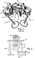
- Figure 1 shows an example of a known desmodromic system.
- the figure shows two valves each of which is opened and closed by a respective pair of rocker arms which are in turn driven by opening and closing cams on a common cam shaft.
- the closing rocker arms are fitted with torsion springs acting around the axis of the closing rocker arms.
- helper springs which are used to suppress rattle noise and do not provide any significant closing biasing force on the valves.
- JP 63-132808 shows a desmodromic valve system which uses a spring, to help close the valve, that acts in parallel with the cam forces.
- EP 2198129 shows a desmodromic valve actuation mechanism in which a valve actuator exerts a closing force on a valve stem through an elastic washer which helps to ensure that the valve, when closed, is sealed against its seat.
- the washer is carried on the actuator so that the latter does work on the washer only when the valve is closed.
- the mechanism uses a complex linkage for connecting the actuator to the engine output and various tolerances in that mechanism, and the fact that the valve, in effect, floats on the washer means that the actuator movement must be tightly constrained.
- the cylinder head of the engine is formed with an integral guide for the actuator, thus further increasing weight and complexity of the system.
- a desmodromic valve actuation mechanism comprising an actuating member in the form of a rocker, and an assembly for coupling a valve stem to the rocker, the assembly comprising:
- the spherical bearing provides a lightweight, compact means of accommodating tolerances and packaging constraints which can lead to misalignments between, for example, the valve stem axis and cam axes, as well as translational offsets and angular errors.
- the assembly is so configured that, in use, the valve is opened by movement of the assembly in an opening direction and closed by movement of the assembly in a closing direction, the coupling allowing further movement in the closing direction, against the action of the resilient arrangement, when the valve is seated.
- the assembly also provides a resilient lost motion coupling, between the valve and the rocker, that accommodates valve lash.
- the resilient arrangement comprises a resilient member which is, in use, compressed by said closing movement, when the valve is seated.
- the resilient member comprises a compression spring.
- the spherical bearing may be so configured that, in use, the rocker acts through the bearing in order to cause both opening and closing movement.
- the bearing may comprise a part spherical socket in the arm and a ball portion on a connecting rod connected, in use, to the valve stem.
- the assembly may include a further spherical bearing via which, in use, the rocker acts on the valve stem in order to open the valve.
- the further spherical bearing preferably comprises a first bearing portion having a concaved, part spherical, preferably substantially hemispherical surface, and a second bearing portion, having a complementary surface at the end of the valve stem opposite the valve head.
- the assembly further comprises a connecting rod for attachment to the rocker, and a cradle which is mounted on the rod and which carries one of the portions of the first said spherical bearing, said cradle being arranged to rock, relative to the valve stem, as said rod is moved by the rocker.
- the resilient arrangement may conveniently comprise a disc spring which is positioned so as to surround the valve stem in use.
- the disc spring may be a Bellville washer.
- the cradle allows the rod to be pivotally connected to the rocker, since the pivotal movement of the rocker and rod can then transmit linear movement to the valve stem.
- the assembly includes adjustment means for adjusting the position of the cradle on the rod, and hence the preload in the resilient arrangement when the valve is unseated.
- the resilient arrangement may, in use, be interposed between the rod at its opposite end region and the rocker, so that the rocker acts on the rod through the resilient arrangement to cause the closing movement of the assembly.
- the resilient arrangement comprises a compression spring.
- This location of the resilient arrangement allows a preload adjuster to be situated at an easily accessible position (i.e. at the region of the rod opposite the valve stem).
- the assembly includes a connecting rod for connecting a valve stem to the rocker, wherein the connecting rod is coupled to the rocker through said assembly.
- the desmodromic valve actuation mechanism is for an internal combustion engine, the mechanism further comprising an inlet or exhaust valve; an actuator for opening and closing the valve, the actuator having a rocker coupled to the valve through the assembly.
- the invention also lies in an internal combustion engine having such a desmodromic valve actuation mechanism and in an automobile fitted with such an engine.
- the sperical bearing of the assembly allows relative rotational motion between the valve stem and the actuating member.
- An assembly which gives the required valve seating force when the valve is in the closed position but does not impose a force related to that valve seating force upon the entire valve mechanism when the valve is not on the seat. It includes a means of compensating for dimensional tolerances in components and changes in dimensions due to thermal expansion and contraction.
- Lash is provided together with spring loading within the mechanism, as opposed to the known arrangements in which a spring load which is "grounded" to the engine structure.
- valves 2 and 4 each of which may comprise an inlet valve or an outlet valve having valve stems, respectively referenced 6 and 8.
- Each valve is opened and closed by actuating members in the form of a respective pair of rocker arms.
- the mechanism of which the valve 4 is a part is identical to that for the valve 2, and only the latter will therefore be described.
- the arms include an opening arm 10 having an outward end which can bear against the end of the valve stem 6 (opposite the valve head) and which is provided with a sleeve 12 for rotatably mounting the arm on a corresponding spindle (not shown).
- the other end 14 of the arm is acted on by an opening cam 16 on a cam shaft 18 which is driven by the engine crank shaft (to which it is connected by a suitable mechanism).
- a collar 18 is fixed to the upper region of the stem 6 (at a position spaced from the upper end of the stem) and cooperates with a closing arm 20 which also has a sleeve 22 for a corresponding spindle.
- the end of the arm 20 opposite the collar 18 is acted on by a closing cam 24.
- the cams 16 and 24 alternately pivot the arm 10 in an anti-clockwise direction and the arm 20 in a clockwise direction to open and close the valve 2.
- the mechanism does include a helper spring 26, but this functions merely to suppress rattle in the system, and does not provide any resilience or play in the coupling between the lever 20 and the valve 2.
- a valve head 28 is shown when against a seat 30 so that the stem (reference 32) and hence the cam follower (which may be a lever or rocker) 34 at the end of the stem 32 is incapable of any further closing movement.
- the follower 34 although bearing against an opening cam 36 is spaced from the closing cam 38 by a small distance, the clearance between the follower and the closing cam being shown at 40 and constituting the valve lash.
- a compression spring 42 acting between the valve and its mounting biases the valve into its closed position.
- this spring acts in parallel with the forces exerted by the cams 36 and 38, so that the actuator that drives the opening cam 36 has to do work on the spring 42 over the course of the entire opening movement of the valve.
- the spring 42 In order to be of the required strength, the spring 42 also needs to be relatively massive, and this adds to the inertia in the system.
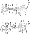
- the two valve actuation mechanisms shown in Figure 3 are substantially identical to each other, and are generally indicated by the reference numerals 44 and 46.
- the mechanism 46 is rotated about a vertical axis through 180° compared to the mechanism 44, so that the Figure shows opposite sides of the mechanisms 44 and 46. Since the mechanisms are identical, only the mechanism 46 will be described in detail, and components of the mechanism 44 will be denoted by the same reference numerals as are used in respect of the mechanism 46.
- Each mechanism includes a valve having a valve head 48 formed at one end of a valve stem 50.
- a cradle in the form of a stirrup 52 At the other end region of the stem 50 is a cradle in the form of a stirrup 52.
- the stirrup 52 has an annular base 54 which defines a central aperture 56 through which the stem 50 extends.
- the aperture 56 is of a greater diameter than the stem 50 so that, in use, the stirrup 52 can rock relative to the valve stem 50.
- the upper surface of the annular base 54 carries a washer 58 which supports the radial outer, lower edge of a Bellville spring washer 60.
- the washer 58 and Bellville 60 both surround the valve stem 50, and the inner periphery, referenced 62, and hence the upper edge of the Bellville 60 bears against an annular shoulder 64 of a lower portion 66 of a spherical bearing 68.
- the lower portion 66 is annular, and has a concaved generally upwardly facing part spherical surface 71 which bears against a complementary, convexed, part spherical, generally downward facing surface 70 of an annular upper bearing portion 72.
- the valve stem 50 also extends through the upper and lower bearing portions 72 and 66, and includes at its upper region an annular radial recess 74 for receiving valve cotters 76 for locating the upper bearing portion 72 on the stem (both axially and angularly).
- the top portion of the stem 50 is situated approximately centrally within a cage defined by the base 54 of the cradle, an annular top 78 of the cradle and axial connecting bars, for example the bar 80 which are formed integrally with the base 54 and top 78 and extend from the top to the base of the cradle.
- the top of the valve stem has a convex, generally hemispherical surface 82 which can engage a complementary generally hemispherical concave bearing surface 83 at the base of a connecting rod 84.
- the surfaces 82 and 83 provide a further spherical bearing through which, in use, the opening force is exerted on the valve stem 50.
- the surfaces 70, 71 and 82 have radii of curvature which share the same centre to avoid kinematic errors from causing the rotations permitted by the two bearings to "fight".
- the rod 84 extends into the stirrup 52 through a screw threaded bore 86 in the top of the stirrup.
- the screw threaded bore 86 cooperates with a correspondingly externally screw threaded portion of the rod 87 so that rotation of the stirrup 52 about the axis of the rod 84 varies the distance by which the rod 84 projects into the stirrup 52.
- the externally screw threaded portion 87 of the rod 84 also carries a locking nut 88 which can be tightened against the top 78 of the stirrup 52 to prevent rotation of the stirrup 52 relative to the rod 84, and hence set the distance by which the rod 84 projects into the stirrup 52.
- the top of the rod 84 is pivotally attached, at pivot joint 90 to an actuating member which is in the form of a rocker 92.
- the rod 84 is hollow and is of a two part construction, having an outer sleeve 94 to which an upper connector 96 is attached.
- the connector 96 is cylindrical and is screw threaded at its upper portion 98. This portion extends into a correspondingly screw threaded socket 100 forming part of the pivot joint 90.
- the extent by which the portion 98 may extend into the socket 100 can be varied, during assembly of the mechanism, by rotating the rod 84 about its axis. This provides adjustment for the effective rod length, i.e. the distance between the axis of the pivot joint 90 and the lower surface 83 of the rod 84.
- a locking nut 102 can be tightened against the lower edge of the socket 100 to prevent further rotation of the rod 84.
- the rocker 92 is pivotally mounted on a rocker shaft 104 and carries a roller follower 106 for an opening cam 108.
- the roller 106 is mounted on a plate 110 constituting the main body of the rocker 92.
- an arm also attached to this plate is an arm, the end of which carries a roller follower 112 which cooperates with a closing cam 114.
- the arm is behind the plate 110, but can be seen at 116 in Figure 4 .
- the corresponding arm on the rocker of the mechanism 44 is also denoted by the reference numeral 116 in Figure 3 .
- Arm 116 is rotationally mounted on the shaft 104, but is fixed to the plate 110 in such a way that, in use, the cams 108 and 114 cause a unitary rocking motion of the rocker 92 about the shaft 104.
- Opening and closing cams 108 and 114 are mounted on a common shaft which may be connected by a suitable mechanical linkage to the engine crankshaft or, preferably, to an electromagnetic actuator such as is described in WO 2004/097184 and WO 2011/061528 .
- the actuator rotates the opening and closing cams 108 and 114 in unison, as a result of which the opening cam 108 will periodically (once per revolution) push down on the roller 106, causing the rocker 92 to rotate about the shaft 104 in an anti-clockwise direction (as viewed from Figure 5 ).
- the rocker thus pushes down on the rod 84 and also rotates the latter in an anti-clockwise direction about the pivot 90.
- This causes the lower end of the rod 84 to be urged against the top of the valve stem 50 and to push down on the latter whilst also causing the stirrup 52 to rotate (about the top of the valve stem) in an anti-clockwise direction as the stem 50 moves downwards and the valve therefore opens.
- the large radius portion of the closing cam 114 is angularly spaced by 180° from the corresponding portion of the cam 108 so that the cam 114 operaes in antiphase relative to the cam 108.
- the cam 114 will begin bearing against the follower 112, causing the rocker 92 to rotate in an anti-clockwise direction thereby to raise, and thus close, the valve.
- the rod 94 and stirrup 52 move in a clock-wise direction. The valve will reach its seat before these movements of the rocker, rod and stirrup are completed.
- the stirrup 52 will continue to rise, thereby lifting the surface 83 of the rod away from the surface 82 of the valve stem, whilst the base 54 moves up towards the portions 72 and 66 of the bearing 68, and thus causes the Bellville 60 to be compressed.
- the Bellville 60 will exert a closing biasing force (typically 100 Newtons) on the valve in order to seal it against its seat.
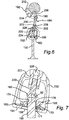
- Figure 6 shows a valve actuation mechanism in which a valve actuating member is coupled to a valve through an assembly which also includes a stirrup in which the resilience in the coupling is provided.
- the mechanism has many features which are the same as or very similar to the features of the first embodiment of mechanism, and these are therefore denoted by the reference numerals used in Figures 3-5 and 11 , raised by 100.
- a rocker 192 has roller followers 212 and 206 which respectively engage closing and opening cams (which have been omitted from the Figure) to cause the rocker to undergo angular oscillations about a shaft 204. These oscillations are transmitted through a pivot 190 to a rod 184 which is attached to a stirrup 152 which acts on the valve stem 150 through a Bellville 160 and spherical bearing 168.
- the mechanism shown in Figure 6 differs from that of Figures 3-5 and 11 in the construction of the rod 184 and the way in which it is mounted on the stirrup 152. More specifically, whereas the first embodiment used a screw threaded portion 98 at the top of the rod 94 and a correspondingly threaded socket at the pivot 90 for lash adjustment, this adjustment in the arrangement of Figure 6 is achieved using a cupped insert 220 which is at the bottom of the rod 184 and has a screw thread through which it is adjustably connected to a sleeve 222 forming part of the rod assembly. The screw threaded portion of the insert 220 also carries a locking nut 224 that can be tightened against the sleeve 222 in order to lock the insert 220 at a selected position, corresponding to a selected amount of lash.
- the rod assembly 184 is connected to the stirrup 152 through a pivot 226.
- the pivot 226 is, strictly speaking, not necessary for the required movements of the rod assembly, stirrup and valve stem relative to each other to be accommodated, but can in some circumstances facilitate assembly of the mechanism.
- the upper end of the sleeve 222 also houses an internally screw threaded portion which receives a correspondingly screw threaded end 228 of a bar 230 of the rod assembly 184.
- the screw threaded connection between the bar 230 and sleeve 222 enables the position of the stirrup 152 relative to the stem 150 when the valve is closed to be adjusted, and hence provides a means of setting the valve preload (the force exerted by the Bellville 160 on the bearing 168 when the valve is not seated).
- the desired preload is then set by tightening a locking nut 232 also carried on the screw threaded portion 228, against the top of the sleeve 222.
- the third embodiment uses a double Bellville 260 acting between the washer 258 and the lower portion 266 of the spherical bearing 268.
- Figures 8 and 9 also show, at 231, a part of the cylinder head to which the valve extends.
- the seat for the valve is shown at 233.
- an actuating member in the form of a rocker 400 is coupled to a valve stem 402 by a coupling assembly 404 in which a connecting rod 406 is pivotally attached at one end to the valve stem 404 and connected at the other end to the rocker 400 through a spherical bearing 408.
- the mechanism is operable to move the head, referenced 412 of the valve from the closed position shown in Figure 12 , in which the valve is sealed against its seat 414 in the cylinder head 416 to the open position shown in Figure 13 , in which the valve head 412 is clear of the seat 414.
- the coupling assembly is attached to the valve stem by means of a connector comprising an internally screw threaded lower sleeve 418 the top of which is connected to a plate 420 through which a pivot pin 422 extends pivotally to mount a socket portion 424 on the sleeve 418.
- the socket portion is internally screw threaded and co-operates with a correspondingly screw threaded portion on the outer surface of the lower region of the rod 406 to hold the rod in position relative to the socket 424. It will be appreciated that there are other ways in which the rod 406 may be attached to the socket 424 (for example by means of welding).
- the upper region of the rod is also screw threaded and receives a link arm adjuster nut 426 and an associated locking nut 428.
- the nut 426 can be moved up and down the upper portion of the shaft to determine the minimum distance between the bearing 408 and the top of the valve stem 402 (i.e. the distance when the valve is opened), and the locking nut can be tightened against the adjustment nut to retain the latter in position once the appropriate minimum distance has been set.
- the spherical bearing 408 includes a ball portion 430 which is held captive within a correspondingly shaped, i.e. part spherical, socket portion 432 on an arm 434 integrally formed with the rocker 400.
- the socket portion 432 has the same radius of curvature, and is concentric with, the ball portion 432 so that the ball portion 430 can rotate about its centre of curvature within the socket 432 whilst being held captive within the latter.
- Figures 12 and 13 are partially sectioned, at the spherical bearing, and it can be seen that the ball portion 430 has a central passage through which the rod 406 extends, and the top of the rod 406 projects beyond the arm 434.
- the top region 438 is externally screw threaded, and carries a pre-load adjustment mat 440.
- a coil compression spring 442 acts between a washer 444 just underneath the nut 440 and a stop 446 borne by the top of the ball portion 430.
- the rocker 434 has a similar function to the rockers of the other embodiments, and is hence mounted for angular oscillations about a rocker shaft 450 and carries a roller follower 452 which co-operates with a closing cam 454 and a further roller follower 456 which co-operates with an opening cam 458.
- the ball portion 430 can slide relative to the rod 406, and can accommodate the relative rotational movements of the rod 406 and rocker 434. However, since the ball portion 430 is held captive within the socket 432, the rocker 434 is able to continue its angular travel in the closing direction (i.e. anti-clockwise as viewed in Figures 12 and 13 ) after the valve 412 is sealed against the seat 414. This further movement of the rocker causes the ball 430 to ride up the rod 406, thus compressing the spring 442 and permitting valve lash which is manifested in the assembly as a gap 460 between the nut 426 and the underside of the ball portion 430.
- the cam 458 acts through the roller follower 456 to rotate the rocker 400 in the opposite direction.
- the ball portion 430 slides down along the rod 406, reducing the compression on the spring 442 until the ball portion 430 meets the nut 426.
- Continuing clockwise movement of the rocker 400 then moves the valve into the open position as shown in Figure 13 .
- the extent by which the valve is opened by this movement is governed by the position of the nut 426, and the position of the nut 440, when the valve is opened, governs the amount of pre-load on the spring 442 (i.e. the biasing force at that stage exerted by the spring 442 between the ball portion 430 and the nut 440).
- the spring 442 can have a much lower spring rate than the Bellville washers of the other embodiments, and can thus provide improved consistency of seat load.
- the pre-load exerted by the spring 442 can be easily adjusted, in view of the lower spring rate, and the fact that the spring and adjustment nut are now located at the top of the rod 406.
- the spherical bearing and spring arrangement shown in Figures 12-14 also facilitates the assembly of the mechanism, since the valve and lower pivotal connection at 422 can be assembled before the actuator is mounted on the engine.
- the rod 406 can be coupled to the lever 434 as the rocker is mounted and bolted down. Once this is done, the stop 446, spring 442, washer 444 and nut 440 can be mounted on the rod and bearing.
- the passage 536 through the ball portion 530 has a lower, narrow portion 531 and an upper, enlarged portion 533. These two portions meet at a step 535 which acts as a seat for the compression spring 542, the lower end of which is thus accommodated within the ball portion 530.
- the ball portion 530 is integrally formed with a cylindrical neck portion 537 which extends, coaxially with the rod 506, upwardly from the body of the ball 530 to define an extension to the wider portion of the passage 536.
- the neck portion acts as a guide for the compression spring 542, and the top of the compression spring 542 bears against a retaining collet 539 which is clamped into a circumferential recess 541 at the region at the top of the stem 506.
- the neck 537 is externally screw threaded, and retains a cap nut 543 which has a thread that very closely fits the thread on the neck 537 to provide a relatively stiff screw threaded connection between the cap 543 and the neck 537.
- the top of the cap 543 includes a screw threaded bore which receives a correspondingly screw threaded shaft 545.
- the bottom of the shaft 545 bears against the top of the rod 506, so that the distance by which the shaft 545 extends into the cap nut 543, and the spring rate of the spring 542, will determine the amount of spring pre-load on the mechanism. This can be adjusted by rotating the shaft 545 using a screwdriver (not shown) which may engage in a slot 547 at the top of the shaft 545. Once the desired pre-load has been selected, the shaft 545 can be locked in position by means of a locking nut 549.
- the spring 542 urges the rod 506 upwardly, relative to the spherical bearing, thus urging the top of the rod 506 against the bottom of the shaft 545 with a force which corresponds to the pre-load.
- the valve is in its closed position, further “closing" movement of the rocker 500 will cause the shoulder 535 to move towards the top of the rod 506 (which cannot be raised any more because the valve is seated), thus compressing the spring 542 and causing clearance at 560 between the bottom of the shaft 545 and the top of the rod 506.
- the length adjustment mechanism for adjusting the effective length between the centre of the ball portion 530 and the pivotal connection 522 is no longer provided in the region of the arm 534, but is instead achieved by means of a screw threaded lower portion of the rod 506 (denoted by reference numeral 551) which enables the rod 506 to be screwed into the connector socket 524 to a varying degree, the selected position being set by means of a length adjustment lock nut 553.
- the valves shown in Figures 3 to 5 slide in guides which are not shown. Both the opening and closing cams are mounted on the same shaft and are offset from each other along the shaft axis - see Figure 4 .
- a single rocker per valve features 2 roller followers and one roller bears upon each cam lobe; the lobe profiles themselves are not shown but simply represented by their swept circles.
- the pull-push rods are pivoted to the rockers and push directly on a hemispherical end on the valve stem.
- the "pull" function of the pull-push rod is achieved by means of an attachment to a cradle, which may or may not be free to pivot on the pull-push rod and which fits underneath a valve retaining collar fixed to the valve stem by means of conventional valve cotters.
- FIG. 7 shows an expanded view of the Cradle assembly.
- valve lash adjuster ( Figures 6 and 7 ) should be slackened off and set to provide excessive clearance in order not to interfere with the valve seat preload adjustment.
- the cam position In order to set the seating load, the cam position should first be set onto the base circle of the valve closed position.
- the Seat Pre-load adjuster, Figure 6 should be in a position which gives clear backlash in the system (as would be felt at the rocker).
- the adjuster is then rotated until the backlash has been just taken up i.e. the disc spring is just clamped but not loaded.
- the adjuster should then be rotated by a pre-determined angle which will be a function of the thread pitch in order to apply a specific compression to the spring.
- valve lash adjustment can now be made using the other adjuster and, in the design as is, can be made by "angle of turn” if there is no access for feeler gauges.
- a correctly set up mechanism will have lash selected so that, as the engine warms up and different components expand by different amounts, the situation where the valve is jacked up off the seat because the push rod is "too long" does not arise.
- the seating load will vary as the engine warms up but, correctly designed, will always stay within acceptable limits.
- the mechanism achieves the seating load by the application of, in effect, a "negative lash” adjustment in the closing cam mechanism - but this negative lash does not give rise to excessive loads because the disc spring can accommodate variation in the negative lash without imposing excessive loads onto the system or allowing it to lock up by going "solid".
- the maximum compression of the disc spring can be limited by ensuring the Spring Retainer spigot which locates the ID of the disc spring is long enough to contact the spring seating surface in the cradle at the appropriate compression.
- the spring element is a disc spring in the embodiments described above, it will be appreciated that the required resilience may be achieved using other resilient assemblies or components.
- the spherical bearing at the valve retainer should have the same centre as the spherical radius on the end of the valve - otherwise there will be a kinematic error and the two rotations will conflict with each other.
Landscapes
- Engineering & Computer Science (AREA)
- General Engineering & Computer Science (AREA)
- Mechanical Engineering (AREA)
- Valve-Gear Or Valve Arrangements (AREA)
- Mechanically-Actuated Valves (AREA)
Description
- This invention relates to an assembly for coupling a valve stem to an actuating member of an actuator in a desmodromic valve actuation mechanism, to a desmodromic valve actuation mechanism having such an assembly and to an internal combustion engine having such a desmodromic valve actuation mechanism. The invention also lies in a vehicle, such as an automobile, fitted with such an internal combustion engine.
- Desmodromic valve systems for engine inlet and exhaust valves are well known and a sub-set of these mechanisms using a combined pull-push rod to actuate a valve is also long-established. Traditionally, these mechanisms have left a certain amount of lash between the opening and closing parts of the mechanism in order to avoid potential "fight" between the two actions arising either from tolerance errors or by changes in component dimensions with temperature. Such an eventuality could lead to rapid wear of the mechanism or a catastrophic failure due to the mechanism locking up. An exhaust valve can "grow" by 0.15mm quite easily at full load.
- Common past practice was to positively close the valve to within a few thousandths of an inch of the seat and then allow cylinder pressure to do the rest.
Figure 1 shows an example of a known desmodromic system. The figure shows two valves each of which is opened and closed by a respective pair of rocker arms which are in turn driven by opening and closing cams on a common cam shaft. As can be seen from the figure, the closing rocker arms are fitted with torsion springs acting around the axis of the closing rocker arms. However, these are helper springs which are used to suppress rattle noise and do not provide any significant closing biasing force on the valves. - More recently, emissions regulations have made this approach impractical and the valve now has to be closed using spring force. Ducati engine designs (using desmodromic valve systems) use a spring not dissimilar in terms of spring force from a conventional spring for this purpose. The issue here is that these springs act in parallel with the cam forces so the opening cam has to provide enough force to compress the spring as well as to accelerate the valve mass (see
Figure 2 ). This is a disadvantage because it increases the loads in the system and therefore the stresses, the system mass and the parasitic losses. -
JP 63-132808 - This approach is also unsuitable for independent valve actuation mechanisms in which, instead of a mechanical linkage between the engine output, an electromagnetic actuator is used.
- For example in the case of the present applicant's electromagnetic valve actuation systems (as described in
WO 2004/097184 andWO2011/061528 ), the additional torque required of the actuator in order to compress a spring in parallel with the valve mass is doubly undesirable. Not only would it require a significantly larger electrical actuator but the electrical energy demand would also be significantly increased, at the expense of the overall efficiency of an engine fitted with such a mechanism. -
EP 2198129 (Pattakos) shows a desmodromic valve actuation mechanism in which a valve actuator exerts a closing force on a valve stem through an elastic washer which helps to ensure that the valve, when closed, is sealed against its seat. The washer is carried on the actuator so that the latter does work on the washer only when the valve is closed. However the mechanism uses a complex linkage for connecting the actuator to the engine output and various tolerances in that mechanism, and the fact that the valve, in effect, floats on the washer means that the actuator movement must be tightly constrained. - To that end the cylinder head of the engine is formed with an integral guide for the actuator, thus further increasing weight and complexity of the system.
- According to a first aspect of the invention, there is provided a desmodromic valve actuation mechanism comprising an actuating member in the form of a rocker, and an assembly for coupling a valve stem to the rocker, the assembly comprising:
- a spherical bearing having two portions each of which defines a respective bearing surface which is complementary to the bearing surface defined by the other portion, at least one of the surfaces being part spherical, one of the portions being arranged to be coupled to the rocker and the other portion being arranged to be coupled to the valve stem; characterised in that the assembly includes
- a resilient arrangement which exerts a biasing force on one of the bearing portions and provides resilience in the coupling provided by the assembly between the valve stem and rocker.
- The spherical bearing provides a lightweight, compact means of accommodating tolerances and packaging constraints which can lead to misalignments between, for example, the valve stem axis and cam axes, as well as translational offsets and angular errors.
- Since the resilience that urges the valve into its closed position is provided in the coupling between the valve stem and the actuating member, it is not necessary for the assembly to do significant work on the resilient arrangement when the valve is in an unseated position.
- Preferably, therefore, the assembly is so configured that, in use, the valve is opened by movement of the assembly in an opening direction and closed by movement of the assembly in a closing direction, the coupling allowing further movement in the closing direction, against the action of the resilient arrangement, when the valve is seated.
- Thus the assembly also provides a resilient lost motion coupling, between the valve and the rocker, that accommodates valve lash.
- Preferably, the resilient arrangement comprises a resilient member which is, in use, compressed by said closing movement, when the valve is seated.
- Preferably, the resilient member comprises a compression spring.
- The spherical bearing may be so configured that, in use, the rocker acts through the bearing in order to cause both opening and closing movement.
- For example, if the actuating member comprises a rocker arm, the bearing may comprise a part spherical socket in the arm and a ball portion on a connecting rod connected, in use, to the valve stem.
- Alternatively, the assembly may include a further spherical bearing via which, in use, the rocker acts on the valve stem in order to open the valve.
- In this case, the further spherical bearing preferably comprises a first bearing portion having a concaved, part spherical, preferably substantially hemispherical surface, and a second bearing portion, having a complementary surface at the end of the valve stem opposite the valve head.
- This enables the second portion to be formed integrally with the valve stem, thus facilitating a light weight, low inertia construction of assembly.
- Preferably, the assembly further comprises a connecting rod for attachment to the rocker, and a cradle which is mounted on the rod and which carries one of the portions of the first said spherical bearing, said cradle being arranged to rock, relative to the valve stem, as said rod is moved by the rocker.
- The resilient arrangement may conveniently comprise a disc spring which is positioned so as to surround the valve stem in use. For example, the disc spring may be a Bellville washer.
- The cradle allows the rod to be pivotally connected to the rocker, since the pivotal movement of the rocker and rod can then transmit linear movement to the valve stem.
- Preferably, the assembly includes adjustment means for adjusting the position of the cradle on the rod, and hence the preload in the resilient arrangement when the valve is unseated.
- This can be achieved by means of, for example, a screw threaded connection between the rod and the cradle, and provides an arrangement in which preload can be relatively easily adjusted in view of the relative accessibility of the cradle.
- Alternatively, where the assembly has a rod for connection at one end to the valve stem, the resilient arrangement may, in use, be interposed between the rod at its opposite end region and the rocker, so that the rocker acts on the rod through the resilient arrangement to cause the closing movement of the assembly.
- Preferably, in this case, the resilient arrangement comprises a compression spring.
- This location of the resilient arrangement allows a preload adjuster to be situated at an easily accessible position (i.e. at the region of the rod opposite the valve stem).
- Preferably, the assembly includes a connecting rod for connecting a valve stem to the rocker, wherein the connecting rod is coupled to the rocker through said assembly.
- Preferably, the desmodromic valve actuation mechanism is for an internal combustion engine, the mechanism further comprising an inlet or exhaust valve; an actuator for opening and closing the valve, the actuator having a rocker coupled to the valve through the assembly.
- The invention also lies in an internal combustion engine having such a desmodromic valve actuation mechanism and in an automobile fitted with such an engine.
- Preferably, the sperical bearing of the assembly allows relative rotational motion between the valve stem and the actuating member.
- An assembly is provided which gives the required valve seating force when the valve is in the closed position but does not impose a force related to that valve seating force upon the entire valve mechanism when the valve is not on the seat. It includes a means of compensating for dimensional tolerances in components and changes in dimensions due to thermal expansion and contraction.
- Lash is provided together with spring loading within the mechanism, as opposed to the known arrangements in which a spring load which is "grounded" to the engine structure.
- Embodiments of the invention will now be described, by way of example only, with reference to the accompanying drawings, in which:-
-
Figure 1 is a perspective view of two valves for a cylinder of an internal combustion engine and a known type of desmodromic valve actuation mechanism for opening and closing the valves; -
Figure 2 is a schematic view illustrating the various loads on another type of known desmodromic valve actuation mechanism; -
Figure 3 is a front elevation view of two examples of a first embodiment of valve actuation mechanism in accordance with the invention; -
Figure 4 is a side elevation view of one of the mechanisms shown inFigure 3 ; -
Figure 5 is a sectional view of the mechanisms ofFigures 3 and 4 , taken along the line A-A inFigure 4 ; -
Figure 6 is a sectional side view of a second embodiment of valve actuation mechanism in accordance with the invention; -
Figure 7 is a more detailed view of part of the mechanism ofFigure 6 ; -
Figure 8 is a partially cut away front elevation of a third embodiment of desmodromic valve actuation mechanism in accordance with the invention, and also shows part of the cylinder head (including the valve seat) in which the valve of the mechanism works, the Figure showing the mechanism when the valve is in its closed position; -
Figure 9 is a corresponding view of the mechanism when the valve is in its open position; -
Figure 10 is a more detailed cross-sectional view of the mechanism shown inFigures 8 and 9 , when the valve is in the closed position; -
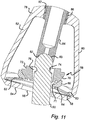
Figure 11 is a more detailed view of part of the mechanism shown inFigures 3-5 , when the valve is in an open position; -
Figure 12 is a cut away front view of a fourth embodiment of desmodromic valve actuation mechanism in accordance with the invention, the Figure also showing the portion of the cylinder head in which the valve moves and the valve seat, the mechanism being shown when the valve is in its closed position; -
Figure 13 is a corresponding view toFigure 12 , showing the mechanism when the valve is in its open condition; -
Figure 14 is a cut away front view, to an enlarged scale, of the embodiment of mechanism shown inFigures 12 and 13 ; -
Figure 15 is a cut away front view of a fifth embodiment of desmodromic valve actuation mechanism in accordance with the invention, also showing a portion of the cylinder head in which the valve moves, the mechanism being shown when the valve is closed; -
Figure 16 is a corresponding view toFigure 15 , showing the mechanism when the valve is open; and -
Figure 17 is a cut away front view, to an enlarged scale, of part of the mechanism shown inFigures 15 and 16 . - In the mechanism shown in
Figure 1 , there are two valves, referenced 2 and 4 each of which may comprise an inlet valve or an outlet valve having valve stems, respectively referenced 6 and 8. Each valve is opened and closed by actuating members in the form of a respective pair of rocker arms. The mechanism of which the valve 4 is a part is identical to that for thevalve 2, and only the latter will therefore be described. The arms include anopening arm 10 having an outward end which can bear against the end of the valve stem 6 (opposite the valve head) and which is provided with asleeve 12 for rotatably mounting the arm on a corresponding spindle (not shown). - The
other end 14 of the arm is acted on by anopening cam 16 on acam shaft 18 which is driven by the engine crank shaft (to which it is connected by a suitable mechanism). - A
collar 18 is fixed to the upper region of the stem 6 (at a position spaced from the upper end of the stem) and cooperates with aclosing arm 20 which also has asleeve 22 for a corresponding spindle. The end of thearm 20 opposite thecollar 18 is acted on by aclosing cam 24. Thecams arm 10 in an anti-clockwise direction and thearm 20 in a clockwise direction to open and close thevalve 2. When thevalve 2 is seated, it cannot be closed any further and the mechanism would therefore jam if thearm 20 had not by that point completed its clockwise stroke. To ensure this does not happen (when the system is cold) some clearance would be left between thevalve 2 and its seat (i.e. valve lash), with the valve then being closed by the pressure of combustion gases, with the associated problems previously explained. The mechanism does include ahelper spring 26, but this functions merely to suppress rattle in the system, and does not provide any resilience or play in the coupling between thelever 20 and thevalve 2. - In the system schematically shown in
Figure 2 , avalve head 28 is shown when against aseat 30 so that the stem (reference 32) and hence the cam follower (which may be a lever or rocker) 34 at the end of thestem 32 is incapable of any further closing movement. Thefollower 34, although bearing against anopening cam 36 is spaced from the closing cam 38 by a small distance, the clearance between the follower and the closing cam being shown at 40 and constituting the valve lash. Acompression spring 42 acting between the valve and its mounting (for example the engine cylinder head) biases the valve into its closed position. However, this spring acts in parallel with the forces exerted by thecams 36 and 38, so that the actuator that drives theopening cam 36 has to do work on thespring 42 over the course of the entire opening movement of the valve. In order to be of the required strength, thespring 42 also needs to be relatively massive, and this adds to the inertia in the system. - The two valve actuation mechanisms shown in
Figure 3 are substantially identical to each other, and are generally indicated by thereference numerals mechanism 46 is rotated about a vertical axis through 180° compared to themechanism 44, so that the Figure shows opposite sides of themechanisms mechanism 46 will be described in detail, and components of themechanism 44 will be denoted by the same reference numerals as are used in respect of themechanism 46. - Each mechanism includes a valve having a
valve head 48 formed at one end of avalve stem 50. At the other end region of thestem 50 is a cradle in the form of astirrup 52. As can be seen fromFigures 5 and11 , thestirrup 52 has anannular base 54 which defines acentral aperture 56 through which thestem 50 extends. Theaperture 56 is of a greater diameter than thestem 50 so that, in use, thestirrup 52 can rock relative to thevalve stem 50. The upper surface of theannular base 54 carries awasher 58 which supports the radial outer, lower edge of aBellville spring washer 60. - As can be seen from
Figures 5 and11 , thewasher 58 andBellville 60 both surround thevalve stem 50, and the inner periphery, referenced 62, and hence the upper edge of theBellville 60 bears against anannular shoulder 64 of alower portion 66 of aspherical bearing 68. Thelower portion 66 is annular, and has a concaved generally upwardly facing partspherical surface 71 which bears against a complementary, convexed, part spherical, generally downward facingsurface 70 of an annular upper bearing portion 72. - The valve stem 50 also extends through the upper and
lower bearing portions 72 and 66, and includes at its upper region an annularradial recess 74 for receivingvalve cotters 76 for locating the upper bearing portion 72 on the stem (both axially and angularly). - The top portion of the
stem 50 is situated approximately centrally within a cage defined by thebase 54 of the cradle, anannular top 78 of the cradle and axial connecting bars, for example thebar 80 which are formed integrally with thebase 54 and top 78 and extend from the top to the base of the cradle. - The top of the valve stem has a convex, generally
hemispherical surface 82 which can engage a complementary generally hemisphericalconcave bearing surface 83 at the base of a connectingrod 84. - The
surfaces valve stem 50. Thesurfaces - The
rod 84 extends into thestirrup 52 through a screw threaded bore 86 in the top of the stirrup. The screw threaded bore 86 cooperates with a correspondingly externally screw threaded portion of therod 87 so that rotation of thestirrup 52 about the axis of therod 84 varies the distance by which therod 84 projects into thestirrup 52. - The externally screw threaded
portion 87 of therod 84 also carries a lockingnut 88 which can be tightened against the top 78 of thestirrup 52 to prevent rotation of thestirrup 52 relative to therod 84, and hence set the distance by which therod 84 projects into thestirrup 52. - The top of the
rod 84 is pivotally attached, at pivot joint 90 to an actuating member which is in the form of arocker 92. As can be seen fromFigure 5 , therod 84 is hollow and is of a two part construction, having anouter sleeve 94 to which anupper connector 96 is attached. Theconnector 96 is cylindrical and is screw threaded at itsupper portion 98. This portion extends into a correspondingly screw threadedsocket 100 forming part of the pivot joint 90. The extent by which theportion 98 may extend into thesocket 100 can be varied, during assembly of the mechanism, by rotating therod 84 about its axis. This provides adjustment for the effective rod length, i.e. the distance between the axis of the pivot joint 90 and thelower surface 83 of therod 84. Once the desired length has been achieved, a lockingnut 102 can be tightened against the lower edge of thesocket 100 to prevent further rotation of therod 84. - The
rocker 92 is pivotally mounted on arocker shaft 104 and carries aroller follower 106 for anopening cam 108. Theroller 106 is mounted on aplate 110 constituting the main body of therocker 92. Also attached to this plate is an arm, the end of which carries aroller follower 112 which cooperates with aclosing cam 114. InFigure 5 the arm is behind theplate 110, but can be seen at 116 inFigure 4 . The corresponding arm on the rocker of themechanism 44 is also denoted by thereference numeral 116 inFigure 3 .Arm 116 is rotationally mounted on theshaft 104, but is fixed to theplate 110 in such a way that, in use, thecams rocker 92 about theshaft 104. - Opening and
closing cams WO 2004/097184 andWO 2011/061528 . - In use, the actuator rotates the opening and
closing cams opening cam 108 will periodically (once per revolution) push down on theroller 106, causing therocker 92 to rotate about theshaft 104 in an anti-clockwise direction (as viewed fromFigure 5 ). The rocker thus pushes down on therod 84 and also rotates the latter in an anti-clockwise direction about thepivot 90. This in turn causes the lower end of therod 84 to be urged against the top of thevalve stem 50 and to push down on the latter whilst also causing thestirrup 52 to rotate (about the top of the valve stem) in an anti-clockwise direction as thestem 50 moves downwards and the valve therefore opens. - During this movement, the Bellville remains uncompressed since it is, in effect, connected in series between the
rod 84 and thevalve stem 50. - The large radius portion of the
closing cam 114 is angularly spaced by 180° from the corresponding portion of thecam 108 so that thecam 114 operaes in antiphase relative to thecam 108. Thus, after thecam 108 has opened the valve, thecam 114 will begin bearing against thefollower 112, causing therocker 92 to rotate in an anti-clockwise direction thereby to raise, and thus close, the valve. During this movement, therod 94 andstirrup 52 move in a clock-wise direction. The valve will reach its seat before these movements of the rocker, rod and stirrup are completed. Thus, once the valve has been seated, thestirrup 52 will continue to rise, thereby lifting thesurface 83 of the rod away from thesurface 82 of the valve stem, whilst the base 54 moves up towards theportions 72 and 66 of thebearing 68, and thus causes theBellville 60 to be compressed. When thestirrup 52 is in its fully raised condition, theBellville 60 will exert a closing biasing force (typically 100 Newtons) on the valve in order to seal it against its seat. Although the mechanism has to do work on the Bellville to compress it, this only happens over a relatively short distance of movement of thestirrup 52, and thus gives rise to significantly reduced energy demands compared with a system in which the valve is biased closed by a spring connected in parallel. - As with other valve actuation mechanisms, tolerances and packaging constraints make it practically impossible to ensure that the axis of the cams intersects the valve axis, and the system may also need to be able to accommodate angular errors as well as translation offsets. The use of a spherical bearing as one of the abutments for the
Bellville 60 can accommodate these variations, whilst enabling the assembly to be of a light weight, low inertia construction. InFigure 11 , theBellville 60 is shown in its uncompressed condition in which the force exerted by theBellville 60 on thebearing 68 corresponds to the valve preload set for the mechanism in the way described above. -
Figure 6 shows a valve actuation mechanism in which a valve actuating member is coupled to a valve through an assembly which also includes a stirrup in which the resilience in the coupling is provided. The mechanism has many features which are the same as or very similar to the features of the first embodiment of mechanism, and these are therefore denoted by the reference numerals used inFigures 3-5 and11 , raised by 100. Thus arocker 192 hasroller followers shaft 204. These oscillations are transmitted through apivot 190 to arod 184 which is attached to astirrup 152 which acts on thevalve stem 150 through aBellville 160 andspherical bearing 168. - The mechanism shown in
Figure 6 differs from that ofFigures 3-5 and11 in the construction of therod 184 and the way in which it is mounted on thestirrup 152. More specifically, whereas the first embodiment used a screw threadedportion 98 at the top of therod 94 and a correspondingly threaded socket at thepivot 90 for lash adjustment, this adjustment in the arrangement ofFigure 6 is achieved using acupped insert 220 which is at the bottom of therod 184 and has a screw thread through which it is adjustably connected to asleeve 222 forming part of the rod assembly. The screw threaded portion of theinsert 220 also carries a lockingnut 224 that can be tightened against thesleeve 222 in order to lock theinsert 220 at a selected position, corresponding to a selected amount of lash. - In addition, the
rod assembly 184 is connected to thestirrup 152 through apivot 226. Thepivot 226 is, strictly speaking, not necessary for the required movements of the rod assembly, stirrup and valve stem relative to each other to be accommodated, but can in some circumstances facilitate assembly of the mechanism. - The upper end of the
sleeve 222 also houses an internally screw threaded portion which receives a correspondingly screw threadedend 228 of abar 230 of therod assembly 184. - The screw threaded connection between the
bar 230 andsleeve 222 enables the position of thestirrup 152 relative to thestem 150 when the valve is closed to be adjusted, and hence provides a means of setting the valve preload (the force exerted by theBellville 160 on thebearing 168 when the valve is not seated). The desired preload is then set by tightening a locking nut 232 also carried on the screw threadedportion 228, against the top of thesleeve 222. - The embodiment shown in
Figures 8-10 is identical to the first embodiment in all respects other than the nature of the resilient arrangement that acts through the spherical bearings. Accordingly, features that correspond to those of the first embodiment are denoted by the reference numerals ofFigures 3-5 and11 , raised by 200. - Whereas the spherical bearing of the first embodiment was acted on through a single Bellville, the third embodiment uses a
double Bellville 260 acting between thewasher 258 and thelower portion 266 of thespherical bearing 268. - In
Figure 10 , some clearance is shown between the top of thevalve stem 250 and the bottom of therod 284. This arises because the valve is in its closed condition. InFigure 11 , the stirrup part of the coupling assembly is shown also when the valve is in its closed position, but in this case there is no clearance. This is because the Figure shows the situation when the valve is hot, and has expanded to its maximum length, whereas inFigure 10 thevalve stem 250 is cooler, and therefore shorter. -
Figures 8 and 9 also show, at 231, a part of the cylinder head to which the valve extends. The seat for the valve is shown at 233. - In the embodiment shown in
Figures 12-14 , an actuating member in the form of arocker 400 is coupled to avalve stem 402 by acoupling assembly 404 in which a connectingrod 406 is pivotally attached at one end to thevalve stem 404 and connected at the other end to therocker 400 through aspherical bearing 408. The mechanism is operable to move the head, referenced 412 of the valve from the closed position shown inFigure 12 , in which the valve is sealed against itsseat 414 in thecylinder head 416 to the open position shown inFigure 13 , in which thevalve head 412 is clear of theseat 414. - The coupling assembly is attached to the valve stem by means of a connector comprising an internally screw threaded
lower sleeve 418 the top of which is connected to aplate 420 through which apivot pin 422 extends pivotally to mount asocket portion 424 on thesleeve 418. The socket portion is internally screw threaded and co-operates with a correspondingly screw threaded portion on the outer surface of the lower region of therod 406 to hold the rod in position relative to thesocket 424. It will be appreciated that there are other ways in which therod 406 may be attached to the socket 424 (for example by means of welding). - The upper region of the rod is also screw threaded and receives a link
arm adjuster nut 426 and an associatedlocking nut 428. Thenut 426 can be moved up and down the upper portion of the shaft to determine the minimum distance between the bearing 408 and the top of the valve stem 402 (i.e. the distance when the valve is opened), and the locking nut can be tightened against the adjustment nut to retain the latter in position once the appropriate minimum distance has been set. - The
spherical bearing 408 includes aball portion 430 which is held captive within a correspondingly shaped, i.e. part spherical,socket portion 432 on anarm 434 integrally formed with therocker 400. Thesocket portion 432 has the same radius of curvature, and is concentric with, theball portion 432 so that theball portion 430 can rotate about its centre of curvature within thesocket 432 whilst being held captive within the latter.Figures 12 and 13 are partially sectioned, at the spherical bearing, and it can be seen that theball portion 430 has a central passage through which therod 406 extends, and the top of therod 406 projects beyond thearm 434. Thetop region 438 is externally screw threaded, and carries apre-load adjustment mat 440. Acoil compression spring 442 acts between awasher 444 just underneath thenut 440 and astop 446 borne by the top of theball portion 430. - The
rocker 434 has a similar function to the rockers of the other embodiments, and is hence mounted for angular oscillations about arocker shaft 450 and carries aroller follower 452 which co-operates with aclosing cam 454 and afurther roller follower 456 which co-operates with anopening cam 458. - The
ball portion 430 can slide relative to therod 406, and can accommodate the relative rotational movements of therod 406 androcker 434. However, since theball portion 430 is held captive within thesocket 432, therocker 434 is able to continue its angular travel in the closing direction (i.e. anti-clockwise as viewed inFigures 12 and 13 ) after thevalve 412 is sealed against theseat 414. This further movement of the rocker causes theball 430 to ride up therod 406, thus compressing thespring 442 and permitting valve lash which is manifested in the assembly as agap 460 between thenut 426 and the underside of theball portion 430. Once therocker 400 has passed through the maximum angle in the anti-clockwise direction, thecam 458 acts through theroller follower 456 to rotate therocker 400 in the opposite direction. Initially, theball portion 430 slides down along therod 406, reducing the compression on thespring 442 until theball portion 430 meets thenut 426. Continuing clockwise movement of therocker 400 then moves the valve into the open position as shown inFigure 13 . The extent by which the valve is opened by this movement is governed by the position of thenut 426, and the position of thenut 440, when the valve is opened, governs the amount of pre-load on the spring 442 (i.e. the biasing force at that stage exerted by thespring 442 between theball portion 430 and the nut 440). - The
spring 442 can have a much lower spring rate than the Bellville washers of the other embodiments, and can thus provide improved consistency of seat load. In addition, the pre-load exerted by thespring 442 can be easily adjusted, in view of the lower spring rate, and the fact that the spring and adjustment nut are now located at the top of therod 406. The spherical bearing and spring arrangement shown inFigures 12-14 also facilitates the assembly of the mechanism, since the valve and lower pivotal connection at 422 can be assembled before the actuator is mounted on the engine. Therod 406 can be coupled to thelever 434 as the rocker is mounted and bolted down. Once this is done, thestop 446,spring 442,washer 444 andnut 440 can be mounted on the rod and bearing. - The embodiment of mechanisms shown in
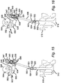
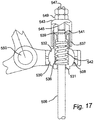
Figures 15-17 is similar in many respects to that shown inFigures 12-14 , and corresponding features are therefore denoted by the reference numerals ofFigures 12-14 raised by 100. - In the embodiments shown in
Figures 15-17 , thepassage 536 through theball portion 530 has a lower,narrow portion 531 and an upper,enlarged portion 533. These two portions meet at astep 535 which acts as a seat for thecompression spring 542, the lower end of which is thus accommodated within theball portion 530. - The
ball portion 530 is integrally formed with acylindrical neck portion 537 which extends, coaxially with therod 506, upwardly from the body of theball 530 to define an extension to the wider portion of thepassage 536. The neck portion acts as a guide for thecompression spring 542, and the top of thecompression spring 542 bears against a retainingcollet 539 which is clamped into acircumferential recess 541 at the region at the top of thestem 506. Theneck 537 is externally screw threaded, and retains acap nut 543 which has a thread that very closely fits the thread on theneck 537 to provide a relatively stiff screw threaded connection between thecap 543 and theneck 537. The top of thecap 543 includes a screw threaded bore which receives a correspondingly screw threadedshaft 545. When the valve is opened, the bottom of theshaft 545 bears against the top of therod 506, so that the distance by which theshaft 545 extends into thecap nut 543, and the spring rate of thespring 542, will determine the amount of spring pre-load on the mechanism. This can be adjusted by rotating theshaft 545 using a screwdriver (not shown) which may engage in aslot 547 at the top of theshaft 545. Once the desired pre-load has been selected, theshaft 545 can be locked in position by means of a lockingnut 549. - When the valve is in its open position, for example as shown in
Figure 16 , thespring 542 urges therod 506 upwardly, relative to the spherical bearing, thus urging the top of therod 506 against the bottom of theshaft 545 with a force which corresponds to the pre-load. When the valve is in its closed position, further "closing" movement of therocker 500 will cause theshoulder 535 to move towards the top of the rod 506 (which cannot be raised any more because the valve is seated), thus compressing thespring 542 and causing clearance at 560 between the bottom of theshaft 545 and the top of therod 506. In theFigures 15-18 embodiment, the length adjustment mechanism for adjusting the effective length between the centre of theball portion 530 and thepivotal connection 522 is no longer provided in the region of thearm 534, but is instead achieved by means of a screw threaded lower portion of the rod 506 (denoted by reference numeral 551) which enables therod 506 to be screwed into theconnector socket 524 to a varying degree, the selected position being set by means of a lengthadjustment lock nut 553. - The valves shown in
Figures 3 to 5 slide in guides which are not shown. Both the opening and closing cams are mounted on the same shaft and are offset from each other along the shaft axis - seeFigure 4 . A single rocker per valve features 2 roller followers and one roller bears upon each cam lobe; the lobe profiles themselves are not shown but simply represented by their swept circles. The pull-push rods are pivoted to the rockers and push directly on a hemispherical end on the valve stem. The "pull" function of the pull-push rod is achieved by means of an attachment to a cradle, which may or may not be free to pivot on the pull-push rod and which fits underneath a valve retaining collar fixed to the valve stem by means of conventional valve cotters. - When the closing cam exerts a force on the pull-push rod this is transmitted to the cradle by the cradle pivot pin and the cradle pulls the valve back towards its seat through a compact spring loaded mechanism and a spherical bearing which allows the cradle to rock relative to the valve stem.
Figure 7 shows an expanded view of the Cradle assembly. - The mechanism may need to be adjusted in order to function correctly. Initially the valve lash adjuster (
Figures 6 and 7 ) should be slackened off and set to provide excessive clearance in order not to interfere with the valve seat preload adjustment. In order to set the seating load, the cam position should first be set onto the base circle of the valve closed position. The Seat Pre-load adjuster,Figure 6 , should be in a position which gives clear backlash in the system (as would be felt at the rocker). The adjuster is then rotated until the backlash has been just taken up i.e. the disc spring is just clamped but not loaded. The adjuster should then be rotated by a pre-determined angle which will be a function of the thread pitch in order to apply a specific compression to the spring. This compression, calculated in combination with the spring rate, will provide the desired valve seating load under the nominal adjustment conditions and the adjuster can now be locked by means of the locknut. This done, the valve lash adjustment can now be made using the other adjuster and, in the design as is, can be made by "angle of turn" if there is no access for feeler gauges. - Thus, a correctly set up mechanism will have lash selected so that, as the engine warms up and different components expand by different amounts, the situation where the valve is jacked up off the seat because the push rod is "too long" does not arise. The seating load will vary as the engine warms up but, correctly designed, will always stay within acceptable limits.
- The mechanism achieves the seating load by the application of, in effect, a "negative lash" adjustment in the closing cam mechanism - but this negative lash does not give rise to excessive loads because the disc spring can accommodate variation in the negative lash without imposing excessive loads onto the system or allowing it to lock up by going "solid".
- If required, the maximum compression of the disc spring can be limited by ensuring the Spring Retainer spigot which locates the ID of the disc spring is long enough to contact the spring seating surface in the cradle at the appropriate compression.
- Although the spring element is a disc spring in the embodiments described above, it will be appreciated that the required resilience may be achieved using other resilient assemblies or components.
- The spherical bearing at the valve retainer should have the same centre as the spherical radius on the end of the valve - otherwise there will be a kinematic error and the two rotations will conflict with each other.
Claims (21)
- A desmodromic valve actuation mechanism comprising an actuating member in the form of a rocker (92; 192; 392; 400; 500) and an assembly for coupling a valve stem (50; 150; 250; 402; 502) to the rocker (92; 192; 392; 400; 500), the assembly comprising:a spherical bearing (68; 168; 268; 408; 508) having two portions (70, 71; 170, 171; 430, 432) each of which defines a respective bearing surface which is complementary to the bearing surface defined by the other portion, at least one of the surfaces being part spherical, one of the portions being arranged to be coupled to the rocker (92; 192; 392; 400; 500) and the other portion being arranged to be coupled to the valve stem; characterised in that the assembly includesa resilient arrangement (60; 160; 260; 442; 542) which exerts a biasing force on one of the bearing portions and provides resilience in the coupling provided by the assembly between the valve stem (50; 150; 250; 402; 502) and rocker (92; 192; 392; 400; 500).
- A desmodromic valve actuation mechanism according to claim 1, in which the assembly is so configured that, in use, the valve (48; 248; 412; 512) is opened by movement of the assembly in an opening direction and closed by movement of the assembly in a closing direction, the coupling allowing further movement in the closing direction, against the action of the resilient arrangement, when the valve is seated.
- A desmodromic valve actuation mechanism according to claim 1 or claim 2, in which one of the bearing surfaces (70; 170, 430; 530) is part spherical and convex, the other of the bearing surfaces (71; 171; 432; 532) being part spherical and concave.
- A desmodromic valve actuation mechanism according to any of the preceding claims, in which the assembly provides a resilient lost motion connection, between the valve and the rocker (92; 192; 392; 400; 500), that accommodates valve lash.
- A desmodromic valve actuation mechanism according to any of the preceding claims, in which the resilient arrangement comprises a resilient member (60; 160; 260; 442; 542) which is, in use, compressed by said closing movement, when the valve is seated.
- A desmodromic valve actuation mechanism according to claim 5, in which the resilient member comprises a compression spring (60; 160; 260; 442; 542).
- A desmodromic valve actuation mechanism according to any of the preceding claims, in which the spherical bearing (68; 168; 268; 408; 508) is so configured that, in use, the rocker (92; 192; 392; 400; 500) acts through the bearing in order to cause both opening and closing movement.
- A desmodromic valve actuation mechanism according to claim 7, in which the bearing comprises a part spherical socket (432; 532) in the rocker (400; 500) and a ball portion (430; 530) on a connecting rod (406; 506) connected, in use to the valve stem (402; 502).
- A desmodromic valve actuation mechanism according to any of claims 1 to 6, in which the assembly includes a further spherical bearing (82, 83; 282, 283) via which, in use, the rocker (192; 392) acts on the valve stem (150; 250) in order to open the valve.
- A desmodromic valve actuation mechanism according to claim 9, in which the further spherical bearing comprises a first bearing portion (83; 283) having a concaved, part spherical surface, and a second bearing portion, having a complementary surface (82; 282) at the end of the valve stem (150; 250) opposite the valve head.
- A desmodromic valve actuation mechanism according to any of the preceding claims, in which the assembly further comprises a connecting rod (84; 184; 284) for attachment to the rocker (92; 192; 392), and a cradle (52; 152; 252) which is mounted on the rod and which carries one of the portions of the spherical bearing (68; 168; 268), said cradle being arranged to rock, relative to the valve stem (50; 150; 250), as said rod is moved by the rocker (92; 192; 392).
- A desmodromic valve actuation mechanism according to any of the preceding claims, in which resilient arrangement comprises a disc spring (60; 160; 260) which is positioned so as to surround the valve stem (50; 150; 250) in use.
- A desmodromic valve actuation mechanism according to claim 12, in which the disc spring (60; 160; 260) comprises a Bellville washer.
- A desmodromic valve actuation mechanism according to claim 11, in which the assembly includes adjustment means (86, 87; 286, 287; 222, 228) for adjusting the position of the cradle on the rod, and hence the preload in the resilient arrangement when the valve is unseated.
- A desmodromic valve actuation mechanism according to claim 14, in which the adjustment means comprises a screw threaded connection between the rod and the cradle.
- A desmodromic valve actuation mechanism according to any of claims 11, 14 or 15, in which the resilient arrangement (60; 160; 260) is, in use, interposed between the rod (84; 184; 284), at its end region remote from the region of the rod connected to the valve stem, and the actuating member, so that the actuating member (92; 192; 392) acts on the rod through the resilient arrangement to cause the closing movement of the assembly.
- A desmodromic valve actuation mechanism according to claim 16, in which the assembly includes a preload adjuster (86, 87; 268, 287; 222, 228) situated at a said end region of the rod.
- A desmodromic valve actuation mechanism according to any of the preceding claims wherein the assembly includes a connecting rod (84; 184; 284; 406; 506) for connecting a valve stem to the rocker, and wherein the connecting rod is coupled to the rocker through said assembly.
- A desmodromic valve actuation mechanism according to any of claims 1 to 7, for an internal combustion engine, the mechanism comprising an inlet or exhaust valve; an actuator for opening and closing the valve, the actuator having a rocker coupled to the valve through the assembly.
- An internal combustion engine having a desmodromic valve actuation mechanism according to claim 19.
- An automobile fitted with an internal combustion engine in accordance with claim 20.
Applications Claiming Priority (2)
| Application Number | Priority Date | Filing Date | Title |
|---|---|---|---|
| GBGB1307317.6A GB201307317D0 (en) | 2013-04-23 | 2013-04-23 | Valve System and Methods of Operation Thereof |
| PCT/GB2014/051239 WO2014174268A1 (en) | 2013-04-23 | 2014-04-22 | Desmodromicvalve systems and methods of operation thereof |
Publications (2)
| Publication Number | Publication Date |
|---|---|
| EP2989302A1 EP2989302A1 (en) | 2016-03-02 |
| EP2989302B1 true EP2989302B1 (en) | 2019-05-08 |
Family
ID=48537672
Family Applications (1)
| Application Number | Title | Priority Date | Filing Date |
|---|---|---|---|
| EP14720210.5A Active EP2989302B1 (en) | 2013-04-23 | 2014-04-22 | Desmodromicvalve systems and methods of operation thereof |
Country Status (9)
| Country | Link |
|---|---|
| US (1) | US10077687B2 (en) |
| EP (1) | EP2989302B1 (en) |
| JP (2) | JP6453309B2 (en) |
| KR (1) | KR102125768B1 (en) |
| CN (1) | CN105264184B (en) |
| BR (1) | BR112015026875A2 (en) |
| ES (1) | ES2731917T3 (en) |
| GB (1) | GB201307317D0 (en) |
| WO (1) | WO2014174268A1 (en) |
Families Citing this family (3)
| Publication number | Priority date | Publication date | Assignee | Title |
|---|---|---|---|---|
| EP3048274A1 (en) * | 2015-01-23 | 2016-07-27 | Caterpillar Energy Solutions GmbH | Valve configurations for an internal combustion engine |
| US10280811B2 (en) * | 2016-03-30 | 2019-05-07 | Steve James Duel | Valve train system |
| GB2568107B (en) * | 2017-11-07 | 2022-11-02 | Camcon Auto Ltd | Actuation assembly and methods of operation thereof |
Citations (1)
| Publication number | Priority date | Publication date | Assignee | Title |
|---|---|---|---|---|
| JPS63132808U (en) * | 1987-02-23 | 1988-08-30 |
Family Cites Families (9)
| Publication number | Priority date | Publication date | Assignee | Title |
|---|---|---|---|---|
| GB281082A (en) * | 1926-11-15 | 1927-12-01 | Francis Amyas Sidwell | Improvements in mechanism for the operation of valves |
| GB294427A (en) * | 1927-12-15 | 1928-07-26 | Edward Ronald D Alessio | Improvements in and relating to valve-operating mechanism in internal combustion engines |
| US3183901A (en) | 1965-01-29 | 1965-05-18 | Niel C Thuesen | Compression-compensating means for poppet valves |
| HK1033238A2 (en) * | 2001-01-20 | 2001-08-03 | Foo Wah Lau | A control device for an air valve of an internal combustion engine |
| JP2004531670A (en) * | 2001-05-10 | 2004-10-14 | フィリッペ・シュミット | Valve motion control device |
| ATE458129T1 (en) | 2003-04-26 | 2010-03-15 | Camcon Ltd | ELECTROMAGNETIC VALVE ACTUATING DEVICE |
| US7210435B2 (en) | 2005-07-08 | 2007-05-01 | Decuir Jr Julian A | Desmodromic valve system and retrofit kit for conventional pushrod engines including replaceable cam lobes for adjusting lift and duration and hydraulic lifters for increased reliability |
| ATE510999T1 (en) | 2007-06-07 | 2011-06-15 | Manousos Pattakos | DESMODROMIC VARIABLE VALVE ACTUATION |
| GB0920152D0 (en) | 2009-11-18 | 2009-12-30 | Camcon Ltd | Rotary electromagnetic actuator |
-
2013
- 2013-04-23 GB GBGB1307317.6A patent/GB201307317D0/en not_active Ceased
-
2014
- 2014-04-22 US US14/786,685 patent/US10077687B2/en active Active
- 2014-04-22 CN CN201480023418.2A patent/CN105264184B/en not_active Expired - Fee Related
- 2014-04-22 BR BR112015026875A patent/BR112015026875A2/en not_active Application Discontinuation
- 2014-04-22 EP EP14720210.5A patent/EP2989302B1/en active Active
- 2014-04-22 ES ES14720210T patent/ES2731917T3/en active Active
- 2014-04-22 WO PCT/GB2014/051239 patent/WO2014174268A1/en active Application Filing
- 2014-04-22 JP JP2016509543A patent/JP6453309B2/en not_active Expired - Fee Related
- 2014-04-22 KR KR1020157033379A patent/KR102125768B1/en active IP Right Grant
-
2018
- 2018-12-12 JP JP2018232639A patent/JP6676137B2/en not_active Expired - Fee Related
Patent Citations (1)
| Publication number | Priority date | Publication date | Assignee | Title |
|---|---|---|---|---|
| JPS63132808U (en) * | 1987-02-23 | 1988-08-30 |
Also Published As
| Publication number | Publication date |
|---|---|
| EP2989302A1 (en) | 2016-03-02 |
| JP6676137B2 (en) | 2020-04-08 |
| BR112015026875A2 (en) | 2017-07-25 |
| JP2019074091A (en) | 2019-05-16 |
| CN105264184B (en) | 2018-10-30 |
| ES2731917T3 (en) | 2019-11-19 |
| JP2016520751A (en) | 2016-07-14 |
| JP6453309B2 (en) | 2019-01-16 |
| KR102125768B1 (en) | 2020-06-23 |
| US20160153323A1 (en) | 2016-06-02 |
| CN105264184A (en) | 2016-01-20 |
| GB201307317D0 (en) | 2013-05-29 |
| KR20160003042A (en) | 2016-01-08 |
| US10077687B2 (en) | 2018-09-18 |
| WO2014174268A1 (en) | 2014-10-30 |
Similar Documents
| Publication | Publication Date | Title |
|---|---|---|
| US7610882B2 (en) | Default device of actuator for variable lift valve operating mechanism | |
| JP6676137B2 (en) | Desmodromic valve system and method of operation | |
| CN100425818C (en) | Vibration control arrangement for internal combustion engines | |
| CN111448369B (en) | Coupling device for a valve actuating device | |
| CN102510933B (en) | Engine valve system | |
| US9091185B2 (en) | Valve control for at least one of an internal combustion engine | |
| WO2016176300A1 (en) | Switching rocker arm assembly having eccentric axle for lash adjustment | |
| US11208921B2 (en) | Finger follower for lobe switching and single source lost motion | |
| EP2577006B1 (en) | Assembly of a valve operating system incorporating a cam summation mechanism | |
| WO2014116830A2 (en) | Switching roller finger follower with locking mechanism | |
| KR20210153721A (en) | Finger follower for lobe transition and single source lost motion | |
| US6487997B2 (en) | Springless poppet valve system | |
| WO2020229969A1 (en) | Lash adjuster control in engine valve actuation systems | |
| KR102617301B1 (en) | Variable length piston assemblies for engine valve actuation systems | |
| JP7291787B2 (en) | Switched Lobe and Single Source Lost Motion Finger Followers | |
| KR101091621B1 (en) | A device for opening and closing a valve of a valve assembly of an internal combustion engine as well as for adjusting the stroke of the valve | |
| US11300014B2 (en) | Valve actuation system comprising finger follower for lobe switching and single source lost motion | |
| KR20240011819A (en) | Valve actuation system with finger followers for lobe switching and single-source lossy motion | |
| JP4328966B2 (en) | Variable valve operating device for internal combustion engine | |
| CN108291664B (en) | Valve with a valve body | |
| JP2012072688A (en) | Valve mechanism in internal combustion engine | |
| US7299776B1 (en) | Valve assembly for an internal combustion engine | |
| WO2019092406A1 (en) | Actuation assembly and methods of operation thereof |
Legal Events
| Date | Code | Title | Description |
|---|---|---|---|
| PUAI | Public reference made under article 153(3) epc to a published international application that has entered the european phase |
Free format text: ORIGINAL CODE: 0009012 |
|
| 17P | Request for examination filed |
Effective date: 20151111 |
|
| AK | Designated contracting states |
Kind code of ref document: A1 Designated state(s): AL AT BE BG CH CY CZ DE DK EE ES FI FR GB GR HR HU IE IS IT LI LT LU LV MC MK MT NL NO PL PT RO RS SE SI SK SM TR |
|
| AX | Request for extension of the european patent |
Extension state: BA ME |
|
| STAA | Information on the status of an ep patent application or granted ep patent |
Free format text: STATUS: EXAMINATION IS IN PROGRESS |
|
| 17Q | First examination report despatched |
Effective date: 20161021 |
|
| GRAP | Despatch of communication of intention to grant a patent |
Free format text: ORIGINAL CODE: EPIDOSNIGR1 |
|
| STAA | Information on the status of an ep patent application or granted ep patent |
Free format text: STATUS: GRANT OF PATENT IS INTENDED |
|
| INTG | Intention to grant announced |
Effective date: 20180315 |
|
| GRAJ | Information related to disapproval of communication of intention to grant by the applicant or resumption of examination proceedings by the epo deleted |
Free format text: ORIGINAL CODE: EPIDOSDIGR1 |
|
| STAA | Information on the status of an ep patent application or granted ep patent |
Free format text: STATUS: EXAMINATION IS IN PROGRESS |
|
| INTC | Intention to grant announced (deleted) | ||
| GRAP | Despatch of communication of intention to grant a patent |
Free format text: ORIGINAL CODE: EPIDOSNIGR1 |
|
| STAA | Information on the status of an ep patent application or granted ep patent |
Free format text: STATUS: GRANT OF PATENT IS INTENDED |
|
| INTG | Intention to grant announced |
Effective date: 20181203 |
|
| GRAS | Grant fee paid |
Free format text: ORIGINAL CODE: EPIDOSNIGR3 |
|
| GRAA | (expected) grant |
Free format text: ORIGINAL CODE: 0009210 |
|
| STAA | Information on the status of an ep patent application or granted ep patent |
Free format text: STATUS: THE PATENT HAS BEEN GRANTED |
|
| AK | Designated contracting states |
Kind code of ref document: B1 Designated state(s): AL AT BE BG CH CY CZ DE DK EE ES FI FR GB GR HR HU IE IS IT LI LT LU LV MC MK MT NL NO PL PT RO RS SE SI SK SM TR |
|
| AX | Request for extension of the european patent |
Extension state: BA ME |
|
| REG | Reference to a national code |
Ref country code: GB Ref legal event code: FG4D |
|
| REG | Reference to a national code |
Ref country code: CH Ref legal event code: EP Ref country code: AT Ref legal event code: REF Ref document number: 1130429 Country of ref document: AT Kind code of ref document: T Effective date: 20190515 |
|
| REG | Reference to a national code |
Ref country code: DE Ref legal event code: R096 Ref document number: 602014046261 Country of ref document: DE |
|
| REG | Reference to a national code |
Ref country code: IE Ref legal event code: FG4D |
|
| REG | Reference to a national code |
Ref country code: NL Ref legal event code: MP Effective date: 20190508 |
|
| REG | Reference to a national code |
Ref country code: LT Ref legal event code: MG4D |
|
| PG25 | Lapsed in a contracting state [announced via postgrant information from national office to epo] |
Ref country code: LT Free format text: LAPSE BECAUSE OF FAILURE TO SUBMIT A TRANSLATION OF THE DESCRIPTION OR TO PAY THE FEE WITHIN THE PRESCRIBED TIME-LIMIT Effective date: 20190508 Ref country code: SE Free format text: LAPSE BECAUSE OF FAILURE TO SUBMIT A TRANSLATION OF THE DESCRIPTION OR TO PAY THE FEE WITHIN THE PRESCRIBED TIME-LIMIT Effective date: 20190508 Ref country code: NL Free format text: LAPSE BECAUSE OF FAILURE TO SUBMIT A TRANSLATION OF THE DESCRIPTION OR TO PAY THE FEE WITHIN THE PRESCRIBED TIME-LIMIT Effective date: 20190508 Ref country code: FI Free format text: LAPSE BECAUSE OF FAILURE TO SUBMIT A TRANSLATION OF THE DESCRIPTION OR TO PAY THE FEE WITHIN THE PRESCRIBED TIME-LIMIT Effective date: 20190508 Ref country code: NO Free format text: LAPSE BECAUSE OF FAILURE TO SUBMIT A TRANSLATION OF THE DESCRIPTION OR TO PAY THE FEE WITHIN THE PRESCRIBED TIME-LIMIT Effective date: 20190808 Ref country code: AL Free format text: LAPSE BECAUSE OF FAILURE TO SUBMIT A TRANSLATION OF THE DESCRIPTION OR TO PAY THE FEE WITHIN THE PRESCRIBED TIME-LIMIT Effective date: 20190508 Ref country code: PT Free format text: LAPSE BECAUSE OF FAILURE TO SUBMIT A TRANSLATION OF THE DESCRIPTION OR TO PAY THE FEE WITHIN THE PRESCRIBED TIME-LIMIT Effective date: 20190908 Ref country code: HR Free format text: LAPSE BECAUSE OF FAILURE TO SUBMIT A TRANSLATION OF THE DESCRIPTION OR TO PAY THE FEE WITHIN THE PRESCRIBED TIME-LIMIT Effective date: 20190508 |
|
| REG | Reference to a national code |
Ref country code: ES Ref legal event code: FG2A Ref document number: 2731917 Country of ref document: ES Kind code of ref document: T3 Effective date: 20191119 |
|
| PG25 | Lapsed in a contracting state [announced via postgrant information from national office to epo] |
Ref country code: GR Free format text: LAPSE BECAUSE OF FAILURE TO SUBMIT A TRANSLATION OF THE DESCRIPTION OR TO PAY THE FEE WITHIN THE PRESCRIBED TIME-LIMIT Effective date: 20190809 Ref country code: BG Free format text: LAPSE BECAUSE OF FAILURE TO SUBMIT A TRANSLATION OF THE DESCRIPTION OR TO PAY THE FEE WITHIN THE PRESCRIBED TIME-LIMIT Effective date: 20190808 Ref country code: LV Free format text: LAPSE BECAUSE OF FAILURE TO SUBMIT A TRANSLATION OF THE DESCRIPTION OR TO PAY THE FEE WITHIN THE PRESCRIBED TIME-LIMIT Effective date: 20190508 Ref country code: RS Free format text: LAPSE BECAUSE OF FAILURE TO SUBMIT A TRANSLATION OF THE DESCRIPTION OR TO PAY THE FEE WITHIN THE PRESCRIBED TIME-LIMIT Effective date: 20190508 |
|
| REG | Reference to a national code |
Ref country code: AT Ref legal event code: MK05 Ref document number: 1130429 Country of ref document: AT Kind code of ref document: T Effective date: 20190508 |
|
| PG25 | Lapsed in a contracting state [announced via postgrant information from national office to epo] |
Ref country code: EE Free format text: LAPSE BECAUSE OF FAILURE TO SUBMIT A TRANSLATION OF THE DESCRIPTION OR TO PAY THE FEE WITHIN THE PRESCRIBED TIME-LIMIT Effective date: 20190508 Ref country code: AT Free format text: LAPSE BECAUSE OF FAILURE TO SUBMIT A TRANSLATION OF THE DESCRIPTION OR TO PAY THE FEE WITHIN THE PRESCRIBED TIME-LIMIT Effective date: 20190508 Ref country code: DK Free format text: LAPSE BECAUSE OF FAILURE TO SUBMIT A TRANSLATION OF THE DESCRIPTION OR TO PAY THE FEE WITHIN THE PRESCRIBED TIME-LIMIT Effective date: 20190508 Ref country code: RO Free format text: LAPSE BECAUSE OF FAILURE TO SUBMIT A TRANSLATION OF THE DESCRIPTION OR TO PAY THE FEE WITHIN THE PRESCRIBED TIME-LIMIT Effective date: 20190508 Ref country code: CZ Free format text: LAPSE BECAUSE OF FAILURE TO SUBMIT A TRANSLATION OF THE DESCRIPTION OR TO PAY THE FEE WITHIN THE PRESCRIBED TIME-LIMIT Effective date: 20190508 Ref country code: SK Free format text: LAPSE BECAUSE OF FAILURE TO SUBMIT A TRANSLATION OF THE DESCRIPTION OR TO PAY THE FEE WITHIN THE PRESCRIBED TIME-LIMIT Effective date: 20190508 |
|
| REG | Reference to a national code |
Ref country code: DE Ref legal event code: R097 Ref document number: 602014046261 Country of ref document: DE |
|
| PG25 | Lapsed in a contracting state [announced via postgrant information from national office to epo] |
Ref country code: SM Free format text: LAPSE BECAUSE OF FAILURE TO SUBMIT A TRANSLATION OF THE DESCRIPTION OR TO PAY THE FEE WITHIN THE PRESCRIBED TIME-LIMIT Effective date: 20190508 |
|
| PLBE | No opposition filed within time limit |
Free format text: ORIGINAL CODE: 0009261 |
|
| STAA | Information on the status of an ep patent application or granted ep patent |
Free format text: STATUS: NO OPPOSITION FILED WITHIN TIME LIMIT |
|
| PG25 | Lapsed in a contracting state [announced via postgrant information from national office to epo] |
Ref country code: TR Free format text: LAPSE BECAUSE OF FAILURE TO SUBMIT A TRANSLATION OF THE DESCRIPTION OR TO PAY THE FEE WITHIN THE PRESCRIBED TIME-LIMIT Effective date: 20190508 |
|
| 26N | No opposition filed |
Effective date: 20200211 |
|
| PG25 | Lapsed in a contracting state [announced via postgrant information from national office to epo] |
Ref country code: PL Free format text: LAPSE BECAUSE OF FAILURE TO SUBMIT A TRANSLATION OF THE DESCRIPTION OR TO PAY THE FEE WITHIN THE PRESCRIBED TIME-LIMIT Effective date: 20190508 |
|
| PG25 | Lapsed in a contracting state [announced via postgrant information from national office to epo] |
Ref country code: SI Free format text: LAPSE BECAUSE OF FAILURE TO SUBMIT A TRANSLATION OF THE DESCRIPTION OR TO PAY THE FEE WITHIN THE PRESCRIBED TIME-LIMIT Effective date: 20190508 |
|
| PG25 | Lapsed in a contracting state [announced via postgrant information from national office to epo] |
Ref country code: MC Free format text: LAPSE BECAUSE OF FAILURE TO SUBMIT A TRANSLATION OF THE DESCRIPTION OR TO PAY THE FEE WITHIN THE PRESCRIBED TIME-LIMIT Effective date: 20190508 |
|
| REG | Reference to a national code |
Ref country code: CH Ref legal event code: PL |
|
| PG25 | Lapsed in a contracting state [announced via postgrant information from national office to epo] |
Ref country code: CH Free format text: LAPSE BECAUSE OF NON-PAYMENT OF DUE FEES Effective date: 20200430 Ref country code: LI Free format text: LAPSE BECAUSE OF NON-PAYMENT OF DUE FEES Effective date: 20200430 Ref country code: LU Free format text: LAPSE BECAUSE OF NON-PAYMENT OF DUE FEES Effective date: 20200422 |
|
| REG | Reference to a national code |
Ref country code: BE Ref legal event code: MM Effective date: 20200430 |
|
| PG25 | Lapsed in a contracting state [announced via postgrant information from national office to epo] |
Ref country code: BE Free format text: LAPSE BECAUSE OF NON-PAYMENT OF DUE FEES Effective date: 20200430 |
|
| PG25 | Lapsed in a contracting state [announced via postgrant information from national office to epo] |
Ref country code: IE Free format text: LAPSE BECAUSE OF NON-PAYMENT OF DUE FEES Effective date: 20200422 |
|
| PGFP | Annual fee paid to national office [announced via postgrant information from national office to epo] |
Ref country code: FR Payment date: 20210423 Year of fee payment: 8 Ref country code: IT Payment date: 20210422 Year of fee payment: 8 |
|
| PGFP | Annual fee paid to national office [announced via postgrant information from national office to epo] |
Ref country code: ES Payment date: 20210621 Year of fee payment: 8 |
|
| PG25 | Lapsed in a contracting state [announced via postgrant information from national office to epo] |
Ref country code: MT Free format text: LAPSE BECAUSE OF FAILURE TO SUBMIT A TRANSLATION OF THE DESCRIPTION OR TO PAY THE FEE WITHIN THE PRESCRIBED TIME-LIMIT Effective date: 20190508 Ref country code: CY Free format text: LAPSE BECAUSE OF FAILURE TO SUBMIT A TRANSLATION OF THE DESCRIPTION OR TO PAY THE FEE WITHIN THE PRESCRIBED TIME-LIMIT Effective date: 20190508 |
|
| PG25 | Lapsed in a contracting state [announced via postgrant information from national office to epo] |
Ref country code: MK Free format text: LAPSE BECAUSE OF FAILURE TO SUBMIT A TRANSLATION OF THE DESCRIPTION OR TO PAY THE FEE WITHIN THE PRESCRIBED TIME-LIMIT Effective date: 20190508 Ref country code: IS Free format text: LAPSE BECAUSE OF FAILURE TO SUBMIT A TRANSLATION OF THE DESCRIPTION OR TO PAY THE FEE WITHIN THE PRESCRIBED TIME-LIMIT Effective date: 20190908 |
|
| PGFP | Annual fee paid to national office [announced via postgrant information from national office to epo] |
Ref country code: GB Payment date: 20220506 Year of fee payment: 9 Ref country code: DE Payment date: 20220429 Year of fee payment: 9 |
|
| PG25 | Lapsed in a contracting state [announced via postgrant information from national office to epo] |
Ref country code: FR Free format text: LAPSE BECAUSE OF NON-PAYMENT OF DUE FEES Effective date: 20220430 |
|
| PG25 | Lapsed in a contracting state [announced via postgrant information from national office to epo] |
Ref country code: IT Free format text: LAPSE BECAUSE OF NON-PAYMENT OF DUE FEES Effective date: 20220422 |
|
| REG | Reference to a national code |
Ref country code: ES Ref legal event code: FD2A Effective date: 20230630 |
|
| PG25 | Lapsed in a contracting state [announced via postgrant information from national office to epo] |
Ref country code: ES Free format text: LAPSE BECAUSE OF NON-PAYMENT OF DUE FEES Effective date: 20220423 |
|
| REG | Reference to a national code |
Ref country code: DE Ref legal event code: R119 Ref document number: 602014046261 Country of ref document: DE |
|
| GBPC | Gb: european patent ceased through non-payment of renewal fee |
Effective date: 20230422 |
|
| PG25 | Lapsed in a contracting state [announced via postgrant information from national office to epo] |
Ref country code: GB Free format text: LAPSE BECAUSE OF NON-PAYMENT OF DUE FEES Effective date: 20230422 |
|
| PG25 | Lapsed in a contracting state [announced via postgrant information from national office to epo] |
Ref country code: GB Free format text: LAPSE BECAUSE OF NON-PAYMENT OF DUE FEES Effective date: 20230422 Ref country code: DE Free format text: LAPSE BECAUSE OF NON-PAYMENT OF DUE FEES Effective date: 20231103 |