EP2988956B1 - Fahrzeugluftreifen und verfahren zur herstellung eines fahrzeugluftreifens - Google Patents
Fahrzeugluftreifen und verfahren zur herstellung eines fahrzeugluftreifens Download PDFInfo
- Publication number
- EP2988956B1 EP2988956B1 EP14703316.1A EP14703316A EP2988956B1 EP 2988956 B1 EP2988956 B1 EP 2988956B1 EP 14703316 A EP14703316 A EP 14703316A EP 2988956 B1 EP2988956 B1 EP 2988956B1
- Authority
- EP
- European Patent Office
- Prior art keywords
- electrically conductive
- superstructure
- carcass ply
- overlay
- carcass
- Prior art date
- Legal status (The legal status is an assumption and is not a legal conclusion. Google has not performed a legal analysis and makes no representation as to the accuracy of the status listed.)
- Active
Links
Images


Classifications
-
- B—PERFORMING OPERATIONS; TRANSPORTING
- B60—VEHICLES IN GENERAL
- B60C—VEHICLE TYRES; TYRE INFLATION; TYRE CHANGING; CONNECTING VALVES TO INFLATABLE ELASTIC BODIES IN GENERAL; DEVICES OR ARRANGEMENTS RELATED TO TYRES
- B60C19/00—Tyre parts or constructions not otherwise provided for
- B60C19/08—Electric-charge-dissipating arrangements
- B60C19/084—Electric-charge-dissipating arrangements using conductive carcasses
-
- B—PERFORMING OPERATIONS; TRANSPORTING
- B29—WORKING OF PLASTICS; WORKING OF SUBSTANCES IN A PLASTIC STATE IN GENERAL
- B29D—PRODUCING PARTICULAR ARTICLES FROM PLASTICS OR FROM SUBSTANCES IN A PLASTIC STATE
- B29D30/00—Producing pneumatic or solid tyres or parts thereof
- B29D30/06—Pneumatic tyres or parts thereof (e.g. produced by casting, moulding, compression moulding, injection moulding, centrifugal casting)
- B29D30/08—Building tyres
-
- B—PERFORMING OPERATIONS; TRANSPORTING
- B60—VEHICLES IN GENERAL
- B60C—VEHICLE TYRES; TYRE INFLATION; TYRE CHANGING; CONNECTING VALVES TO INFLATABLE ELASTIC BODIES IN GENERAL; DEVICES OR ARRANGEMENTS RELATED TO TYRES
- B60C15/00—Tyre beads, e.g. ply turn-up or overlap
-
- B—PERFORMING OPERATIONS; TRANSPORTING
- B60—VEHICLES IN GENERAL
- B60C—VEHICLE TYRES; TYRE INFLATION; TYRE CHANGING; CONNECTING VALVES TO INFLATABLE ELASTIC BODIES IN GENERAL; DEVICES OR ARRANGEMENTS RELATED TO TYRES
- B60C15/00—Tyre beads, e.g. ply turn-up or overlap
- B60C15/0009—Tyre beads, e.g. ply turn-up or overlap features of the carcass terminal portion
- B60C15/0018—Tyre beads, e.g. ply turn-up or overlap features of the carcass terminal portion not folded around the bead core, e.g. floating or down ply
-
- B—PERFORMING OPERATIONS; TRANSPORTING
- B60—VEHICLES IN GENERAL
- B60C—VEHICLE TYRES; TYRE INFLATION; TYRE CHANGING; CONNECTING VALVES TO INFLATABLE ELASTIC BODIES IN GENERAL; DEVICES OR ARRANGEMENTS RELATED TO TYRES
- B60C15/00—Tyre beads, e.g. ply turn-up or overlap
- B60C15/0009—Tyre beads, e.g. ply turn-up or overlap features of the carcass terminal portion
- B60C15/0036—Tyre beads, e.g. ply turn-up or overlap features of the carcass terminal portion with high ply turn-up, i.e. folded around the bead core and terminating radially above the point of maximum section width
- B60C15/0045—Tyre beads, e.g. ply turn-up or overlap features of the carcass terminal portion with high ply turn-up, i.e. folded around the bead core and terminating radially above the point of maximum section width with ply turn-up up to the belt edges, i.e. folded around the bead core and extending to the belt edges
-
- B—PERFORMING OPERATIONS; TRANSPORTING
- B60—VEHICLES IN GENERAL
- B60C—VEHICLE TYRES; TYRE INFLATION; TYRE CHANGING; CONNECTING VALVES TO INFLATABLE ELASTIC BODIES IN GENERAL; DEVICES OR ARRANGEMENTS RELATED TO TYRES
- B60C15/00—Tyre beads, e.g. ply turn-up or overlap
- B60C15/06—Flipper strips, fillers, or chafing strips and reinforcing layers for the construction of the bead
-
- B—PERFORMING OPERATIONS; TRANSPORTING
- B60—VEHICLES IN GENERAL
- B60C—VEHICLE TYRES; TYRE INFLATION; TYRE CHANGING; CONNECTING VALVES TO INFLATABLE ELASTIC BODIES IN GENERAL; DEVICES OR ARRANGEMENTS RELATED TO TYRES
- B60C19/00—Tyre parts or constructions not otherwise provided for
- B60C19/08—Electric-charge-dissipating arrangements
- B60C19/088—Electric-charge-dissipating arrangements using conductive beads
-
- B—PERFORMING OPERATIONS; TRANSPORTING
- B60—VEHICLES IN GENERAL
- B60C—VEHICLE TYRES; TYRE INFLATION; TYRE CHANGING; CONNECTING VALVES TO INFLATABLE ELASTIC BODIES IN GENERAL; DEVICES OR ARRANGEMENTS RELATED TO TYRES
- B60C9/00—Reinforcements or ply arrangement of pneumatic tyres
- B60C9/02—Carcasses
- B60C9/0207—Carcasses comprising an interrupted ply, i.e. where the carcass ply does not continuously extend from bead to bead but is interrupted, e.g. at the belt area, into two or more portions of the same ply
-
- B—PERFORMING OPERATIONS; TRANSPORTING
- B29—WORKING OF PLASTICS; WORKING OF SUBSTANCES IN A PLASTIC STATE IN GENERAL
- B29D—PRODUCING PARTICULAR ARTICLES FROM PLASTICS OR FROM SUBSTANCES IN A PLASTIC STATE
- B29D30/00—Producing pneumatic or solid tyres or parts thereof
- B29D30/06—Pneumatic tyres or parts thereof (e.g. produced by casting, moulding, compression moulding, injection moulding, centrifugal casting)
- B29D30/08—Building tyres
- B29D2030/088—Building tyres by using a seamless tubular component, e.g. an inner liner, a carcass structure or a belt/breaker during tyre manufacturing on a core or a building drum
-
- B—PERFORMING OPERATIONS; TRANSPORTING
- B60—VEHICLES IN GENERAL
- B60C—VEHICLE TYRES; TYRE INFLATION; TYRE CHANGING; CONNECTING VALVES TO INFLATABLE ELASTIC BODIES IN GENERAL; DEVICES OR ARRANGEMENTS RELATED TO TYRES
- B60C9/00—Reinforcements or ply arrangement of pneumatic tyres
- B60C9/02—Carcasses
- B60C2009/0215—Partial carcass reinforcing plies, i.e. the plies neither crossing the equatorial plane nor folded around the bead core
-
- B—PERFORMING OPERATIONS; TRANSPORTING
- B60—VEHICLES IN GENERAL
- B60C—VEHICLE TYRES; TYRE INFLATION; TYRE CHANGING; CONNECTING VALVES TO INFLATABLE ELASTIC BODIES IN GENERAL; DEVICES OR ARRANGEMENTS RELATED TO TYRES
- B60C15/00—Tyre beads, e.g. ply turn-up or overlap
- B60C15/06—Flipper strips, fillers, or chafing strips and reinforcing layers for the construction of the bead
- B60C2015/0614—Flipper strips, fillers, or chafing strips and reinforcing layers for the construction of the bead characterised by features of the chafer or clinch portion, i.e. the part of the bead contacting the rim
Definitions
- the invention relates to a pneumatic pneumatic vehicle tire, comprising a superstructure, a radial carcass and two tire beads each having a bead sole, the radial carcass extending from one bead sole over the superstructure to the other bead sole, the superstructure and at least one bead sole being designed to be electrically conductive, wherein the radial carcass is designed to be electrically non-conductive and has at least one carcass ply, which consists of a strength member embedded in an electrically non-conductive rubber mixture and the surface of which has a layer of electrically conductive material.
- the invention further relates to a method for producing such a pneumatic vehicle tire.
- Vehicles can charge themselves electrically while driving. In order to avoid discharge processes, care must be taken to adequately discharge the electrostatic charges.
- tire components are designed to be electrically conductive, so that there is an electrically conductive path from the contact area of the pneumatic vehicle tire with the roadway to the contact area of the pneumatic vehicle tire with the tire rim. This can be done, for example, by using electrically conductive rubber mixtures.
- An electrically conductive material is a material whose electrical conductivity is so high that the tire has an electrical resistance of at most 1x10 8 ⁇ .
- An electrically non-conductive rubber mixture is a rubber mixture with which the tire has an electrical resistance greater than 1 ⁇ 10 8 ⁇ .
- a pneumatic vehicle tire with a carcass is known, thread-like elements being arranged on at least one of the two surfaces of the carcass, which are designed to be electrically conductive, as a result of which the electrical conductivity of the pneumatic vehicle tire is improved.
- the thread-like elements are applied to at least one surface of the carcass in a calender.
- the problem here is that the carcass is exposed to heavy loads during tire manufacture. If, for example, the extensibility of the thread-like elements is not high enough, reliable discharge of the electrostatic charge cannot be guaranteed, since the thread-like elements tear and the electrically conductive path is interrupted.
- Materials as rubber in pneumatic vehicle tires must also be ensured that the connection to the rubber matrix is guaranteed. Additional preparation steps are often necessary for this. This increases the effort and complexity of the manufacturing process.
- a pneumatic pneumatic vehicle tire with an electrically conductive bead band contacting the rim and an electrically conductive superstructure is known.
- the bead band and the superstructure are connected to one another in an electrically conductive manner by means of an electrically conductive carcass ply or an electrically conductive side wall.
- a diagonal tire is known, the tread and the sidewalls as well as the diagonal carcass being electrically non-conductive.
- An electrically conductive rubber compound suspension is applied to the outside of the side wall and / or to the inside of the innermost carcass ply and / or to the outside of the outermost carcass ply.
- the invention has for its object to provide a pneumatic vehicle tire that reliably ensures the electrical conductivity of the pneumatic vehicle tire with simple measures and a small structural design.
- the invention is further based on the object of providing a method by means of which such a pneumatic vehicle tire can be produced in a simple manner.
- the overlay is an electrically conductive rubber mixture
- the carcass ply extends from the electrically conductive bead sole to the superstructure, the surface of the carcass ply applied to the superstructure and the electrical Contacted conductive bead sole by the support on the surface of the carcass ply extending from the electrically conductive bead sole to the superstructure and by the support making electrical contact with both the electrically conductive bead sole and the superstructure, so that the electrically conductive bead sole and the superstructure are electrically conductive with one another are connected.
- the electrically conductive superstructure here creates a conductive connection between the tire surface coming into contact with the road surface and the support of the carcass ply.
- the term "superstructure" means in particular the components tread, belt and intermediate layers between the aforementioned components.
- the bead sole is an area of the bead that connects the radial carcass and the contact surface to the tire rim.
- the electrically conductive bead sole creates a conductive connection between the support of the carcass ply and the contact surface of the pneumatic vehicle tire with the tire rim.
- the carcass ply has two planar outer surfaces, each of which forms a surface of the carcass ply.
- One advantage is that the electrical conductivity of the pneumatic vehicle tire is reliably ensured by the simple measure of applying a carcass ply. It is ensured that the electrostatic charge can be reliably discharged from the tire rim via the pneumatic vehicle tire to the road.
- the area of the carcass ply in the pneumatic vehicle tire extends in such a way that the support contacts the electrically conductive bead sole and the electrically conductive superstructure and thus an electrically conductive path from the tire surface coming into contact with the road surface to the contact surface with the tire rim is made.
- Rubber compounds have been tried and tested many times with regard to the requirements in the manufacture and operation of pneumatic vehicle tires. Critical requirements such as sufficient elasticity are thus met.
- the pad made of an electrically conductive rubber mixture ensures a reliable electrically conductive path from the superstructure to the electrically conductive bead sole.
- the support extends along a carcass ply and can be regarded as part of this carcass ply in the construction of the tire.
- the pneumatic vehicle tire therefore has no additional component and no complex structural measures need to be taken on the tire.
- a pneumatic vehicle tire is thus provided which reliably ensures the electrical conductivity of the pneumatic vehicle tire with simple measures and a simple structural design.
- the electrostatic charge can be reliably discharged from the vehicle to the road.
- the other layers of the side wall such as the inner layer, the carcass and / or the side strips, are formed from electrically non-conductive material and, for example, with respect to the Rolling resistance can be optimized.
- the use of other electrically conductive materials such as metal can also be avoided.
- the use of these materials is often complex because, for example, the adhesion to the rubber mixture must be ensured.
- the support extends axially on the outside with respect to the carcass between the superstructure and the electrically conductive bead sole.
- the electrical conductivity of the tire can be achieved reliably and in a simple manner.
- the C carcass ply is guided axially inwards and outwards around the bead core and ends axially on the outside in a carcass flare which extends to the superstructure.
- the floating carcass ply extends between a bead sole and the superstructure as the axially outermost ply of the carcass. It ends in the area of the bead and in the area of the superstructure.
- the axially outer surface of the carcass flap or of the floating carcass ply has the coherent support which contacts both the superstructure and the electrically conductive bead sole.
- An exemplary embodiment for an applied C carcass ply or for an applied floating one is shown in FIG Fig. 1 respectively. Fig. 2 shown.
- the carcass ply ends in the area of the superstructure and contacts the superstructure at least in its end point, if the support extends axially inside the carcass ply between the electrically conductive bead sole and the superstructure and if the support extends in the area of the superstructure extends to the end point of the carcass ply or beyond and contacts the superstructure and the electrically conductive bead sole.
- the end point of the carcass ply in the area of the superstructure is considered to belong to both surfaces of the carcass ply.
- the divided carcass ply extends from one tire bead over the superstructure to the other tire bead and is in the area of the superstructure in Circumferential direction divided.
- the two carcass ply parts can overlap in the area of the superstructure.
- the loaded carcass ply can be a carcass ply part of a split carcass ply.
- Two exemplary embodiments for a divided carcass ply, each with a carcass ply part in contact, are shown in FIG Fig. 3 and Fig. 4 shown.
- the support extends over the entire circumference or over at least a partial area of the circumference of the pneumatic vehicle tire.
- This can be, in particular, one or more strips, in particular 3 to 30 strips, in particular 4 to 20 strips, in particular 5 to 10 strips, made of an electrically conductive rubber mixture, each of which contacts the electrically conductive bead sole and the superstructure in a continuous manner and are arranged distributed over the circumference of the tire.
- the strips can be arranged equidistantly. As a result, a uniform mass distribution over the circumference of the pneumatic vehicle tire can be achieved.
- the support extends over the entire length of the carcass ply or over at least a partial area of the length.
- the length of the carcass ply is the extension length from one end to the other of the carcass ply along the carcass ply perpendicular to the circumferential direction of the pneumatic vehicle tire.
- the thickness of the support is 0.005 mm to 6.0 mm, in particular 0.01 mm to 2.5 mm, in particular 0.05 mm to 1.2 mm.
- the support can thus be made thin, in particular thinner than other layers of the Side area of a pneumatic vehicle tire, such as carcass, inner layer or side strips.
- both tire beads have an electrically conductive bead sole and both electrically conductive bead soles are connected to the superstructure in an electrically conductive manner by a support.
- This can also be a support that extends from one bead sole over the superstructure to the other bead sole.
- This provides a method by means of which a vehicle tire can be manufactured in a simple manner, which reliably ensures the electrical conductivity of the pneumatic vehicle tire with simple measures and a simple structural design.
- step b the electrical conductivity of the pneumatic vehicle tire between the electrically conductive bead sole and the superstructure is ensured by only one manufacturing step, step b). It is also important that this Step only concerns the manufacture of the carcass ply. All other manufacturing steps, in particular the assembly of the pneumatic vehicle tire and its construction, are unchanged.
- the other layers of the side wall such as the inner layer, the carcass and / or the side strips, are formed from electrically non-conductive material and are optimized, for example, with respect to the rolling resistance.
- the carcass ply is a reinforcement ply of the pneumatic vehicle tire.
- the carcass ply in step a) is produced in particular by calendering, reinforcements being embedded in a rubber mixture.
- the strength members extend in the longitudinal direction of the carcass ply, that is, in the production direction of the calender. In the finished pneumatic vehicle tire, the reinforcements of the carcass usually run transversely to the circumferential direction.
- step b it is expedient if the covering of the carcass ply is carried out directly on and / or after the calender in step b). As a result, this manufacturing step can be carried out in a simple manner, in particular fully automatically.
- the carcass ply is covered with the pad over its entire width or over at least part of its width.
- the width of the carcass ply is the extent transverse to the longitudinal direction of the strength members of the carcass ply.
- one or more strips in particular 3 to 30 strips, in particular 4 to 20 strips, in particular 5 to 10 strips, can be applied spaced apart from an electrically conductive rubber mixture.
- the strips can be arranged equidistantly. A uniform mass distribution is achieved in this way.
- step b) the carcass ply is covered with the support over its entire longitudinal extent or over at least a partial area of its longitudinal extent.
- the carcass ply By occupying the entire longitudinal extent, a continuous occupancy process is possible and the carcass ply can be made available for different pneumatic vehicle tires very easily by different cutting to length.
- the amount of electrically conductive rubber mixture used can be minimized by the targeted covering of partial areas of the longitudinal extent.
- a pneumatic vehicle tire can be produced in a simple manner, the electrical conductivity of which is reliably ensured by covering a C carcass ply, a floating carcass ply or a divided carcass ply with a pad made of an electrically conductive rubber mixture.
- the invention further relates to a pneumatic vehicle tire which is produced by the method according to the invention.
- Figure 1 shows the right side of a radial partial section through a passenger car pneumatic tire.
- the pneumatic vehicle tire 1 consisting of rubber compounds contains a radial carcass 3 which extends from the right tire bead 2 to the left tire bead (not shown).
- the pneumatic vehicle tire 1 has a superstructure 4 which has a tread 5 and a belt 6 arranged between tread 5 and carcass 3.
- the superstructure 4, or at least a part thereof, is designed to be electrically conductive and establishes an electrically conductive connection between the surface of the tread 5 and the carcass 3 that comes into contact with the road surface.
- the tire bead 2 shown comprises an electrically conductive bead sole 9, which extends between the carcass 3 and the contact surface with the tire rim 10.
- the pneumatic vehicle tire 1 also has components adjacent to the carcass 3, such as the inner layer 7 and the side strips 8, which adjoin the carcass 3 axially on the inside or axially outside in the side region of the pneumatic vehicle tire.
- the carcass 3 has a carcass ply 11 which consists of an insert made of reinforcing elements embedded in an electrically non-conductive rubber mixture. This is a so-called C-carcass ply, which is guided from the inside to the outside axially around tensile bead cores 12 and ends axially on the outside in a carcass flip 13 which extends to the superstructure 4.
- the axially outer surface of the carcass flap 13 has a support 14 made of an electrically conductive rubber mixture, which extends from the electrically conductive bead sole 9 to the superstructure 4 and contacts both the electrically conductive bead sole 9 and the superstructure 4, with which the electrically conductive bead 9 and the superstructure 4 are electrically conductively connected to each other.
- the electrically conductive bead sole 9 has electrically conductive material and provides a conductive connection between the support 14 and the contact surface of the pneumatic vehicle tire Tire rim 10 ago.
- the pneumatic vehicle tire 1 thus has an electrically conductive path from the contact surface to the tire rim 10 to the contact surface of the tread 5 with the roadway.
- the pad 14 has a thickness of 0.08 mm and extends contiguously over the entire circumference of the pneumatic vehicle tire 1.
- the left region of the pneumatic vehicle tire 1, not shown, can be designed analogously. However, it can also have no support 14 and / or no electrically conductive bead 9.
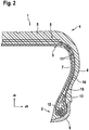
- Figure 2 shows the right side of a radial partial section through a further pneumatic vehicle tire 1.
- the carcass 3 has a so-called floating carcass ply 15 in addition to a carcass ply 11, which ends in an outer carcass flare 13 below the superstructure. This extends coherently between the electrically conductive bead 9 and the superstructure 4 as the axially outermost layer of the carcass 3 and ends in the respective areas.
- Its axially outer surface is covered with a pad 14 which contacts the superstructure 3 and the electrically conductive bead sole 14 and connects them in an electrically conductive manner.
- the pad 14 is a strip with a thickness of 1 mm and an average width of 10 mm. 6 such strips are arranged at equidistant intervals around the circumference of the tire.
- Figure 3 shows a radial partial section through a pneumatic vehicle tire 1 having a carcass 3 with a divided carcass ply, which extends from one tire bead 2 over the superstructure 4 to the other tire bead 2 and is divided into two carcass ply parts 16, 17 in the region of the superstructure 4 in the circumferential direction of the pneumatic vehicle tire 1 is.
- the two carcass ply parts 16, 17 overlap in the area of the superstructure 4.
- the carcass ply part 16 ends in the area of the superstructure 4 and contacts it at the end point 18 of the carcass ply part 16.
- the tire bead 2 of the pneumatic vehicle tire 1 adjoining the carcass ply part 16 has an electrically conductive bead 9
- the carcass ply part 16 has a support 14 which extends axially on the inside along the carcass ply part 16 from the region of the electrically conductive bead sole 9 to the end point 18 of the carcass ply part 16 or extends further and contacts both the superstructure 4 and the electrically conductive bead sole 9 and connects them in an electrically conductive manner.
- Figure 4 shows a further radial partial section through a pneumatic vehicle tire 1.
- the carcass 3 of the pneumatic vehicle tire has two carcass plies 11, one carcass ply 11 being a carcass ply divided into two carcass ply parts 16, 17.
- the carcass ply part 16 has a support 14 which connects the electrically conductive bead sole 9 to the superstructure 4 in an electrically conductive manner.
- a surface of the divided carcass ply is primarily applied, not the surface of the carcass.
Landscapes
- Engineering & Computer Science (AREA)
- Mechanical Engineering (AREA)
- Tires In General (AREA)
- Processing And Handling Of Plastics And Other Materials For Molding In General (AREA)
Applications Claiming Priority (2)
| Application Number | Priority Date | Filing Date | Title |
|---|---|---|---|
| DE102013104114.0A DE102013104114A1 (de) | 2013-04-24 | 2013-04-24 | Fahrzeugluftreifen und Verfahren zur Herstellung eines Fahrzeugluftreifens |
| PCT/EP2014/051987 WO2014173551A1 (de) | 2013-04-24 | 2014-02-03 | Fahrzeugluftreifen und verfahren zur herstellung eines fahrzeugluftreifens |
Publications (2)
| Publication Number | Publication Date |
|---|---|
| EP2988956A1 EP2988956A1 (de) | 2016-03-02 |
| EP2988956B1 true EP2988956B1 (de) | 2020-01-15 |
Family
ID=50070534
Family Applications (1)
| Application Number | Title | Priority Date | Filing Date |
|---|---|---|---|
| EP14703316.1A Active EP2988956B1 (de) | 2013-04-24 | 2014-02-03 | Fahrzeugluftreifen und verfahren zur herstellung eines fahrzeugluftreifens |
Country Status (5)
| Country | Link |
|---|---|
| US (1) | US10071604B2 (enExample) |
| EP (1) | EP2988956B1 (enExample) |
| JP (1) | JP2016515492A (enExample) |
| DE (1) | DE102013104114A1 (enExample) |
| WO (1) | WO2014173551A1 (enExample) |
Families Citing this family (7)
| Publication number | Priority date | Publication date | Assignee | Title |
|---|---|---|---|---|
| US20180178595A1 (en) | 2015-06-15 | 2018-06-28 | Bridgestone Americas Tire Operations, Llc | Tire having a conductivity path |
| WO2017086958A1 (en) * | 2015-11-18 | 2017-05-26 | Compagnie Generale Des Etablissements Michelin | Improved pneumatic tire with segmented body ply |
| DE102015223393A1 (de) | 2015-11-26 | 2017-06-01 | Continental Reifen Deutschland Gmbh | Fahrzeugluftreifen |
| EP3501847B1 (en) | 2017-12-22 | 2020-11-11 | Hankook Tire Co., Ltd. | Cord reinforced rubberlayer for a tire, method for manufacturing the same, and tire comprising the same |
| IT201800009290A1 (it) * | 2018-10-09 | 2020-04-09 | Bridgestone Europe Nv Sa | Pneumatico con bassa resistenza elettrica |
| JP7181158B2 (ja) * | 2019-06-21 | 2022-11-30 | 株式会社ブリヂストン | タイヤ |
| CN111361361A (zh) * | 2020-04-20 | 2020-07-03 | 江苏通用科技股份有限公司 | 防静电轮胎结构 |
Citations (1)
| Publication number | Priority date | Publication date | Assignee | Title |
|---|---|---|---|---|
| EP2933122A1 (en) * | 2013-01-09 | 2015-10-21 | Sumitomo Rubber Industries, Ltd. | Pneumatic tire |
Family Cites Families (14)
| Publication number | Priority date | Publication date | Assignee | Title |
|---|---|---|---|---|
| GB544757A (en) * | 1940-02-15 | 1942-04-27 | Us Rubber Co | Improvements in a pneumatic tyre and method of making same |
| FR2612130B1 (fr) * | 1987-03-12 | 1989-06-16 | Michelin & Cie | Enveloppe de pneumatique comportant des tringles constituees chacune par un empilement de rubans de forme coudee |
| IT1219241B (it) * | 1988-04-27 | 1990-05-03 | Firestone Int Dev Spa | Pneumatico radiale per veicoli |
| JP3018088B2 (ja) * | 1990-07-09 | 2000-03-13 | 横浜ゴム株式会社 | 空気入りタイヤ |
| DE69717958T2 (de) | 1996-10-17 | 2003-04-30 | Sumitomo Rubber Industries Ltd., Kobe | Luftreifen |
| US7011125B2 (en) * | 2003-11-18 | 2006-03-14 | The Goodyear Tire & Rubber Company | Tire with rubber sidewall containing internal electrically conductive rubber strip |
| EP1659005B1 (fr) * | 2004-11-18 | 2008-01-23 | Societe de Technologie Michelin | Gomme conductrice localisée |
| JP4910677B2 (ja) * | 2006-12-18 | 2012-04-04 | 横浜ゴム株式会社 | 空気入りタイヤ |
| JP2008308083A (ja) * | 2007-06-15 | 2008-12-25 | Sumitomo Rubber Ind Ltd | 空気入りタイヤ |
| JP2010018123A (ja) * | 2008-07-09 | 2010-01-28 | Yokohama Rubber Co Ltd:The | 空気入りタイヤ |
| JP5293290B2 (ja) * | 2009-03-11 | 2013-09-18 | 横浜ゴム株式会社 | 空気入りタイヤ |
| US20100277027A1 (en) | 2009-04-30 | 2010-11-04 | Gm Global Technology Operations, Inc. | Skew pattern for a permanent magnet rotor |
| DE102010017444A1 (de) | 2010-06-18 | 2011-12-22 | Continental Reifen Deutschland Gmbh | Fahrzeugluftreifen mit Luftabführungsfäden und Verfahren zur Herstellung einer elektrisch leitfähigen Beschichtung für die Luftabführungsfäden |
| JP5608587B2 (ja) * | 2011-03-03 | 2014-10-15 | 東洋ゴム工業株式会社 | 空気入りタイヤの製造方法及び空気入りタイヤ |
-
2013
- 2013-04-24 DE DE102013104114.0A patent/DE102013104114A1/de not_active Withdrawn
-
2014
- 2014-02-03 WO PCT/EP2014/051987 patent/WO2014173551A1/de not_active Ceased
- 2014-02-03 JP JP2016508049A patent/JP2016515492A/ja active Pending
- 2014-02-03 EP EP14703316.1A patent/EP2988956B1/de active Active
-
2015
- 2015-10-26 US US14/923,138 patent/US10071604B2/en active Active
Patent Citations (1)
| Publication number | Priority date | Publication date | Assignee | Title |
|---|---|---|---|---|
| EP2933122A1 (en) * | 2013-01-09 | 2015-10-21 | Sumitomo Rubber Industries, Ltd. | Pneumatic tire |
Also Published As
| Publication number | Publication date |
|---|---|
| EP2988956A1 (de) | 2016-03-02 |
| US10071604B2 (en) | 2018-09-11 |
| US20160039252A1 (en) | 2016-02-11 |
| JP2016515492A (ja) | 2016-05-30 |
| DE102013104114A1 (de) | 2014-10-30 |
| WO2014173551A1 (de) | 2014-10-30 |
Similar Documents
| Publication | Publication Date | Title |
|---|---|---|
| EP2988956B1 (de) | Fahrzeugluftreifen und verfahren zur herstellung eines fahrzeugluftreifens | |
| EP3380343B1 (de) | Fahrzeugluftreifen | |
| EP3019352B1 (de) | Fahrzeugluftreifen | |
| DE102011001877B4 (de) | Fahrzeugluftreifen | |
| EP3680114B1 (de) | Fahrzeugluftreifen | |
| EP2536576A1 (de) | Fahrzeugluftreifen | |
| EP3103661B1 (de) | Verfahren zur herstellung einer elektrisch leitfähigen passage in einem fahrzeugluftreifen | |
| EP2560828A1 (de) | Fahrzeugluftreifen | |
| DE1181575B (de) | Luftreifen fuer Fahrzeugraeder | |
| DE112006004257B4 (de) | Verfahren zum Herstellen eines Luftreifens und Luftreifen | |
| EP3181380B1 (de) | Fahrzeugluftreifen | |
| EP2848434B1 (de) | Fahrzeugluftreifen | |
| EP3238958A1 (de) | Nutzfahrzeugreifen | |
| EP3427978B1 (de) | Fahrzeugluftreifen | |
| EP3181379B1 (de) | Fahrzeugluftreifen | |
| EP3325286B1 (de) | Fahrzeugluftreifen | |
| EP2939855B1 (de) | Fahrzeugluftreifen aufweisend einen Streifen aus einer elektrisch leitfähigen Gummimischung | |
| DE102010037711B4 (de) | Verfahren zur Herstellung eines Fahrzeugluftreifens | |
| EP3181381B1 (de) | Fahrzeugluftreifen | |
| EP4015241B1 (de) | Vollreifen und verfahren zur herstellung | |
| DE102020209457A1 (de) | Fahrzeugluftreifen aufweisend einen elektrisch leitfähigen Pfad | |
| DE102013222318A1 (de) | Festigkeitsträgerlage für elastomere Erzeugnisse und Verfahren zur Herstellung einer Festigkeitsträgerlage | |
| EP2078622B1 (de) | Fahrzeugluftreifen | |
| DE102017211752A1 (de) | Fahrzeugluftreifen | |
| DE102023211510A1 (de) | Fahrzeugreifen |
Legal Events
| Date | Code | Title | Description |
|---|---|---|---|
| PUAI | Public reference made under article 153(3) epc to a published international application that has entered the european phase |
Free format text: ORIGINAL CODE: 0009012 |
|
| 17P | Request for examination filed |
Effective date: 20151124 |
|
| AK | Designated contracting states |
Kind code of ref document: A1 Designated state(s): AL AT BE BG CH CY CZ DE DK EE ES FI FR GB GR HR HU IE IS IT LI LT LU LV MC MK MT NL NO PL PT RO RS SE SI SK SM TR |
|
| AX | Request for extension of the european patent |
Extension state: BA ME |
|
| DAX | Request for extension of the european patent (deleted) | ||
| STAA | Information on the status of an ep patent application or granted ep patent |
Free format text: STATUS: EXAMINATION IS IN PROGRESS |
|
| 17Q | First examination report despatched |
Effective date: 20190117 |
|
| RIC1 | Information provided on ipc code assigned before grant |
Ipc: B29D 30/08 20060101ALI20190705BHEP Ipc: B60C 9/02 20060101ALI20190705BHEP Ipc: B60C 15/06 20060101ALI20190705BHEP Ipc: B60C 19/08 20060101AFI20190705BHEP Ipc: B60C 15/00 20060101ALI20190705BHEP |
|
| GRAP | Despatch of communication of intention to grant a patent |
Free format text: ORIGINAL CODE: EPIDOSNIGR1 |
|
| STAA | Information on the status of an ep patent application or granted ep patent |
Free format text: STATUS: GRANT OF PATENT IS INTENDED |
|
| INTG | Intention to grant announced |
Effective date: 20190916 |
|
| GRAS | Grant fee paid |
Free format text: ORIGINAL CODE: EPIDOSNIGR3 |
|
| GRAA | (expected) grant |
Free format text: ORIGINAL CODE: 0009210 |
|
| STAA | Information on the status of an ep patent application or granted ep patent |
Free format text: STATUS: THE PATENT HAS BEEN GRANTED |
|
| AK | Designated contracting states |
Kind code of ref document: B1 Designated state(s): AL AT BE BG CH CY CZ DE DK EE ES FI FR GB GR HR HU IE IS IT LI LT LU LV MC MK MT NL NO PL PT RO RS SE SI SK SM TR |
|
| REG | Reference to a national code |
Ref country code: CH Ref legal event code: EP Ref country code: GB Ref legal event code: FG4D Free format text: NOT ENGLISH |
|
| REG | Reference to a national code |
Ref country code: IE Ref legal event code: FG4D Free format text: LANGUAGE OF EP DOCUMENT: GERMAN |
|
| REG | Reference to a national code |
Ref country code: DE Ref legal event code: R096 Ref document number: 502014013470 Country of ref document: DE |
|
| REG | Reference to a national code |
Ref country code: AT Ref legal event code: REF Ref document number: 1224839 Country of ref document: AT Kind code of ref document: T Effective date: 20200215 |
|
| REG | Reference to a national code |
Ref country code: NL Ref legal event code: MP Effective date: 20200115 |
|
| REG | Reference to a national code |
Ref country code: LT Ref legal event code: MG4D |
|
| PG25 | Lapsed in a contracting state [announced via postgrant information from national office to epo] |
Ref country code: PT Free format text: LAPSE BECAUSE OF FAILURE TO SUBMIT A TRANSLATION OF THE DESCRIPTION OR TO PAY THE FEE WITHIN THE PRESCRIBED TIME-LIMIT Effective date: 20200607 Ref country code: NO Free format text: LAPSE BECAUSE OF FAILURE TO SUBMIT A TRANSLATION OF THE DESCRIPTION OR TO PAY THE FEE WITHIN THE PRESCRIBED TIME-LIMIT Effective date: 20200415 Ref country code: RS Free format text: LAPSE BECAUSE OF FAILURE TO SUBMIT A TRANSLATION OF THE DESCRIPTION OR TO PAY THE FEE WITHIN THE PRESCRIBED TIME-LIMIT Effective date: 20200115 Ref country code: FI Free format text: LAPSE BECAUSE OF FAILURE TO SUBMIT A TRANSLATION OF THE DESCRIPTION OR TO PAY THE FEE WITHIN THE PRESCRIBED TIME-LIMIT Effective date: 20200115 Ref country code: NL Free format text: LAPSE BECAUSE OF FAILURE TO SUBMIT A TRANSLATION OF THE DESCRIPTION OR TO PAY THE FEE WITHIN THE PRESCRIBED TIME-LIMIT Effective date: 20200115 |
|
| PG25 | Lapsed in a contracting state [announced via postgrant information from national office to epo] |
Ref country code: HR Free format text: LAPSE BECAUSE OF FAILURE TO SUBMIT A TRANSLATION OF THE DESCRIPTION OR TO PAY THE FEE WITHIN THE PRESCRIBED TIME-LIMIT Effective date: 20200115 Ref country code: BG Free format text: LAPSE BECAUSE OF FAILURE TO SUBMIT A TRANSLATION OF THE DESCRIPTION OR TO PAY THE FEE WITHIN THE PRESCRIBED TIME-LIMIT Effective date: 20200415 Ref country code: LV Free format text: LAPSE BECAUSE OF FAILURE TO SUBMIT A TRANSLATION OF THE DESCRIPTION OR TO PAY THE FEE WITHIN THE PRESCRIBED TIME-LIMIT Effective date: 20200115 Ref country code: SE Free format text: LAPSE BECAUSE OF FAILURE TO SUBMIT A TRANSLATION OF THE DESCRIPTION OR TO PAY THE FEE WITHIN THE PRESCRIBED TIME-LIMIT Effective date: 20200115 Ref country code: IS Free format text: LAPSE BECAUSE OF FAILURE TO SUBMIT A TRANSLATION OF THE DESCRIPTION OR TO PAY THE FEE WITHIN THE PRESCRIBED TIME-LIMIT Effective date: 20200515 Ref country code: GR Free format text: LAPSE BECAUSE OF FAILURE TO SUBMIT A TRANSLATION OF THE DESCRIPTION OR TO PAY THE FEE WITHIN THE PRESCRIBED TIME-LIMIT Effective date: 20200416 |
|
| REG | Reference to a national code |
Ref country code: CH Ref legal event code: PL |
|
| REG | Reference to a national code |
Ref country code: DE Ref legal event code: R097 Ref document number: 502014013470 Country of ref document: DE |
|
| REG | Reference to a national code |
Ref country code: BE Ref legal event code: MM Effective date: 20200229 |
|
| PG25 | Lapsed in a contracting state [announced via postgrant information from national office to epo] |
Ref country code: CZ Free format text: LAPSE BECAUSE OF FAILURE TO SUBMIT A TRANSLATION OF THE DESCRIPTION OR TO PAY THE FEE WITHIN THE PRESCRIBED TIME-LIMIT Effective date: 20200115 Ref country code: RO Free format text: LAPSE BECAUSE OF FAILURE TO SUBMIT A TRANSLATION OF THE DESCRIPTION OR TO PAY THE FEE WITHIN THE PRESCRIBED TIME-LIMIT Effective date: 20200115 Ref country code: SK Free format text: LAPSE BECAUSE OF FAILURE TO SUBMIT A TRANSLATION OF THE DESCRIPTION OR TO PAY THE FEE WITHIN THE PRESCRIBED TIME-LIMIT Effective date: 20200115 Ref country code: LU Free format text: LAPSE BECAUSE OF NON-PAYMENT OF DUE FEES Effective date: 20200203 Ref country code: MC Free format text: LAPSE BECAUSE OF FAILURE TO SUBMIT A TRANSLATION OF THE DESCRIPTION OR TO PAY THE FEE WITHIN THE PRESCRIBED TIME-LIMIT Effective date: 20200115 Ref country code: DK Free format text: LAPSE BECAUSE OF FAILURE TO SUBMIT A TRANSLATION OF THE DESCRIPTION OR TO PAY THE FEE WITHIN THE PRESCRIBED TIME-LIMIT Effective date: 20200115 Ref country code: EE Free format text: LAPSE BECAUSE OF FAILURE TO SUBMIT A TRANSLATION OF THE DESCRIPTION OR TO PAY THE FEE WITHIN THE PRESCRIBED TIME-LIMIT Effective date: 20200115 Ref country code: SM Free format text: LAPSE BECAUSE OF FAILURE TO SUBMIT A TRANSLATION OF THE DESCRIPTION OR TO PAY THE FEE WITHIN THE PRESCRIBED TIME-LIMIT Effective date: 20200115 Ref country code: ES Free format text: LAPSE BECAUSE OF FAILURE TO SUBMIT A TRANSLATION OF THE DESCRIPTION OR TO PAY THE FEE WITHIN THE PRESCRIBED TIME-LIMIT Effective date: 20200115 Ref country code: LT Free format text: LAPSE BECAUSE OF FAILURE TO SUBMIT A TRANSLATION OF THE DESCRIPTION OR TO PAY THE FEE WITHIN THE PRESCRIBED TIME-LIMIT Effective date: 20200115 |
|
| PLBE | No opposition filed within time limit |
Free format text: ORIGINAL CODE: 0009261 |
|
| STAA | Information on the status of an ep patent application or granted ep patent |
Free format text: STATUS: NO OPPOSITION FILED WITHIN TIME LIMIT |
|
| PG25 | Lapsed in a contracting state [announced via postgrant information from national office to epo] |
Ref country code: LI Free format text: LAPSE BECAUSE OF NON-PAYMENT OF DUE FEES Effective date: 20200229 Ref country code: CH Free format text: LAPSE BECAUSE OF NON-PAYMENT OF DUE FEES Effective date: 20200229 |
|
| 26N | No opposition filed |
Effective date: 20201016 |
|
| PG25 | Lapsed in a contracting state [announced via postgrant information from national office to epo] |
Ref country code: IE Free format text: LAPSE BECAUSE OF NON-PAYMENT OF DUE FEES Effective date: 20200203 Ref country code: IT Free format text: LAPSE BECAUSE OF FAILURE TO SUBMIT A TRANSLATION OF THE DESCRIPTION OR TO PAY THE FEE WITHIN THE PRESCRIBED TIME-LIMIT Effective date: 20200115 |
|
| PG25 | Lapsed in a contracting state [announced via postgrant information from national office to epo] |
Ref country code: PL Free format text: LAPSE BECAUSE OF FAILURE TO SUBMIT A TRANSLATION OF THE DESCRIPTION OR TO PAY THE FEE WITHIN THE PRESCRIBED TIME-LIMIT Effective date: 20200115 Ref country code: SI Free format text: LAPSE BECAUSE OF FAILURE TO SUBMIT A TRANSLATION OF THE DESCRIPTION OR TO PAY THE FEE WITHIN THE PRESCRIBED TIME-LIMIT Effective date: 20200115 Ref country code: BE Free format text: LAPSE BECAUSE OF NON-PAYMENT OF DUE FEES Effective date: 20200229 |
|
| GBPC | Gb: european patent ceased through non-payment of renewal fee |
Effective date: 20200415 |
|
| REG | Reference to a national code |
Ref country code: AT Ref legal event code: MM01 Ref document number: 1224839 Country of ref document: AT Kind code of ref document: T Effective date: 20200203 |
|
| PG25 | Lapsed in a contracting state [announced via postgrant information from national office to epo] |
Ref country code: GB Free format text: LAPSE BECAUSE OF NON-PAYMENT OF DUE FEES Effective date: 20200415 |
|
| PG25 | Lapsed in a contracting state [announced via postgrant information from national office to epo] |
Ref country code: AT Free format text: LAPSE BECAUSE OF NON-PAYMENT OF DUE FEES Effective date: 20200203 |
|
| PG25 | Lapsed in a contracting state [announced via postgrant information from national office to epo] |
Ref country code: TR Free format text: LAPSE BECAUSE OF FAILURE TO SUBMIT A TRANSLATION OF THE DESCRIPTION OR TO PAY THE FEE WITHIN THE PRESCRIBED TIME-LIMIT Effective date: 20200115 Ref country code: MT Free format text: LAPSE BECAUSE OF FAILURE TO SUBMIT A TRANSLATION OF THE DESCRIPTION OR TO PAY THE FEE WITHIN THE PRESCRIBED TIME-LIMIT Effective date: 20200115 Ref country code: CY Free format text: LAPSE BECAUSE OF FAILURE TO SUBMIT A TRANSLATION OF THE DESCRIPTION OR TO PAY THE FEE WITHIN THE PRESCRIBED TIME-LIMIT Effective date: 20200115 |
|
| PG25 | Lapsed in a contracting state [announced via postgrant information from national office to epo] |
Ref country code: MK Free format text: LAPSE BECAUSE OF FAILURE TO SUBMIT A TRANSLATION OF THE DESCRIPTION OR TO PAY THE FEE WITHIN THE PRESCRIBED TIME-LIMIT Effective date: 20200115 Ref country code: AL Free format text: LAPSE BECAUSE OF FAILURE TO SUBMIT A TRANSLATION OF THE DESCRIPTION OR TO PAY THE FEE WITHIN THE PRESCRIBED TIME-LIMIT Effective date: 20200115 |
|
| REG | Reference to a national code |
Ref country code: DE Ref legal event code: R081 Ref document number: 502014013470 Country of ref document: DE Owner name: CONTINENTAL REIFEN DEUTSCHLAND GMBH, DE Free format text: FORMER OWNER: CONTINENTAL REIFEN DEUTSCHLAND GMBH, 30165 HANNOVER, DE |
|
| PGFP | Annual fee paid to national office [announced via postgrant information from national office to epo] |
Ref country code: FR Payment date: 20240221 Year of fee payment: 11 |
|
| PGFP | Annual fee paid to national office [announced via postgrant information from national office to epo] |
Ref country code: DE Payment date: 20250228 Year of fee payment: 12 |