EP2988700B1 - Dispositif vasculaire implantable ayant des entretoises longitudinales - Google Patents
Dispositif vasculaire implantable ayant des entretoises longitudinales Download PDFInfo
- Publication number
- EP2988700B1 EP2988700B1 EP14797866.2A EP14797866A EP2988700B1 EP 2988700 B1 EP2988700 B1 EP 2988700B1 EP 14797866 A EP14797866 A EP 14797866A EP 2988700 B1 EP2988700 B1 EP 2988700B1
- Authority
- EP
- European Patent Office
- Prior art keywords
- frame
- struts
- connecting members
- longitudinal struts
- neighboring
- Prior art date
- Legal status (The legal status is an assumption and is not a legal conclusion. Google has not performed a legal analysis and makes no representation as to the accuracy of the status listed.)
- Active
Links
- 230000002792 vascular Effects 0.000 title description 3
- 108091008698 baroreceptors Proteins 0.000 claims description 26
- 210000001774 pressoreceptor Anatomy 0.000 claims description 26
- 210000001367 artery Anatomy 0.000 claims description 23
- 230000036772 blood pressure Effects 0.000 claims description 23
- 230000008859 change Effects 0.000 claims description 20
- 230000004044 response Effects 0.000 claims description 10
- 230000007423 decrease Effects 0.000 claims description 8
- 230000000638 stimulation Effects 0.000 claims description 8
- 238000000926 separation method Methods 0.000 claims description 6
- 230000003247 decreasing effect Effects 0.000 claims description 5
- 210000003038 endothelium Anatomy 0.000 claims description 5
- 239000008280 blood Substances 0.000 claims description 2
- 210000004369 blood Anatomy 0.000 claims description 2
- 230000007704 transition Effects 0.000 claims 1
- 238000012360 testing method Methods 0.000 description 19
- 210000000412 mechanoreceptor Anatomy 0.000 description 15
- 238000000034 method Methods 0.000 description 15
- 108091008709 muscle spindles Proteins 0.000 description 15
- 210000004204 blood vessel Anatomy 0.000 description 13
- 230000003205 diastolic effect Effects 0.000 description 12
- 210000001715 carotid artery Anatomy 0.000 description 11
- 210000001326 carotid sinus Anatomy 0.000 description 11
- 206010020772 Hypertension Diseases 0.000 description 8
- 230000002708 enhancing effect Effects 0.000 description 7
- 229910052751 metal Inorganic materials 0.000 description 7
- 239000002184 metal Substances 0.000 description 7
- 230000000541 pulsatile effect Effects 0.000 description 5
- 210000002376 aorta thoracic Anatomy 0.000 description 4
- 210000003169 central nervous system Anatomy 0.000 description 4
- 210000005036 nerve Anatomy 0.000 description 4
- 238000007493 shaping process Methods 0.000 description 4
- 230000011664 signaling Effects 0.000 description 4
- 210000005166 vasculature Anatomy 0.000 description 4
- 230000003321 amplification Effects 0.000 description 3
- 210000004004 carotid artery internal Anatomy 0.000 description 3
- 210000004027 cell Anatomy 0.000 description 3
- 238000006243 chemical reaction Methods 0.000 description 3
- 238000006073 displacement reaction Methods 0.000 description 3
- 239000007943 implant Substances 0.000 description 3
- 238000003199 nucleic acid amplification method Methods 0.000 description 3
- 108020003175 receptors Proteins 0.000 description 3
- 230000009471 action Effects 0.000 description 2
- 230000036982 action potential Effects 0.000 description 2
- 210000003484 anatomy Anatomy 0.000 description 2
- 230000008901 benefit Effects 0.000 description 2
- 210000001168 carotid artery common Anatomy 0.000 description 2
- 235000005911 diet Nutrition 0.000 description 2
- 230000037213 diet Effects 0.000 description 2
- 230000000694 effects Effects 0.000 description 2
- 210000001932 glossopharyngeal nerve Anatomy 0.000 description 2
- 230000012010 growth Effects 0.000 description 2
- 239000000463 material Substances 0.000 description 2
- 229910001000 nickel titanium Inorganic materials 0.000 description 2
- 230000002093 peripheral effect Effects 0.000 description 2
- 239000005020 polyethylene terephthalate Substances 0.000 description 2
- 229920000139 polyethylene terephthalate Polymers 0.000 description 2
- 230000004936 stimulating effect Effects 0.000 description 2
- 206010007559 Cardiac failure congestive Diseases 0.000 description 1
- 206010019280 Heart failures Diseases 0.000 description 1
- 239000005041 Mylar™ Substances 0.000 description 1
- 208000008589 Obesity Diseases 0.000 description 1
- 208000001647 Renal Insufficiency Diseases 0.000 description 1
- 229910045601 alloy Inorganic materials 0.000 description 1
- 239000000956 alloy Substances 0.000 description 1
- 230000009118 appropriate response Effects 0.000 description 1
- 239000000560 biocompatible material Substances 0.000 description 1
- 230000017531 blood circulation Effects 0.000 description 1
- 210000000269 carotid artery external Anatomy 0.000 description 1
- 230000010261 cell growth Effects 0.000 description 1
- 230000001419 dependent effect Effects 0.000 description 1
- 238000013461 design Methods 0.000 description 1
- 230000001627 detrimental effect Effects 0.000 description 1
- 210000002889 endothelial cell Anatomy 0.000 description 1
- 230000003511 endothelial effect Effects 0.000 description 1
- 239000010408 film Substances 0.000 description 1
- 230000004217 heart function Effects 0.000 description 1
- 206010020718 hyperplasia Diseases 0.000 description 1
- 238000000338 in vitro Methods 0.000 description 1
- 238000010348 incorporation Methods 0.000 description 1
- 230000002401 inhibitory effect Effects 0.000 description 1
- 201000006370 kidney failure Diseases 0.000 description 1
- 230000003907 kidney function Effects 0.000 description 1
- 230000000670 limiting effect Effects 0.000 description 1
- 238000004519 manufacturing process Methods 0.000 description 1
- 230000010534 mechanism of action Effects 0.000 description 1
- 238000012986 modification Methods 0.000 description 1
- 230000004048 modification Effects 0.000 description 1
- HLXZNVUGXRDIFK-UHFFFAOYSA-N nickel titanium Chemical compound [Ti].[Ti].[Ti].[Ti].[Ti].[Ti].[Ti].[Ti].[Ti].[Ti].[Ti].[Ni].[Ni].[Ni].[Ni].[Ni].[Ni].[Ni].[Ni].[Ni].[Ni].[Ni].[Ni].[Ni].[Ni] HLXZNVUGXRDIFK-UHFFFAOYSA-N 0.000 description 1
- 235000020824 obesity Nutrition 0.000 description 1
- -1 polyethylene terephthalate Polymers 0.000 description 1
- 230000010349 pulsation Effects 0.000 description 1
- 230000009467 reduction Effects 0.000 description 1
- 230000002829 reductive effect Effects 0.000 description 1
- 230000029865 regulation of blood pressure Effects 0.000 description 1
- 210000002254 renal artery Anatomy 0.000 description 1
- 238000011160 research Methods 0.000 description 1
- 230000008268 response to external stimulus Effects 0.000 description 1
- 230000003938 response to stress Effects 0.000 description 1
- 230000035945 sensitivity Effects 0.000 description 1
- 238000006467 substitution reaction Methods 0.000 description 1
- 230000035488 systolic blood pressure Effects 0.000 description 1
- 239000010409 thin film Substances 0.000 description 1
- 210000001519 tissue Anatomy 0.000 description 1
- 230000003966 vascular damage Effects 0.000 description 1
Images


Classifications
-
- A—HUMAN NECESSITIES
- A61—MEDICAL OR VETERINARY SCIENCE; HYGIENE
- A61F—FILTERS IMPLANTABLE INTO BLOOD VESSELS; PROSTHESES; DEVICES PROVIDING PATENCY TO, OR PREVENTING COLLAPSING OF, TUBULAR STRUCTURES OF THE BODY, e.g. STENTS; ORTHOPAEDIC, NURSING OR CONTRACEPTIVE DEVICES; FOMENTATION; TREATMENT OR PROTECTION OF EYES OR EARS; BANDAGES, DRESSINGS OR ABSORBENT PADS; FIRST-AID KITS
- A61F2/00—Filters implantable into blood vessels; Prostheses, i.e. artificial substitutes or replacements for parts of the body; Appliances for connecting them with the body; Devices providing patency to, or preventing collapsing of, tubular structures of the body, e.g. stents
- A61F2/82—Devices providing patency to, or preventing collapsing of, tubular structures of the body, e.g. stents
- A61F2/844—Devices providing patency to, or preventing collapsing of, tubular structures of the body, e.g. stents folded prior to deployment
-
- A—HUMAN NECESSITIES
- A61—MEDICAL OR VETERINARY SCIENCE; HYGIENE
- A61F—FILTERS IMPLANTABLE INTO BLOOD VESSELS; PROSTHESES; DEVICES PROVIDING PATENCY TO, OR PREVENTING COLLAPSING OF, TUBULAR STRUCTURES OF THE BODY, e.g. STENTS; ORTHOPAEDIC, NURSING OR CONTRACEPTIVE DEVICES; FOMENTATION; TREATMENT OR PROTECTION OF EYES OR EARS; BANDAGES, DRESSINGS OR ABSORBENT PADS; FIRST-AID KITS
- A61F2/00—Filters implantable into blood vessels; Prostheses, i.e. artificial substitutes or replacements for parts of the body; Appliances for connecting them with the body; Devices providing patency to, or preventing collapsing of, tubular structures of the body, e.g. stents
- A61F2/82—Devices providing patency to, or preventing collapsing of, tubular structures of the body, e.g. stents
- A61F2/86—Stents in a form characterised by the wire-like elements; Stents in the form characterised by a net-like or mesh-like structure
- A61F2/90—Stents in a form characterised by the wire-like elements; Stents in the form characterised by a net-like or mesh-like structure characterised by a net-like or mesh-like structure
- A61F2/91—Stents in a form characterised by the wire-like elements; Stents in the form characterised by a net-like or mesh-like structure characterised by a net-like or mesh-like structure made from perforated sheet material or tubes, e.g. perforated by laser cuts or etched holes
- A61F2/915—Stents in a form characterised by the wire-like elements; Stents in the form characterised by a net-like or mesh-like structure characterised by a net-like or mesh-like structure made from perforated sheet material or tubes, e.g. perforated by laser cuts or etched holes with bands having a meander structure, adjacent bands being connected to each other
- A61F2002/9155—Adjacent bands being connected to each other
- A61F2002/91558—Adjacent bands being connected to each other connected peak to peak
-
- A—HUMAN NECESSITIES
- A61—MEDICAL OR VETERINARY SCIENCE; HYGIENE
- A61F—FILTERS IMPLANTABLE INTO BLOOD VESSELS; PROSTHESES; DEVICES PROVIDING PATENCY TO, OR PREVENTING COLLAPSING OF, TUBULAR STRUCTURES OF THE BODY, e.g. STENTS; ORTHOPAEDIC, NURSING OR CONTRACEPTIVE DEVICES; FOMENTATION; TREATMENT OR PROTECTION OF EYES OR EARS; BANDAGES, DRESSINGS OR ABSORBENT PADS; FIRST-AID KITS
- A61F2230/00—Geometry of prostheses classified in groups A61F2/00 - A61F2/26 or A61F2/82 or A61F9/00 or A61F11/00 or subgroups thereof
- A61F2230/0002—Two-dimensional shapes, e.g. cross-sections
- A61F2230/0017—Angular shapes
- A61F2230/0019—Angular shapes rectangular
-
- A—HUMAN NECESSITIES
- A61—MEDICAL OR VETERINARY SCIENCE; HYGIENE
- A61F—FILTERS IMPLANTABLE INTO BLOOD VESSELS; PROSTHESES; DEVICES PROVIDING PATENCY TO, OR PREVENTING COLLAPSING OF, TUBULAR STRUCTURES OF THE BODY, e.g. STENTS; ORTHOPAEDIC, NURSING OR CONTRACEPTIVE DEVICES; FOMENTATION; TREATMENT OR PROTECTION OF EYES OR EARS; BANDAGES, DRESSINGS OR ABSORBENT PADS; FIRST-AID KITS
- A61F2230/00—Geometry of prostheses classified in groups A61F2/00 - A61F2/26 or A61F2/82 or A61F9/00 or A61F11/00 or subgroups thereof
- A61F2230/0002—Two-dimensional shapes, e.g. cross-sections
- A61F2230/0017—Angular shapes
- A61F2230/0021—Angular shapes square
-
- A—HUMAN NECESSITIES
- A61—MEDICAL OR VETERINARY SCIENCE; HYGIENE
- A61F—FILTERS IMPLANTABLE INTO BLOOD VESSELS; PROSTHESES; DEVICES PROVIDING PATENCY TO, OR PREVENTING COLLAPSING OF, TUBULAR STRUCTURES OF THE BODY, e.g. STENTS; ORTHOPAEDIC, NURSING OR CONTRACEPTIVE DEVICES; FOMENTATION; TREATMENT OR PROTECTION OF EYES OR EARS; BANDAGES, DRESSINGS OR ABSORBENT PADS; FIRST-AID KITS
- A61F2240/00—Manufacturing or designing of prostheses classified in groups A61F2/00 - A61F2/26 or A61F2/82 or A61F9/00 or A61F11/00 or subgroups thereof
- A61F2240/001—Designing or manufacturing processes
- A61F2240/008—Means for testing implantable prostheses
-
- A—HUMAN NECESSITIES
- A61—MEDICAL OR VETERINARY SCIENCE; HYGIENE
- A61F—FILTERS IMPLANTABLE INTO BLOOD VESSELS; PROSTHESES; DEVICES PROVIDING PATENCY TO, OR PREVENTING COLLAPSING OF, TUBULAR STRUCTURES OF THE BODY, e.g. STENTS; ORTHOPAEDIC, NURSING OR CONTRACEPTIVE DEVICES; FOMENTATION; TREATMENT OR PROTECTION OF EYES OR EARS; BANDAGES, DRESSINGS OR ABSORBENT PADS; FIRST-AID KITS
- A61F2250/00—Special features of prostheses classified in groups A61F2/00 - A61F2/26 or A61F2/82 or A61F9/00 or A61F11/00 or subgroups thereof
- A61F2250/0058—Additional features; Implant or prostheses properties not otherwise provided for
- A61F2250/0096—Markers and sensors for detecting a position or changes of a position of an implant, e.g. RF sensors, ultrasound markers
- A61F2250/0098—Markers and sensors for detecting a position or changes of a position of an implant, e.g. RF sensors, ultrasound markers radio-opaque, e.g. radio-opaque markers
Definitions
- the present invention relates generally to a medical apparatus. More particularly, the present invention relates to an apparatus for shaping a portion of a blood vessel wall to enhance the response of a stretch receptor in a region of the wall.
- Hypertension is a medical condition characterized by elevated blood pressure and can result from a number of underlying factors, including genetics, obesity, diet, and the like. When diagnosed, hypertension is most commonly treated by changes in diet, exercise, and pharmaceutical intervention. More recently, it has been proposed to treat hypertension and related conditions by stimulating or modulating certain receptors in the patient's vasculature, which may be referred to as stretch receptors, strain receptors or baroreceptors. Stretch receptors are located in the walls of blood vessels such as the carotid arteries and the aortic arch, and the like. It has been found that stimulating the baroreceptors and/or the nerves connected to the baroreceptors, can reduce a patient's blood pressure.
- Baroreceptor nerves are stretch sensors surrounding the internal carotid artery, the aortic arch and other vasculature. An increase in blood pressure stretches the carotid sinus causing the baroreceptors to increase their basal rate of action generation. Action potentials are then conducted by the glossopharyngeal nerve to the central nervous system. This signaling modulates blood pressure. Research has suggested that stimulation of the baroreceptors in the vessel wall is helpful. If the pulsatile signal is lost, the baroreceptors reset and may no longer accurately sense blood pressure.
- US 2007/0038291 A1 discloses instrumentally-implantable frames comprising a plurality of hoops and longitudinal connections to form a tubular frame.
- US 2011/0178416 A1 discloses devices and methods for control of blood pressure.
- Preferred embodiments of the invention are described in the dependent claims appended hereto.
- an implantable frame comprises a plurality of corner structures configured to decrease pressure to the vessel wall and define pulsatility enhancing windows of the implantable frame.
- the corner structures may comprise plurality of neighboring longitudinal struts that extend in a longitudinal direction of the blood vessel when placed to form the vessel wall to a substantially polygonal cross-section and distribute pressure loading of the corner structure among the plurality of neighboring longitudinal struts to improve biocompatibility.
- the corner structures also allow increased forming of the vessel wall and can provide increased force and shaping of the vessel wall to enhance pulsatility of the vessel wall.
- each of the corner structures comprise a plurality of openings defined with the neighboring longitudinal struts and a thickness dimensioned to promote growth of an endothelium of the blood vessel over the corner structures in order to enhance biocompatibility.
- the corner structures can be connected with a plurality of connecting members that retain the corner structures in a spaced apart arrangement to form the vessel wall and define a plurality of windows that enhance pulsatility of the vessel wall in order to lower blood pressure of the patient.
- the plurality of windows can be arranged rotationally around a longitudinal axis of the frame and may comprise from about three to about five windows.
- the corner structures define a maximum transverse dimension across the frame and the corner structures receive a greater amount of force from the vessel wall than the connecting members when placed in the blood vessel in order to enhance pulsatility and lower blood pressure.
- the implantable device as described herein can be used to treat hypertension, and the treatment of hypertension can improve heart function and renal function of the patient, for example.
- the implantable device may delay or even avoid the onset of congestive heart failure and renal failure, for example.
- the stimulated receptors may comprise stress or stretch receptors generally, and reference is made to baroreceptors by way of example in accordance with examples.
- the implantable frame comprises a plurality a corner structures and connecting members coupled to the corner structures that define a plurality of pulsatility enhancing windows of the implantable device.
- the corner structures comprise a plurality of neighboring longitudinal struts.
- Each of the plurality of neighboring longitudinal struts may comprise two or more neighboring longitudinal struts.
- the plurality of neighboring longitudinal struts provides a more uniform electro-polish, and distributes force against the wall of vessel in order to increase amplification of pulsatility of the vessel wall.
- the plurality of neighboring longitudinal struts of each corner structure can provide increased force and distribute the load on the vessel wall over an area while providing endothelial cell growth of the vessel wall over the implantable frame.
- the implantable frame provides a metal to artery ratio of no more than about 12%, for example no more than about 10.5% or no more than about 10%, when the frame is placed in an artery having a diameter of about 5 mm, for example.
- the metal to artery ratio may comprise a percentage of the surface area of the frame contacting the vessel wall divided by the surface area of the vessel wall that covers the windows and frame when placed.
- the surface area of the vessel wall that covers the frame can be determined by a longitudinal length of the frame and the surface area of the artery wall along the longitudinal length of the frame.
- the metal to artery ratio can depend on the size of the artery.
- the implantable frame comprises corner structures having substantially straight struts oriented along the implant frame longitudinal axis and blood vessel longitudinal axis when placed.
- the straight length may comprise a substantial percentage of the implant frames overall length, for example greater than 30% in implants freely expanded unloaded configuration.
- this straight strut may have a substantial span between intersections with the connecting members forming a relatively long unsupported length, for example greater than 30% of the overall length of the device, in its freely expanded unloaded configuration.
- the corner structures that increase the contact surface area allow the creation of large pulsatility enhancing windows, for example, with structures that reduce the contact pressure against the vascular wall. These structures distribute the loads to prevent vascular damage and allow endothielization. These structures may include the "doubling-up" of neighboring longitudinal struts connected with transverse members so that two or more neighboring struts may take the place of a single strut in the corner structure.
- the pulsatility enhancing windows are sized to inhibit endothelial hyperplasia near the central portion of the window away from the corner structures and connecting members, for example, in order to promote pulsatility of the vessel wall.
- the pulsatility enhancing windows as described herein may comprise cells in accordance with some examples, the pulsatility enhancing windows as described herein differ substantially from the cells of prior stents, as the cells of prior stents inhibit pulsatility of the vessel wall.
- the implantable frame may have a plurality of peripheral windows arranged in a row around the periphery of the frame about the longitudinal axis. In many examples a single peripheral row of windows is provided around the periphery of the device about the longitudinal axis.
- a window comprises an opening between corner structures, and the window is defined with two corner structures and the two corresponding connecting members that connect and support the corner structures.
- Each window spans the majority of the overall longitudinal length of the frame, for example the window length can be at least about 60% of overall length of expanded frame.
- Examples provide a frame with a low metal to artery ratio of the contact surface profile that engages the arterial wall, for example no more than 10% and an appropriate number of pulsatile windows in order to provide enhanced pulsatility.
- the frame comprises 3, 4 or 5 windows to provide enhanced pulsatility.
- Work in relation to examples suggests that as the number of pulsatile windows increases, the area of the vessel wall shaped with the windows decreases.
- the windows can be arranged in a side by side configuration in order to form the pulsatility enhancing windows inside the lumen.
- the cross-sectional shape of the vessel wall may be determined by the number of windows.
- a frame having a single window may form a plane, and a frame having two windows may form a rectangular cross-section with a high aspect ratio, and a frame with 3 windows a triangle, 4 windows a quadrilateral, 5 windows a pentagon, and 6 windows a hexagon, for example.
- a single window may create two large flat sections of the arterial wall, while 3 windows would can create 3 flat sections of the arterial, wall, for example.
- the windows provide large flattened areas with of the vessel wall with a substantially reduced radius of curvature while inhibiting effects on blood flow and decreasing exposure of the frame to the vasculature, for example by providing growth of the endothelium over the implantable frame.
- Figures 1 and 2 show a blood vessel suitable for incorporation in accordance with examples.
- Figures 1 and 2 are external and cross-sectional views, respectively, of the blood vessel.
- the blood vessel may comprise an artery for example.
- the vessel may comprise an artery such as the carotid artery or the aortic arch.
- the carotid artery comprises a carotid sinus CAS.
- the carotid artery comprises a common carotid artery CCA and the bifurcation CAB, where the common carotid artery CCA bifurcates into the internal carotid artery ICA and the external carotid artery ECA.
- the carotid sinus CAS comprises baroreceptors also referred to herein as stretch receptors SR.
- the stretch receptors SR are located in the vascular wall VW.
- the carotid sinus comprises many stretch receptors, that may be located distal to the bifurcation CAB.
- the stretch receptors may be unevenly distributed around the circumference of the blood vessel for a given longitudinal location along the axis of the artery, for example.
- the patient anatomy may comprise a superior direction S, an inferior direction I, a medial direction M, and a lateral direction L, as will be understood by a person of ordinary skill in the art.
- Stimulation of the stretch sensors or baroreceptors within the internal carotid sinus results in a drop of blood pressure.
- Baroreceptor nerves are stretch sensors surrounding the internal carotid artery. An increase in blood pressure stretches the carotid sinus causing the baroreceptors to increase their basal rate of action generation. Action potentials are then conducted by the glossopharyngeal nerve to the central nervous system. This signaling modulates blood pressure. In order for the baroreceptor nerves to control blood pressure, vessel pulsatility is helpful. If the pulsatile signal is lost, the baroreceptors may reset and no longer accurately sense blood pressure.
- Examples are configured to maintain pulsatility of the vessel wall and to amplify the signal seen by the baroreceptors.
- the implantable frame By reshaping the artery to provide a cross-section having three or more substantially flattened sides, the implantable frame increases the rate of change and amplitude of the vessel wall movement. This leads to higher and more frequent afferent signaling from the baroreceptors to the central nervous system that lower blood pressure of the patient.
- a circular vessel allows the strain/displacement to be uniformly distributed around the circumference of the carotid sinus.
- the displacement of the vessel wall in the flattened portions over these windows is amplified with concomitant pulsatile flow.
- four windows defined with four corner structures and eight connecting members may provide a vessel wall having four sides and a rectangular cross-section. This amplification leads to a larger peak-to-peak difference in strain/displacement as compared to the strain experienced by the uniform diameter change with a circularly-shaped vessel.
- In vitro testing of the current example demonstrates the ability of the device to increase the peak-to-peak amplitude of movement by more than 2x in a mock vessel when compared to a non-implanted section of the same vessel.
- the carotid artery expands and comprises an expanded configuration as shown by the dash line.
- the carotid artery comprises a decreased size as shown by the solid line.
- the change in size stretches the vessel wall and stimulates the stretch receptors.
- the stimulated stretch receptors combined with the methods and apparatus as described herein may comprise stretch receptors at other locations of the vasculature such as the aortic arch, renal arteries, subclavien artery, braciocephalic artery, , and the like
- the examples as described herein can provide an amplification of the baroreceptor response curve so as to lower the patient's blood pressure and allow the patient to increase or decrease blood pressure in response to environmental stimulus such as exercise, as appropriate.
- the examples as described herein can provide an improved sensitivity of the baroreceptor response curve, such that the patient can have lowered blood pressure and while retaining a natural response to stress and provide appropriate response to increased activity and decreased activity
- FIG. 3A shows an implantable frame 100 in an expanded configuration for deployment, in accordance with examples.
- the expandable frame 100 is configured to form the arterial wall to enhance pulsatility of the vessel wall and decrease blood pressure.
- the expandable frame 100 comprises a longitudinal axis 103 that is substantially aligned with a longitudinal axis of the artery when placed.
- the expandable frame 100 defines an opening 107 through which blood can flow and pulsate the arterial wall.
- the expandable frame 100 comprises a plurality of windows 150 shaped to allow the vessel wall to pulsate.
- the plurality of windows may comprise a first window 152, a second window 154, a third window 156, and a fourth window 158.
- Each of the windows is shaped to form the vessel wall to increase deflection of the vessel wall.
- the expandable frame 100 comprises a plurality of corner structures 105, a first plurality of connecting members 120 on a first end and a second plurality of connecting members 130 on a second end.
- the plurality of corner structures 105 may comprise a first corner structure 105A, a second corner structure 105B, a third corner structure 105C and a fourth corner structure 105D, for example when the vessel wall cross-section is formed to a substantially a quadrilateral cross-section.
- Each of the plurality of corner structures 105 comprises a plurality of neighboring struts 110.
- the plurality of neighboring struts may comprise a first plurality of neighboring struts 110A, a second plurality of neighboring struts 110B, a third plurality of neighboring struts 110C, and a fourth plurality of neighboring struts 110D, for example.
- Each of the plurality of corner structures may have a corresponding plurality of neighboring struts, for example first corner structure 105A, second corner structure 105B, third corner structure 105C and fourth corner structure 105D may individually correspond to first plurality of neighboring struts 110A, second plurality of neighboring struts 110B, third plurality of neighboring struts 110C and fourth plurality of neighboring struts 110D, respectively.
- the plurality of neighboring struts of each of the corner structures 105 and the connecting members 120 and connecting members 130 define a plurality of windows 150.
- Each of the plurality of windows 150 is shaped to form the tissue to increase pulsatility of the vessel wall.
- the vessel wall is shaped to a substantially polygonal cross-section in order to enhance pulsatility of the vessel wall.
- each corner structure 105 is configured to distribute pressure to the vessel wall and allow the endothelium of the vessel wall to grow over the corner structure 105 in order to increase biocompatibility.
- each corner structure 105 comprises the plurality of neighboring struts 110 joined with connecting members that define openings of the corner structure that allow endothelium of the vessel wall to grow over the corner structure.
- the corner structure 105 comprises a first strut 112 and a second strut 114.
- the first strut 112 and the second strut 114 are joined with a plurality of transverse members comprising first transverse member 113, second transverse member 115, and third transverse member 117, for example.
- the plurality of struts and transverse members define a first opening 116 comprising a first slot and a second opening 118 comprising a second slot.
- the first plurality of connecting members 120 and the second plurality of connecting members 130 can be configured in one or more of many ways.
- Each of the first plurality of connecting members 120 may comprise a first extension 122, a second extension 124 and an intermediate portion 121.
- the first extension 122 extends to first strut 112.
- the second extension 124 extends to second strut 114.
- Each of the second plurality of connecting members 130 may comprise a first extension 132, a second extension 134 and an intermediate portion 131.
- the first extension 132 extends to first strut 112.
- the second extension 134 extends to second strut 114.
- each of the plurality of connecting members is expanded while the corner structures comprising the plurality of longitudinal struts and connecting members remain in a substantially fixed arrangement.
- the first extension and the second extension of each of the connecting members can be urged apart so as to define the plurality of windows while the plurality of neighboring longitudinal struts and connecting members remain substantially undeflected.
- the transverse members may deflect when the connecting members expand.
- the plurality of windows 150 extend around an outer boundary of the frame 100 in order to shape the vessel wall and define the substantially polygonal cross-section with the plurality of corner structures 105.
- the substantially polygonal cross section may comprise a triangular cross-section, a quadrilateral cross-section, or a pentagonal cross-section, for example.
- the wall of the blood vessel shaped with the connecting members will be shaped so as to deflect inwardly and outwardly when the connecting members and struts are fixed to the vessel wall, such that the substantially polygonal cross-section may comprise convex and concave portions extending between the corner structures when engaged with the frame, for example.
- each of the plurality of windows 150 can be defined with the plurality of corner structures 105 and the first plurality of connecting members 120 on a first end of frame 100 and a second plurality of connecting members 130 on a second end of frame 130 opposite the first end.
- Each of the plurality of struts can be configured in one or more of many ways to distribute the pressure of the corner structure comprising the plurality of struts.
- Each of the plurality of neighboring struts 110 may comprise from about two to about five neighboring struts for each corner structure 105, for example.
- Each of the plurality of longitudinal struts can be connected with a two or more transverse members, for example three or more transverse members.
- the number of openings defined with each of plurality of struts can be within a range from about 1 to 100 for example.
- FIG. 3B shows an end view of the implantable frame 100 of Figure 3A in the expanded configuration, in accordance with examples.
- the corner structures 105 are joined with the plurality of connecting members 120 on the first end and with the second plurality of connecting members on the second end.
- Each of the corner structures 105 is oriented with respect to the connecting members so as to define a plurality of angles 170 of the connecting members.
- the plurality of angles comprises a first angle 172, a second angle 174, a third angle 176 and a fourth angle 178, defined with first plurality of neighboring struts 105A, second plurality of neighboring struts 105B, third plurality of neighboring struts 105C, and fourth plurality of neighboring struts 105D, respectively.
- the angles can be similar or different, and may correspond to angles of a triangle, a quadrilateral, or a pentagon, for example.
- Figure 3C shows a flat pattern view of the implantable frame of Figures 3A and 3B , in accordance with examples.
- the implantable frame can be rolled to a form a narrow profile configuration of the frame 100 for delivery to a target site such as the carotid artery.
- the first plurality of connecting members 120 comprises a first connecting member 142, a second connecting member 144, a third connecting member 146 and a fourth connecting member 148.
- the second plurality of connecting members 130 comprises a first connecting member 162, a second connecting member 164, a third connecting member 166 and a fourth connecting member 168.
- the implantable frame When placed the target site such as the carotid sinus, the implantable frame can expand from the narrow profile configuration to the wide profile configuration with expansion of the connecting members such as first connecting members 120 and second connecting members 130 as described herein.
- the transverse members connect to the neighboring longitudinal struts on the ends of the struts between the struts and the connecting members in order to inhibit separation and deflection of the neighboring longitudinal struts.
- the transverse members can be located on the ends of the neighboring longitudinal struts between the struts and connecting members.
- transverse member 113 and transverse member 117 are located on the ends of neighboring struts 112 and 114 to inhibit separation of the second plurality of struts 110B.
- the other pluralities of neighboring longitudinal struts can be similarly connected to the transverse members as described herein.
- Additional structures can be provided on the implantable frame, such as radio opaque markers and openings for handling the frame with a tool, and these structures can be provided on the connecting members, for example.
- Figure 4 shows a pattern view of an implantable frame comprising a plurality of openings and struts, in which a plurality of substantially parallel slots extend between each of the plurality of neighboring struts, in accordance with examples.
- Each of the plurality of neighboring longitudinal struts 110 comprises first longitudinal strut 112, second longitudinal strut 114 and a third longitudinal strut 119.
- the third longitudinal strut 119 is located between the first longitudinal strut 112 and the second longitudinal strut 114 to define a plurality of openings comprising first slot 116 and second slot 118.
- the plurality of transverse members comprises first transverse member 113 and second transverse member 115 located on opposite ends of the struts in order to define the ends of the slots.
- the plurality of transverse members may extend to the ends of the plurality of neighboring longitudinal struts to define the ends of the slots.
- the transverse members connect to the neighboring longitudinal struts on the ends of the struts in order to inhibit separation and deflection of the neighboring longitudinal struts.
- the transverse members can be located on the ends of the neighboring longitudinal struts between the longitudinal struts and connecting members.
- transverse member 113 and transverse member 115 are located on the ends of neighboring struts 112, 114 and 119 to inhibit separation of the second plurality of struts 110B.
- the other pluralities of neighboring longitudinal struts can be similarly connected to the transverse members as described herein.
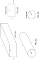
- Figure 5A illustrates a formed ("shaped") vessel wall during diastole, in accordance with examples.
- the shaped vessel wall may comprise a block shaped geometry, for example.
- Figure 5B illustrates a cross-section of the formed vessel wall of Figure 5A .
- the vessel wall may comprise four sides so as to define a rectangular shape, for example.
- the dimensions of the cross-section may comprise a first dimension A and a second dimension B of a quadrilateral for example.
- the first dimension A and the second dimension B can be different so as to define a rectangular cross-section.
- the first dimension A and the second dimension B can be substantially the same so as to define a square cross-section.
- the polygonal cross-section of the shaped vessel wall may comprise a number of sides within a range from about two to six, for example within a range from three to five sides.
- FIG. 5C illustrates a normal vessel wall during diastole, in accordance with examples.
- the vessel wall may comprise a cylindrical geometry for example, approximating the shape of the sinus of the carotid artery, for example.
- the changes can be expressed as a percentage (%)
- Figure 5D illustrates a cross-section of the normal vessel wall of Figure 5C .
- FIG. 6A shows normal vessel shape change between a diastolic configuration and a systolic configuration, in accordance with examples.
- the vessel wall comprises a diastolic diameter C and a systolic diameter D.
- the normal vessel change (Delta) can be defined as:
- % Delta D ⁇ C / C * 100
- Figure 6B shows a formed (“reshaped” or "shaped”) vessel change between a diastolic configuration and a systolic configuration, in accordance with examples.
- the diastolic dimensions may comprise A and B.
- the systolic dimensions may comprise E and F, in which dimension A corresponds to dimension E and dimension B corresponds to dimension F.
- Figure 6C shows a cross-sectional view of a vessel with an implanted device 100 as described herein and vessel shaping during systole and diastole.
- the frame 100 is shown in a diastolic configuration 100D and a systolic configuration 100S.
- the diastolic configuration 100D comprises a cross-sectional dimension 100D1 as described herein.
- the systolic configuration 100S comprises a cross-sectional dimension 100S1 as described herein.
- the diastolic cross-sectional dimension 100D1 is less than the systolic cross-sectional dimension 100S1.
- the systolic cross-sectional dimension 100S1 and the diastolic cross-sectional dimension 100D1 may each comprise a maximum cross-sectional dimension, for example a diagonal distance between corners of the cross-section as shown.
- the change in the cross-sectional dimension with systole and diastole may comprise a per cent change as described herein.
- Figure 6B shows dimensions and that the vessel wall would be round as shown in 6C.
- the implantable frame device increases the rate of change and amplitude of the vessel movement. This increase in the rate of change and amplitude of the vessel movement provides higher and more frequent afferent signaling to the central nervous system from the baroreceptors as described herein.
- the arterial wall cross-section comprises a substantially circular cross-section during systole in order to increase stimulation of stretch receptors, for example maximize stimulation of stretch receptors.
- the mechanism of action can be described at least in part with the hoop stress equation, in many examples.
- the hoop stress shows that by changing the vessel to have flatter sections having decreased curvature under diastole, the radius of curvature is increased substantially, for example at least about 2X the diastolic curvature of the blood vessel without the implantable frame 100.
- the diastolic radius of curvature of the vessel wall increases by at least about 4X, such as at least about 10X. This increased radius of curvature increases the differential strain (or Stress) seen by the baroreceptors.
- the Hoop Stress equation can be expressed as follows:
- Figure 7 shows radial pressure (grams-Force per mm 2 , hereinafter "gF/mm2") and diameter based on belt loop testing to determine forces an upper threshold and a lower threshold, in accordance with examples.
- the belt loop testing can be performed with a belt loop testing apparatus similar to apparatus known and used to test stents.
- the belt loop testing apparatus generally comprises a pair of rollers and thin film such polyethylene terephthalate (hereinafter "PET") commercially available as Mylar TM .
- PET polyethylene terephthalate
- a belt of the film extends through the rollers defines a loop in which the test frame is placed.
- the belt loop testing provides a belt having a circumference corresponding to a diameter of the tested frame.
- the diameter corresponds to a maximum dimension across the implantable frame as defined with the corner structures as described herein.
- Blockwise radial force tester available from Blockwise Engineering.
- the testing was conducted to determine radial force, and the radial force per unit area was determined based on the radial force and vessel contact area of the frame in order to determine the radial contact pressure (gF/mm2) of the device.
- the Radial Diameter of the belt loop corresponds to the maximum dimension across a cross-section of the implantable frame in accordance with examples described herein.
- the radial diameter corresponds to a maximum dimension across the device 100 defined with the plurality of corner structures as described herein.
- the radial pressure and radial diameter were determined for three sizes of devices, Size A, Size B and Size C, in accordance with examples described herein.
- Size A corresponds to a diameter of a vessel wall within a range from about 5 mm to about 7 mm
- size B corresponds to a vessel wall having a diameter within a range from about 6 to about 9 mm
- size C corresponds to a vessel wall having a diameter within a range from about 8 to 12 mm, for example.
- the diameter corresponds approximately to the maximum dimension across a cross section of the device
- the Radial Pressure corresponds to a pressure of the vessel wall.
- the belt loop testing shows that an upper threshold (hereinafter “UTL”) can be about 20 gF/mm2, for example about 12 gF/mm2, and a lower threshold (hereinafter “LTL”) can be about 0.1 gF/mm2, for example about 0.5 gF/mm2.
- the device can provide deflection within these ranges, for example.
- the range of radial pressure can be within a range from about 0.1 gF/mm2 to about 20 gF/mm2, for example.
- the radial pressure can be determined based on the radial force of the frame against the belt and the contact area of the frame against the belt.
- the contact area of the frame can be determined based on the surface area of the frame in the pattern view as disclosed herein, for example.
- the belt loop testing results can be used to determine values that can be obtained with the Blockwise testing method.
- the belt loop testing results can be scaled to the estimated Blockwise values with a scale conversion of about 3.5x based on some of the test samples. Although the conversion can be a bit non-linear the 3.5x scaling can be used to determine the ranges and construct implantable frames based on the teachings provided herein.
- Figure 8 shows total radial force versus corresponding vessel diameter for a device comprising the frame in accordance with examples.
- the total radial force comprises the force to the vessel wall along the length of the device
- Figure 9 shows radial force per unit length for the device of Figure 8 .
- the radial force per unit length comprises the amount of force to the vessel wall per unit length along the wall, for example in millimeters.
- Figure 10 shows normalized radial force for the device of Figures 8 and 9 in accordance with examples.
- the normalized radial force comprises the amount of force per unit contact area of the device on the vessel wall, for example in gF/mm2.
- Table 2 Estimation for Total Force (gF) UTL-LTL Blockwise Method Belt Loop Method Vessel Range UTL LTL UTL LTL Device A 5-7mm 2073 10.4 592.2 2.97 Device B 6-9mm 2583 12.9 737.9 3.69 Device C 8-12mm 2583 12.9 737.9 3.69 Table 3.
- the metal to artery ratio as described herein can depend on the size of the arterial wall and can range from about 5% to about 10%, for example.
- the metal to artery ratio can be about 10%
- the metal to artery ration can be about 5%, for example.
- the transverse dimension of the device is configured to change in response systole and diastole in order to enhance stretching and stimulation of the baroreceptors.
- the connecting members of the frame can be configured to resiliently deflect in response to systole and diastole, such that transverse dimensions of the frame cycle back and forth between a first smaller transverse dimension during diastole and a second larger transverse dimension during systole.
- a transverse dimension across the frame increases by at least about 1% (one per cent) in response to systole, and the amplitude of this cyclical variation in the cross-sectional dimension in response to systole and diastole can be within a range from about 0.5% to 10%, for example within a range from about 1% to 7%, from about 1.5% to 7%, from about 2% to 4%.
- the transverse distance across a cross-section of the frame increases by an amount within a range from about 2% to 3% from diastole to systole and decreases by a similar amount from systole to diastole. While the transverse dimension across the frame can be measured in many ways, in many examples the transverse dimension comprises a maximum distance between corner structures.
- the plurality of neighboring longitudinal struts and the plurality of connecting members can be configured to provide a radial force to the vessel wall providing the per cent changes in the transverse dimension across the frame.
- the plurality of neighboring longitudinal struts and the plurality of connecting members are configured to provide a radial force to the vessel wall within a range from about 0.1 gF (grams force) per mm (millimeter) to about 50 gF per mm (millimeter) in order to reshape the vessel wall.
- the radial force can be provided in terms of radial force per millimeter along the longitudinal direction of the vessel wall, for example.
- each of the corner structures comprising the plurality of neighboring longitudinal struts joined with transverse members comprises a substantially fixed configuration when the distance between the corner structures changes with deflection of the connecting members in response to systole and diastole, in order to provide the change in dimension across the frame.
- the frame may comprise one or more of many known implantable biocompatible materials suitable for providing the dimensions and structures of the frame as described herein, and a person of ordinary skill in the art can construct the implantable frames in accordance with examples disclosed herein.
- a person of ordinary skill in the art of stent design will be familiar materials and manufacturing processes suitable for constructing the implantable frame as disclosed herein.
- the material of the frame may comprise a known stent alloy such as nitinol (Nickel Titanium alloy), for example.
Claims (13)
- Cadre implantable (100) pour former une paroi vasculaire d'une artère, le cadre implantable comprenant :une pluralité d'entretoises longitudinales (110) voisines jointes avec une pluralité d'éléments transversaux (113, 115, 117) de façon à définir une ou plusieurs ouvertures (116, 118) s'étendant entre la pluralité d'entretoises longitudinales voisines ;une pluralité d'éléments de raccordement (120, 130) s'étendant depuis la pluralité d'entretoises longitudinales (110) voisines pour définir une pluralité de fenêtres (150) dimensionnées pour renforcer la pulsatilité de la paroi ; etune pluralité de structures de coin (105) raccordées et supportées par les éléments de raccordement (120, 130), dans lequel chaque structure de coin comprend une pluralité des entretoises longitudinales (110) voisines jointes avec la pluralité d'éléments transversaux (113, 115, 117) pour définir des ouvertures (116, 118) de la structure de coin, la pluralité d'entretoises longitudinales (110) et les éléments transversaux (113, 115, 117) définissant une première ouverture (116) et une deuxième ouverture (118) et la pluralité d'entretoises longitudinales comprenant au moins deux entretoises longitudinales voisines ;dans lequel, en utilisation, le cadre (100) comprend un axe longitudinal sensiblement aligné avec un axe longitudinal du vaisseau dans lequel il est placé, le cadre définissant une ouverture (107) à travers laquelle le sang peut circuler et imprimer un pouls à la paroi vasculaire, la pluralité de fenêtres (150) s'étendant autour d'une limite externe du cadre afin de mettre en forme la paroi vasculaire, dans lequel la forme de chaque fenêtre est définie par la pluralité de structures de coin (105), une première pluralité des éléments de raccordement (120) sur une première extrémité du cadre et une deuxième pluralité des éléments de raccordement (130) d'une deuxième extrémité du cadre à l'opposé de la première extrémité, chacune des structures de coin étant orientée vis-à-vis des éléments de raccordement de façon à définir une pluralité d'angles (170) des éléments de raccordement, les angles étant identiques ou différents pour définir une section transversale polygonale ayant trois à cinq côtés, dans lequel les fenêtres sont mises en forme pour recevoir au moins une partie de la paroi vasculaire au sein de la fenêtre pendant la diastole et pour permettre le déplacement d'au moins une partie de la paroi encadrée par la fenêtre à l'extérieur d'un plan de la fenêtre pendant la systole afin d'accroître la pulsatilité et de renforcer la stimulation de barorécepteurs d'au moins la partie de paroi vasculaire encadrée par la fenêtre.
- Cadre implantable selon la revendication 1, dans lequel les ouvertures (116, 118) et une épaisseur de la pluralité d'entretoises longitudinales (110) voisines et une épaisseur de la pluralité d'éléments transversaux (113, 115, 117) sont dimensionnées pour permettre la croissance d'un endothélium de la paroi vasculaire sur chacune desdites structures de coins (105).
- Cadre implantable selon la revendication 1, dans lequel les ouvertures (116, 118) comprennent des fentes s'étendant dans une direction longitudinale définies avec la pluralité d'entretoises longitudinales (110) voisines et la pluralité d'éléments transversaux (113, 115, 117) qui joignent la pluralité d'entretoises longitudinales, et éventuellement dans lequel les fentes comprennent une pluralité de fentes longitudinales s'étendant dans une direction longitudinale entre la pluralité d'entretoises longitudinales voisines, la pluralité de fentes longitudinales étant définies avec trois éléments transversaux (113, 115, 117) ou plus.
- Cadre implantable selon la revendication 1, dans lequel le cadre implantable (100) comprend une configuration de profil étroit pour la mise en place et une configuration de profil élargi lorsqu'il est déployé afin de réduire la pression sanguine et dans lequel la pluralité d'entretoises longitudinales (110) et la pluralité d'éléments transversaux (113, 115, 117) comprennent une configuration sensiblement fixe et la pluralité d'éléments de raccordement (120, 130) se déforment lorsque le cadre implantable effectue une transition de la configuration de profil étroit à la configuration de profil élargi, ou dans lequel la pluralité d'entretoises longitudinales adjacentes en extension longitudinale fournit un profil réduit avec une déformation des éléments transversaux lors de la mise en place.
- Cadre implantable selon la revendication 1, dans lequel la pluralité d'entretoises longitudinales (110) voisines comprennent une épaisseur s'étendant dans une direction radiale en éloignement d'un axe longitudinal du cadre implantable (100) et dans lequel la pluralité de fenêtres (150) est dimensionnée pour permettre le déplacement d'au moins la partie sur une distance supérieure à l'épaisseur entre la systole et la diastole afin d'augmenter la pulsatilité et de réduire la pression sanguine.
- Cadre implantable selon la revendication 1, dans lequel la pluralité d'entretoises longitudinales (110) voisines et la pluralité d'éléments de raccordement (120, 130) restent sensiblement fixes pendant la systole et la diastole afin de définir une pluralité de fenêtres (150) sensiblement fixes et dans lequel l'au moins une partie se déplace par rapport à la fenêtre sensiblement fixe.
- Cadre implantable selon la revendication 1, dans lequel la pluralité d'éléments de raccordement (120, 130) se déforment au moins partiellement pendant la systole et la diastole pour changer une taille en section transversale du cadre et une taille de la pluralité de fenêtres (150).
- Cadre implantable selon la revendication 1, dans lequel la pluralité d'entretoises longitudinales (110) voisines et la pluralité d'éléments de raccordement (120, 130) définissent la pluralité de fenêtres (150), et éventuellement dans lequel chaque fenêtre définit un côté du cadre et dans lequel chaque côté du cadre comprend une seule fenêtre.
- Cadre implantable selon la revendication 1, dans lequel chacune de la pluralité d'entretoises longitudinales (110) voisines comprend le coin (105) de la section transversale sensiblement polygonale et dans lequel la pluralité d'éléments de raccordement (120, 130) s'étend selon un angle depuis chacune de la pluralité d'entretoises longitudinales voisines, l'angle correspondant à un angle du coin de la section transversale polygonale.
- Cadre implantable selon la revendication 1, dans lequel le cadre implantable (100) comprend une seule fenêtre (150) dans la direction longitudinale le long d'un côté du cadre.
- Cadre implantable selon la revendication 1, dans lequel une longueur de fenêtre longitudinale comprend au moins environ soixante pour cent d'une longueur longitudinale globale du cadre lorsque le cadre comprend une configuration déployée élargie.
- Cadre implantable selon la revendication 1, dans lequel les éléments transversaux (113, 115, 117) se raccordent aux entretoises longitudinales (110) voisines sur les extrémités des entretoises longitudinales entre les entretoises et les éléments de raccordement (120, 130) afin d'empêcher la séparation et la déformation des entretoises longitudinales voisines.
- Cadre implantable selon la revendication 1, dans lequel les éléments de raccordement (110, 120) sont configurés pour se déformer en réponse à la systole et à la diastole afin de changer une dimension en section transversale entre la pluralité de structures de coin, chacune de la pluralité de structures de coin comprenant une pluralité d'entretoises longitudinales (110) et une pluralité d'éléments transversaux (113, 115, 117), et dans lequel la dimension en section transversale change dans une plage d'environ 0,5 % à 10 %, et éventuellement dans lequel les éléments transversaux se raccordent aux entretoises longitudinales voisines sur les extrémités des entretoises entre les entretoises et les éléments de raccordement afin d'empêcher la séparation et la déformation des entretoises longitudinales voisines de chaque structure de coin lorsque les éléments de raccordement se déforment et changent la dimension en section transversale entre les structures de coin en réponse à la systole et à la diastole.
Applications Claiming Priority (2)
| Application Number | Priority Date | Filing Date | Title |
|---|---|---|---|
| US201361815664P | 2013-04-24 | 2013-04-24 | |
| PCT/US2014/035355 WO2014186107A1 (fr) | 2013-04-24 | 2014-04-24 | Dispositif vasculaire implantable ayant des entretoises longitudinales |
Publications (3)
| Publication Number | Publication Date |
|---|---|
| EP2988700A1 EP2988700A1 (fr) | 2016-03-02 |
| EP2988700A4 EP2988700A4 (fr) | 2017-01-25 |
| EP2988700B1 true EP2988700B1 (fr) | 2023-03-22 |
Family
ID=51898780
Family Applications (1)
| Application Number | Title | Priority Date | Filing Date |
|---|---|---|---|
| EP14797866.2A Active EP2988700B1 (fr) | 2013-04-24 | 2014-04-24 | Dispositif vasculaire implantable ayant des entretoises longitudinales |
Country Status (7)
| Country | Link |
|---|---|
| US (2) | US10786372B2 (fr) |
| EP (1) | EP2988700B1 (fr) |
| JP (4) | JP6055955B2 (fr) |
| CN (2) | CN107456301A (fr) |
| AU (1) | AU2014265839C1 (fr) |
| BR (1) | BR112015026756A8 (fr) |
| WO (1) | WO2014186107A1 (fr) |
Families Citing this family (5)
| Publication number | Priority date | Publication date | Assignee | Title |
|---|---|---|---|---|
| WO2018156644A1 (fr) | 2017-02-21 | 2018-08-30 | Vascular Dynamics, Inc. | Test de barorécepteur préalable à des procédés d'implantation et un appareil associé |
| WO2022245435A1 (fr) * | 2021-05-20 | 2022-11-24 | Cook Medical Technologies Llc | Stent auto-expansible et son procédé de chargement dans un cathéter |
| US20230000648A1 (en) * | 2021-05-20 | 2023-01-05 | Cook Medical Technologies Llc | Self expanding stents and methods |
| EP4340785A1 (fr) * | 2021-05-20 | 2024-03-27 | Cook Medical Technologies LLC | Endoprothèses auto-extensibles et méthodes |
| WO2023212412A1 (fr) * | 2022-04-29 | 2023-11-02 | Archimedes Vascular, Llc | Implants de barorécepteurs de la crosse aortique pour le traitement de l'hypertension |
Citations (1)
| Publication number | Priority date | Publication date | Assignee | Title |
|---|---|---|---|---|
| US20110178416A1 (en) * | 2005-07-25 | 2011-07-21 | Vascular Dynamics Inc. | Devices and methods for control of blood pressure |
Family Cites Families (24)
| Publication number | Priority date | Publication date | Assignee | Title |
|---|---|---|---|---|
| US20060173531A1 (en) * | 1996-09-19 | 2006-08-03 | Jacob Richter | Stent with variable features to optimize support and method of making such stent |
| US6190406B1 (en) * | 1998-01-09 | 2001-02-20 | Nitinal Development Corporation | Intravascular stent having tapered struts |
| US6129755A (en) * | 1998-01-09 | 2000-10-10 | Nitinol Development Corporation | Intravascular stent having an improved strut configuration |
| US20040254635A1 (en) * | 1998-03-30 | 2004-12-16 | Shanley John F. | Expandable medical device for delivery of beneficial agent |
| US20020123791A1 (en) * | 2000-12-28 | 2002-09-05 | Harrison William J. | Stent design with increased vessel coverage |
| US20030093142A1 (en) * | 2001-10-16 | 2003-05-15 | Elazer Edelman | Stent concept for minimization of deployment related wall shear and injury |
| US7625399B2 (en) * | 2003-04-24 | 2009-12-01 | Cook Incorporated | Intralumenally-implantable frames |
| JP4629961B2 (ja) * | 2003-06-11 | 2011-02-09 | 本田技研工業株式会社 | 燃料電池および温度制御システム |
| US8500792B2 (en) * | 2003-09-03 | 2013-08-06 | Bolton Medical, Inc. | Dual capture device for stent graft delivery system and method for capturing a stent graft |
| US20060074453A1 (en) | 2004-10-04 | 2006-04-06 | Cvrx, Inc. | Baroreflex activation and cardiac resychronization for heart failure treatment |
| US20110077729A1 (en) | 2009-09-29 | 2011-03-31 | Vascular Dynamics Inc. | Devices and methods for control of blood pressure |
| US9592136B2 (en) | 2005-07-25 | 2017-03-14 | Vascular Dynamics, Inc. | Devices and methods for control of blood pressure |
| US9642726B2 (en) | 2005-07-25 | 2017-05-09 | Vascular Dynamics, Inc. | Devices and methods for control of blood pressure |
| US8923972B2 (en) | 2005-07-25 | 2014-12-30 | Vascular Dynamics, Inc. | Elliptical element for blood pressure reduction |
| AU2009214507A1 (en) * | 2008-02-13 | 2009-08-20 | Nellix, Inc. | Graft endoframe having axially variable characteristics |
| US8034099B2 (en) * | 2008-03-27 | 2011-10-11 | Medtronic Vascular, Inc. | Stent prosthesis having select flared crowns |
| BRPI0911351B8 (pt) * | 2008-04-23 | 2021-06-22 | Medtronic Inc | estrutura de stent para uma válvula cardíaca protética, e, prótese de válvula cardíaca |
| CN102202585B (zh) * | 2008-09-05 | 2014-04-02 | 帕尔萨脉管公司 | 用于支撑或闭塞生理开口或腔的系统和方法 |
| EP2346405B1 (fr) | 2008-09-26 | 2019-03-13 | Vascular Dynamics Inc. | Dispositifs et procédés de contrôle de la tension artérielle |
| US9566177B2 (en) | 2009-10-06 | 2017-02-14 | Artertial Remodeling Technologies, S.A. | Bioresorbable vascular implant having homogenously distributed stresses under a radial load |
| AU2010315329A1 (en) * | 2009-11-03 | 2012-05-31 | Large Bore Closure, L.L.C. | Closure device |
| EP4119107A3 (fr) * | 2010-09-10 | 2023-02-15 | Boston Scientific Limited | Dispositifs de remplacement de valve, dispositif d'acheminement pour dispositif de remplacement de valve et procédé de fabrication d'un dispositif de remplacement de valve |
| US20130304102A1 (en) | 2012-05-09 | 2013-11-14 | Vascular Dynamics, Inc. | Methods and apparatus for stimulating stretch receptors in the vasculature |
| EP3184084B1 (fr) * | 2013-09-12 | 2020-04-01 | Boston Scientific Scimed, Inc. | Endoprothèse à connecteurs de fixation |
-
2014
- 2014-04-24 JP JP2016510788A patent/JP6055955B2/ja active Active
- 2014-04-24 AU AU2014265839A patent/AU2014265839C1/en active Active
- 2014-04-24 WO PCT/US2014/035355 patent/WO2014186107A1/fr active Application Filing
- 2014-04-24 BR BR112015026756A patent/BR112015026756A8/pt not_active Application Discontinuation
- 2014-04-24 CN CN201710858532.2A patent/CN107456301A/zh active Pending
- 2014-04-24 CN CN201480036215.7A patent/CN105338925B/zh active Active
- 2014-04-24 EP EP14797866.2A patent/EP2988700B1/fr active Active
-
2015
- 2015-10-23 US US14/921,171 patent/US10786372B2/en active Active
-
2016
- 2016-12-05 JP JP2016235825A patent/JP6388902B2/ja active Active
-
2018
- 2018-08-15 JP JP2018152931A patent/JP6781739B2/ja active Active
-
2020
- 2020-08-28 US US17/005,746 patent/US20210077283A1/en active Pending
- 2020-10-16 JP JP2020174610A patent/JP2021003649A/ja not_active Withdrawn
Patent Citations (1)
| Publication number | Priority date | Publication date | Assignee | Title |
|---|---|---|---|---|
| US20110178416A1 (en) * | 2005-07-25 | 2011-07-21 | Vascular Dynamics Inc. | Devices and methods for control of blood pressure |
Also Published As
| Publication number | Publication date |
|---|---|
| EP2988700A1 (fr) | 2016-03-02 |
| AU2014265839A1 (en) | 2015-11-12 |
| BR112015026756A2 (pt) | 2017-07-25 |
| US20160038317A1 (en) | 2016-02-11 |
| JP2019000666A (ja) | 2019-01-10 |
| CN105338925B (zh) | 2017-10-24 |
| AU2014265839B2 (en) | 2019-01-03 |
| US10786372B2 (en) | 2020-09-29 |
| JP6055955B2 (ja) | 2016-12-27 |
| BR112015026756A8 (pt) | 2019-12-24 |
| JP2021003649A (ja) | 2021-01-14 |
| WO2014186107A1 (fr) | 2014-11-20 |
| US20210077283A1 (en) | 2021-03-18 |
| JP2017042638A (ja) | 2017-03-02 |
| JP2016518198A (ja) | 2016-06-23 |
| EP2988700A4 (fr) | 2017-01-25 |
| CN105338925A (zh) | 2016-02-17 |
| CN107456301A (zh) | 2017-12-12 |
| AU2014265839C1 (en) | 2019-06-27 |
| JP6388902B2 (ja) | 2018-09-12 |
| JP6781739B2 (ja) | 2020-11-04 |
Similar Documents
| Publication | Publication Date | Title |
|---|---|---|
| US20210077283A1 (en) | Implantable vascular device having longitudinal struts | |
| CN103338709B (zh) | 血压控制装置和方法 | |
| US9649487B2 (en) | Enhancing perfusion by contraction | |
| US7658759B2 (en) | Intralumenally implantable frames | |
| EP2858600B1 (fr) | Appareil de remplacement de valvule cardiaque native | |
| JP4292710B2 (ja) | 半径方向に拡張可能なステント | |
| DE60112318T2 (de) | Ausdehnbare medizinische Vorrichtung zur Abgabe eines nützlichen Agens | |
| CN101642397B (zh) | 一种网状圆管式血管内支架 | |
| US20150151121A1 (en) | Enhancing perfusion by contraction | |
| JP2005505345A (ja) | カニョーレステント | |
| KR19990008097A (ko) | 관절성 스텐트 | |
| JP2009528112A (ja) | 支持を最適化する可変形体を有するステント及び該ステントの作成方法 | |
| EP2741815A2 (fr) | Électrostimulation pour le traitement de maladies cérébrovasculaires | |
| US9241814B2 (en) | Optimal ratio of polar and bending moment of inertia for stent strut design | |
| US10463513B2 (en) | Biodegradable metallic vascular stent and application thereof | |
| CN116098749A (zh) | 血管支架 | |
| US20230414339A1 (en) | Membrane-Covered Stent | |
| CN219021787U (zh) | 血管支架 | |
| CN219021786U (zh) | 血管支架 | |
| WO2023212412A1 (fr) | Implants de barorécepteurs de la crosse aortique pour le traitement de l'hypertension | |
| CN114681162A (zh) | 一种主动脉瓣膜支架 | |
| KR20110051848A (ko) | 확장식 스텐트 |
Legal Events
| Date | Code | Title | Description |
|---|---|---|---|
| PUAI | Public reference made under article 153(3) epc to a published international application that has entered the european phase |
Free format text: ORIGINAL CODE: 0009012 |
|
| 17P | Request for examination filed |
Effective date: 20151116 |
|
| AK | Designated contracting states |
Kind code of ref document: A1 Designated state(s): AL AT BE BG CH CY CZ DE DK EE ES FI FR GB GR HR HU IE IS IT LI LT LU LV MC MK MT NL NO PL PT RO RS SE SI SK SM TR |
|
| AX | Request for extension of the european patent |
Extension state: BA ME |
|
| DAX | Request for extension of the european patent (deleted) | ||
| A4 | Supplementary search report drawn up and despatched |
Effective date: 20170104 |
|
| RIC1 | Information provided on ipc code assigned before grant |
Ipc: A61F 2/915 20130101AFI20161222BHEP |
|
| STAA | Information on the status of an ep patent application or granted ep patent |
Free format text: STATUS: EXAMINATION IS IN PROGRESS |
|
| 17Q | First examination report despatched |
Effective date: 20180924 |
|
| STAA | Information on the status of an ep patent application or granted ep patent |
Free format text: STATUS: EXAMINATION IS IN PROGRESS |
|
| STAA | Information on the status of an ep patent application or granted ep patent |
Free format text: STATUS: EXAMINATION IS IN PROGRESS |
|
| GRAP | Despatch of communication of intention to grant a patent |
Free format text: ORIGINAL CODE: EPIDOSNIGR1 |
|
| STAA | Information on the status of an ep patent application or granted ep patent |
Free format text: STATUS: GRANT OF PATENT IS INTENDED |
|
| INTG | Intention to grant announced |
Effective date: 20221018 |
|
| GRAS | Grant fee paid |
Free format text: ORIGINAL CODE: EPIDOSNIGR3 |
|
| GRAA | (expected) grant |
Free format text: ORIGINAL CODE: 0009210 |
|
| STAA | Information on the status of an ep patent application or granted ep patent |
Free format text: STATUS: THE PATENT HAS BEEN GRANTED |
|
| AK | Designated contracting states |
Kind code of ref document: B1 Designated state(s): AL AT BE BG CH CY CZ DE DK EE ES FI FR GB GR HR HU IE IS IT LI LT LU LV MC MK MT NL NO PL PT RO RS SE SI SK SM TR |
|
| REG | Reference to a national code |
Ref country code: GB Ref legal event code: FG4D |
|
| REG | Reference to a national code |
Ref country code: CH Ref legal event code: EP |
|
| REG | Reference to a national code |
Ref country code: DE Ref legal event code: R096 Ref document number: 602014086512 Country of ref document: DE |
|
| REG | Reference to a national code |
Ref country code: IE Ref legal event code: FG4D |
|
| REG | Reference to a national code |
Ref country code: AT Ref legal event code: REF Ref document number: 1554852 Country of ref document: AT Kind code of ref document: T Effective date: 20230415 |
|
| P01 | Opt-out of the competence of the unified patent court (upc) registered |
Effective date: 20230412 |
|
| REG | Reference to a national code |
Ref country code: LT Ref legal event code: MG9D |
|
| REG | Reference to a national code |
Ref country code: NL Ref legal event code: MP Effective date: 20230322 |
|
| PG25 | Lapsed in a contracting state [announced via postgrant information from national office to epo] |
Ref country code: RS Free format text: LAPSE BECAUSE OF FAILURE TO SUBMIT A TRANSLATION OF THE DESCRIPTION OR TO PAY THE FEE WITHIN THE PRESCRIBED TIME-LIMIT Effective date: 20230322 Ref country code: NO Free format text: LAPSE BECAUSE OF FAILURE TO SUBMIT A TRANSLATION OF THE DESCRIPTION OR TO PAY THE FEE WITHIN THE PRESCRIBED TIME-LIMIT Effective date: 20230622 Ref country code: LV Free format text: LAPSE BECAUSE OF FAILURE TO SUBMIT A TRANSLATION OF THE DESCRIPTION OR TO PAY THE FEE WITHIN THE PRESCRIBED TIME-LIMIT Effective date: 20230322 Ref country code: LT Free format text: LAPSE BECAUSE OF FAILURE TO SUBMIT A TRANSLATION OF THE DESCRIPTION OR TO PAY THE FEE WITHIN THE PRESCRIBED TIME-LIMIT Effective date: 20230322 Ref country code: HR Free format text: LAPSE BECAUSE OF FAILURE TO SUBMIT A TRANSLATION OF THE DESCRIPTION OR TO PAY THE FEE WITHIN THE PRESCRIBED TIME-LIMIT Effective date: 20230322 |
|
| REG | Reference to a national code |
Ref country code: AT Ref legal event code: MK05 Ref document number: 1554852 Country of ref document: AT Kind code of ref document: T Effective date: 20230322 |
|
| PG25 | Lapsed in a contracting state [announced via postgrant information from national office to epo] |
Ref country code: SE Free format text: LAPSE BECAUSE OF FAILURE TO SUBMIT A TRANSLATION OF THE DESCRIPTION OR TO PAY THE FEE WITHIN THE PRESCRIBED TIME-LIMIT Effective date: 20230322 Ref country code: NL Free format text: LAPSE BECAUSE OF FAILURE TO SUBMIT A TRANSLATION OF THE DESCRIPTION OR TO PAY THE FEE WITHIN THE PRESCRIBED TIME-LIMIT Effective date: 20230322 Ref country code: GR Free format text: LAPSE BECAUSE OF FAILURE TO SUBMIT A TRANSLATION OF THE DESCRIPTION OR TO PAY THE FEE WITHIN THE PRESCRIBED TIME-LIMIT Effective date: 20230623 Ref country code: FI Free format text: LAPSE BECAUSE OF FAILURE TO SUBMIT A TRANSLATION OF THE DESCRIPTION OR TO PAY THE FEE WITHIN THE PRESCRIBED TIME-LIMIT Effective date: 20230322 |
|
| PG25 | Lapsed in a contracting state [announced via postgrant information from national office to epo] |
Ref country code: SM Free format text: LAPSE BECAUSE OF FAILURE TO SUBMIT A TRANSLATION OF THE DESCRIPTION OR TO PAY THE FEE WITHIN THE PRESCRIBED TIME-LIMIT Effective date: 20230322 Ref country code: RO Free format text: LAPSE BECAUSE OF FAILURE TO SUBMIT A TRANSLATION OF THE DESCRIPTION OR TO PAY THE FEE WITHIN THE PRESCRIBED TIME-LIMIT Effective date: 20230322 Ref country code: PT Free format text: LAPSE BECAUSE OF FAILURE TO SUBMIT A TRANSLATION OF THE DESCRIPTION OR TO PAY THE FEE WITHIN THE PRESCRIBED TIME-LIMIT Effective date: 20230724 Ref country code: ES Free format text: LAPSE BECAUSE OF FAILURE TO SUBMIT A TRANSLATION OF THE DESCRIPTION OR TO PAY THE FEE WITHIN THE PRESCRIBED TIME-LIMIT Effective date: 20230322 Ref country code: EE Free format text: LAPSE BECAUSE OF FAILURE TO SUBMIT A TRANSLATION OF THE DESCRIPTION OR TO PAY THE FEE WITHIN THE PRESCRIBED TIME-LIMIT Effective date: 20230322 Ref country code: AT Free format text: LAPSE BECAUSE OF FAILURE TO SUBMIT A TRANSLATION OF THE DESCRIPTION OR TO PAY THE FEE WITHIN THE PRESCRIBED TIME-LIMIT Effective date: 20230322 |
|
| PGFP | Annual fee paid to national office [announced via postgrant information from national office to epo] |
Ref country code: GB Payment date: 20230928 Year of fee payment: 10 |
|
| PG25 | Lapsed in a contracting state [announced via postgrant information from national office to epo] |
Ref country code: SK Free format text: LAPSE BECAUSE OF FAILURE TO SUBMIT A TRANSLATION OF THE DESCRIPTION OR TO PAY THE FEE WITHIN THE PRESCRIBED TIME-LIMIT Effective date: 20230322 Ref country code: PL Free format text: LAPSE BECAUSE OF FAILURE TO SUBMIT A TRANSLATION OF THE DESCRIPTION OR TO PAY THE FEE WITHIN THE PRESCRIBED TIME-LIMIT Effective date: 20230322 Ref country code: IS Free format text: LAPSE BECAUSE OF FAILURE TO SUBMIT A TRANSLATION OF THE DESCRIPTION OR TO PAY THE FEE WITHIN THE PRESCRIBED TIME-LIMIT Effective date: 20230722 |
|
| PGFP | Annual fee paid to national office [announced via postgrant information from national office to epo] |
Ref country code: DE Payment date: 20230929 Year of fee payment: 10 |
|
| REG | Reference to a national code |
Ref country code: CH Ref legal event code: PL |
|
| PG25 | Lapsed in a contracting state [announced via postgrant information from national office to epo] |
Ref country code: LU Free format text: LAPSE BECAUSE OF NON-PAYMENT OF DUE FEES Effective date: 20230424 |
|
| REG | Reference to a national code |
Ref country code: DE Ref legal event code: R097 Ref document number: 602014086512 Country of ref document: DE |
|
| REG | Reference to a national code |
Ref country code: BE Ref legal event code: MM Effective date: 20230430 |
|
| PG25 | Lapsed in a contracting state [announced via postgrant information from national office to epo] |
Ref country code: MC Free format text: LAPSE BECAUSE OF FAILURE TO SUBMIT A TRANSLATION OF THE DESCRIPTION OR TO PAY THE FEE WITHIN THE PRESCRIBED TIME-LIMIT Effective date: 20230322 |
|
| PLBE | No opposition filed within time limit |
Free format text: ORIGINAL CODE: 0009261 |
|
| STAA | Information on the status of an ep patent application or granted ep patent |
Free format text: STATUS: NO OPPOSITION FILED WITHIN TIME LIMIT |
|
| PG25 | Lapsed in a contracting state [announced via postgrant information from national office to epo] |
Ref country code: SI Free format text: LAPSE BECAUSE OF FAILURE TO SUBMIT A TRANSLATION OF THE DESCRIPTION OR TO PAY THE FEE WITHIN THE PRESCRIBED TIME-LIMIT Effective date: 20230322 Ref country code: MC Free format text: LAPSE BECAUSE OF FAILURE TO SUBMIT A TRANSLATION OF THE DESCRIPTION OR TO PAY THE FEE WITHIN THE PRESCRIBED TIME-LIMIT Effective date: 20230322 Ref country code: LI Free format text: LAPSE BECAUSE OF NON-PAYMENT OF DUE FEES Effective date: 20230430 Ref country code: DK Free format text: LAPSE BECAUSE OF FAILURE TO SUBMIT A TRANSLATION OF THE DESCRIPTION OR TO PAY THE FEE WITHIN THE PRESCRIBED TIME-LIMIT Effective date: 20230322 Ref country code: CZ Free format text: LAPSE BECAUSE OF FAILURE TO SUBMIT A TRANSLATION OF THE DESCRIPTION OR TO PAY THE FEE WITHIN THE PRESCRIBED TIME-LIMIT Effective date: 20230322 Ref country code: CH Free format text: LAPSE BECAUSE OF NON-PAYMENT OF DUE FEES Effective date: 20230430 |
|
| PGFP | Annual fee paid to national office [announced via postgrant information from national office to epo] |
Ref country code: FR Payment date: 20231025 Year of fee payment: 10 |
|
| REG | Reference to a national code |
Ref country code: IE Ref legal event code: MM4A |
|
| 26N | No opposition filed |
Effective date: 20240102 |
|
| PG25 | Lapsed in a contracting state [announced via postgrant information from national office to epo] |
Ref country code: BE Free format text: LAPSE BECAUSE OF NON-PAYMENT OF DUE FEES Effective date: 20230430 |
|
| PG25 | Lapsed in a contracting state [announced via postgrant information from national office to epo] |
Ref country code: IE Free format text: LAPSE BECAUSE OF NON-PAYMENT OF DUE FEES Effective date: 20230424 |