EP2988635B1 - Method for preparing a mixed beverage, and automatic beverage machine for carrying out the method - Google Patents
Method for preparing a mixed beverage, and automatic beverage machine for carrying out the method Download PDFInfo
- Publication number
- EP2988635B1 EP2988635B1 EP14705502.4A EP14705502A EP2988635B1 EP 2988635 B1 EP2988635 B1 EP 2988635B1 EP 14705502 A EP14705502 A EP 14705502A EP 2988635 B1 EP2988635 B1 EP 2988635B1
- Authority
- EP
- European Patent Office
- Prior art keywords
- concentrated liquid
- liquid additive
- heating device
- line
- steam
- Prior art date
- Legal status (The legal status is an assumption and is not a legal conclusion. Google has not performed a legal analysis and makes no representation as to the accuracy of the status listed.)
- Active
Links
- 235000013361 beverage Nutrition 0.000 title claims description 44
- 238000000034 method Methods 0.000 title claims description 32
- 239000000654 additive Substances 0.000 claims description 104
- 239000007788 liquid Substances 0.000 claims description 104
- 238000010438 heat treatment Methods 0.000 claims description 93
- 230000000996 additive effect Effects 0.000 claims description 89
- XLYOFNOQVPJJNP-UHFFFAOYSA-N water Substances O XLYOFNOQVPJJNP-UHFFFAOYSA-N 0.000 claims description 48
- 239000008267 milk Substances 0.000 claims description 31
- 235000013336 milk Nutrition 0.000 claims description 31
- 210000004080 milk Anatomy 0.000 claims description 31
- 235000019219 chocolate Nutrition 0.000 claims description 24
- 238000011010 flushing procedure Methods 0.000 claims description 13
- 238000002156 mixing Methods 0.000 claims description 13
- 239000000203 mixture Substances 0.000 claims description 7
- 239000006188 syrup Substances 0.000 claims description 6
- 235000020357 syrup Nutrition 0.000 claims description 6
- 235000013353 coffee beverage Nutrition 0.000 description 10
- 239000000047 product Substances 0.000 description 9
- 235000016213 coffee Nutrition 0.000 description 6
- 239000012263 liquid product Substances 0.000 description 6
- 238000002360 preparation method Methods 0.000 description 6
- 238000011109 contamination Methods 0.000 description 4
- 239000012895 dilution Substances 0.000 description 4
- 238000010790 dilution Methods 0.000 description 4
- 235000015116 cappuccino Nutrition 0.000 description 2
- 235000020140 chocolate milk drink Nutrition 0.000 description 2
- 238000007865 diluting Methods 0.000 description 2
- 239000012530 fluid Substances 0.000 description 2
- 235000012171 hot beverage Nutrition 0.000 description 2
- 235000020124 milk-based beverage Nutrition 0.000 description 2
- 235000021580 ready-to-drink beverage Nutrition 0.000 description 2
- 239000000243 solution Substances 0.000 description 2
- 238000003756 stirring Methods 0.000 description 2
- 238000010793 Steam injection (oil industry) Methods 0.000 description 1
- 235000008504 concentrate Nutrition 0.000 description 1
- 239000012141 concentrate Substances 0.000 description 1
- 239000000796 flavoring agent Substances 0.000 description 1
- 235000019634 flavors Nutrition 0.000 description 1
- 239000006260 foam Substances 0.000 description 1
- 239000004615 ingredient Substances 0.000 description 1
- 230000007257 malfunction Effects 0.000 description 1
- 238000007726 management method Methods 0.000 description 1
- 230000002572 peristaltic effect Effects 0.000 description 1
- 239000000843 powder Substances 0.000 description 1
- 235000014347 soups Nutrition 0.000 description 1
- 238000011144 upstream manufacturing Methods 0.000 description 1
Images

Classifications
-
- A—HUMAN NECESSITIES
- A47—FURNITURE; DOMESTIC ARTICLES OR APPLIANCES; COFFEE MILLS; SPICE MILLS; SUCTION CLEANERS IN GENERAL
- A47J—KITCHEN EQUIPMENT; COFFEE MILLS; SPICE MILLS; APPARATUS FOR MAKING BEVERAGES
- A47J31/00—Apparatus for making beverages
- A47J31/40—Beverage-making apparatus with dispensing means for adding a measured quantity of ingredients, e.g. coffee, water, sugar, cocoa, milk, tea
- A47J31/401—Beverage-making apparatus with dispensing means for adding a measured quantity of ingredients, e.g. coffee, water, sugar, cocoa, milk, tea whereby the powder ingredients and the water are delivered to a mixing bowl
Definitions
- the present invention relates to the field of vending machines. It relates to a method for preparing a mixed beverage according to the preamble of claim 1.
- the disadvantage of the mixing valve is that on the one hand a contamination of the milk can not be excluded and on the other hand, the valve tends to stick. Also known are applications in which the chocolate container is brought to a specific temperature by means of a heating plate. Due to the long hoses, however, this has little influence on the mixing because the chocolate cools again on the way to the mixing place.
- document EP 2 050 368 B1 discloses a coffee machine comprising at least one steam generator for generating steam and a device for producing coffee with an associated outlet unit, and a storage tank containing a ready-prepared liquid chocolate product having a density suitable for preparing a conventional chocolate beverage , Further, a heating unit is provided with an inlet and an outlet for the product to be heated and an inlet for introducing the steam, and a line between the storage tank and the inlet of the heating unit, a measuring pump in this line for conveying a predetermined amount of the chocolate product the storage tank to the heating unit and circulating the product in the heating unit, a line for the steam connecting the steam generator to the steam inlet of the heating unit, a shut-off valve in the steam line, and a beverage outlet connected to the outlet of the heating unit.
- the machine allows the dispensing of various types of beverages such as chocolate, coffee, milk and cappuccino.
- the disadvantage here is that the chocolate product is already kept ready in its ready to drink consistency in a tank, whereby the
- document EP 2 060 211 B1 describes an apparatus for making and dispensing a beverage from a concentrated liquid product that gives flavor to the beverage in a machine intended for making various types of coffee and milk based beverages, and a steam generator, coffee making apparatus and a source of liquid milk.
- the apparatus comprises a tank of the concentrated liquid product for making the beverage, a connector unit connected to the tank, a pump arranged to receive a predetermined amount of the concentrated product from the tank to the connector unit, a water heating unit having an inlet and an outlet for the water and an inlet for introducing the steam, a water supply pipe connecting the inlet of the water heating unit to a water source, a shutoff valve in the water supply pipe, a pipe for connecting the water Outlet for the heated water from the water heating unit with the connector unit to introduce into this a predetermined amount of water, a steam line for connection of the steam generator with the inlet for the steam, a valve in the steam line, a beverage preparation unit with an associated outlet, with the Connector unit and the source of the milk is connected.
- the concentrated liquid product is based in particular on chocolate.
- the disadvantage here is that the chocolate product is mixed directly with the milk before being dispensed in a special facility. On the one hand, undesired contamination of the milk is possible in the mixing unit. On the other hand, the mixing unit can stick together.
- EP 2 236 063 describes a method of preparing a beverage obtained from a concentrated liquid product. The method comprises the steps of: (a) diluting a predetermined amount of the concentrated liquid product with an appropriate amount of hot water to obtain a liquid product having a dilution level less than the optimum dilution of the ready-to-drink beverage; (b) conveying the amount of product so diluted into a beverage preparation unit; and (c) finally diluting the amount of product with a predetermined amount of milk until the optimum dilution for the ready-to-drink beverage is achieved.
- the same disadvantages as in the previously mentioned document.
- the apparatus comprises a container extending along an axis, a lid closing the container, a rotating mechanical stirrer equipped with an impeller, and a steam wand connectable to a vapor source and having an end vapor outlet.
- the stirrer and rod extend with an inclination against each other within the container, and the end vapor outlet of the rod is located above and in the radial direction eccentric to the impeller of the stirrer.
- the additional stirring device means a significant additional equipment and additional effort in the beverage preparation.
- the concentrated liquid additive is removed from a storage container, then heated by supplying energy and the heated concentrated, liquid Add additive then mixed with the base liquid, with the heated concentrated, liquid additive and the base liquid over separate outlets in an underlying vessel, in particular a cup, are spent and there automatically mix.
- the concentrated, liquid additive in a predetermined amount from the reservoir (taken and fed via an associated line by means of a pump arranged in the line of a heating device, the heater is supplied so much energy that the concentrated, liquid Additive is heated to a predetermined temperature.
- the heating device has an electric heater, wherein the energy is supplied as electrical energy.
- the heating device is supplied with the energy in the form of hot steam, wherein the steam is generated in a steam generator unit and fed to the heating device via an associated line.
- the supplied steam is mixed in the heating device with the concentrated, liquid additive.
- the mixture of steam and concentrated liquid additive and the associated heating of the concentrated liquid additive during the passage of the concentrated liquid additive through the heating device.
- the temperature of the heated concentrated liquid additive is measured and monitored by means of a temperature pick-up arranged in the heating device.
- Another embodiment of the method according to the invention is characterized in that the heated concentrated, liquid additive and the base liquid are dispensed simultaneously into the vessel below.
- a further embodiment of the method according to the invention is characterized in that the heated, concentrated additive comprises chocolate, and in that the base fluid is milk.
- Yet another embodiment of the inventive method is characterized in that the heated concentrated, liquid additive comprises a syrup, and that the base liquid is water.
- Yet another embodiment of the method according to the invention is characterized in that the outlet for the concentrated, liquid additive is blown out of the steam generator unit with additional steam after the heated concentrated, liquid additive has been dispensed into the vessel below it.
- a further embodiment of the method according to the invention is characterized in that the outlet for the concentrated, liquid additive is flushed through with a rinsing liquid after the heated concentrated, liquid additive has been dispensed into the vessel below it.
- water is used as the rinsing liquid.
- hot water is used as rinsing liquid, which is supplied from a Wasseraufloomologist via an associated line to the outlet.
- the concentrated liquid additive spout is flushed with water, with the water used for rinsing being introduced into a conduit leading from the boiler unit to the heater.
- the outlet for the concentrated, liquid additive comprises an outer jacket and an inner tube arranged concentrically therein for transporting the concentrated, liquid additive, and if for flushing the outer side of the inner tube, flushing liquid is dispensed between outer jacket and inner tube to the outside.
- the beverage dispenser according to the invention for carrying out the method according to the invention comprises at least one storage container for the concentrated, liquid additive for preparing the mixed beverage, means for supplying a predetermined amount of base liquid for the mixed beverage to be prepared, and at least one heating device having a first input via a first conduit is in communication with the at least one reservoir, wherein the at least one heating device is configured to heat the concentrated, liquid additive supplied via the first conduit by an applied energy. It is characterized in that a first device is provided, via which the base liquid can be dispensed into an underlying container, in particular cup, and that a second, provided by the first separate device, via which the heated concentrated, liquid additive in the container below can be issued.
- An embodiment of the beverage machine according to the invention is characterized in that the second device comprises at least one outlet, which is in direct communication with an outlet of the at least one heating device.
- Another embodiment of the beverage machines according to the invention is characterized in that in the first line means for conveying the concentrated, liquid additive, in particular in the form of a pump, are arranged.
- an electric heater is arranged in the heating device for heating the concentrated, liquid additive supplied via the first line.
- a steam generator unit for generating steam for heating the concentrated, liquid additive is provided, that the heating device has a second input, which is connected via a second line to the steam generator unit, and that in the second line a first controllable valve for controlling the amount of the heating device supplied steam is arranged.
- a further embodiment of the beverage machines according to the invention is characterized in that a first controllable valve for controlling the amount of steam supplied to the heating device is arranged in the second line.
- a Wasseraufloomologist is provided, whose output is connected via a third line to the second device in connection.
- the third line opens between the first controllable valve and the heating device in the second line.
- a pump for conveying the water from the Wasseraufsortiser is arranged in the third line.
- the second device comprises at least one outlet which is in direct communication with an outlet of the at least one heating device, if the at least one outlet comprises an outer casing and an inner tube arranged concentrically therein for the transport of the concentrated, liquid additive, and if for flushing the outside of the inner tube, a fourth line connects the output of WasseraufMapisme with the space between the outer shell and inner tube.
- the fourth conduit branches off the third conduit downstream of the pump.
- Another embodiment of the beverage machines according to the invention is characterized in that a plurality of reservoirs are provided for different concentrated, liquid additives, that each of the reservoir own heating device and a separate second device are assigned, and that each heating device via an associated first line with the associated reservoir communicates.
- Yet another embodiment of the beverage machines according to the invention is characterized in that a control unit is provided for the automatic control of the conveying, heating and dispensing operations.
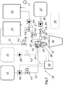
- Fig. 1 is a greatly simplified scheme of a drinks vending machine according to an embodiment of the invention reproduced.
- the drinks machine 10 of the Fig. 1 is adapted to prepare from a base liquid, in particular milk or water, by mixing with a concentrated, liquid additive, in particular chocolate or syrup or the like., In a vessel, in particular a cup 16, a finished beverage.
- the concentrated, liquid additive and the base liquid are introduced separately into the vessel or the cup 16 and mix there automatically.
- the beverage dispenser 10 may additionally be designed for the preparation and dispensing of coffee drinks, in which case a coffee preparation unit 29 (in Fig. 1 dashed lines) is provided, which the coffee beverage, with milk, milk foam or a flavoring syrup may or may be added, prepared and dispensed into the cup 16.
- a coffee preparation unit 29 in Fig. 1 dashed lines
- the coffee beverage, with milk, milk foam or a flavoring syrup may or may be added, prepared and dispensed into the cup 16.
- the concentrated, liquid additive is kept in a separate reservoir 11, which may be formed, for example, as an exchangeable canister. Other additives can be kept ready in further storage containers (see in particular Fig. 2 ).
- Fig. 1 is (optional) another reservoir 12 shown in dashed lines. From each of the reservoir 11, 12 a line 23 and 24 leads to an outlet 19 to be discharged from there into the cup 16. In the example of Fig. 1 the same outlet 19 is used for the two reservoirs and the additives therein; in the example of Fig. 2 On the other hand, each of the five different additives (reservoir 11a-e) has its own outlet (19a-e).
- a suitable pump P1, P2 is arranged, which is driven by a motor and is controlled by a central control unit 22 (in Fig. 1
- a central control unit 22 in Fig. 1
- Suitable pumps are because of the predominantly relatively high viscosity of the additives, especially peristaltic pumps, which can be used at the same time for the exact dosage of the additives.
- Controllable valves V1, V2 can also be used in the lines 23, 24, for example, to prevent overrun of the additives safely.
- the viscosity of the additive prior to delivery into the cup 16 via the outlet 19 is done by heating the additive either by means of an electric heater 32 or by means of hot steam in a arranged upstream of the outlet 19 Auffilvoriques 30.
- this heating device 30 of the one of the reservoir 11, 12 by means of the associated pump P1 or P2 funded additive by heated electrical heating or by thermal contact with or by direct mixing of hot steam, so that it comparatively thin liquid from the outlet 19 passes into the cup 16 below and there automatically mixed with the simultaneously filled base liquid.
- the reduction of the viscosity is effected on the one hand by the heating of the additive, and on the other hand by a certain degree of dilution with the water vapor condensing in the additive.
- the electric heater 32 is supplied, for example, from the central control unit 22 in a controlled manner with electrical energy.
- the steam introduced into the heating device 30 is preferably generated in a separate steam generator unit 13 and transported via an associated line 25 to the heating device 30.
- the steam generator unit 13 receives the water required for this purpose, for example from a water source 17, which may be formed as a water reservoir or as a water connection.
- the mixing and heating of the additive with the supplied via the line 25 (steam line) steam takes place when flowing through the heating device 30, so that the additive-steam mixture directly down to the subsequent outlet 19 exits.
- the outlet 19 can be "blown out" with a burst of steam via the line 25, whereby a dripping of the reduced viscosity in the additive is largely avoided.
- rinsing of the lines and channels acted upon by the additive can subsequently be provided in the heating device 30 and in the outlet 19 arranged behind by a rinsing liquid.
- a rinsing liquid is especially water, especially hot or hot water, in question, which is already present in a drinks vending machine, the hot drinks water-based such as coffee, soups, mulled wine or the like.
- a corresponding Wasseraufloomologist 14 (hot water heater, boiler) is then connected via a line 26 (hot water) to the heating device 30, so that introduced via a arranged in the line 26 valve V4 by means of a pump P3 hot water into the heating device 30 and the entire line section to to the bottom the outlet 19 can be flushed through inside.
- This process is also controlled by the control unit 22 via the pump P3 and the valve V4. It is expedient to feed the hot water used for rinsing between the valve V3 and the heating device 30 in the (steam) line 25.
- the water heating unit 14 may be replaced with a water tank.
- an additional "external rinse” is provided for the case that the outlet 19 is formed as a jacketed outlet, in which an inner tube 21 for the additive is concentrically surrounded by an outer shell 20.
- the annular space between the inner tube 21 and outer shell 20 can then be used to rid the free end of the inner tube 21 of externally adhering additive residues, encrustations, etc., with a rinsing fluid conveyed through the annular space.
- a further line 27 is branched off from the line 26 for the hot water and led via a controllable valve V5 to the heating device 30, where the hot water is fed into the annular space between inner tube 21 and outer casing 20 of the outlet 19.
- the flushing connection can also be arranged directly on the outlet 19.
- a chocolate drink is to be prepared, cold or hot milk is fed into the cup 16 through a separate milk dispenser unit 18 to the heated chocolate additive which is delivered from a milk source 15 to the milk dispenser unit 18 via a line 28 by a pump P4.
- the milk source 15 may comprise a reservoir for milk. But it can also produce the milk from a concentrate or milk powder by mixing with cold or hot water.
- Cold milk can be heated within the milk source 15, eg in a continuous flow heater or by adding hot steam. It is also conceivable, cold milk on the way to To heat milk dispensing unit 18 (in Fig.1 not shown).
- a controlled valve V6 in line 28 controls milk flow in addition to pump P4.
- FIG. 2 is the simplified scheme for the supply of five different additives in a beverage vending machine 10 'given again.
- Each of the additives is associated with its own storage tank 11a-e, its own heating device 30a-e and its own outlet 19a-e. This reliably prevents contamination of one additive by another.
- Each additive is conveyed via its own line with a pump P1a-e and a valve V1a-e to the corresponding heating device 30a-e, where it is mixed with steam from the steam generator unit 13 and heated.
- valves V3a-e are provided for the control of the steam supply.
- the line coming from the water heating unit 14 can optionally be switched via corresponding valves V4a-e to the hot steam lines leading from the steam generator unit 13 to the outlets 19a-e.
- An appropriate external rinse as in Fig. 1 is plotted for reasons of space only for the outlet 19a and via a valve V5a.
- the other outlets 19b-e can be flushed out in an analogous manner.
- it is also conceivable to provide for all outlets 19a-e by connecting all the annular spaces between inner tube and outer shell a common external flush, which is controlled only via a valve and, if necessary, all outlets 1 9a-e flushes together.
- the individual spouts 19a-e are in Fig. 2 for reasons of clarity in a row next to each other. However, in the actual drinks vending machines, they are spatially grouped together (eg, arranged in two parallel rows or in a ring shape) so that they can all dispense the heated additive into a cup underneath without having to move the cup. Of course, in this arrangement also the (in Fig. 2 not shown) milk dispensing unit 18 and other existing outlets in the machine (eg for coffee drinks) integrated.
- the present invention provides the following approach: Shortly before dispensing, the liquid chocolate is brought to a higher temperature with additional steam so as to lower the viscosity and facilitate mixing with the milk. The amount of steam must be adjusted so that the chocolate is not burned and the correct temperature is reached.
- the chocolate spout can be "blown out” with the steam and the dripping at the outlet is thereby reduced.
- water can also be introduced into the outlet via the steam path so as to allow an (internal) flushing.
- an external flushing of the spout can be provided.
Landscapes
- Engineering & Computer Science (AREA)
- Food Science & Technology (AREA)
- Apparatus For Making Beverages (AREA)
- Beverage Vending Machines With Cups, And Gas Or Electricity Vending Machines (AREA)
- Devices For Dispensing Beverages (AREA)
Description
Die vorliegende Erfindung bezieht sich auf das Gebiet der Getränkeautomaten. Sie betrifft ein Verfahren zum Zubereiten eines Mischgetränkes gemäss dem Oberbegriff des Anspruchs 1.The present invention relates to the field of vending machines. It relates to a method for preparing a mixed beverage according to the preamble of
Sie betrifft weiterhin einen Getränkeautomaten zur Durchführung des Verfahrens.It further relates to a drinks vending machine for carrying out the method.
Beim Einsatz von flüssiger Schokolade zur Zubereitung eines Schokoladenmilchgetränks in einem Getränkeautomaten ergibt sich die Problematik des Vermischens mit der Milch. Diese Problematik kann entweder dadurch gelöst werden, dass der Kunde das Getränk am Schluss noch mit einem Rührgerät manuell mischt oder der Automat die Schokolade in einem speziellen Mischventil mit der Milch vermischt.The use of liquid chocolate to prepare a chocolate milk drink in a beverage vending machine results in the problem of mixing with the milk. This problem can be solved either by the fact that the customer mixes the drink at the end still with a stirrer manually or the machine mixes the chocolate in a special mixing valve with the milk.
Der Nachteil des Mischventils ist, dass zum einen eine Kontamination der Milch nicht ausgeschlossen werden kann und zum anderen das Ventil zum Verkleben neigt. Ebenfalls sind Anwendungen bekannt, bei denen der Schokoladenbehälter mittels Heizplatte auf eine bestimmte Temperatur gebracht wird. Aufgrund der langen Schläuche hat dies aber auf die Vermischung wenig Einfluss, weil die Schokolade auf dem Weg zum Vermischungsort wieder abkühlt.The disadvantage of the mixing valve is that on the one hand a contamination of the milk can not be excluded and on the other hand, the valve tends to stick. Also known are applications in which the chocolate container is brought to a specific temperature by means of a heating plate. Due to the long hoses, however, this has little influence on the mixing because the chocolate cools again on the way to the mixing place.
Dokument
Dokument
Die Vorrichtung umfasst einen Tank mit dem konzentrierten flüssigen Produkt zur Zubereitung des Getränkes, eine Verbindereinheit, die an den Tank angeschlossen ist, eine Pumpe, die so angeordnet ist, dass sie eine vorbestimmte Menge des konzentrierten Produktes aus dem Tank zur Verbindereinheit fördert, eine Wasseraufheizeinheit mit einem Einlass und einem Auslass für das Wasser und einem Einlass zum Einführen des Dampfes, eine Wasserzuführleitung, die den Einlass der Wasseraufheizeinheit mit einer Wasserquelle verbindet, ein Absperrventil in der Wasserzuführleitung, eine Leitung zur Verbindung des Auslasses für das aufgeheizte Wasser aus der Wasseraufheizeinheit mit der Verbindereinheit, um in diese eine vorbestimmte Menge Wasser einzuleiten, eine Dampfleitung zur Verbindung des Dampferzeuger mit dem Einlass für den Dampf, ein Ventil in der Dampfleitung, eine Getränkezubereitungseinheit mit einem zugehörigen Auslass, die mit der Verbindereinheit und der Quelle für die Milch verbunden ist. Das konzentrierte flüssige Produkt basiert insbesondere auf Schokolade. Nachteilig ist hierbei, dass das Schokoladenprodukt vor der Ausgabe in einer speziellen Einrichtung mit der Milch direkt vermischt wird. In der Mischeinheit ist einerseits eine unerwünschte Kontamination der Milch möglich. Andererseits kann die Mischeinheit verkleben.The apparatus comprises a tank of the concentrated liquid product for making the beverage, a connector unit connected to the tank, a pump arranged to receive a predetermined amount of the concentrated product from the tank to the connector unit, a water heating unit having an inlet and an outlet for the water and an inlet for introducing the steam, a water supply pipe connecting the inlet of the water heating unit to a water source, a shutoff valve in the water supply pipe, a pipe for connecting the water Outlet for the heated water from the water heating unit with the connector unit to introduce into this a predetermined amount of water, a steam line for connection of the steam generator with the inlet for the steam, a valve in the steam line, a beverage preparation unit with an associated outlet, with the Connector unit and the source of the milk is connected. The concentrated liquid product is based in particular on chocolate. The disadvantage here is that the chocolate product is mixed directly with the milk before being dispensed in a special facility. On the one hand, undesired contamination of the milk is possible in the mixing unit. On the other hand, the mixing unit can stick together.
Dokument
Dokument
Es ist daher eine Aufgabe der Erfindung, ein Verfahren zum Zubereiten eines Mischgetränkes aus einer Basisflüssigkeit und einem konzentrierten, flüssigen Zusatzstoff anzugeben, welches die Nachteile bekannter Verfahren vermeidet und sich insbesondere dadurch auszeichnet, dass es einfach und sicher ausführbar ist und Fehlfunktionen einer entsprechenden Maschine durch Verschmutzung oder Zusetzen wirkungsvoll vermeidet.It is therefore an object of the invention to provide a method for preparing a mixed beverage of a base liquid and a concentrated liquid additive, which avoids the disadvantages of known methods and in particular characterized in that it is simple and safe executable and malfunction of a corresponding machine by Effectively avoids contamination or clogging.
Es ist weiterhin Aufgabe der Erfindung, einen Getränkerautomaten zur Durchführung des Verfahrens anzugeben.It is a further object of the invention to provide a beverage dispenser for performing the method.
Diese und andere Aufgaben werden durch die Merkmale der Ansprüche 1 und 14 gelöst.These and other objects are achieved by the features of
Beim Verfahren gemäss der Erfindung zum Zubereiten eines Mischgetränkes aus einer Basisflüssigkeit und einem konzentrierten, flüssigen Zusatzstoff, welcher dem Mischgetränk einen speziellen Geschmack verleiht, wird der konzentrierte, flüssige Zusatzstoff aus einem Vorratsbehälter entnommen, anschliessend durch Zufuhr von Energie erhitzt und der erhitzte konzentrierte, flüssige Zusatzstoff dann mit der Basisflüssigkeit vermischt, wobei der erhitzte konzentrierte, flüssige Zusatzstoff und die Basisflüssigkeit über separate Ausläufe in ein darunter stehendes Gefäss, insbesondere einen Becher, ausgegeben werden und sich dort selbsttätig vermischen.In the method according to the invention for preparing a mixed beverage from a base liquid and a concentrated liquid additive which gives the mixed drink a special taste, the concentrated liquid additive is removed from a storage container, then heated by supplying energy and the heated concentrated, liquid Add additive then mixed with the base liquid, with the heated concentrated, liquid additive and the base liquid over separate outlets in an underlying vessel, in particular a cup, are spent and there automatically mix.
Gemäss einer Ausgestaltung des erfindungsgemässen Verfahrens wird der konzentrierte, flüssige Zusatzstoff in einer vorbestimmten Menge aus dem Vorratsbehälter (entnommen und über eine zugehörige Leitung mittels einer in der Leitung angeordneten Pumpe einer Aufheizvorrichtung zugeführt, wobei der Aufheizvorrichtung soviel Energie zugeführt wird, dass der konzentrierte, flüssige Zusatzstoff auf eine vorbestimmte Temperatur aufgeheizt wird.According to one embodiment of the inventive method, the concentrated, liquid additive in a predetermined amount from the reservoir (taken and fed via an associated line by means of a pump arranged in the line of a heating device, the heater is supplied so much energy that the concentrated, liquid Additive is heated to a predetermined temperature.
Insbesondere weist die Aufheizvorrichtung eine elektrische Heizung auf, wobei die Energie als elektrische Energie zugeführt wird.In particular, the heating device has an electric heater, wherein the energy is supplied as electrical energy.
Alternativ wird der Aufheizvorrichtung die Energie in Form von heissem Dampf zugeführt, wobei der Dampf in einer Dampferzeugereinheit erzeugt und über eine zugehörige Leitung der Aufheizvorrichtung zugeführt wird.Alternatively, the heating device is supplied with the energy in the form of hot steam, wherein the steam is generated in a steam generator unit and fed to the heating device via an associated line.
Insbesondere wird der zugeführte Dampf in der Aufheizvorrichtung mit dem konzentrierten, flüssigen Zusatzstoff vermischt.In particular, the supplied steam is mixed in the heating device with the concentrated, liquid additive.
Insbesondere erfolgt die Mischung von Dampf und konzentriertem, flüssigen Zusatzstoff und die damit verbundene Erhitzung des konzentrierten, flüssigen Zusatzstoffs während des Durchlaufs des konzentrierten, flüssigen Zusatzstoffs durch die Aufheizvorrichtung.In particular, the mixture of steam and concentrated liquid additive and the associated heating of the concentrated liquid additive during the passage of the concentrated liquid additive through the heating device.
Es ist grundsätzlich aber auch denkbar, dass die Mischung von Dampf und konzentriertem, flüssigen Zusatzstoff und die damit verbundene Erhitzung des konzentrierten, flüssigen Zusatzstoffs in der Aufheizvorrichtung erfolgt, und dass der aufgeheizte konzentrierte, flüssige Zusatzstoff anschliessend aus der Aufheizvorrichtung ausgegeben wird.In principle, however, it is also conceivable for the mixture of steam and concentrated, liquid additive and the associated heating of the concentrated, liquid additive to take place in the heating device, and for the heated, concentrated additive subsequently to be dispensed from the heating device.
Vorzugsweise wird die Temperatur des erhitzten konzentrierten, flüssigen Zusatzstoffs mittels eines in der Aufheizvorrichtung angeordneten Temperaturaufnehmers gemessen und überwacht.Preferably, the temperature of the heated concentrated liquid additive is measured and monitored by means of a temperature pick-up arranged in the heating device.
Eine andere Ausgestaltung des erfindungsgemässen Verfahrens zeichnet sich dadurch aus, dass der erhitzte konzentrierte, flüssige Zusatzstoff und die Basisflüssigkeit gleichzeitig in das darunter stehendes Gefäss ausgegeben werden.Another embodiment of the method according to the invention is characterized in that the heated concentrated, liquid additive and the base liquid are dispensed simultaneously into the vessel below.
Eine weitere Ausgestaltung des erfindungsgemässen Verfahrens ist dadurch gekennzeichnet, dass der erhitzte konzentrierte, flüssige Zusatzstoff Schokolade umfasst, und dass die Basisflüssigkeit Milch ist.A further embodiment of the method according to the invention is characterized in that the heated, concentrated additive comprises chocolate, and in that the base fluid is milk.
Eine wieder andere Ausgestaltung des erfindungsgemässen Verfahrens ist dadurch gekennzeichnet, dass der erhitzte konzentrierte, flüssige Zusatzstoff einen Sirup umfasst, und dass die Basisflüssigkeit Wasser ist.Yet another embodiment of the inventive method is characterized in that the heated concentrated, liquid additive comprises a syrup, and that the base liquid is water.
Eine noch andere Ausgestaltung des erfindungsgemässen Verfahrens ist dadurch gekennzeichnet, dass der Auslauf für den konzentrierten, flüssigen Zusatzstoff nach der Ausgabe des erhitzten konzentrierten, flüssigen Zusatzstoffs in das darunter stehendes Gefäss mit zusätzlichem Dampf aus der Dampferzeugereinheit durchgeblasen wird.Yet another embodiment of the method according to the invention is characterized in that the outlet for the concentrated, liquid additive is blown out of the steam generator unit with additional steam after the heated concentrated, liquid additive has been dispensed into the vessel below it.
Eine weitere Ausgestaltung des erfindungsgemässen Verfahrens ist dadurch gekennzeichnet, dass der Auslauf für den konzentrierten, flüssigen Zusatzstoff nach der Ausgabe des erhitzten konzentrierten, flüssigen Zusatzstoffs in das darunter stehendes Gefäss mit einer Spülflüssigkeit durchgespült wird.A further embodiment of the method according to the invention is characterized in that the outlet for the concentrated, liquid additive is flushed through with a rinsing liquid after the heated concentrated, liquid additive has been dispensed into the vessel below it.
Insbesondere wird als Spülflüssigkeit Wasser verwendet.In particular, water is used as the rinsing liquid.
Vorzugsweise wird als Spülflüssigkeit heisses Wasser verwendet, welches aus einer Wasseraufheizeinheit über eine zugehörige Leitung dem Auslauf zugeführt wird.Preferably, hot water is used as rinsing liquid, which is supplied from a Wasseraufheizeinheit via an associated line to the outlet.
Vorzugsweise wird der Auslauf für den konzentrierten, flüssigen Zusatzstoff nach der Ausgabe des erhitzten konzentrierten, flüssigen Zusatzstoffs in das darunter stehendes Gefäss mit Wasser durchgespült, wobei das zum Spülen verwendete Wasser in eine von der Dampferzeugereinheit zur Aufheizvorrichtung führende Leitung eingeführt wird.Preferably, after the heated concentrated liquid additive is dispensed into the vessel below, the concentrated liquid additive spout is flushed with water, with the water used for rinsing being introduced into a conduit leading from the boiler unit to the heater.
Besonderes vorteilhaft ist es, wenn der Auslauf für den konzentrierten, flüssigen Zusatzstoff einen Aussenmantel und ein konzentrisch darin angeordnetes Innenrohr für den Transport des konzentrierten, flüssigen Zusatzstoffes umfasst, und wenn zum Spülen der Aussenseite des Innenrohres Spülflüssigkeit zwischen Aussenmantel und Innenrohr nach aussen abgegeben wird.It is particularly advantageous if the outlet for the concentrated, liquid additive comprises an outer jacket and an inner tube arranged concentrically therein for transporting the concentrated, liquid additive, and if for flushing the outer side of the inner tube, flushing liquid is dispensed between outer jacket and inner tube to the outside.
Der erfindungsgemässe Getränkeautomat zur Durchführung des Verfahrens nach der Erfindung umfasst wenigstens einen Vorratsbehälter für den konzentrierten, flüssigen Zusatzstoff zur Zubereitung des Mischgetränkes, Mittel zur Zuführung einer vorbestimmten Menge Basisflüssigkeit für das zuzubereitende Mischgetränk, und wenigstens eine Aufheizvorrichtung, die einen ersten Eingang aufweist, der über eine erste Leitung mit dem wenigstens einen Vorratsbehälter in Verbindung steht, wobei die wenigstens eine Aufheizvorrichtung zur Aufheizung des über die erste Leitung zugeführten konzentrierten, flüssigen Zusatzstoffes durch eine zugeführte Energie ausgebildet ist. Sie ist dadurch gekennzeichnet, dass eine erste Vorrichtung vorgesehen ist, über welche die Basisflüssigkeit in einen darunter stehenden Behälter, insbesondere Becher ausgegeben werden kann, und dass eine zweite, von der ersten getrennte Vorrichtung vorgesehen ist, über welche der erhitzte konzentrierte, flüssige Zusatzstoff in den darunter stehenden Behälter ausgegeben werden kann.The beverage dispenser according to the invention for carrying out the method according to the invention comprises at least one storage container for the concentrated, liquid additive for preparing the mixed beverage, means for supplying a predetermined amount of base liquid for the mixed beverage to be prepared, and at least one heating device having a first input via a first conduit is in communication with the at least one reservoir, wherein the at least one heating device is configured to heat the concentrated, liquid additive supplied via the first conduit by an applied energy. It is characterized in that a first device is provided, via which the base liquid can be dispensed into an underlying container, in particular cup, and that a second, provided by the first separate device, via which the heated concentrated, liquid additive in the container below can be issued.
Eine Ausgestaltung des erfindungsgemässen Getränkeautomaten ist dadurch gekennzeichnet, dass die zweite Vorrichtung wenigstens einen Auslauf umfasst, der mit einem Ausgang der wenigstens einen Aufheizvorrichtung in direkter Verbindung steht.An embodiment of the beverage machine according to the invention is characterized in that the second device comprises at least one outlet, which is in direct communication with an outlet of the at least one heating device.
Eine andere Ausgestaltung des erfindungsgemässen Getränkeautomaten ist dadurch gekennzeichnet, dass in der ersten Leitung Mittel zum Fördern des konzentrierten, flüssigen Zusatzstoffes, insbesondere in Form einer Pumpe, angeordnet sind.Another embodiment of the beverage machines according to the invention is characterized in that in the first line means for conveying the concentrated, liquid additive, in particular in the form of a pump, are arranged.
Gemäss einer weiteren Ausgestaltung ist in der Aufheizvorrichtung zur Aufheizung des über die erste Leitung zugeführten konzentrierten, flüssigen Zusatzstoffes eine elektrische Heizung angeordnet.According to a further embodiment, an electric heater is arranged in the heating device for heating the concentrated, liquid additive supplied via the first line.
Es ist aber auch denkbar, dass eine Dampferzeugereinheit zur Erzeugung von Dampf zur Aufheizung des konzentrierten, flüssigen Zusatzstoffes vorgesehen ist, dass die Aufheizvorrichtung einen zweiten Eingang aufweist, der über eine zweite Leitung an die Dampferzeugereinheit angeschlossen ist, und dass in der zweiten Leitung ein erstes steuerbares Ventil zur Steuerung der Menge des der Aufheizvorrichtung zugeführten Dampfes angeordnet ist.But it is also conceivable that a steam generator unit for generating steam for heating the concentrated, liquid additive is provided, that the heating device has a second input, which is connected via a second line to the steam generator unit, and that in the second line a first controllable valve for controlling the amount of the heating device supplied steam is arranged.
Eine weitere Ausgestaltung des erfindungsgemässen Getränkeautomaten ist dadurch gekennzeichnet, dass in der zweiten Leitung ein erstes steuerbares Ventil zur Steuerung der Menge des der Aufheizvorrichtung zugeführten Dampfes angeordnet ist.A further embodiment of the beverage machines according to the invention is characterized in that a first controllable valve for controlling the amount of steam supplied to the heating device is arranged in the second line.
Insbesondere ist eine Wasseraufheizeinheit vorgesehen, deren Ausgang über eine dritte Leitung mit der zweiten Vorrichtung in Verbindung steht.In particular, a Wasseraufheizeinheit is provided, whose output is connected via a third line to the second device in connection.
Vorzugsweise mündet die dritte Leitung zwischen dem ersten steuerbaren Ventil und der Aufheizvorrichtung in die zweite Leitung.Preferably, the third line opens between the first controllable valve and the heating device in the second line.
Vorzugsweise ist in der dritten Leitung eine Pumpe zum Fördern des Wassers aus der Wasseraufheizeinheit angeordnet.Preferably, a pump for conveying the water from the Wasseraufheizeinheit is arranged in the third line.
Besonderes vorteilhaft ist es, wenn die zweite Vorrichtung wenigstens einen Auslauf umfasst, der mit einem Ausgang der wenigstens einen Aufheizvorrichtung in direkter Verbindung steht, wenn der wenigstens eine Auslauf einen Aussenmantel und ein konzentrisch darin angeordnetes Innenrohr für den Transport des konzentrierten, flüssigen Zusatzstoffes umfasst, und wenn zum Spülen der Aussenseite des Innenrohres eine vierte Leitung den Ausgang der Wasseraufheizeinheit mit dem Raum zwischen Aussenmantel und Innenrohr verbindet.It is particularly advantageous if the second device comprises at least one outlet which is in direct communication with an outlet of the at least one heating device, if the at least one outlet comprises an outer casing and an inner tube arranged concentrically therein for the transport of the concentrated, liquid additive, and if for flushing the outside of the inner tube, a fourth line connects the output of Wasseraufheizeinheit with the space between the outer shell and inner tube.
Vorzugsweise zweigt die vierte Leitung von der dritten Leitung stromabwärts der Pumpe ab.Preferably, the fourth conduit branches off the third conduit downstream of the pump.
Eine andere Ausgestaltung des erfindungsgemässen Getränkeautomaten ist dadurch gekennzeichnet, dass mehrere Vorratsbehälter für unterschiedliche konzentrierte, flüssigen Zusatzstoffe vorgesehen sind, dass jedem der Vorratsbehälter eine eigene Aufheizvorrichtung und eine eigene zweite Vorrichtung zugeordnet sind, und dass jede Aufheizvorrichtung über eine zugehörige erste Leitung mit dem zugehörigen Vorratsbehälter in Verbindung steht.Another embodiment of the beverage machines according to the invention is characterized in that a plurality of reservoirs are provided for different concentrated, liquid additives, that each of the reservoir own heating device and a separate second device are assigned, and that each heating device via an associated first line with the associated reservoir communicates.
Eine noch andere Ausgestaltung des erfindungsgemässen Getränkeautomaten ist dadurch gekennzeichnet, dass eine Steuereinheit zur automatischen Steuerung der Förder-, Aufheiz- und Ausgabevorgänge vorgesehen ist.Yet another embodiment of the beverage machines according to the invention is characterized in that a control unit is provided for the automatic control of the conveying, heating and dispensing operations.
Die Erfindung soll nachfolgend anhand von Ausführungsbeispielen im Zusammenhang mit der Zeichnung näher erläutert werden. Es zeigen:
- Fig. 1
- ein stark vereinfachtes Schema eines Getränkeautomaten gemäss einem Ausführungsbeispiel der Erfindung mit einem Auslauf für mehrere Zusatzstoffe; und
- Fig. 2
- ein stark vereinfachtes Schema eines Getränkeautomaten gemäss einem anderen Ausführungsbeispiel der Erfindung mit einem separaten Auslauf für jeden der mehreren Zusatzstoffe.
- Fig. 1
- a greatly simplified scheme of a beverage vending machine according to an embodiment of the invention with an outlet for a plurality of additives; and
- Fig. 2
- a greatly simplified scheme of a beverage vending machine according to another embodiment of the invention with a separate outlet for each of the multiple additives.
In
Der Getränkeautomat 10 kann zusätzlich auch zur Zubereitung und Abgabe von Kaffeegetränken ausgelegt sein, in welchem Falle eine Kaffeezubereitungseinheit 29 (in
Der konzentrierte, flüssige Zusatzstoff wird in einem eigenen Vorratsbehälter 11 bereitgehalten, der beispielsweise als austauschbarer Kanister ausgebildet sein kann. Weitere Zusatzstoffe können in weiteren Vorratsbehältern bereit gehalten werden (siehe insbesondere
Zur Förderung der konzentrierten, flüssigen Zusatzstoffe ist in jeder der Leitungen 23, 24 vorzugsweise eine geeignete Pumpe P1, P2 angeordnet, die motorisch angetrieben ist und von einer zentralen Steuereinheit 22 aus gesteuert wird (in
Da die Viskosität der Zusatzstoffe aus den Vorratsbehältern 11, 12, insbesondere auch im Fall von Schokolade als Zusatzstoff, vergleichsweise hoch ist, würde bei einer einfachen Ausgabe in den Becher 16 eine Mischung mit der zugegebenen Basisflüssigkeit, im Falle der Schokolade mit der Milch, nicht oder nur sehr unvollständig stattfinden. Ein nachträgliches Umrühren des Becherinhaltes wäre unvermeidlich, ist aber im Hinblick auf eine einfache Bedienung des Gerätes in hohem Masse unerwünscht.Since the viscosity of the additives from the
Es wird daher bei der hier erläuterten Lösung die Viskosität des Zusatzstoffes vor der Abgabe in den Becher 16 über den Auslauf 19 deutlich herabgesetzt. Dies geschieht durch Aufheizen des Zusatzstoffes entweder mittels einer elektrischen Heizung 32 oder mittels heissem Dampf in einer vor dem Auslauf 19 angeordneten Aufheizvorrichtung 30. In dieser Aufheizvorrichtung 30 wird der aus einem der Vorratsbehälter 11, 12 mittels der zugehörigen Pumpe P1 bzw. P2 geförderte Zusatzstoff durch elektrisches Aufheizen oder durch thermischen Kontakt mit oder durch direktes Zumischen von heissem Dampf erhitzt, so dass er vergleichsweise dünnflüssig aus dem Auslauf 19 in den darunter stehenden Becher 16 gelangt und sich dort selbsttätig mit der gleichzeitig eingefüllten Basisflüssigkeit vermischt. Die Herabsetzung der Viskosität wird dabei einerseits durch die Erhitzung des Zusatzstoffes bewirkt, und andererseits durch ein gewisses Mass an Verdünnung mit dem im Zusatzstoff kondensierenden Wasserdampf.It is therefore significantly reduced in the illustrated solution here, the viscosity of the additive prior to delivery into the
Die elektrische Heizung 32 wird beispielsweise von der zentralen Steuereinheit 22 in kontrollierter Weise mit elektrischer Energie versorgt. Im Falle der Aufheizung durch Dampf wird der in die Aufheizvorrichtung 30 eingeführte Dampf vorzugsweise in einer separaten Dampferzeugereinheit 13 erzeugt und über eine zugehörige Leitung 25 zur Aufheizvorrichtung 30 transportiert. Die Dampferzeugereinheit 13 erhält das dazu benötigte Wasser beispielsweise aus einer Wasserquelle 17, die als Wasservorratsbehälter oder als Wasseranschluss ausgebildet sein kann. Die Vermischung und Aufheizung des Zusatzstoffes mit dem über die Leitung 25 (Dampfleitung) zugeführten Dampf erfolgt beim Durchströmen der Aufheizvorrichtung 30, so dass die Zusatzstoff-Dampf-Mischung unmittelbar nach unten in den anschliessenden Auslauf 19 austritt. Es ist grundsätzlich aber auch denkbar, in der Aufheizvorrichtung 30 eine vorgegebene Menge Zusatzstoff durch Zugabe von Dampf aufzuheizen und erst nach Erreichen einer vorgegebenen Temperatur nach unten in den Auslauf 19 herauszulassen. In beiden Fällen kann die erreichte Temperatur des aufgeheizten Zusatzstoffes mittels eines an oder in der Aufheizvorrichtung 30 angeordneten Temperaturaufnehmers 31 gemessen und zu Steuerungszwecken an die Steuereinheit 22 übermittelt werden. Die Zufuhr des Dampfes zur Aufheizvorrichtung wird dabei durch ein steuerbares Ventil V3 gesteuert, das in der (Dampf-)Leitung 25 angeordnet ist und von der Steuereinheit 22 aktiviert wird. Ebenso ist es denkbar, den durch ein Rohr fliessenden Zusatzstoff durch aussen an das Rohr herangeführten heissen Dampf indirekt aufzuheizen.The
Ist das Aufheizen der vorbestimmten Menge an Zusatzstoff beendet und der aufgeheizte Zusatzstoff in den Becher 16 ausgegeben, kann der Auslauf 19 mit einem Dampfstoss über die Leitung 25 "ausgeblasen" werden, wodurch ein Nachtropfen des in der Viskosität herabgesetzten Zusatzstoffes weitgehend vermieden wird.If the heating of the predetermined amount of additive is complete and the heated additive is dispensed into the
Zusätzlich zu dem "Ausblasen" mittels Dampfstoss kann nachträglich ein Spülen der mit dem Zusatzstoff beaufschlagten Leitungen und Kanäle in der Aufheizvorrichtung 30 und im dahinter angeordneten Auslauf 19 durch eine Spülflüssigkeit vorgesehen werden. Als Spülflüssigkeit kommt dabei vor allem Wasser, insbesondere warmes oder heisses Wasser, in Frage, das bei einem Getränkeautomaten, der Heissgetränke auf Wasserbasis wie z.B. Kaffee, Suppen, Glühwein oder dgl. zubereitet, ohnehin vorhanden ist. Ein entsprechende Wasseraufheizeinheit 14 (Heisswasserbereiter, Boiler) ist dann über eine Leitung 26 (Heisswasserleitung) an die Aufheizvorrichtung 30 angeschlossen, so dass über ein in der Leitung 26 angeordnetes Ventil V4 mittels einer Pumpe P3 Heisswasser in die Aufheizvorrichtung 30 eingeführt und der gesamte Leitungsabschnitt bis zum unteren Ende des Auslaufs 19 innen durchgespült werden kann. Auch dieser Vorgang wird von der Steuereinheit 22 über die Pumpe P3 und das Ventil V4 gesteuert. Es ist dabei zweckmässig, das zum Spülen verwendete Heisswasser zwischen dem Ventil V3 und der Aufheizvorrichtung 30 in die (Dampf-)Leitung 25 einzuspeisen. Wird zum Spülen kaltes Wasser verwendet, kann die Wasseraufheizeinheit 14 durch einen Wasserbehälter ersetzt werden.In addition to the "blow-out" by means of steam injection, rinsing of the lines and channels acted upon by the additive can subsequently be provided in the
Eine zusätzliche "Aussenspülung" ist für den Fall vorgesehen, dass der Auslauf 19 als ummantelter Auslauf ausgebildet ist, bei dem ein Innenrohr 21 für den Zusatzstoff konzentrisch von einem Aussenmantel 20 umgeben ist. Der ringförmige Zwischenraum zwischen Innenrohr 21 und Aussenmantel 20 kann dann dazu eingesetzt werden, mit einer durch den Ringraum geförderten Spülflüssigkeit das freie Ende des Innenrohres 21 von aussen anhaftenden Zusatzstoffresten, Verkrustungen etc. zu befreien. Hierzu wird im Beispiel der
Soll ein Schokoladengetränk zubereitet werden, wird durch eine separate Milchausgabeeinheit 18 zu dem erhitzten Schokoladen-Zusatzstoff kalte oder heisse Milch in den Becher 16 eingefüllt, die aus einer Milchquelle 15 über eine Leitung 28 mittels einer Pumpe P4 zur Milchausgabeeinheit 18 gefördert wird. Die Milchquelle 15 kann einen Vorratsbehälter für Milch umfassen. Sie kann aber auch die Milch aus einem Konzentrat oder Milchpulver durch Vermischen mit kaltem oder heissem Wasser erzeugen. Kalte Milch kann innerhalb der Milchquelle 15 z.B. in einem Durchlauferhitzer oder durch Zugabe von Heissdampf erhitzt werden. Es ist aber auch denkbar, kalte Milch auf dem Weg zur Milchausgabeeinheit 18 zu erhitzen (in
In
Für die Innenspülung der Innenrohre in den Ausläufen 19a-e kann die von der Wasseraufheizeinheit 14 kommende Leitung wahlweise über entsprechende Ventile V4a-e auf die von der Dampferzeugereinheit 13 zu den Ausläufen 19a-e führenden Heissdampfleitungen geschaltet werden. Eine entsprechende Aussenspülung wie in
Die einzelnen Ausläufe 19a-e sind in
Für die Zubereitung eines Schokoladenmilchgetränks ergibt sich nach der vorliegenden Erfindung der folgende Lösungsweg: Kurz vor der Ausgabe wird die flüssige Schokolade mit zusätzlichem Dampf auf eine höhere Temperatur gebracht, um so die Viskosität zu erniedrigen und das Vermischen mit der Milch zu erleichtern. Die Dampfmenge muss so abgestimmt sein, dass die Schokolade nicht verbrannt wird und die korrekte Temperatur erreicht wird.For the preparation of a chocolate milk beverage, the present invention provides the following approach: Shortly before dispensing, the liquid chocolate is brought to a higher temperature with additional steam so as to lower the viscosity and facilitate mixing with the milk. The amount of steam must be adjusted so that the chocolate is not burned and the correct temperature is reached.
Vorteil dieser Lösung ist unter Anderem, dass der Schokoladen-Auslauf mit dem Dampf "ausgeblasen" werden kann und das Nachtropfen am Auslauf dadurch vermindert wird.Advantage of this solution is, among other things, that the chocolate spout can be "blown out" with the steam and the dripping at the outlet is thereby reduced.
Zusätzlich kann über den Dampfpfad auch Wasser in den Auslauf eingebracht werden, um so eine (innere) Spülung zu ermöglichen. Darüber hinaus kann auch eine äussere Spülung des Auslaufs vorgesehen werden.In addition, water can also be introduced into the outlet via the steam path so as to allow an (internal) flushing. In addition, an external flushing of the spout can be provided.
Nebst Schokolade kann man mit der Erfindung selbstverständlich auch andere Zusatzstoffe bzw. Zutaten wie z.B. Sirup, Sake, Glühwein oder ähnliches aufheizen.In addition to chocolate, it is of course also possible to heat up other additives or ingredients such as syrup, sake, mulled wine or the like with the invention.
- 10,10'10.10 '
- GetränkeautomatVending Machine
- 11,1211.12
- Vorratsbehälter (für fl. Schokolade, Sirup etc.)Storage container (for chocolate, syrup etc.)
- 11a-e11a-e
- Vorratsbehälterreservoir
- 1313
- DampferzeugereinheitSteam generator unit
- 1414
- WasseraufheizeinheitWasseraufheizeinheit
- 1515
- MilchquelleMilchquelle
- 1616
- Bechercup
- 1717
- Wasserquellewater source
- 1818
- MilchausgabeeinheitMilk output unit
- 1919
- Auslaufoutlet
- 19a-e19a-e
- Auslaufoutlet
- 2020
- Aussenmantelsheath
- 2121
- Innenrohrinner tube
- 2222
- Steuereinheitcontrol unit
- 23-2823-28
- Leitungmanagement
- 2929
- KaffeezubereitungseinheitCoffee-making unit
- 3030
- Aufheizvorrichtungheating device
- 30a-e30a-e
- Aufheizvorrichtungheating device
- 3131
- Temperaturaufnehmertemperature sensor
- 3232
- Heizung (elektrisch)Heating (electric)
- P1-P4P1-P4
- Pumpepump
- P1a-eP1a-e
- Pumpepump
- V1-V6V1-V6
- VentilValve
- V1a-eV 1a-e
- VentilValve
- V3a-eV3a-e
- VentilValve
- V4a-eV4a-e
- VentilValve
- V5aV5a
- VentilValve
Claims (21)
- A method for preparing a mixed beverage from a base liquid and a concentrated liquid additive that imparts a special taste to the mixed beverage, in which method the concentrated liquid additive is withdrawn from a storage container (11, 12; 11a-e) and is subsequently heated by supplying energy, and the heated, concentrated liquid additive is then mixed with the base liquid, characterized in that the heated, concentrated liquid additive and the base liquid are dispensed via separate outflow spouts (18, 19; 19a-e) into a container, in particular a cup (16), situated underneath, where they automatically mix with each other.
- The method according to Claim 1, characterized in that the concentrated liquid additive is withdrawn in a predetermined quantity from the storage container (11, 12; 11a-e) and is supplied to a heating device (30; 30a-e) via an associated line (23, 24) by means of a pump (P1, P2; P1a-e) situated in the line (23, 24), and that such an amount of energy is supplied to the heating device (30; 30a-e) that the concentrated liquid additive is heated to a predetermined temperature.
- The method according to Claim 2, characterized in that the heating device (30; 30a-e) comprises an electric heater (32), and that the energy is supplied as electrical energy.
- The method according to Claim 2, characterized in that the energy is supplied to the heating device (30; 30a-e) in the form of hot steam, that the steam is generated in a steam generator unit (13) and is supplied to the heating device (30; 30a-e) via an associated line (25), that the supplied steam is mixed with the concentrated liquid additive in the heating device (30; 30a-e), and that the mixing of steam and concentrated liquid additive and the associated heating of the concentrated liquid additive take place while the concentrated liquid additive passes through the heating device (30; 30a-e).
- The method according to Claim 2, characterized in that the temperature of the heated, concentrated liquid additive is measured and monitored by means of a temperature sensor (31) situated in the heating device (30; 30a-e).
- The method according to Claim 1, characterized in that the heated, concentrated liquid additive and the base liquid are simultaneously dispensed into the container (16) situated underneath.
- The method according to Claim 1, characterized in that the heated, concentrated liquid additive comprises chocolate, and that the base liquid is milk.
- The method according to Claim 1, characterized in that the heated, concentrated liquid additive comprises a syrup, and that the base liquid is water.
- The method according to Claim 2, characterized in that the energy is supplied to the heating device (30; 30a-e) in the form of hot steam, that the steam is generated in a steam generator unit (13) and supplied to the heating device (30; 30a-e) via an associated line (25), and that additional steam from the steam generator unit (13) is blown through the outflow spout (19; 19a-e) for the concentrated liquid additive after the heated, concentrated liquid additive is dispensed into the container (16) situated underneath.
- The method according to Claim 1, characterized in that the outflow spout (19; 19a-e) for the concentrated liquid additive is flushed with a flushing liquid after the heated, concentrated liquid additive is dispensed into the container (16) situated underneath, and that hot water, which is supplied to the outflow spout (19; 19a-e) from a water heating unit (14) via an associated line, is used as flushing liquid.
- The method according to Claim 2, characterized in that the energy is supplied to the heating device (30; 30a-e) in the form of hot steam, that the steam is generated in a steam generator unit (13) and is supplied to the heating device (30; 30a-e) via an associated line (25), that the supplied steam is mixed with the concentrated liquid additive in the heating device (30; 30a-e), and that the outflow spout (19; 19a-e) for the concentrated liquid additive is flushed with water after the heated, concentrated liquid additive is dispensed into the container (16) situated underneath, and that the water used for flushing is introduced into a line (25) that leads from the steam generator unit (13) to the heating device (30; 30a-e).
- The method according to Claim 1, characterized in that the outflow spout (19; 19a-e) for the concentrated liquid additive is flushed with a flushing liquid after the heated, concentrated liquid additive is dispensed into the container (16) situated underneath, that the outflow spout (19; 19a-e) for the concentrated liquid additive comprises an outer jacket (20) and an inner tube (21), situated concentrically therein, for transporting the concentrated liquid additive, and that flushing liquid is delivered to the outside, between the outer jacket (20) and the inner tube (21), in order to flush the outer side of the inner tube (21).
- An automatic beverage machine (10) for carrying out the method according to Claim 1, comprising at least one storage container (11, 12; 11a-e) for the concentrated liquid additive for preparing the mixed beverage, means (15, 28, P4, V6) for supplying a predetermined quantity of base liquid for the mixed beverage to be prepared, and at least one heating device (30; 30a-e) that has a first inlet that is connected to the at least one storage container (11, 12; 11a-e) via a first line (23, 24), wherein the at least one heating device (30; 30a-e) is designed for heating the concentrated liquid additive, supplied via the first line (23, 24), by means of supplied energy, characterized in that a first apparatus (18) is provided via which the base liquid may be dispensed into a container, in particular a cup (16), situated underneath, and that a second apparatus (19, 20, 21; 19a-e), separate from the first apparatus, is provided via which the heated, concentrated liquid additive may be dispensed into the container (16) situated underneath.
- The automatic beverage machine according to Claim 13, characterized in that the second apparatus comprises at least one outflow spout (19; 19a-e) that is directly connected to an outlet of the at least one heating device (30; 30a-e).
- The automatic beverage machine according to Claim 13, characterized in that means for conveying the concentrated liquid additive, in particular in the form of a pump (P1, P2; P1a-e), are situated in the first line (23, 24).
- The automatic beverage machine according to Claim 13, characterized in that an electric heater (32) is situated in the heating device (30; 30a-e) for heating the concentrated liquid additive that is supplied via the first line (23, 24).
- The automatic beverage machine according to Claim 13, characterized in that a steam generator unit (13) for generating steam for heating the concentrated liquid additive is provided, that the heating device (30; 30a-e) has a second inlet that is connected to the steam generator unit (13) via a second line (25), that a first controllable valve (V3; V3a-e) for controlling the quantity of steam supplied to the heating device (30; 30a-e) is situated in the second line (25), and that a water heating unit (14) is provided whose outlet is connected to the second apparatus (19, 20, 21; 19a-e) via a third line (26).
- The automatic beverage machine according to Claim 17, characterized in that the third line (26) opens into the second line (25) between the first controllable valve (V3; V3a-e) and the heating device (30; 30a-e).
- The automatic beverage machine according to Claim 17, characterized in that a pump (P3) for conveying the water from the water heating unit (14) is situated in the third line (26), that the second apparatus comprises at least one outflow spout (19; 19a-e) that is directly connected to an outlet of the at least one heating device (30; 30a-e), that the at least one outflow spout (19; 19a-e) comprises an outer jacket (20) and an inner tube (21), situated concentrically therein, for transporting the concentrated liquid additive, that for flushing the outer side of the inner tube (21), a fourth line (27) connects the outlet of the water heating unit (14) to the space between the outer jacket (20) and the inner tube (21), and that the fourth line (27) branches off from the third line (26) downstream from the pump (P3).
- The automatic beverage machine according to Claim 13, characterized in that multiple storage containers (11, 12; 11a-e) are provided for different concentrated liquid additives, that a separate heating device (30; 30a-e) and a separate second apparatus (19, 20, 21; 19a-e) are associated with each of the storage containers (11, 12; 11a-e), and that each heating device (30; 30a-e) is connected to the associated storage container (11, 12; 11a-e) via an associated first line (23, 24).
- The automatic beverage machine according to Claim 13, characterized in that a control unit (22) is provided for automatically controlling the conveying, heating, and dispensing operations.
Applications Claiming Priority (2)
| Application Number | Priority Date | Filing Date | Title |
|---|---|---|---|
| CH00860/13A CH707966A1 (en) | 2013-04-25 | 2013-04-25 | Method for preparing a mix beverage and vending machine for performing the method. |
| PCT/EP2014/053183 WO2014173555A1 (en) | 2013-04-25 | 2014-02-19 | Method for preparing a mixed beverage, and automatic beverage machine for carrying out the method |
Publications (2)
| Publication Number | Publication Date |
|---|---|
| EP2988635A1 EP2988635A1 (en) | 2016-03-02 |
| EP2988635B1 true EP2988635B1 (en) | 2019-04-03 |
Family
ID=48534099
Family Applications (1)
| Application Number | Title | Priority Date | Filing Date |
|---|---|---|---|
| EP14705502.4A Active EP2988635B1 (en) | 2013-04-25 | 2014-02-19 | Method for preparing a mixed beverage, and automatic beverage machine for carrying out the method |
Country Status (3)
| Country | Link |
|---|---|
| EP (1) | EP2988635B1 (en) |
| CH (1) | CH707966A1 (en) |
| WO (1) | WO2014173555A1 (en) |
Families Citing this family (3)
| Publication number | Priority date | Publication date | Assignee | Title |
|---|---|---|---|---|
| US10329135B2 (en) * | 2015-08-17 | 2019-06-25 | Nestec S.A. | Anti-dripping system |
| DE102016213141A1 (en) * | 2016-07-19 | 2018-01-25 | Bayerische Motoren Werke Aktiengesellschaft | Filling system |
| US12096875B2 (en) * | 2020-02-04 | 2024-09-24 | The Quaker Oats Company | System and apparatus for providing cooked food |
Family Cites Families (5)
| Publication number | Priority date | Publication date | Assignee | Title |
|---|---|---|---|---|
| US2954145A (en) * | 1955-03-08 | 1960-09-27 | Raymond E Mccauley | Beverage making machine |
| EP2086377A1 (en) * | 2006-11-14 | 2009-08-12 | Koninklijke Philips Electronics N.V. | Calibration arrangement for an apparatus that prepares a beverage from water and an instant product |
| EP2050368B1 (en) | 2007-10-16 | 2010-04-14 | Gruppo Cimbali S.p.A. | Coffee machine with dispenser of a ready prepared chocolate-based beverage |
| EP2236063B1 (en) | 2007-11-19 | 2013-05-29 | Gruppo Cimbali S.p.A. | Method for preparing and dispensing a beverage, in particular a chocolate-based beverage in a coffee machine |
| US9402502B2 (en) | 2010-07-02 | 2016-08-02 | Luigi Lavazza S.P.A. | Hot-beverage-making apparatus, in particular for milk beverages such as cappuccino, chocolate and the like |
-
2013
- 2013-04-25 CH CH00860/13A patent/CH707966A1/en not_active Application Discontinuation
-
2014
- 2014-02-19 WO PCT/EP2014/053183 patent/WO2014173555A1/en active Application Filing
- 2014-02-19 EP EP14705502.4A patent/EP2988635B1/en active Active
Non-Patent Citations (1)
| Title |
|---|
| None * |
Also Published As
| Publication number | Publication date |
|---|---|
| WO2014173555A1 (en) | 2014-10-30 |
| EP2988635A1 (en) | 2016-03-02 |
| CH707966A1 (en) | 2014-10-31 |
Similar Documents
| Publication | Publication Date | Title |
|---|---|---|
| EP2030538B1 (en) | Method and device for preparing aromatic hot drinks, in particular coffee and tea | |
| EP2854608B1 (en) | Output unit for a beverage dispenser, beverage dispenser having such an output unit and method for operating such a beverage dispenser | |
| EP2011421B1 (en) | Device for issuing milk-based drinks | |
| EP2279149B1 (en) | Method and filling system for filling bottles or similar containers with a liquid product | |
| EP2157895B1 (en) | Drinks preparation device | |
| EP2158138B1 (en) | Beverage preparation apparatus with brewing unit and multi-portion container for powdered drink constituents | |
| EP2294952B1 (en) | Device for dispensing milk and/or milk foam | |
| EP2798989B1 (en) | Beverage preparation device with means for milk heating and operating procedure | |
| EP2494895B1 (en) | Method for discharging drinks from a beverage machine | |
| EP2190327B1 (en) | Device for producing and dispensing beverages mixed from milk with liquid flavoring agents | |
| EP2157892A1 (en) | Brewing unit of a device for preparing beverages | |
| WO2007014654A1 (en) | Coffee machine | |
| WO2010017888A1 (en) | Method for bottling a fill material consisting of at least one first and one second component | |
| EP3099208B1 (en) | Flavor module and method for operating such a flavor module | |
| EP3870005B1 (en) | Method for creating a coffee beverage in a coffee machine | |
| EP2988635B1 (en) | Method for preparing a mixed beverage, and automatic beverage machine for carrying out the method | |
| EP2388064A1 (en) | Method and device for mixing drinks | |
| DE202014102435U1 (en) | Self-service vending machine | |
| WO2021073809A1 (en) | Method and appliance for producing beverages, preferably foamed milk or milk beverages | |
| WO2024184321A1 (en) | Beverage dispensing machine comprising a cleaning device | |
| AT504103B1 (en) | Coffee machine also dispenses other drinks, e.g. milk, and has heating block for these drinks which contains chamber connected to steam supply and linked by several transverse bores to U-shaped channel, through which drink flows | |
| DE202011051696U1 (en) | Device for dispensing a steam-heated flowable food |
Legal Events
| Date | Code | Title | Description |
|---|---|---|---|
| PUAI | Public reference made under article 153(3) epc to a published international application that has entered the european phase |
Free format text: ORIGINAL CODE: 0009012 |
|
| 17P | Request for examination filed |
Effective date: 20150930 |
|
| AK | Designated contracting states |
Kind code of ref document: A1 Designated state(s): AL AT BE BG CH CY CZ DE DK EE ES FI FR GB GR HR HU IE IS IT LI LT LU LV MC MK MT NL NO PL PT RO RS SE SI SK SM TR |
|
| AX | Request for extension of the european patent |
Extension state: BA ME |
|
| DAX | Request for extension of the european patent (deleted) | ||
| GRAP | Despatch of communication of intention to grant a patent |
Free format text: ORIGINAL CODE: EPIDOSNIGR1 |
|
| STAA | Information on the status of an ep patent application or granted ep patent |
Free format text: STATUS: GRANT OF PATENT IS INTENDED |
|
| INTG | Intention to grant announced |
Effective date: 20180828 |
|
| GRAS | Grant fee paid |
Free format text: ORIGINAL CODE: EPIDOSNIGR3 |
|
| GRAA | (expected) grant |
Free format text: ORIGINAL CODE: 0009210 |
|
| STAA | Information on the status of an ep patent application or granted ep patent |
Free format text: STATUS: THE PATENT HAS BEEN GRANTED |
|
| AK | Designated contracting states |
Kind code of ref document: B1 Designated state(s): AL AT BE BG CH CY CZ DE DK EE ES FI FR GB GR HR HU IE IS IT LI LT LU LV MC MK MT NL NO PL PT RO RS SE SI SK SM TR |
|
| REG | Reference to a national code |
Ref country code: GB Ref legal event code: FG4D Free format text: NOT ENGLISH |
|
| REG | Reference to a national code |
Ref country code: CH Ref legal event code: EP Ref country code: AT Ref legal event code: REF Ref document number: 1114693 Country of ref document: AT Kind code of ref document: T Effective date: 20190415 |
|
| REG | Reference to a national code |
Ref country code: DE Ref legal event code: R096 Ref document number: 502014011308 Country of ref document: DE |
|
| REG | Reference to a national code |
Ref country code: IE Ref legal event code: FG4D Free format text: LANGUAGE OF EP DOCUMENT: GERMAN |
|
| REG | Reference to a national code |
Ref country code: CH Ref legal event code: NV Representative=s name: IPRIME RENTSCH KAELIN AG, CH |
|
| REG | Reference to a national code |
Ref country code: NL Ref legal event code: FP |
|
| REG | Reference to a national code |
Ref country code: LT Ref legal event code: MG4D |
|
| PG25 | Lapsed in a contracting state [announced via postgrant information from national office to epo] |
Ref country code: AL Free format text: LAPSE BECAUSE OF FAILURE TO SUBMIT A TRANSLATION OF THE DESCRIPTION OR TO PAY THE FEE WITHIN THE PRESCRIBED TIME-LIMIT Effective date: 20190403 Ref country code: CZ Free format text: LAPSE BECAUSE OF FAILURE TO SUBMIT A TRANSLATION OF THE DESCRIPTION OR TO PAY THE FEE WITHIN THE PRESCRIBED TIME-LIMIT Effective date: 20190403 Ref country code: ES Free format text: LAPSE BECAUSE OF FAILURE TO SUBMIT A TRANSLATION OF THE DESCRIPTION OR TO PAY THE FEE WITHIN THE PRESCRIBED TIME-LIMIT Effective date: 20190403 Ref country code: SE Free format text: LAPSE BECAUSE OF FAILURE TO SUBMIT A TRANSLATION OF THE DESCRIPTION OR TO PAY THE FEE WITHIN THE PRESCRIBED TIME-LIMIT Effective date: 20190403 Ref country code: NO Free format text: LAPSE BECAUSE OF FAILURE TO SUBMIT A TRANSLATION OF THE DESCRIPTION OR TO PAY THE FEE WITHIN THE PRESCRIBED TIME-LIMIT Effective date: 20190703 Ref country code: PT Free format text: LAPSE BECAUSE OF FAILURE TO SUBMIT A TRANSLATION OF THE DESCRIPTION OR TO PAY THE FEE WITHIN THE PRESCRIBED TIME-LIMIT Effective date: 20190803 Ref country code: HR Free format text: LAPSE BECAUSE OF FAILURE TO SUBMIT A TRANSLATION OF THE DESCRIPTION OR TO PAY THE FEE WITHIN THE PRESCRIBED TIME-LIMIT Effective date: 20190403 Ref country code: FI Free format text: LAPSE BECAUSE OF FAILURE TO SUBMIT A TRANSLATION OF THE DESCRIPTION OR TO PAY THE FEE WITHIN THE PRESCRIBED TIME-LIMIT Effective date: 20190403 Ref country code: LT Free format text: LAPSE BECAUSE OF FAILURE TO SUBMIT A TRANSLATION OF THE DESCRIPTION OR TO PAY THE FEE WITHIN THE PRESCRIBED TIME-LIMIT Effective date: 20190403 |
|
| PG25 | Lapsed in a contracting state [announced via postgrant information from national office to epo] |
Ref country code: LV Free format text: LAPSE BECAUSE OF FAILURE TO SUBMIT A TRANSLATION OF THE DESCRIPTION OR TO PAY THE FEE WITHIN THE PRESCRIBED TIME-LIMIT Effective date: 20190403 Ref country code: BG Free format text: LAPSE BECAUSE OF FAILURE TO SUBMIT A TRANSLATION OF THE DESCRIPTION OR TO PAY THE FEE WITHIN THE PRESCRIBED TIME-LIMIT Effective date: 20190703 Ref country code: RS Free format text: LAPSE BECAUSE OF FAILURE TO SUBMIT A TRANSLATION OF THE DESCRIPTION OR TO PAY THE FEE WITHIN THE PRESCRIBED TIME-LIMIT Effective date: 20190403 Ref country code: GR Free format text: LAPSE BECAUSE OF FAILURE TO SUBMIT A TRANSLATION OF THE DESCRIPTION OR TO PAY THE FEE WITHIN THE PRESCRIBED TIME-LIMIT Effective date: 20190704 Ref country code: PL Free format text: LAPSE BECAUSE OF FAILURE TO SUBMIT A TRANSLATION OF THE DESCRIPTION OR TO PAY THE FEE WITHIN THE PRESCRIBED TIME-LIMIT Effective date: 20190403 |
|
| PG25 | Lapsed in a contracting state [announced via postgrant information from national office to epo] |
Ref country code: IS Free format text: LAPSE BECAUSE OF FAILURE TO SUBMIT A TRANSLATION OF THE DESCRIPTION OR TO PAY THE FEE WITHIN THE PRESCRIBED TIME-LIMIT Effective date: 20190803 |
|
| REG | Reference to a national code |
Ref country code: DE Ref legal event code: R097 Ref document number: 502014011308 Country of ref document: DE |
|
| PG25 | Lapsed in a contracting state [announced via postgrant information from national office to epo] |
Ref country code: RO Free format text: LAPSE BECAUSE OF FAILURE TO SUBMIT A TRANSLATION OF THE DESCRIPTION OR TO PAY THE FEE WITHIN THE PRESCRIBED TIME-LIMIT Effective date: 20190403 Ref country code: DK Free format text: LAPSE BECAUSE OF FAILURE TO SUBMIT A TRANSLATION OF THE DESCRIPTION OR TO PAY THE FEE WITHIN THE PRESCRIBED TIME-LIMIT Effective date: 20190403 Ref country code: SK Free format text: LAPSE BECAUSE OF FAILURE TO SUBMIT A TRANSLATION OF THE DESCRIPTION OR TO PAY THE FEE WITHIN THE PRESCRIBED TIME-LIMIT Effective date: 20190403 Ref country code: EE Free format text: LAPSE BECAUSE OF FAILURE TO SUBMIT A TRANSLATION OF THE DESCRIPTION OR TO PAY THE FEE WITHIN THE PRESCRIBED TIME-LIMIT Effective date: 20190403 |
|
| PLBE | No opposition filed within time limit |
Free format text: ORIGINAL CODE: 0009261 |
|
| STAA | Information on the status of an ep patent application or granted ep patent |
Free format text: STATUS: NO OPPOSITION FILED WITHIN TIME LIMIT |
|
| PG25 | Lapsed in a contracting state [announced via postgrant information from national office to epo] |
Ref country code: SM Free format text: LAPSE BECAUSE OF FAILURE TO SUBMIT A TRANSLATION OF THE DESCRIPTION OR TO PAY THE FEE WITHIN THE PRESCRIBED TIME-LIMIT Effective date: 20190403 |
|
| 26N | No opposition filed |
Effective date: 20200106 |
|
| PG25 | Lapsed in a contracting state [announced via postgrant information from national office to epo] |
Ref country code: TR Free format text: LAPSE BECAUSE OF FAILURE TO SUBMIT A TRANSLATION OF THE DESCRIPTION OR TO PAY THE FEE WITHIN THE PRESCRIBED TIME-LIMIT Effective date: 20190403 |
|
| PG25 | Lapsed in a contracting state [announced via postgrant information from national office to epo] |
Ref country code: SI Free format text: LAPSE BECAUSE OF FAILURE TO SUBMIT A TRANSLATION OF THE DESCRIPTION OR TO PAY THE FEE WITHIN THE PRESCRIBED TIME-LIMIT Effective date: 20190403 |
|
| GBPC | Gb: european patent ceased through non-payment of renewal fee |
Effective date: 20200219 |
|
| REG | Reference to a national code |
Ref country code: BE Ref legal event code: MM Effective date: 20200229 |
|
| PG25 | Lapsed in a contracting state [announced via postgrant information from national office to epo] |
Ref country code: MC Free format text: LAPSE BECAUSE OF FAILURE TO SUBMIT A TRANSLATION OF THE DESCRIPTION OR TO PAY THE FEE WITHIN THE PRESCRIBED TIME-LIMIT Effective date: 20190403 Ref country code: LU Free format text: LAPSE BECAUSE OF NON-PAYMENT OF DUE FEES Effective date: 20200219 |
|
| PG25 | Lapsed in a contracting state [announced via postgrant information from national office to epo] |
Ref country code: FR Free format text: LAPSE BECAUSE OF NON-PAYMENT OF DUE FEES Effective date: 20200229 Ref country code: GB Free format text: LAPSE BECAUSE OF NON-PAYMENT OF DUE FEES Effective date: 20200219 Ref country code: IE Free format text: LAPSE BECAUSE OF NON-PAYMENT OF DUE FEES Effective date: 20200219 |
|
| PG25 | Lapsed in a contracting state [announced via postgrant information from national office to epo] |
Ref country code: BE Free format text: LAPSE BECAUSE OF NON-PAYMENT OF DUE FEES Effective date: 20200229 |
|
| PG25 | Lapsed in a contracting state [announced via postgrant information from national office to epo] |
Ref country code: MT Free format text: LAPSE BECAUSE OF FAILURE TO SUBMIT A TRANSLATION OF THE DESCRIPTION OR TO PAY THE FEE WITHIN THE PRESCRIBED TIME-LIMIT Effective date: 20190403 Ref country code: CY Free format text: LAPSE BECAUSE OF FAILURE TO SUBMIT A TRANSLATION OF THE DESCRIPTION OR TO PAY THE FEE WITHIN THE PRESCRIBED TIME-LIMIT Effective date: 20190403 |
|
| PG25 | Lapsed in a contracting state [announced via postgrant information from national office to epo] |
Ref country code: MK Free format text: LAPSE BECAUSE OF FAILURE TO SUBMIT A TRANSLATION OF THE DESCRIPTION OR TO PAY THE FEE WITHIN THE PRESCRIBED TIME-LIMIT Effective date: 20190403 |
|
| P01 | Opt-out of the competence of the unified patent court (upc) registered |
Effective date: 20230525 |
|
| PGFP | Annual fee paid to national office [announced via postgrant information from national office to epo] |
Ref country code: NL Payment date: 20240129 Year of fee payment: 11 |
|
| PGFP | Annual fee paid to national office [announced via postgrant information from national office to epo] |
Ref country code: AT Payment date: 20240124 Year of fee payment: 11 |
|
| PGFP | Annual fee paid to national office [announced via postgrant information from national office to epo] |
Ref country code: DE Payment date: 20240213 Year of fee payment: 11 Ref country code: CH Payment date: 20240301 Year of fee payment: 11 |
|
| PGFP | Annual fee paid to national office [announced via postgrant information from national office to epo] |
Ref country code: IT Payment date: 20240207 Year of fee payment: 11 |