EP2987604A1 - Dispositif et procédé de recyclage à vide dans une installation de traitement de récipient - Google Patents
Dispositif et procédé de recyclage à vide dans une installation de traitement de récipient Download PDFInfo
- Publication number
- EP2987604A1 EP2987604A1 EP14181649.6A EP14181649A EP2987604A1 EP 2987604 A1 EP2987604 A1 EP 2987604A1 EP 14181649 A EP14181649 A EP 14181649A EP 2987604 A1 EP2987604 A1 EP 2987604A1
- Authority
- EP
- European Patent Office
- Prior art keywords
- vacuum
- pressure
- recycling
- reservoir
- region
- Prior art date
- Legal status (The legal status is an assumption and is not a legal conclusion. Google has not performed a legal analysis and makes no representation as to the accuracy of the status listed.)
- Granted
Links
- 238000004064 recycling Methods 0.000 title claims abstract description 92
- 238000000034 method Methods 0.000 title claims description 34
- 230000001105 regulatory effect Effects 0.000 claims abstract description 10
- 238000011049 filling Methods 0.000 claims description 77
- 230000015654 memory Effects 0.000 claims description 76
- 239000004033 plastic Substances 0.000 claims description 26
- 238000000465 moulding Methods 0.000 claims description 19
- 238000007664 blowing Methods 0.000 claims description 9
- 238000004891 communication Methods 0.000 claims description 6
- 230000003247 decreasing effect Effects 0.000 claims description 5
- 238000003860 storage Methods 0.000 abstract description 36
- 239000000047 product Substances 0.000 description 24
- 238000011161 development Methods 0.000 description 22
- 230000018109 developmental process Effects 0.000 description 22
- 238000000071 blow moulding Methods 0.000 description 12
- 239000012530 fluid Substances 0.000 description 10
- 238000005429 filling process Methods 0.000 description 7
- 239000007789 gas Substances 0.000 description 7
- 239000007788 liquid Substances 0.000 description 7
- 238000011109 contamination Methods 0.000 description 5
- 238000004519 manufacturing process Methods 0.000 description 5
- 238000007493 shaping process Methods 0.000 description 5
- XLYOFNOQVPJJNP-UHFFFAOYSA-N water Substances O XLYOFNOQVPJJNP-UHFFFAOYSA-N 0.000 description 5
- 238000012937 correction Methods 0.000 description 4
- MHAJPDPJQMAIIY-UHFFFAOYSA-N Hydrogen peroxide Chemical compound OO MHAJPDPJQMAIIY-UHFFFAOYSA-N 0.000 description 3
- 235000013361 beverage Nutrition 0.000 description 3
- 238000013461 design Methods 0.000 description 3
- 238000004659 sterilization and disinfection Methods 0.000 description 3
- CURLTUGMZLYLDI-UHFFFAOYSA-N Carbon dioxide Chemical compound O=C=O CURLTUGMZLYLDI-UHFFFAOYSA-N 0.000 description 2
- 238000004140 cleaning Methods 0.000 description 2
- 238000000576 coating method Methods 0.000 description 2
- 229910052500 inorganic mineral Inorganic materials 0.000 description 2
- 239000000463 material Substances 0.000 description 2
- 238000010327 methods by industry Methods 0.000 description 2
- 239000011707 mineral Substances 0.000 description 2
- 230000001954 sterilising effect Effects 0.000 description 2
- 241001295925 Gegenes Species 0.000 description 1
- 239000002253 acid Substances 0.000 description 1
- 208000002352 blister Diseases 0.000 description 1
- 229910002092 carbon dioxide Inorganic materials 0.000 description 1
- 239000001569 carbon dioxide Substances 0.000 description 1
- 239000000969 carrier Substances 0.000 description 1
- 239000011248 coating agent Substances 0.000 description 1
- 150000001875 compounds Chemical class 0.000 description 1
- 238000004320 controlled atmosphere Methods 0.000 description 1
- 230000007423 decrease Effects 0.000 description 1
- 238000009826 distribution Methods 0.000 description 1
- 238000005265 energy consumption Methods 0.000 description 1
- 238000005516 engineering process Methods 0.000 description 1
- 238000000605 extraction Methods 0.000 description 1
- 230000006870 function Effects 0.000 description 1
- 238000002347 injection Methods 0.000 description 1
- 239000007924 injection Substances 0.000 description 1
- 238000001746 injection moulding Methods 0.000 description 1
- 238000003780 insertion Methods 0.000 description 1
- 230000037431 insertion Effects 0.000 description 1
- 239000012212 insulator Substances 0.000 description 1
- 235000021056 liquid food Nutrition 0.000 description 1
- 239000012263 liquid product Substances 0.000 description 1
- 239000002184 metal Substances 0.000 description 1
- 238000002156 mixing Methods 0.000 description 1
- 238000002360 preparation method Methods 0.000 description 1
- 238000004321 preservation Methods 0.000 description 1
- 238000012545 processing Methods 0.000 description 1
- 238000005086 pumping Methods 0.000 description 1
- 238000011084 recovery Methods 0.000 description 1
- 239000007787 solid Substances 0.000 description 1
- 238000005507 spraying Methods 0.000 description 1
- 238000010025 steaming Methods 0.000 description 1
- 238000012360 testing method Methods 0.000 description 1
- 238000012546 transfer Methods 0.000 description 1
- 238000011144 upstream manufacturing Methods 0.000 description 1
Images


Classifications
-
- B—PERFORMING OPERATIONS; TRANSPORTING
- B29—WORKING OF PLASTICS; WORKING OF SUBSTANCES IN A PLASTIC STATE IN GENERAL
- B29C—SHAPING OR JOINING OF PLASTICS; SHAPING OF MATERIAL IN A PLASTIC STATE, NOT OTHERWISE PROVIDED FOR; AFTER-TREATMENT OF THE SHAPED PRODUCTS, e.g. REPAIRING
- B29C49/00—Blow-moulding, i.e. blowing a preform or parison to a desired shape within a mould; Apparatus therefor
- B29C49/42—Component parts, details or accessories; Auxiliary operations
- B29C49/4284—Means for recycling or reusing auxiliaries or materials, e.g. blowing fluids or energy
-
- F—MECHANICAL ENGINEERING; LIGHTING; HEATING; WEAPONS; BLASTING
- F04—POSITIVE - DISPLACEMENT MACHINES FOR LIQUIDS; PUMPS FOR LIQUIDS OR ELASTIC FLUIDS
- F04F—PUMPING OF FLUID BY DIRECT CONTACT OF ANOTHER FLUID OR BY USING INERTIA OF FLUID TO BE PUMPED; SIPHONS
- F04F5/00—Jet pumps, i.e. devices in which flow is induced by pressure drop caused by velocity of another fluid flow
- F04F5/44—Component parts, details, or accessories not provided for in, or of interest apart from, groups F04F5/02 - F04F5/42
- F04F5/48—Control
-
- B—PERFORMING OPERATIONS; TRANSPORTING
- B65—CONVEYING; PACKING; STORING; HANDLING THIN OR FILAMENTARY MATERIAL
- B65B—MACHINES, APPARATUS OR DEVICES FOR, OR METHODS OF, PACKAGING ARTICLES OR MATERIALS; UNPACKING
- B65B3/00—Packaging plastic material, semiliquids, liquids or mixed solids and liquids, in individual containers or receptacles, e.g. bags, sacks, boxes, cartons, cans, or jars
- B65B3/02—Machines characterised by the incorporation of means for making the containers or receptacles
- B65B3/022—Making containers by moulding of a thermoplastic material
-
- B—PERFORMING OPERATIONS; TRANSPORTING
- B65—CONVEYING; PACKING; STORING; HANDLING THIN OR FILAMENTARY MATERIAL
- B65B—MACHINES, APPARATUS OR DEVICES FOR, OR METHODS OF, PACKAGING ARTICLES OR MATERIALS; UNPACKING
- B65B31/00—Packaging articles or materials under special atmospheric or gaseous conditions; Adding propellants to aerosol containers
- B65B31/02—Filling, closing, or filling and closing, containers or wrappers in chambers maintained under vacuum or superatmospheric pressure or containing a special atmosphere, e.g. of inert gas
- B65B31/022—Filling, closing, or filling and closing, containers or wrappers in chambers maintained under vacuum or superatmospheric pressure or containing a special atmosphere, e.g. of inert gas the chambers moving in an endless path
-
- B—PERFORMING OPERATIONS; TRANSPORTING
- B65—CONVEYING; PACKING; STORING; HANDLING THIN OR FILAMENTARY MATERIAL
- B65B—MACHINES, APPARATUS OR DEVICES FOR, OR METHODS OF, PACKAGING ARTICLES OR MATERIALS; UNPACKING
- B65B39/00—Nozzles, funnels or guides for introducing articles or materials into containers or wrappers
- B65B39/14—Nozzles, funnels or guides for introducing articles or materials into containers or wrappers movable with a moving container or wrapper during filling or depositing
- B65B39/145—Nozzles, funnels or guides for introducing articles or materials into containers or wrappers movable with a moving container or wrapper during filling or depositing in an endless path
-
- F—MECHANICAL ENGINEERING; LIGHTING; HEATING; WEAPONS; BLASTING
- F04—POSITIVE - DISPLACEMENT MACHINES FOR LIQUIDS; PUMPS FOR LIQUIDS OR ELASTIC FLUIDS
- F04F—PUMPING OF FLUID BY DIRECT CONTACT OF ANOTHER FLUID OR BY USING INERTIA OF FLUID TO BE PUMPED; SIPHONS
- F04F5/00—Jet pumps, i.e. devices in which flow is induced by pressure drop caused by velocity of another fluid flow
- F04F5/14—Jet pumps, i.e. devices in which flow is induced by pressure drop caused by velocity of another fluid flow the inducing fluid being elastic fluid
- F04F5/16—Jet pumps, i.e. devices in which flow is induced by pressure drop caused by velocity of another fluid flow the inducing fluid being elastic fluid displacing elastic fluids
-
- B—PERFORMING OPERATIONS; TRANSPORTING
- B29—WORKING OF PLASTICS; WORKING OF SUBSTANCES IN A PLASTIC STATE IN GENERAL
- B29C—SHAPING OR JOINING OF PLASTICS; SHAPING OF MATERIAL IN A PLASTIC STATE, NOT OTHERWISE PROVIDED FOR; AFTER-TREATMENT OF THE SHAPED PRODUCTS, e.g. REPAIRING
- B29C49/00—Blow-moulding, i.e. blowing a preform or parison to a desired shape within a mould; Apparatus therefor
- B29C49/42—Component parts, details or accessories; Auxiliary operations
- B29C49/48—Moulds
- B29C2049/4879—Moulds characterised by mould configurations
- B29C2049/4892—Mould halves consisting of an independent main and bottom part
-
- B—PERFORMING OPERATIONS; TRANSPORTING
- B29—WORKING OF PLASTICS; WORKING OF SUBSTANCES IN A PLASTIC STATE IN GENERAL
- B29C—SHAPING OR JOINING OF PLASTICS; SHAPING OF MATERIAL IN A PLASTIC STATE, NOT OTHERWISE PROVIDED FOR; AFTER-TREATMENT OF THE SHAPED PRODUCTS, e.g. REPAIRING
- B29C49/00—Blow-moulding, i.e. blowing a preform or parison to a desired shape within a mould; Apparatus therefor
- B29C49/42—Component parts, details or accessories; Auxiliary operations
- B29C49/62—Venting means
- B29C2049/622—Venting means for venting air between preform and cavity, e.g. using venting holes, gaps or patterned moulds
- B29C2049/627—Venting means for venting air between preform and cavity, e.g. using venting holes, gaps or patterned moulds using vacuum means
-
- B—PERFORMING OPERATIONS; TRANSPORTING
- B29—WORKING OF PLASTICS; WORKING OF SUBSTANCES IN A PLASTIC STATE IN GENERAL
- B29C—SHAPING OR JOINING OF PLASTICS; SHAPING OF MATERIAL IN A PLASTIC STATE, NOT OTHERWISE PROVIDED FOR; AFTER-TREATMENT OF THE SHAPED PRODUCTS, e.g. REPAIRING
- B29C2791/00—Shaping characteristics in general
- B29C2791/004—Shaping under special conditions
- B29C2791/006—Using vacuum
-
- B—PERFORMING OPERATIONS; TRANSPORTING
- B29—WORKING OF PLASTICS; WORKING OF SUBSTANCES IN A PLASTIC STATE IN GENERAL
- B29C—SHAPING OR JOINING OF PLASTICS; SHAPING OF MATERIAL IN A PLASTIC STATE, NOT OTHERWISE PROVIDED FOR; AFTER-TREATMENT OF THE SHAPED PRODUCTS, e.g. REPAIRING
- B29C2949/00—Indexing scheme relating to blow-moulding
- B29C2949/07—Preforms or parisons characterised by their configuration
- B29C2949/0715—Preforms or parisons characterised by their configuration the preform having one end closed
-
- B—PERFORMING OPERATIONS; TRANSPORTING
- B29—WORKING OF PLASTICS; WORKING OF SUBSTANCES IN A PLASTIC STATE IN GENERAL
- B29C—SHAPING OR JOINING OF PLASTICS; SHAPING OF MATERIAL IN A PLASTIC STATE, NOT OTHERWISE PROVIDED FOR; AFTER-TREATMENT OF THE SHAPED PRODUCTS, e.g. REPAIRING
- B29C49/00—Blow-moulding, i.e. blowing a preform or parison to a desired shape within a mould; Apparatus therefor
- B29C49/02—Combined blow-moulding and manufacture of the preform or the parison
- B29C49/06—Injection blow-moulding
-
- B—PERFORMING OPERATIONS; TRANSPORTING
- B29—WORKING OF PLASTICS; WORKING OF SUBSTANCES IN A PLASTIC STATE IN GENERAL
- B29C—SHAPING OR JOINING OF PLASTICS; SHAPING OF MATERIAL IN A PLASTIC STATE, NOT OTHERWISE PROVIDED FOR; AFTER-TREATMENT OF THE SHAPED PRODUCTS, e.g. REPAIRING
- B29C49/00—Blow-moulding, i.e. blowing a preform or parison to a desired shape within a mould; Apparatus therefor
- B29C49/08—Biaxial stretching during blow-moulding
- B29C49/10—Biaxial stretching during blow-moulding using mechanical means for prestretching
- B29C49/12—Stretching rods
-
- B—PERFORMING OPERATIONS; TRANSPORTING
- B29—WORKING OF PLASTICS; WORKING OF SUBSTANCES IN A PLASTIC STATE IN GENERAL
- B29C—SHAPING OR JOINING OF PLASTICS; SHAPING OF MATERIAL IN A PLASTIC STATE, NOT OTHERWISE PROVIDED FOR; AFTER-TREATMENT OF THE SHAPED PRODUCTS, e.g. REPAIRING
- B29C49/00—Blow-moulding, i.e. blowing a preform or parison to a desired shape within a mould; Apparatus therefor
- B29C49/28—Blow-moulding apparatus
- B29C49/30—Blow-moulding apparatus having movable moulds or mould parts
- B29C49/36—Blow-moulding apparatus having movable moulds or mould parts rotatable about one axis
-
- B—PERFORMING OPERATIONS; TRANSPORTING
- B29—WORKING OF PLASTICS; WORKING OF SUBSTANCES IN A PLASTIC STATE IN GENERAL
- B29C—SHAPING OR JOINING OF PLASTICS; SHAPING OF MATERIAL IN A PLASTIC STATE, NOT OTHERWISE PROVIDED FOR; AFTER-TREATMENT OF THE SHAPED PRODUCTS, e.g. REPAIRING
- B29C49/00—Blow-moulding, i.e. blowing a preform or parison to a desired shape within a mould; Apparatus therefor
- B29C49/42—Component parts, details or accessories; Auxiliary operations
- B29C49/4284—Means for recycling or reusing auxiliaries or materials, e.g. blowing fluids or energy
- B29C49/42845—Recycling or reusing of fluid, e.g. pressure
- B29C49/42855—Blowing fluids, e.g. reducing fluid consumption
-
- B—PERFORMING OPERATIONS; TRANSPORTING
- B29—WORKING OF PLASTICS; WORKING OF SUBSTANCES IN A PLASTIC STATE IN GENERAL
- B29C—SHAPING OR JOINING OF PLASTICS; SHAPING OF MATERIAL IN A PLASTIC STATE, NOT OTHERWISE PROVIDED FOR; AFTER-TREATMENT OF THE SHAPED PRODUCTS, e.g. REPAIRING
- B29C49/00—Blow-moulding, i.e. blowing a preform or parison to a desired shape within a mould; Apparatus therefor
- B29C49/42—Component parts, details or accessories; Auxiliary operations
- B29C49/58—Blowing means
-
- B—PERFORMING OPERATIONS; TRANSPORTING
- B65—CONVEYING; PACKING; STORING; HANDLING THIN OR FILAMENTARY MATERIAL
- B65B—MACHINES, APPARATUS OR DEVICES FOR, OR METHODS OF, PACKAGING ARTICLES OR MATERIALS; UNPACKING
- B65B2210/00—Specific aspects of the packaging machine
- B65B2210/06—Sterilising or cleaning machinery or conduits
- B65B2210/08—Cleaning nozzles, funnels or guides through which articles are introduced into containers or wrappers
-
- Y—GENERAL TAGGING OF NEW TECHNOLOGICAL DEVELOPMENTS; GENERAL TAGGING OF CROSS-SECTIONAL TECHNOLOGIES SPANNING OVER SEVERAL SECTIONS OF THE IPC; TECHNICAL SUBJECTS COVERED BY FORMER USPC CROSS-REFERENCE ART COLLECTIONS [XRACs] AND DIGESTS
- Y02—TECHNOLOGIES OR APPLICATIONS FOR MITIGATION OR ADAPTATION AGAINST CLIMATE CHANGE
- Y02P—CLIMATE CHANGE MITIGATION TECHNOLOGIES IN THE PRODUCTION OR PROCESSING OF GOODS
- Y02P70/00—Climate change mitigation technologies in the production process for final industrial or consumer products
- Y02P70/10—Greenhouse gas [GHG] capture, material saving, heat recovery or other energy efficient measures, e.g. motor control, characterised by manufacturing processes, e.g. for rolling metal or metal working
Definitions
- the invention relates to an apparatus and a method for vacuum recycling in a container treatment plant.
- the invention relates to such a device and method in the context of filling devices for filling containers, for example bottles, with a substantially liquid filling product, for.
- a beverage or a hygiene product blowing and Streckblasvoriquesen for the production of plastic containers, such as PET bottles, by applying appropriate preforms (preforms) with a compressed gas and combined Formphaliquesen for simultaneous molding and filling of plastic containers by filling the preform under pressure the filling product, in which a negative pressure in a vacuum chamber of the treatment station is generated in order to accelerate the molding and / or filling process.
- Filling devices for filling containers and blowing or stretch blow molding devices are well known in filling technology, in particular in beverage filling. Recently, mold filling machines have also been used for the simultaneous shaping and filling of plastic containers.
- plastic containers can be produced by stretch blow molding from preforms.
- the plastic containers before being expanded are preforms (preforms) which preferably have the shape of a test tube or have a single opening.
- a mouth region In the vicinity of this opening is a mouth region, which has been provided for example with an already molded by injection threads for a closure.
- a support ring may be provided in the mouth region, which is provided for transport.
- the EP 1529620 B1 a method for the hydraulic forming of preforms into plastic bottles.
- the preforms are first heated, placed in a mold and stretched there in the longitudinal direction.
- Mineral water or the like is further introduced under pressure to produce the final container shape.
- the mineral water remains in the container, so that a subsequent separate filling step is dispensable.
- the US 2011/0031659 A1 further describes a method in which a heated preform is stretched by means of a stretching rod and then by means of an incompressible fluid, in particular Water is hydraulically expanded to a container. Thereafter, the fluid is displaced by compressed air and drains from the container.
- an incompressible fluid in particular Water
- a mold-filling machine comprises at least one treatment station for expanding plastic preforms into plastic containers in a mold and for filling a substantially liquid product or at least one liquid or solid component of the product into the plastic containers.
- liquids including those containing dissolved carbon dioxide or the like, are by definition incompressible fluids in terms of their function in forming and filling the containers, as opposed to gases that are functionally defined as compressible fluids.
- the process of forming and / or filling can be accelerated by generating a partial vacuum in the process chamber, which is pressure-tight in the form of a vacuum chamber.
- the vacuum chamber After introducing the preform or container to be treated, however, the vacuum chamber must first be evacuated to the desired process pressure, which is generally done directly via a vacuum pump, which is connected to the vacuum chamber via corresponding suction lines. Upon reopening the vacuum chamber to remove the treated container, however, the vacuum thus created is lost by pressure equalization with the environment of the vacuum chamber, leaving much of the power applied by the vacuum pump unused.
- the present invention is therefore based on the object to use this unused part of the performance of the vacuum pump as optimally as possible. More generally, the present invention has for its object to improve the energy efficiency of the container treatment plant and to reduce the energy consumption of the vacuum pump. By reducing the vacuum pump, the system should also be made more compact.
- a device for vacuum recycling in a container treatment plant comprising a plurality of treatment stations, each having a closable vacuum area, a plurality of connecting lines which connect the vacuum areas with each other and / or with a central vacuum storage, and a control and / or control unit, which is designed such that a vacuum generated in a vacuum region is partially forwarded to another vacuum region and / or the vacuum reservoir.
- the term vacuum is to be understood as meaning that the pressure prevailing in the vacuum region is lower than the ambient pressure.
- the prevailing pressure may be in the range from 0.1 to 0.9 bar, preferably from 0.3 to 0.8 bar, more preferably from 0.5 to 0.7 bar.
- other pressure ranges for the vacuum are conceivable.
- the present invention is not explicitly limited to the aforementioned ranges, but is in principle applicable to any vacuum pressure.
- negative pressures of 0.1 to 0.4 bar in the vacuum range can be realized.
- the pressure in the vacuum range deviates from the pressure in the container immediately before filling by less than 0.2 bar. But it can also be the same pressure.
- a vacuum region here and below means a lockable volume of a treatment station for carrying out a treatment process on one or more containers and / or preforms, wherein the volume for carrying out the treatment process is evacuated to a pressure which is lower than the ambient pressure is.
- the environment through the environment of the container treatment plant or the interior of an insulator, d. H. Clean room be given.
- the ambient pressure will correspond to the atmospheric pressure.
- the treatment station can be, for example, a filling station for filling the containers, a molding machine, in particular a blow molding machine, one of the already mentioned mold filling machines, a coating station, or the like.
- the treatment process to be carried out the filling of a container with a filling product, in particular a liquid food, the molding of a plastic container by a blowing or stretch blow molding process, the molding and simultaneous filling of a plastic container by means of a liquid filling product, which simultaneously serves for molding, a vacuum-assisted coating process or the like.
- a filling product in particular a liquid food
- the molding of a plastic container by a blowing or stretch blow molding process the molding and simultaneous filling of a plastic container by means of a liquid filling product, which simultaneously serves for molding, a vacuum-assisted coating process or the like.
- the processes mentioned are known in principle in the prior art and are therefore not explained further here. It should merely be mentioned that the mentioned filling, shaping or Medformreae to support or accelerate the process in a partial vacuum, so be carried out at a negative pressure.
- vacuum is always used for the sake of simplicity, even if a significant residual pressure remains in the vacuum region.
- the filling process can be considerably accelerated by the fact that the interior of the container to be filled is evacuated before filling. This can be done in particular by filling the container to be filled in a closed chamber which has been evacuated before.
- a blow molding or stretch blow molding process can be assisted by applying a vacuum between the preform and the inner wall of the blow mold.
- the mold filling process can also be carried out in a vacuum chamber specially provided for this purpose.
- the vacuum region is lockable, d. H.
- the vacuum area refers to a pressure-sealed volume with one or more pressure-tight closable openings.
- the openings are provided in particular with a controllable or controllable closing device, such as a switchable valve, a switchable flap, a controllable slide or the like.
- a controllable or controllable closing device such as a switchable valve, a switchable flap, a controllable slide or the like.
- Other options are conceivable and known in the art. It is only important that the opening or the openings can be closed and opened in a controlled manner, so that a controlled atmosphere prevails within the vacuum area.
- the opening and closing of the closing devices takes place by means of a control and / or regulating unit, which is designed such that a vacuum generated in a vacuum region is partially forwarded to another vacuum region and / or the central vacuum reservoir.
- the vacuum areas are connected to each other and / or to the central vacuum area via a plurality of connecting lines, which can be opened and closed by switching closing devices provided on or in the connecting lines.
- a partial recycling of a vacuum in a vacuum region takes place according to the invention, in that the evacuated vacuum region is brought into hydrodynamic contact in a targeted manner via one of the connecting lines with a further vacuum region in which a higher pressure prevails. Gas flows from the further vacuum region into the evacuated vacuum region, as a result of which the pressure in the further vacuum region decreases.
- a partial evacuation of the further vacuum region take place, so that the required energy of a vacuum pump for evacuating the further vacuum range can be reduced to a desired target pressure.
- the plurality of treatment stations may in particular be similar treatment stations for carrying out the same treatment processes.
- the plurality of similar treatment stations may be arranged on a rotating carrier wheel of a rotary machine to continuously perform a treatment process on a plurality of containers. Since the process is carried out under vacuum conditions as described above, the corresponding vacuum region must be evacuated to the desired negative pressure after introduction of the container or preform to be treated, which generally takes place with the aid of a vacuum pump. To remove the treated container, the vacuum area must then be relieved to ambient pressure, if not the entire treatment plant to operate under vacuum conditions, which is technically and process engineering her only very complicated to implement.
- the device according to the invention thus permits a partial preservation of the vacuum present in the vacuum region before relieving, by using the partial vacuum for partially evacuating a further vacuum region closed in pressure-tight manner after introduction of a container or preform to be treated in preparation of the treatment process to be carried out. This can be done directly or indirectly, for example via the aforementioned central vacuum storage.
- the connecting lines can be provided such that, depending on the number of treatment stations and the process engineering design of the system, suitable vacuum areas are connected to each other and / or with the central vacuum storage.
- the connecting lines can be realized for example by piping, rigid hoses or the like.
- the device may further comprise a plurality of switchable valves which are arranged at the interfaces between the vacuum areas and the connecting lines, wherein the control and / or regulating unit is designed as described above for the controlled opening and closing of the switchable valves.
- the volume of the vacuum areas is defined by the arrangement of the switchable valves.
- the switchable valve can be arranged, for example, directly on a chamber of the vacuum region to be evacuated (see below).
- connecting lines between two similar vacuum areas there is a central arrangement of the valve between the two vacuum areas or the provision of a separate each Valve directly to the chamber of the respective vacuum area.
- the dead space volume can be further reduced to the target pressure when the corresponding chambers are evacuated, since the volume of the connecting line can be omitted from this evacuation step.
- the vacuum areas may be connected in pairs.
- the connecting lines can be arranged in such a way that one vacuum area to be evacuated is connected to a vacuum area to be relieved.
- a vacuum region can also form a pair with more than one further vacuum region.
- the associated vacuum areas can be interconnected, for example, "crosswise".
- the pairs of interconnected vacuum areas thus form a kind of vacuum swing, in which always a part of the vacuum is "forwarded" to each vacuum area to be evacuated.
- some of the energy used to generate the vacuum can be recycled.
- the pressure of the communicating pair of vacuum areas after the pressure equalization is above the desired target pressure, it must be pumped by means of a vacuum pump. However, this can be done indirectly via the central vacuum storage.
- the central vacuum reservoir may for this purpose comprise, for example, a main memory which is connected to a vacuum generator, in particular to a vacuum pump.
- Vacuum pumps are well known in the art and therefore will not be discussed further here.
- the connection of the central vacuum accumulator, in particular the main storage, with the vacuum pump can be opened and closed by means of a switchable valve.
- the switchable valve can, like the vacuum pump itself, be controlled or regulated by the control and / or regulating unit. When the valve is open, the pressure in the main memory is lowered to a predetermined first pressure, which can be selected such that in a connected to the main memory vacuum range of the desired target pressure can be adjusted.
- the main memory is preferably connected to each vacuum area by a separate connection line, which is each provided with a switchable valve. By opening several valves, several vacuum areas can be evacuated simultaneously if required.
- a switchable valve is generally sufficient in each case, which is preferably arranged at the interface between the vacuum area and the connecting line (see below).
- the main memory can be used analogously to the vacuum swing described above for the partial recycling of a vacuum in a vacuum area.
- the switchable valve between the vacuum region and the main memory for partially relieving the evacuated vacuum range can be opened to provide pressure equalization between the main memory and the vacuum region.
- the pressure equalization described above can be carried out with a further vacuum region to be evacuated.
- the already partially relieved vacuum area can be opened, while the already partially evacuated vacuum area is set for pressure equalization in communication with the main memory.
- a part of the gas flowing into the main accumulator through this pressure compensation can be sucked out of the main accumulator by opening the connecting line to a further evacuated vacuum area.
- the vacuum pump need only be used to correct the pressure prevailing in the main memory due to the difference between the balanced pressure when communicating with the evacuated container and the predetermined first pressure, whereby the power consumption of the vacuum pump can be significantly reduced.
- the central vacuum reservoir may further comprise at least one recycling reservoir which is connected to the main reservoir and / or a recycling reservoir via one or more lockable connection lines, the vacuum regions being connected both to the main reservoir and to each of the recycling reservoirs.
- the connected to the main memory recycling memory forms due to one or more provided in the corresponding connecting line switchable valves a vacuum swing, which works as already described several times.
- the purpose of a further memory in the form of the recycling memory is a gradual recycling of the vacuum in a vacuum region, as has already been described above in the combination of main memory with a pair of vacuum regions.
- the recycling reservoir is thus provided to store a second pressure which is higher than the first pressure but lower than the balancing pressure between the vacuum regions of the pair.
- valves of the connecting lines are in this case switched such that an evacuated vacuum area for vacuum recycling first with the main memory, then with the recycling memory and optionally with the last to be evacuated vacuum range of the pair is shorted.
- the vacuum region to be evacuated is first short-circuited to the already partially relieved vacuum region of the pair.
- the vacuum region to be evacuated is first short-circuited with the recycling reservoir and only then with the main reservoir.
- the valves of the connection lines not required for short circuiting are generally closed in order to allow a targeted pressure equalization.
- the corresponding steps are omitted.
- a pressure correction in the recycling memory can be carried out analogously to the above-described pressure correction in the main memory.
- the central vacuum reservoir may comprise a plurality of recycling memories connected in series for storing a plurality of cascading decreasing negative pressures.
- the recycling memories connected in series one is thus connected to the main memory, while the remaining recycling memories are connected to one another as in a series connection.
- each of the recycling stores is connected to each of the vacuum areas by a connection line.
- the series connection of recycling memories can be used for storing a plurality of cascading decreasing negative pressures.
- the lowest pressure of the cascade can be stored in the first recycling memory connected to the main memory, the operation of this subsystem taking place analogously to the further development described above.
- the next recycling store connected to the first recycling store in the row can then be used to store a higher pressure than in the first recycling store, which pressure is again lower than the next line print to be stored in the row.
- the pressure to be stored increases along the Series of recycling stores from main storage to the last recycling store in the series.
- the main memory is first connected to the respective evacuated vacuum area to be relieved to recycle the lowest pressure of the system in main memory.
- the increasingly relieved vacuum area is successively filled with the recycling stores along the row, i. H. with increasing pressures to be stored, so that the existing in the vacuum area to be relieved vacuum can be gradually recycled.
- the vacuum region to be evacuated is sequentially connected to the recycling memories of the series in the order of decreasing pressures to gradually evacuate the vacuum region.
- the already largely evacuated vacuum area is connected to the main memory to evacuate the vacuum area to the target pressure.
- the pressure prevailing in the respective recycling reservoir can be corrected to the pressure required in each case for the corresponding evacuation step by pairwise connecting the recycling reservoir to one another or the first recycling reservoir to the main reservoir. This can be done both from the main memory as well as starting from the last recycling memory of the series by successive pairwise pressure equalization between each two memories.
- the central vacuum reservoir may comprise a ring line which is connected to the plurality of vacuum areas.
- a loop is suitable, for example, in a plurality of arranged along the periphery of a rotary runner similar treatment stations.
- the ring line is provided equivalent to the memories described above as a contiguous space with a well-defined pressure, ie the loop is separable by switchable valves in the connecting lines between the loop and the vacuum areas of the latter.
- a separate loop can be provided, which is connected to each vacuum area.
- the ring conduits may further be connected to the main memory and recycling memories of the central vacuum accumulator, each loop being associated with one of the accumulators. In a special case can be dispensed with the memory, wherein the loops take over the task of memory. Accordingly, the ring lines are connected to each other analogous to the series circuit described above.
- the volume ratio of the central vacuum reservoir to the vacuum regions may be at least 2: 1, preferably at least 3: 1, more preferably at least 5: 1.
- the volume ratio of the main storage and / or the recycling storage to the vacuum areas can be dimensioned accordingly.
- the switchable valves of the connecting lines as mentioned above, can be arranged directly on vacuum chambers of the vacuum areas and in particular at the interface between the vacuum areas and the connecting lines in order to minimize the volume of the vacuum areas to be evacuated. Since, according to the principle of the vacuum swing described above, pressure equalization always takes place to a value which is between the two initial pressures of the interconnected volumes, the lower of the two pressures can never be fully recycled.
- the volume ratio of the reservoir to the vacuum region to be recycled can be selected according to such that the respective memory is significantly larger than the vacuum area to be recycled. With the above values, very good recycling rates can be achieved, so that the energy demand of the vacuum pump for the inevitable pressure corrections can be greatly reduced.
- the volume ratios mentioned above can be implemented as a vacuum storage even when using ring lines. In all cases, the respective storage volume can be increased by arranging the switchable valves at the interfaces of the vacuum areas to the respective volume of the connecting line.
- the treatment stations can each have a filling device for filling a container with a filling product within a vacuum chamber, wherein the vacuum region comprises the vacuum chamber.
- the filling of containers in particular of bottles or cans, can be carried out under reduced pressure in order to accelerate the filling process.
- the container in particular a plastic bottle or metal can be arranged in a, for example cylindrical, chamber, which is formed as part of the above-described vacuum areas and is connected to the above-described connecting lines.
- evacuation of the entire chamber is recommended because a pressure difference between the interior and exterior of the bottle would lead to the deformation of the same.
- the prevailing pressure in the vacuum chamber even after filling the bottle is still lower than the ambient pressure, so that the vacuum swing described above can be used.
- Lower pressures at the beginning of the filling process make it possible to fill to accelerate further, since only a small amount of residual gas has to escape from the bottle to be filled.
- the treatment stations can each have a blowing device or mold filling device for shaping or molding and filling plastic containers within a vacuum chamber, the vacuum region comprising the vacuum chamber.
- the blow mold can be arranged in a, for example, cylindrical, vacuum chamber, the negative pressure generated in the blow mold assisting the molding of the plastic container.
- the mold can be additionally arranged in a vacuum chamber.
- the mold can be dispensed with seals of the mold forming the mold, since the internal pressure of the mold communicates through corresponding openings of the mold with the internal pressure of the vacuum chamber.
- the mold has one or more holes through which it is connected to the one or more connecting lines. Also in this case, the present in the holes and in the interfaces to the connecting lines partial vacuum can be recycled.
- the vacuum region may further comprise a dead space volume of the connecting lines.
- the dead space volume of a vacuum region here is to be understood in particular as meaning the volume of the supply lines or the like between the switchable valve and the actual process chamber, for example the vacuum chamber or the hollow mold. Depending on the design of the treatment station, this dead space volume can be considerable, so that a recycling of the partial vacuum present therein brings energy advantages.
- a method for partially recycling a vacuum in a container treatment plant having a plurality of treatment stations, each having a lockable vacuum area comprising the steps of: evacuating a first vacuum area to a first pressure; Performing a treatment step on a container within the first vacuum region; and relieving the first vacuum area to remove the treated container, wherein before relieving the first vacuum area, a connection for pressure equalization between the first vacuum area and a second vacuum region having a second, higher pressure and / or a central vacuum reservoir.
- the same variations and refinements described above in connection with the vacuum recycling device according to the invention can also be applied to the method for partially recycling a vacuum.
- the methods described above in connection with the operation of the vacuum swing may be used for the method of partially recycling a vacuum.
- the treatment stations may be, in particular, the above-described filling devices, blowing or stretch blow molding devices or mold filling machines. Accordingly, the treatment step may be filling a container, in particular a bottle or can, with a filling product, for example a beverage, blow molding a plastic container, such as a PET bottle, and molding and filling a plastic container within a mold by filling with the substantially liquid filling product.
- a filling product for example a beverage
- blow molding a plastic container such as a PET bottle
- molding and filling a plastic container within a mold by filling with the substantially liquid filling product.
- the container or preform to be treated can be introduced into the vacuum region, for example a vacuum chamber or a hollow mold, which is then closed pressure-tight.
- a lock can be provided.
- the first vacuum region is evacuated to the first pressure
- the target pressure which, depending on the treatment step, is in the range from 0.1 to 0.9 bar, preferably from 0.3 to 0.8 bar, particularly preferably from 0.5 to 0 , 7 bar can lie.
- the pressure prevailing in the vacuum region can be changed and, in particular, increased by carrying out the treatment step.
- the pressure existing after the treatment step is set equal to the first pressure after the evacuation of the vacuum region.
- the then prevailing negative pressure can be equivalently recycled, but an additional pumping power is required to compensate for the pressure change by the treatment.
- a connection for pressure equalization between the first vacuum region and a second vacuum region is produced with a second, higher pressure and / or a central vacuum reservoir.
- the vacuum areas may be the vacuum areas of a plurality of similar treatment stations.
- the second, higher pressure can be especially the Ambient pressure that prevails after the introduction of a container or preform to be treated in the second vacuum region in this.
- a partial evacuation of the second vacuum region is thus carried out, as a result of which the partial vacuum present in the first vacuum region is partially recycled.
- the pressure equalization is controlled as described above by controlled opening and closing of corresponding valves provided on the connecting lines.
- a control and / or regulating unit provided for this purpose can control or regulate a multiplicity of switchable valves.
- part of the vacuum can also be recycled by equalizing the pressure with a central vacuum reservoir.
- a control and / or regulating unit selectively opens and closes the corresponding valves on the connecting lines between the central vacuum accumulator and the multiplicity of vacuum areas.
- the "partially stored" in the central vacuum accumulator vacuum of the first vacuum region can be passed according to a development by establishing a connection for pressure equalization between the second vacuum region and the central vacuum reservoir partially to the second vacuum region.
- a vacuum area to be evacuated can already be partially evacuated.
- a vacuum pump connected to the central vacuum reservoir then only has to compensate for the differential pressure to the target pressure.
- the pressure of the central vacuum reservoir can be reduced to a pressure below the target pressure by means of the vacuum pump such that a pressure balance between the main main reservoir and the second vacuum region after separating the central vacuum reservoir from the vacuum pump results in the desired target pressure.
- establishing the connection between the second vacuum region and the central vacuum reservoir may result in successively establishing a connection between the second vacuum region and at least one recycling reservoir of the central vacuum reservoir having a third pressure lower than the second pressure and a connection between the second vacuum region and a main memory of the central vacuum region with a fourth pressure which is lower than the third pressure include.
- the vacuum region to be evacuated or the evacuated vacuum region are successively connected to the main reservoir and the recycling reservoirs for pressure equalization, the sequence of the compounds for the vacuum region to be evacuated being inverted to the sequence of connections for the evacuated vacuum region.
- the process of vacuum recycling by means of main storage and recycling storage (s) can also be combined with the pairwise vacuum swing between similar vacuum areas.
- the method may further include evacuating the main memory of the central vacuum reservoir to the fourth pressure.
- This evacuation can be done by deliberately connecting the main memory with the vacuum pump.
- the fourth pressure as mentioned, are below the target pressure.
- the evacuation of the main memory to the fourth pressure compensates for the inadequate recycling of the vacuum of the first vacuum region due to the finite volume ratio between the vacuum reservoir and the vacuum region. Due to the vacuum swing, however, this necessary pressure correction is considerably smaller than without vacuum recycling, so that the energy requirement of the vacuum pump can be significantly reduced.
- the preforms can also be generated directly from an upstream injection molding device and transported in the still warmed up state to the forming and filling device. Energetically, this offers the advantage that part of the heat is not lost to the environment. Under certain circumstances, however, a Swisskonditionier worn must be provided, which only slightly tempered the preforms (less than plus or minus 50 ° C) or applies a temperature profile. If the preforms are injection-molded within a clean room, then no further sterilization of the preforms may be necessary if the clean room extends to a position at which a closure is applied to the container after filling.
- the containers or preforms are sterilized prior to introduction into the low-contamination environment.
- Other containers may also be treated in the apparatus and method, for example, cans, pouches, or other hand-deformable containers.
- the product to be filled (water, cola) can also be transported in a distributor, in particular in a loop, to the treatment stations.
- a distributor in particular in a loop
- the product is in particular passed via a rotary distributor from a stationary part of the machine into a rotating part of the machine (carrier wheel).
- further tracks may be provided adjacent to the product, for example one for the vacuum, when the pump is arranged in the stationary part of the device. If it is a mold filling machine, then it is possible to provide a further track for pressurized gas for forming the containers.
- a trace may be provided for recycling gas (recycle) or cleaning media (CIP).
- the media are distributed in particular to individual treatment stations. This can be done via connected to the rotary distributor ring lines, from which lines branch off star-shaped to the individual stations or via a connected to the rotary distributor, central tank, of which in turn individual lines are guided in a star shape to the stations.
- the containers are treated in particular only at an angle of 270 ° to 350 °, depending on how close the inlet and the outlet star can be placed side by side.
- the vacuum area of a treatment station is partially evacuated to a first pressure by the connection of the area with a vacuum area of another treatment station. Subsequently, during a treatment angle of a further 20 °, preferably 10 °, the vacuum area is evacuated to a second pressure, which is lower than the first pressure, by connecting the vacuum area with the vacuum pump.
- the transport path of the containers is in particular meandering.
- FIG. 1 shows a schematic plan view of an exemplary embodiment of a rotary runner with a plurality of similar treatment stations.
- the device can be used for example for the production or for the production and for the simultaneous filling of plastic containers.
- a plurality of treatment stations 105 in the form of the form filling machines described below can be arranged along the circumference of the rotary traveler 104 and rotate with it.
- Each of the circulating treatment stations comprises a hollow mold 106 for shaping and filling the plastic containers.
- the molding and filling of the plastic containers can be assisted as described above by creating a partial vacuum.
- the treatment stations have individual vacuum areas.
- a plurality of forming and filling stations is provided, which are arranged in particular on the outer circumference of a continuously rotating rotary traveler.
- the rotary machine is preferably a wheel.
- the rotator rotates in particular about a vertical axis whose extension cuts the center of the earth.
- the stations are all arranged at equidistant intervals from each other.
- the stations have cavities within which the containers are expanded against the inner walls of the cavity so that the finished containers receive the (negative) shape of the inner walls of the cavity.
- the preforms (preforms) 103 shown schematically in the figure pass through an oven 107, for example an infrared oven or a microwave oven, in which the preforms 103 are heated with a desired temperature profile along their longitudinal axis.
- the microwave oven is preferably a rotary machine
- the preforms in the infrared oven are transported in a straight line at least part of the distance.
- the heated preforms 103 are then transferred via an inlet star 108 to the rotor 104 and in particular introduced into the open molds 106.
- the molds 106 must be relieved to ambient pressure. While circulating around the rotor 104, the preforms are formed and filled within the now closed and partially evacuated molds 106 of the treatment stations 105.
- the molds are opened again to remove the now fully formed and filled plastic container can.
- the temperature profile applied in the oven 107 can be predetermined depending on the desired shape of the plastic container and its material. Furnaces for preheating preforms are well known in the art and therefore will not be further described here. From the outlet star 109, the finished and filled containers 102 can be transferred to a conveyor belt for further treatment.
- a shutter feed can be arranged on the periphery of the rotary.
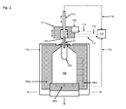
- FIG. 2 shows a side view of an exemplary embodiment of a treatment station in the form of a mold filling machine.
- the mold filling machine comprises a mold which is designed as a hollow mold, wherein the mold in the non-limiting embodiment shown here consists of two side parts 106a and 106b which can be moved or swiveled in the direction of the arrows by means of a multipart mold carrier 110 and a bottom part 106c which can be moved along the direction of the arrow.
- the mold After introducing a preform 103, the mold, as is well known, closed by moving together the mold parts 106a-c.
- the mold can be formed such that it closes pressure-tight with the preform 103 and thus forms a pressure-tight mold 106, by means of a media distributor 119, for example, a common rotary distributor for the plurality of treatment stations, via vacuum lines 118 and holes in the mold to support of the molding process can be evacuated to negative pressure.
- a media distributor 119 for example, a common rotary distributor for the plurality of treatment stations
- the hollow mold 106 in the interior of a vacuum container can be arranged, which can be evacuated via the vacuum lines 118.
- a vacuum container can then be arranged a pressure pad for holding the shell molds of the mold during the molding process, a support for the mold shells and / or connections for the temperature of the mold shells or the carrier.
- the vacuum container may be provided with at least two moving parts. In particular, these moving parts can be coupled to the drives of the support for the shell molds for insertion and removal.
- the carriers are in particular pivotally mounted on a shaft and book-like openable.
- the vacuum lines 118 represent a schematic embodiment of the connection lines described above, wherein the rotary distributor 119 may be connected, for example, to a loop as a central vacuum storage.
- the hollow mold 106 including the dead space of the connecting lines 118, optionally together with a vacuum chamber, thereby forms the vacuum region of a mold filling machine, the partial vacuum of which is to be recycled.
- a fluid nozzle of a valve block 111 can be placed on the mouth region 121 of the preform in a pressure-tight manner by means of a linear process, via the media and / or fill products into the preform or the plastic container to be molded with the desired one Pressure can be injected or -blasen.
- the valve block 111 is connected to the media distributor 119 via a feed line for a shaping fluid 114 and / or a feed line for a filling product 115.
- Controllable valves in the valve block 111 regulate the supply of molding fluid and / or filling product.
- the molding fluid may be a gaseous medium which is compressed, for example with a compressor 120, to the pressure required to form the preform.
- the molding fluid may also be a filling product.
- a suitable overpressure in the fluid can be generated. The same applies to the filling product in the supply line 115, wherein according to a development, a part of the molding of the container can be made with this filling product.
- the non-limiting form-filling machine shown here can furthermore have a stretching rod 113, which can be moved into the preform along the arrow direction shown, in order to stretch the preform to its desired length, which corresponds to the height of the finished plastic container.
- a stretching rod 113 can continue via a connection shown here as an extraction line 116 with the media distributor 119 already filled medium or filling product to escape again from the container or actively withdrawn.
- the stretch rod 113 can be used for filling and / or further molding of the container.
- the stretch rod 113 may have an opening and / or openings arranged along its longitudinal direction at its end facing the mold. The latter can be used in particular for effective mixing of hot and cold filling product.
- FIG. 2 shown arrangement, in particular the vacuum lines, only represents an exemplary development. A variety of alternative developments is conceivable, of which some are described explicitly below.
- FIG. 3 shows, for example, a side view of an exemplary embodiment of a treatment station in the form of a filling device.
- the now closed vacuum chamber 340 is evacuated to the desired target pressure and then filled product via the supply line 335 with filling valve into the container.
- the vacuum chamber 340 has three connecting lines, via which the desired target pressure in the vacuum chamber can be set.
- a first communication line 350 connects the vacuum chamber to another vacuum chamber (not shown) to provide pressure equalization in the formed pair of vacuum areas that comprise the respective vacuum chambers.
- a second connection line 360a may be provided to connect the vacuum chamber 340 to the main memory of a central vacuum accumulator as described above.
- a third connection line 360b may be provided to connect the vacuum chamber 340 to a recycling reservoir of the central vacuum reservoir. Further connecting lines, for example to further recycling stores and / or further vacuum chambers, are possible. Likewise, individual of the above-mentioned connecting lines can be omitted.
- the connecting lines 350, 360 a and 360 b are equipped with switchable valves (not shown), which preferably directly on the vacuum chamber 340, for example on the Wall of the vacuum chamber, are arranged.
- switchable valves (not shown)
- the valves can be individually and selectively opened and closed, so that targeted pressure equalization between the vacuum chamber 340 comprising the vacuum region and another vacuum region or the central vacuum reservoir can be produced.
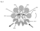
- FIG. 4 shows an exemplary embodiment of a device for vacuum recycling with pairs of vacuum areas and a central vacuum storage.
- each vacuum chamber comprises two connecting lines.
- the connecting lines 450 shown in broken lines each connect two vacuum chambers opposing each other along the circumference of the rotary machine, while the connecting lines 460 shown in solid lines connect the vacuum chambers to a central vacuum storage in the form of a main memory 470.
- An arrow indicates the direction of rotation of the vacuum chambers.
- a container to be treated is transferred to an open vacuum chamber 440-4, to which the ambient pressure is applied. After closing the vacuum chamber 440-2, it is partially evacuated via the connecting pipe 450 to the opposite vacuum chamber 440-1. Since a partial vacuum is still present in the vacuum chamber 440-1 even after the processing step has been carried out, the pressure in the vacuum chamber 440-2 to be evacuated, as described in detail above, can be reduced by pressure equalization with the vacuum chamber 440-1, so that the in the vacuum chamber 440-1 present partial vacuum can be partially recycled.
- the communication line 460 between the vacuum chamber 440-1 to be relieved and the main memory 470 of the central vacuum accumulator may be opened, since the pressure within the main accumulator 470 is below the equalizing pressure of the pair of vacuum chambers 440-1. 1 and 440-2. In this way, the partial vacuum present in the vacuum chamber 440-1 can be recycled more effectively in two steps than if only pressure equalization took place between the vacuum chambers 440-1 and 440-2.
- a pressure equalization between the then already vacuum-evacuated vacuum chamber 440-2 and the main memory 470 can take place by opening the corresponding connection line 460.
- the pressure in the main memory 470 is set so Main memory 470 connected to a vacuum pump (not shown) that is achieved by the pressure equalization of the desired target pressure in the vacuum chamber 440-2.
- the now partially relieved vacuum chamber 440-3 is then opened to remove the treated container, as indicated by the arrow in the figure.
- the vacuum chambers are each connected to the opposite vacuum chamber, so that separate pairs of vacuum chambers are formed, which are indirectly in communication with the main memory 470 only via their connecting lines 460.
- each vacuum chamber is connected to more than one further vacuum chamber in order to form groups of vacuum chambers.
- the pair does not necessarily have to consist of opposing vacuum chambers, as long as a vacuum chamber to be relieved can always be connected to a vacuum chamber to be evacuated.
- the main memory 470 may be arranged in particular symmetrically with respect to the vacuum chambers, so that the respective connecting lines 460 are the same length.
- FIG. 5 shows an alternative embodiment of a vacuum recycling apparatus having a main memory 570 and a recycling memory 580 as part of the central vacuum storage.
- main memory 570 and a recycling memory 580 as part of the central vacuum storage.
- no connecting lines between the vacuum chambers are provided. It is understood, however, that the embodiment shown, as described above, can be supplemented by such connecting lines for forming pairs of vacuum chambers.
- the central vacuum storage comprises a main storage 570 and a recycling storage 580.
- the main storage 570 and the recycling storage 580 are interconnected by a connection line for controlled pressure equalization (not shown), via which the pressure in the recycling storage 580 can be corrected.
- a series of recycling memories connected in series, the first recycling memory of which is connected to the main memory 570. Accordingly, there are more connecting lines between the recycling storage and the vacuum chambers.
- a series of recycling stores can store a cascade of decreasing pressures in order to allow the most efficient possible evacuation of the vacuum chamber 440-2 to be evacuated.
- a container to be treated is introduced into the open vacuum chamber 440-4, which is then closed.
- the now closed vacuum chamber 440-2 is partially evacuated via a first pressure equalization via a connecting line 560b shown with a dashed line with the recycling storage 580, since according to the invention a higher pressure in the recycling storage 580 than in the main memory 570.
- the partially evacuated vacuum chamber 440-2 on a connecting line 560a shown by a solid line is evacuated to the main memory 570 to the target pressure, and a vacuum pump connected to the main memory may be used.
- the evacuated vacuum chamber 440-1 is connected to main memory 570 via connecting line 560a to partially recycle the vacuum present in the vacuum chamber in the main memory, which is at a lower pressure than in the recycling store 580.
- the already partially relieved vacuum chamber 440-1 is connected via the connecting line 560b with the recycling storage 580 to recycle another part of the partial vacuum.
- the vacuum chamber 440-3 is opened to remove the treated container.
- the illustrated developments allow the partial recycling of a vacuum chamber to be relieved by partially relieving the pressure by equalizing the pressure with a central vacuum accumulator and / or a vacuum chamber to be evacuated.
- the energy requirement of a vacuum pump, which finally evacuates the vacuum chamber to be evacuated to the target pressure can be reduced.
- the recovery of the Vakuumpump essence can be improved, in particular, a large volume ratio between the vacuum reservoir and vacuum chamber is advantageous.
- the valves on the vacuum chambers the volume of required connection lines can be almost completely added to the storage volume.
- a loop can elegantly allow a symmetrical distribution of the volumes of the connecting lines.
Priority Applications (3)
| Application Number | Priority Date | Filing Date | Title |
|---|---|---|---|
| EP14181649.6A EP2987604B1 (fr) | 2014-08-20 | 2014-08-20 | Dispositif et procédé de recyclage à vide dans une installation de traitement de récipient |
| US14/826,521 US20160053777A1 (en) | 2014-08-20 | 2015-08-14 | Device and process for vacuum recycling in a container treatment unit |
| CN201510512330.3A CN105383041B (zh) | 2014-08-20 | 2015-08-19 | 在容器处理单元中真空再循环用的装置和方法 |
Applications Claiming Priority (1)
| Application Number | Priority Date | Filing Date | Title |
|---|---|---|---|
| EP14181649.6A EP2987604B1 (fr) | 2014-08-20 | 2014-08-20 | Dispositif et procédé de recyclage à vide dans une installation de traitement de récipient |
Publications (2)
| Publication Number | Publication Date |
|---|---|
| EP2987604A1 true EP2987604A1 (fr) | 2016-02-24 |
| EP2987604B1 EP2987604B1 (fr) | 2016-11-16 |
Family
ID=51389980
Family Applications (1)
| Application Number | Title | Priority Date | Filing Date |
|---|---|---|---|
| EP14181649.6A Active EP2987604B1 (fr) | 2014-08-20 | 2014-08-20 | Dispositif et procédé de recyclage à vide dans une installation de traitement de récipient |
Country Status (3)
| Country | Link |
|---|---|
| US (1) | US20160053777A1 (fr) |
| EP (1) | EP2987604B1 (fr) |
| CN (1) | CN105383041B (fr) |
Families Citing this family (4)
| Publication number | Priority date | Publication date | Assignee | Title |
|---|---|---|---|---|
| WO2018207787A1 (fr) * | 2017-05-10 | 2018-11-15 | 大日本印刷株式会社 | Machine de remplissage aseptique et procédé de remplissage aseptique |
| JP7428464B2 (ja) * | 2017-05-10 | 2024-02-06 | 大日本印刷株式会社 | 無菌充填機及び無菌充填方法 |
| JP6940807B2 (ja) * | 2017-05-17 | 2021-09-29 | 大日本印刷株式会社 | 無菌充填機及び無菌充填方法 |
| IT202200002438A1 (it) * | 2022-02-10 | 2023-08-10 | Siapi S R L | Metodo e impianto di soffiaggio di una preforma |
Citations (5)
| Publication number | Priority date | Publication date | Assignee | Title |
|---|---|---|---|---|
| DE3111925A1 (de) * | 1981-03-26 | 1982-10-07 | Robert Bosch Gmbh, 7000 Stuttgart | Verfahren und vorrichtung zum einsparen von druckluft, insbesondere bei thermoformmaschinen |
| EP0622301A1 (fr) * | 1993-04-29 | 1994-11-02 | Rudolf Christoph Bilz | Appareil d'évacuation |
| EP1529620B1 (fr) | 2003-11-06 | 2009-02-25 | Nestlé Waters Management & Technology | Procédé de fabrication de contenants en résine polyester |
| US20110031659A1 (en) | 2005-03-15 | 2011-02-10 | Graeme Warner | Stretch Blow Moulding Method and Apparatus |
| DE102013100513A1 (de) * | 2013-01-18 | 2014-07-24 | Krones Ag | Vorrichtung zum Expandieren von Kunststoffvorformlingen mit höhenversetzter Anordnung von Ventilen |
Family Cites Families (16)
| Publication number | Priority date | Publication date | Assignee | Title |
|---|---|---|---|---|
| US4488863A (en) * | 1981-02-23 | 1984-12-18 | The Continental Group, Inc. | Recycling of blow air |
| US4578928A (en) * | 1983-07-06 | 1986-04-01 | Acraloc Corporation | High speed evacuation chamber packaging machine and method |
| JPS62182014A (ja) * | 1986-01-30 | 1987-08-10 | 株式会社 古川製作所 | 真空包装装置 |
| US4843796A (en) * | 1988-03-22 | 1989-07-04 | Ecs Corporation | Method and apparatus for vacuum packaging |
| BE1004647A3 (fr) * | 1991-02-20 | 1993-01-05 | Solvay | Procede pour realiser, par moulage par soufflage, des corps creux en matiere thermoplastique presentant une impermeabilite aux gaz amelioree. |
| TW289008B (en) * | 1995-07-18 | 1996-10-21 | A K Tech Lab Inc | Air operation method and device for an extention blow forming machine |
| JPH0957840A (ja) * | 1995-08-24 | 1997-03-04 | Denki Kagaku Kogyo Kk | 中空容器の製造方法 |
| FR2766406B1 (fr) * | 1997-07-25 | 1999-09-17 | Sidel Sa | Procede et installation de fabrication de recipients par soufflage d'ebauches en materiau thermoplastique |
| DE102004014653B4 (de) * | 2004-03-25 | 2022-10-20 | Krones Aktiengesellschaft | Verfahren und Vorrichtung zum Herstellen eines insbesondere wärmebeständigen Hohlkörpers |
| DE102004041973B3 (de) * | 2004-08-31 | 2006-01-19 | Krones Ag | Luftrecycling im Blasformprozess |
| DE102004044260A1 (de) * | 2004-09-14 | 2006-04-06 | Sig Technology Ltd. | Verfahren und Vorrichtung zur Blasformung von Behältern |
| US20080191394A1 (en) * | 2007-02-09 | 2008-08-14 | Ebac Limited | Blow moulding apparatus and method |
| DE102009041013A1 (de) * | 2009-09-10 | 2011-03-24 | Krones Ag | Verfahren und Vorrichtung zum Blasformen von Behältern |
| US8828308B2 (en) * | 2010-09-13 | 2014-09-09 | Amcor Limited | Hydroblow preform design |
| DE102011005189A1 (de) * | 2011-03-07 | 2012-09-13 | Krones Aktiengesellschaft | Verfahren und Vorrichtung zum Recyceln von Druckgas |
| DE102013101775A1 (de) * | 2013-02-22 | 2014-08-28 | Khs Gmbh | Verfahren und Vorrichtung zur Herstellung und Füllen von Behältern |
-
2014
- 2014-08-20 EP EP14181649.6A patent/EP2987604B1/fr active Active
-
2015
- 2015-08-14 US US14/826,521 patent/US20160053777A1/en not_active Abandoned
- 2015-08-19 CN CN201510512330.3A patent/CN105383041B/zh active Active
Patent Citations (5)
| Publication number | Priority date | Publication date | Assignee | Title |
|---|---|---|---|---|
| DE3111925A1 (de) * | 1981-03-26 | 1982-10-07 | Robert Bosch Gmbh, 7000 Stuttgart | Verfahren und vorrichtung zum einsparen von druckluft, insbesondere bei thermoformmaschinen |
| EP0622301A1 (fr) * | 1993-04-29 | 1994-11-02 | Rudolf Christoph Bilz | Appareil d'évacuation |
| EP1529620B1 (fr) | 2003-11-06 | 2009-02-25 | Nestlé Waters Management & Technology | Procédé de fabrication de contenants en résine polyester |
| US20110031659A1 (en) | 2005-03-15 | 2011-02-10 | Graeme Warner | Stretch Blow Moulding Method and Apparatus |
| DE102013100513A1 (de) * | 2013-01-18 | 2014-07-24 | Krones Ag | Vorrichtung zum Expandieren von Kunststoffvorformlingen mit höhenversetzter Anordnung von Ventilen |
Also Published As
| Publication number | Publication date |
|---|---|
| CN105383041B (zh) | 2017-09-12 |
| EP2987604B1 (fr) | 2016-11-16 |
| CN105383041A (zh) | 2016-03-09 |
| US20160053777A1 (en) | 2016-02-25 |
Similar Documents
| Publication | Publication Date | Title |
|---|---|---|
| EP2930138B1 (fr) | Dispositif et procédé de fabrication d'une bouteille en plastique et de son remplissage d'un produit de remplissage | |
| EP2269803B1 (fr) | Procédé de changement d'outillage d'une souffleuse et souffleuse | |
| EP2958732B1 (fr) | Procédé et dispositif de fabrication et de remplissage de contenants | |
| EP2313245B1 (fr) | Dispositif et procédé pour façonner des préformes en plastique pourvu d'une salle stérile | |
| EP2987604B1 (fr) | Dispositif et procédé de recyclage à vide dans une installation de traitement de récipient | |
| DE2825866A1 (de) | Verfahren und vorrichtung zur herstellung von molekular orientierten kunststoff-flaschen | |
| EP2522485B1 (fr) | Machine et procédé de formage par soufflage aseptique avec évacuation stérile de l'air, ainsi que moule de soufflage | |
| EP2495089B1 (fr) | Machine de formage par soufflage dotée d'une chambre stérile chauffée et procédé | |
| EP2537662B1 (fr) | Dispositif et procédé de transformation d'ébauches en matière synthétique pour devenir des conteneurs en plastique avec mouvements de tige d'étirage étanches | |
| EP2848385A1 (fr) | Dispositif et procédé destinés au soufflage d'ébauches en plastique avec récupération d'air de soufflage | |
| EP2958805A1 (fr) | Procédé et dispositif de fabrication et de remplissage de récipients | |
| EP2987607B1 (fr) | Procédé de moulage et remplissage | |
| EP2113368B1 (fr) | Dispositif de formage par soufflage | |
| EP2848387B1 (fr) | Machine de moulage par soufflage avec une valve de soufflage pneumatique, et méthode de mise en oeuvre d'une telle machine. | |
| DE102011012751B4 (de) | Verfahren sowie Anlage zu Herstellung von mit einem flüssigen Füllgut gefüllten Behältern | |
| DE102012106916A1 (de) | Vorrichtung und Verfahren zum Umformen von Kunststoffvorformlingen mit getrennten Strömungswegen für Blasluft und Steuerluft | |
| DE102011102056A1 (de) | Verfahren sowie Vorrichtung zum Herstellen von gefüllten Behältern aus Vorformlingen | |
| DE202013008055U1 (de) | Vorrichtung zum Umformen von Kunststoffvorformlingen mit Reinraum | |
| EP2987606B1 (fr) | Procédé de démoulage et de remplissage de récipient et remplisseuse de moule | |
| EP2987610B1 (fr) | Remplisseuse de moule destinée à fabriquer et à remplir des récipients en plastique par recyclage de CO2 | |
| EP2176053A2 (fr) | Dispositif de soufflage de récipients | |
| EP2987619A1 (fr) | Remplisseuse de moule et procédé de démoulage et de remplissage de récipients | |
| DE102012111348A1 (de) | Streckblasverfahren sowie Streckblasmaschine | |
| EP2987609A1 (fr) | Remplisseuse de moule dotée d'un système de nettoyage et procédé | |
| EP2987617B1 (fr) | Bloc de soupapes pour une station de traitement d'une machine de souflage et remplissage et machine de souflage et remplissage dotée d'un bloc de soupapes |
Legal Events
| Date | Code | Title | Description |
|---|---|---|---|
| PUAI | Public reference made under article 153(3) epc to a published international application that has entered the european phase |
Free format text: ORIGINAL CODE: 0009012 |
|
| 17P | Request for examination filed |
Effective date: 20150427 |
|
| AK | Designated contracting states |
Kind code of ref document: A1 Designated state(s): AL AT BE BG CH CY CZ DE DK EE ES FI FR GB GR HR HU IE IS IT LI LT LU LV MC MK MT NL NO PL PT RO RS SE SI SK SM TR |
|
| AX | Request for extension of the european patent |
Extension state: BA ME |
|
| GRAP | Despatch of communication of intention to grant a patent |
Free format text: ORIGINAL CODE: EPIDOSNIGR1 |
|
| RIC1 | Information provided on ipc code assigned before grant |
Ipc: B29C 49/42 20060101AFI20160606BHEP |
|
| INTG | Intention to grant announced |
Effective date: 20160621 |
|
| GRAS | Grant fee paid |
Free format text: ORIGINAL CODE: EPIDOSNIGR3 |
|
| GRAA | (expected) grant |
Free format text: ORIGINAL CODE: 0009210 |
|
| AK | Designated contracting states |
Kind code of ref document: B1 Designated state(s): AL AT BE BG CH CY CZ DE DK EE ES FI FR GB GR HR HU IE IS IT LI LT LU LV MC MK MT NL NO PL PT RO RS SE SI SK SM TR |
|
| REG | Reference to a national code |
Ref country code: GB Ref legal event code: FG4D Free format text: NOT ENGLISH |
|
| REG | Reference to a national code |
Ref country code: CH Ref legal event code: EP |
|
| REG | Reference to a national code |
Ref country code: IE Ref legal event code: FG4D Free format text: LANGUAGE OF EP DOCUMENT: GERMAN |
|
| REG | Reference to a national code |
Ref country code: AT Ref legal event code: REF Ref document number: 845488 Country of ref document: AT Kind code of ref document: T Effective date: 20161215 |
|
| REG | Reference to a national code |
Ref country code: DE Ref legal event code: R096 Ref document number: 502014001971 Country of ref document: DE |
|
| PG25 | Lapsed in a contracting state [announced via postgrant information from national office to epo] |
Ref country code: LV Free format text: LAPSE BECAUSE OF FAILURE TO SUBMIT A TRANSLATION OF THE DESCRIPTION OR TO PAY THE FEE WITHIN THE PRESCRIBED TIME-LIMIT Effective date: 20161116 |
|
| REG | Reference to a national code |
Ref country code: NL Ref legal event code: MP Effective date: 20161116 |
|
| REG | Reference to a national code |
Ref country code: LT Ref legal event code: MG4D |
|
| PG25 | Lapsed in a contracting state [announced via postgrant information from national office to epo] |
Ref country code: SE Free format text: LAPSE BECAUSE OF FAILURE TO SUBMIT A TRANSLATION OF THE DESCRIPTION OR TO PAY THE FEE WITHIN THE PRESCRIBED TIME-LIMIT Effective date: 20161116 Ref country code: NO Free format text: LAPSE BECAUSE OF FAILURE TO SUBMIT A TRANSLATION OF THE DESCRIPTION OR TO PAY THE FEE WITHIN THE PRESCRIBED TIME-LIMIT Effective date: 20170216 Ref country code: NL Free format text: LAPSE BECAUSE OF FAILURE TO SUBMIT A TRANSLATION OF THE DESCRIPTION OR TO PAY THE FEE WITHIN THE PRESCRIBED TIME-LIMIT Effective date: 20161116 Ref country code: GR Free format text: LAPSE BECAUSE OF FAILURE TO SUBMIT A TRANSLATION OF THE DESCRIPTION OR TO PAY THE FEE WITHIN THE PRESCRIBED TIME-LIMIT Effective date: 20170217 Ref country code: LT Free format text: LAPSE BECAUSE OF FAILURE TO SUBMIT A TRANSLATION OF THE DESCRIPTION OR TO PAY THE FEE WITHIN THE PRESCRIBED TIME-LIMIT Effective date: 20161116 |
|
| PG25 | Lapsed in a contracting state [announced via postgrant information from national office to epo] |
Ref country code: PL Free format text: LAPSE BECAUSE OF FAILURE TO SUBMIT A TRANSLATION OF THE DESCRIPTION OR TO PAY THE FEE WITHIN THE PRESCRIBED TIME-LIMIT Effective date: 20161116 Ref country code: PT Free format text: LAPSE BECAUSE OF FAILURE TO SUBMIT A TRANSLATION OF THE DESCRIPTION OR TO PAY THE FEE WITHIN THE PRESCRIBED TIME-LIMIT Effective date: 20170316 Ref country code: RS Free format text: LAPSE BECAUSE OF FAILURE TO SUBMIT A TRANSLATION OF THE DESCRIPTION OR TO PAY THE FEE WITHIN THE PRESCRIBED TIME-LIMIT Effective date: 20161116 Ref country code: FI Free format text: LAPSE BECAUSE OF FAILURE TO SUBMIT A TRANSLATION OF THE DESCRIPTION OR TO PAY THE FEE WITHIN THE PRESCRIBED TIME-LIMIT Effective date: 20161116 Ref country code: ES Free format text: LAPSE BECAUSE OF FAILURE TO SUBMIT A TRANSLATION OF THE DESCRIPTION OR TO PAY THE FEE WITHIN THE PRESCRIBED TIME-LIMIT Effective date: 20161116 Ref country code: HR Free format text: LAPSE BECAUSE OF FAILURE TO SUBMIT A TRANSLATION OF THE DESCRIPTION OR TO PAY THE FEE WITHIN THE PRESCRIBED TIME-LIMIT Effective date: 20161116 |
|
| REG | Reference to a national code |
Ref country code: FR Ref legal event code: PLFP Year of fee payment: 4 |
|
| PG25 | Lapsed in a contracting state [announced via postgrant information from national office to epo] |
Ref country code: SK Free format text: LAPSE BECAUSE OF FAILURE TO SUBMIT A TRANSLATION OF THE DESCRIPTION OR TO PAY THE FEE WITHIN THE PRESCRIBED TIME-LIMIT Effective date: 20161116 Ref country code: DK Free format text: LAPSE BECAUSE OF FAILURE TO SUBMIT A TRANSLATION OF THE DESCRIPTION OR TO PAY THE FEE WITHIN THE PRESCRIBED TIME-LIMIT Effective date: 20161116 Ref country code: CZ Free format text: LAPSE BECAUSE OF FAILURE TO SUBMIT A TRANSLATION OF THE DESCRIPTION OR TO PAY THE FEE WITHIN THE PRESCRIBED TIME-LIMIT Effective date: 20161116 Ref country code: RO Free format text: LAPSE BECAUSE OF FAILURE TO SUBMIT A TRANSLATION OF THE DESCRIPTION OR TO PAY THE FEE WITHIN THE PRESCRIBED TIME-LIMIT Effective date: 20161116 Ref country code: EE Free format text: LAPSE BECAUSE OF FAILURE TO SUBMIT A TRANSLATION OF THE DESCRIPTION OR TO PAY THE FEE WITHIN THE PRESCRIBED TIME-LIMIT Effective date: 20161116 |
|
| REG | Reference to a national code |
Ref country code: DE Ref legal event code: R097 Ref document number: 502014001971 Country of ref document: DE |
|
| PG25 | Lapsed in a contracting state [announced via postgrant information from national office to epo] |
Ref country code: SM Free format text: LAPSE BECAUSE OF FAILURE TO SUBMIT A TRANSLATION OF THE DESCRIPTION OR TO PAY THE FEE WITHIN THE PRESCRIBED TIME-LIMIT Effective date: 20161116 Ref country code: BG Free format text: LAPSE BECAUSE OF FAILURE TO SUBMIT A TRANSLATION OF THE DESCRIPTION OR TO PAY THE FEE WITHIN THE PRESCRIBED TIME-LIMIT Effective date: 20170216 |
|
| PLBE | No opposition filed within time limit |
Free format text: ORIGINAL CODE: 0009261 |
|
| STAA | Information on the status of an ep patent application or granted ep patent |
Free format text: STATUS: NO OPPOSITION FILED WITHIN TIME LIMIT |
|
| 26N | No opposition filed |
Effective date: 20170817 |
|
| PG25 | Lapsed in a contracting state [announced via postgrant information from national office to epo] |
Ref country code: SI Free format text: LAPSE BECAUSE OF FAILURE TO SUBMIT A TRANSLATION OF THE DESCRIPTION OR TO PAY THE FEE WITHIN THE PRESCRIBED TIME-LIMIT Effective date: 20161116 |
|
| REG | Reference to a national code |
Ref country code: CH Ref legal event code: PL |
|
| PG25 | Lapsed in a contracting state [announced via postgrant information from national office to epo] |
Ref country code: MC Free format text: LAPSE BECAUSE OF FAILURE TO SUBMIT A TRANSLATION OF THE DESCRIPTION OR TO PAY THE FEE WITHIN THE PRESCRIBED TIME-LIMIT Effective date: 20161116 |
|
| PG25 | Lapsed in a contracting state [announced via postgrant information from national office to epo] |
Ref country code: CH Free format text: LAPSE BECAUSE OF NON-PAYMENT OF DUE FEES Effective date: 20170831 Ref country code: LI Free format text: LAPSE BECAUSE OF NON-PAYMENT OF DUE FEES Effective date: 20170831 |
|
| REG | Reference to a national code |
Ref country code: IE Ref legal event code: MM4A |
|
| REG | Reference to a national code |
Ref country code: BE Ref legal event code: MM Effective date: 20170831 |
|
| PG25 | Lapsed in a contracting state [announced via postgrant information from national office to epo] |
Ref country code: LU Free format text: LAPSE BECAUSE OF NON-PAYMENT OF DUE FEES Effective date: 20170820 |
|
| REG | Reference to a national code |
Ref country code: FR Ref legal event code: PLFP Year of fee payment: 5 |
|
| PG25 | Lapsed in a contracting state [announced via postgrant information from national office to epo] |
Ref country code: IE Free format text: LAPSE BECAUSE OF NON-PAYMENT OF DUE FEES Effective date: 20170820 |
|
| PG25 | Lapsed in a contracting state [announced via postgrant information from national office to epo] |
Ref country code: BE Free format text: LAPSE BECAUSE OF NON-PAYMENT OF DUE FEES Effective date: 20170831 |
|
| PG25 | Lapsed in a contracting state [announced via postgrant information from national office to epo] |
Ref country code: MT Free format text: LAPSE BECAUSE OF FAILURE TO SUBMIT A TRANSLATION OF THE DESCRIPTION OR TO PAY THE FEE WITHIN THE PRESCRIBED TIME-LIMIT Effective date: 20161116 |
|
| GBPC | Gb: european patent ceased through non-payment of renewal fee |
Effective date: 20180820 |
|
| PG25 | Lapsed in a contracting state [announced via postgrant information from national office to epo] |
Ref country code: HU Free format text: LAPSE BECAUSE OF FAILURE TO SUBMIT A TRANSLATION OF THE DESCRIPTION OR TO PAY THE FEE WITHIN THE PRESCRIBED TIME-LIMIT; INVALID AB INITIO Effective date: 20140820 |
|
| PG25 | Lapsed in a contracting state [announced via postgrant information from national office to epo] |
Ref country code: CY Free format text: LAPSE BECAUSE OF FAILURE TO SUBMIT A TRANSLATION OF THE DESCRIPTION OR TO PAY THE FEE WITHIN THE PRESCRIBED TIME-LIMIT Effective date: 20161116 Ref country code: GB Free format text: LAPSE BECAUSE OF NON-PAYMENT OF DUE FEES Effective date: 20180820 |
|
| PG25 | Lapsed in a contracting state [announced via postgrant information from national office to epo] |
Ref country code: MK Free format text: LAPSE BECAUSE OF FAILURE TO SUBMIT A TRANSLATION OF THE DESCRIPTION OR TO PAY THE FEE WITHIN THE PRESCRIBED TIME-LIMIT Effective date: 20161116 |
|
| PG25 | Lapsed in a contracting state [announced via postgrant information from national office to epo] |
Ref country code: TR Free format text: LAPSE BECAUSE OF FAILURE TO SUBMIT A TRANSLATION OF THE DESCRIPTION OR TO PAY THE FEE WITHIN THE PRESCRIBED TIME-LIMIT Effective date: 20161116 |
|
| PG25 | Lapsed in a contracting state [announced via postgrant information from national office to epo] |
Ref country code: AL Free format text: LAPSE BECAUSE OF FAILURE TO SUBMIT A TRANSLATION OF THE DESCRIPTION OR TO PAY THE FEE WITHIN THE PRESCRIBED TIME-LIMIT Effective date: 20161116 Ref country code: IS Free format text: LAPSE BECAUSE OF FAILURE TO SUBMIT A TRANSLATION OF THE DESCRIPTION OR TO PAY THE FEE WITHIN THE PRESCRIBED TIME-LIMIT Effective date: 20170316 |
|
| REG | Reference to a national code |
Ref country code: AT Ref legal event code: MM01 Ref document number: 845488 Country of ref document: AT Kind code of ref document: T Effective date: 20190820 |
|
| PG25 | Lapsed in a contracting state [announced via postgrant information from national office to epo] |
Ref country code: AT Free format text: LAPSE BECAUSE OF NON-PAYMENT OF DUE FEES Effective date: 20190820 |
|
| P01 | Opt-out of the competence of the unified patent court (upc) registered |
Effective date: 20230523 |
|
| PGFP | Annual fee paid to national office [announced via postgrant information from national office to epo] |
Ref country code: IT Payment date: 20230711 Year of fee payment: 10 |
|
| PGFP | Annual fee paid to national office [announced via postgrant information from national office to epo] |
Ref country code: FR Payment date: 20230703 Year of fee payment: 10 Ref country code: DE Payment date: 20230703 Year of fee payment: 10 |