EP2987012B1 - Adapter zum anschliessen eines medizinischen lasers an einen flexiblen wellenleiter oder gelenkarm - Google Patents
Adapter zum anschliessen eines medizinischen lasers an einen flexiblen wellenleiter oder gelenkarm Download PDFInfo
- Publication number
- EP2987012B1 EP2987012B1 EP14722361.4A EP14722361A EP2987012B1 EP 2987012 B1 EP2987012 B1 EP 2987012B1 EP 14722361 A EP14722361 A EP 14722361A EP 2987012 B1 EP2987012 B1 EP 2987012B1
- Authority
- EP
- European Patent Office
- Prior art keywords
- adaptor
- output port
- main
- laser
- flexible
- Prior art date
- Legal status (The legal status is an assumption and is not a legal conclusion. Google has not performed a legal analysis and makes no representation as to the accuracy of the status listed.)
- Active
Links
Images






Classifications
-
- A—HUMAN NECESSITIES
- A61—MEDICAL OR VETERINARY SCIENCE; HYGIENE
- A61B—DIAGNOSIS; SURGERY; IDENTIFICATION
- A61B18/00—Surgical instruments, devices or methods for transferring non-mechanical forms of energy to or from the body
- A61B18/18—Surgical instruments, devices or methods for transferring non-mechanical forms of energy to or from the body by applying electromagnetic radiation, e.g. microwaves
- A61B18/20—Surgical instruments, devices or methods for transferring non-mechanical forms of energy to or from the body by applying electromagnetic radiation, e.g. microwaves using laser
-
- G—PHYSICS
- G02—OPTICS
- G02B—OPTICAL ELEMENTS, SYSTEMS OR APPARATUS
- G02B6/00—Light guides; Structural details of arrangements comprising light guides and other optical elements, e.g. couplings
- G02B6/24—Coupling light guides
- G02B6/26—Optical coupling means
- G02B6/35—Optical coupling means having switching means
- G02B6/351—Optical coupling means having switching means involving stationary waveguides with moving interposed optical elements
- G02B6/3512—Optical coupling means having switching means involving stationary waveguides with moving interposed optical elements the optical element being reflective, e.g. mirror
- G02B6/3514—Optical coupling means having switching means involving stationary waveguides with moving interposed optical elements the optical element being reflective, e.g. mirror the reflective optical element moving along a line so as to translate into and out of the beam path, i.e. across the beam path
-
- A—HUMAN NECESSITIES
- A61—MEDICAL OR VETERINARY SCIENCE; HYGIENE
- A61B—DIAGNOSIS; SURGERY; IDENTIFICATION
- A61B18/00—Surgical instruments, devices or methods for transferring non-mechanical forms of energy to or from the body
- A61B18/18—Surgical instruments, devices or methods for transferring non-mechanical forms of energy to or from the body by applying electromagnetic radiation, e.g. microwaves
- A61B18/20—Surgical instruments, devices or methods for transferring non-mechanical forms of energy to or from the body by applying electromagnetic radiation, e.g. microwaves using laser
- A61B18/201—Surgical instruments, devices or methods for transferring non-mechanical forms of energy to or from the body by applying electromagnetic radiation, e.g. microwaves using laser with beam delivery through a hollow tube, e.g. forming an articulated arm ; Hand-pieces therefor
-
- A—HUMAN NECESSITIES
- A61—MEDICAL OR VETERINARY SCIENCE; HYGIENE
- A61B—DIAGNOSIS; SURGERY; IDENTIFICATION
- A61B18/00—Surgical instruments, devices or methods for transferring non-mechanical forms of energy to or from the body
- A61B18/18—Surgical instruments, devices or methods for transferring non-mechanical forms of energy to or from the body by applying electromagnetic radiation, e.g. microwaves
- A61B18/20—Surgical instruments, devices or methods for transferring non-mechanical forms of energy to or from the body by applying electromagnetic radiation, e.g. microwaves using laser
- A61B18/203—Surgical instruments, devices or methods for transferring non-mechanical forms of energy to or from the body by applying electromagnetic radiation, e.g. microwaves using laser applying laser energy to the outside of the body
-
- G—PHYSICS
- G02—OPTICS
- G02B—OPTICAL ELEMENTS, SYSTEMS OR APPARATUS
- G02B6/00—Light guides; Structural details of arrangements comprising light guides and other optical elements, e.g. couplings
- G02B6/24—Coupling light guides
- G02B6/42—Coupling light guides with opto-electronic elements
- G02B6/4296—Coupling light guides with opto-electronic elements coupling with sources of high radiant energy, e.g. high power lasers, high temperature light sources
-
- A—HUMAN NECESSITIES
- A61—MEDICAL OR VETERINARY SCIENCE; HYGIENE
- A61B—DIAGNOSIS; SURGERY; IDENTIFICATION
- A61B18/00—Surgical instruments, devices or methods for transferring non-mechanical forms of energy to or from the body
- A61B2018/00005—Cooling or heating of the probe or tissue immediately surrounding the probe
- A61B2018/00011—Cooling or heating of the probe or tissue immediately surrounding the probe with fluids
- A61B2018/00017—Cooling or heating of the probe or tissue immediately surrounding the probe with fluids with gas
-
- A—HUMAN NECESSITIES
- A61—MEDICAL OR VETERINARY SCIENCE; HYGIENE
- A61B—DIAGNOSIS; SURGERY; IDENTIFICATION
- A61B18/00—Surgical instruments, devices or methods for transferring non-mechanical forms of energy to or from the body
- A61B2018/00053—Mechanical features of the instrument of device
- A61B2018/00172—Connectors and adapters therefor
-
- A—HUMAN NECESSITIES
- A61—MEDICAL OR VETERINARY SCIENCE; HYGIENE
- A61B—DIAGNOSIS; SURGERY; IDENTIFICATION
- A61B18/00—Surgical instruments, devices or methods for transferring non-mechanical forms of energy to or from the body
- A61B2018/00636—Sensing and controlling the application of energy
- A61B2018/00696—Controlled or regulated parameters
-
- A—HUMAN NECESSITIES
- A61—MEDICAL OR VETERINARY SCIENCE; HYGIENE
- A61B—DIAGNOSIS; SURGERY; IDENTIFICATION
- A61B18/00—Surgical instruments, devices or methods for transferring non-mechanical forms of energy to or from the body
- A61B2018/00636—Sensing and controlling the application of energy
- A61B2018/00696—Controlled or regulated parameters
- A61B2018/00744—Fluid flow
-
- A—HUMAN NECESSITIES
- A61—MEDICAL OR VETERINARY SCIENCE; HYGIENE
- A61B—DIAGNOSIS; SURGERY; IDENTIFICATION
- A61B18/00—Surgical instruments, devices or methods for transferring non-mechanical forms of energy to or from the body
- A61B18/18—Surgical instruments, devices or methods for transferring non-mechanical forms of energy to or from the body by applying electromagnetic radiation, e.g. microwaves
- A61B18/20—Surgical instruments, devices or methods for transferring non-mechanical forms of energy to or from the body by applying electromagnetic radiation, e.g. microwaves using laser
- A61B2018/2015—Miscellaneous features
- A61B2018/2025—Miscellaneous features with a pilot laser
-
- G—PHYSICS
- G02—OPTICS
- G02B—OPTICAL ELEMENTS, SYSTEMS OR APPARATUS
- G02B6/00—Light guides; Structural details of arrangements comprising light guides and other optical elements, e.g. couplings
- G02B6/24—Coupling light guides
- G02B6/42—Coupling light guides with opto-electronic elements
- G02B6/4292—Coupling light guides with opto-electronic elements the light guide being disconnectable from the opto-electronic element, e.g. mutually self aligning arrangements
Definitions
- This invention relates to an adaptor for a medical laser unit, a medical laser unit, a method of adapting a base unit for a medical laser unit, a control unit for a medical laser unit and a method of operating a medical laser unit.
- Lasers have found a number of applications in medical procedures. Using suitably focussed and powerful laser beams, tissues can be excised, ablated or cut with fine control and with reduced bleeding. Example treatments are excision and vaporisation of benign and cancerous growths and fibromas, and aesthetic treatments.
- a CO2 laser is used as the source of the beam producing light at a wavelength of 10.6 ⁇ m. Because this wavelength is not suitable for transmission through conventional optical fibres, where it would be absorbed by the silica, it is known to use either hollow flexible waveguides, or internally reflective articulated arms, to direct the beam to the site of operation.
- Adaptors or switching apparatus that connect a base medical laser unit to a plurality of output devices and which comprise switching devices for controlling the travel path of the laser beam and one or more guiding beams are known from the state of the art, for example as described in US 4 550 240 A , EP 0093 005 A2 or FR 2 570 509 . It is also known from the state of the art, for example from EP 2 169 435 A2 or US 2012/321259 to use hollow flexible waveguides to guide a main laser beam and a guide beam at the same time whereby the guide beam can be guided through optical fibers which are embedded in the cladding of the hollow wave guide.
- a dual port switching apparatus and a flexible waveguide having a hollow core (91) within a silica substrate (92) whereby the inner surfaces of the silica substrate (92) is coated with a reflective surface (93);
- the switching adaptor comprising a connection part for mounting to a base unit, an input beam port to receive a main laser beam from a base unit, a first output port for connection to a flexible wave guide, a second output port for connection to an articulated arm, and a switching element moveable between a first position and a second position to direct an input beam to one of the first output port and the second output port.
- the adaptor further comprises an auxiliary guide beam source, and a beam combiner to direct an auxiliary guide beam to the first output port.
- the invention is characterized in that the auxiliary guide beam source is actuated if a flexible waveguide is selected by a user and the auxiliary guide beam is controllable to be directed into the silica substrate of the hollow wave guide.
- the switching element may comprise a mirror.
- the mirror may be moveable in a linear direction between the first position and the second position.
- the adaptor may comprise a linear actuator operable to move the switching element between the first position and the second position.
- the input beam port may define an input beam path extending generally vertically, one of the first and second output ports may extend substantially vertically in line with the input beam path, and the other of the first output port and second output port may extend at an angle relative to the input beam path.
- the switching element In one of the first position and of the second position the switching element may extends into the input beam path, and in the other of the first position and second position, may be spaced from the input beam path.
- the adaptor may comprise a pressurized gas connection to allow supply of pressurized gas to the first output port.
- a medical laser unit comprising a base unit, the base unit comprising a main laser source and a base unit output port, and an adaptor according to the first aspect of the invention, the adaptor being mounted on the base unit such that the input beam port is connected to the base output beam port to receive the main beam from the main laser source.
- the main laser source may comprise a CO 2 laser to provide the main beam.
- the base unit may comprise a main guide beam source and alignment optics wherein the main laser guide beam may be aligned with the CO2 laser beam.
- the apparatus may comprise a control unit operable to control the main laser source.
- the medical laser unit may have a user input device to receive user instructions and transmit instructions to the control unit.
- the control unit is may be operable to control the switching element.
- the medical laser unit may be operable to detect if a flexible wave guide is connected to the first output port.
- control unit may be operable to control the switching element to direct the CO s laser beam to the first output port, and control the auxiliary guide beam source.
- the medical laser unit may comprised a pressurised gas source and a pressurised gas controller, the control unit being operable to control the pressurised gas controller to direct cooling fluid to one of the first output port and an articulated arm.
- a method of adapting a medical laser apparatus comprising the step of providing an adaptor according to the first aspect of the invention, and mounting the adaptor on the base unit such that the input beam port is aligned with the laser beam port.
- the method may comprise the step of connecting the control unit to the switching element such that the control unit is operable to move the switching element between the first position and the second position.
- the method may comprise the step of connecting the control unit to the auxiliary guide beam source such that the control unit is operable to control the auxiliary guide beam.
- a control unit for a medical laser unit comprising a main laser to generate a main beam
- the medical laser unit having an adaptor comprising a first output port, a second output port and a switching element, the control unit being operable to receive an operator input and move the switching element between a first position in which the main beam is directed to the first output port and a second position in which the main beam is directed to the second output port.
- a method of operating a medical laser unit comprising operating a main laser to generate a main beam, and operating a switching element to move the switching element between a first position in which the main beam is directed to a first output port and a second position in which the main beam is directed to a second output port.
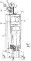
- the medical laser unit comprises a base unit 11 and an adaptor 12, which will be described hereafter in more detail.
- the base unit 11 comprises a main laser source (not shown), in the present example comprising a CO 2 laser, to generate a main laser beam with an output wavelength of 10.6 ⁇ m.
- a main laser source (not shown)
- a main guide laser (not shown) is also mounted in the base unit 11 to produce a visual main guide beam.
- Suitable beam combination and collimation optics are provided such that the base unit 11 outputs a main beam comprising the 10.6 ⁇ m beam and the main guide beam such that both beams are collimated and co-propagating.
- the base unit 11 further comprises a control unit shown in dashed outline at 13 and a control screen 13a which is operable to display operating information received from a control unit and to receive operator input to the control unit to control the laser output of the medical laser unit 10.
- the main beam and main guide beam are transmitted to the adaptor 12.
- the adaptor 12 has a first output port 14, for connection to a hollow waveguide, and a second output port 15 for connection to an internally reflective articulated arm 16.
- the adaptor 12 has a switching element, described below, which is controllable by the control unit 13 to direct the received main beam to one of the first output port 14 and second output port 15 as directed by an operator.
- control unit 13 may be connected to the control unit 13 such that they operate as a single controller, preferably in a manner transparent to the operator.
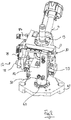
- the adaptor 12 will now be described in more detail with reference to figures 2 to 8 .
- the adaptor 12 comprises an opto-mechanical chassis generally shown at 20. This is a solid, rigid body which serves as a reference surface with fixed location stops onto which other components can be mounted.
- the opto-mechanical chassis comprises a main body 21 with a number of ports and recesses defined therein.
- the main body 21 is milled from aluminium to provide suitable rigidity, coefficient of thermal expansion and robustness.
- the surfaces are also finished, for example by anodising, to produce a protective surface which has a matt texture to diffuse potentially hazardous laser reflections.
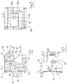
- input beam path 22 extends vertically from a lower part of the body 21.
- First output beam path 23 and second output beam path 24 lead to the first output port 14and second output port 15 respectively.
- First output beam path 23 is co-planar with the input beam path 22 and second output beam path 24, and is inclined at an oblique angle relative to the input beam path 22.
- the second output beam path 24 is co-linear with input beam path 22.
- the rigid body 21 has an output support part best shown at 25, which has a third output beam path 26 extending therethrough which is co-linear with the first output beam path 24.
- the support part 25 has an inclined connection face 27 which is perpendicular to the third output beam path 26 and provided with mounting points 28.
- Channel 29 extends in a linear manner into the main body 21 and has an angled inner face 30.
- Input beam path 22 and first beam path 23 have respective openings 22a, 23a in the angled surface 30, and the input, first and second beam paths 22, 23, 24 converge at point A within channel 29.
- the opto-mechanical chassis 21 comprises an auxiliary guide laser support 31 extending alongside the support part 25.
- the support part 25 has an inclined rear surface 32 to support an auxiliary guide beam combiner as discussed in more detail below and a transversely extending auxiliary guide beam path 32a extending towards a corresponding board in the auxiliary guide beam support arm 31.
- connection points 34 for connection to a beam combiner comprising the second output port 15 to direct the beam to an articulated arm 16.
- the opto-mechanical chassis 20 further comprises a vertical support 40, on which the main body 21 is supported.
- the vertical support 40 comprises a generally cylindrical body 41 defining an input beam port.
- An upper flange 42 engages a lower surface 35 of the body 21 and comprises a plurality of apertures 43 through which bolts 44 may pass to be received in threaded apertures (not shown) in the body 21.
- the vertical support 40 comprises an outwardly extending flange 45 with apertures 46 therein to enable the vertical support 40 to be connected to an optical bench surface 47 provided at the upper surface of the base unit 11.
- the control switch comprises a mirror mount 51 best shown in Fig. 9 which has a vertical support plate 52.
- the vertical support plate 52 comprises a mirror support arm 53 which is dimensioned to be received in channel 29.
- a mirror support plate 54 which is inclined relative to the vertical support plate 52.
- the mirror support plate 54 has a circular aperture 55 in which is received a plane mirror 56, the reflective surface of the mirror being directed downwardly and to the left as shown in Fig. 9 .
- a plane mirror it will be apparent that a curved mirror may be used if desirable, for example for focussing or beam conditioning purposes.
- aperture 55 has an inwardly directed lip 57.
- Three recesses 58 are located within the lip 57 which receive bearing balls 59, the bearing balls 59 defining a correctly aligned surface.
- the mirror 56 when in position is supported by these bearing balls 59.
- a retaining ring 60 is held in place by screws 61 against the back of the mirror 56.
- the opto-mechanical chassis 20 is provided with horizontally extending guide rails 70, 71 disposed above and below the channel 29.
- Fig. 10 shows lower guide rail 71 in position and upper guide rail 70 in the correct orientation for connection to the chassis 20.
- Upper guide block 70a is slidably mounted on the upper guide rail 70
- lower guide blocks 71a, 71a are slidably mounted on the lower guide rail 71.
- Vertical support plate 51 is connected to the guide blocks 70a, 71a, 71b such that the mirror assembly 50 is moveable lengthways of the channel 29.
- a linear actuator comprising a stepper motor 72 connected to a threaded rod 73 extending through a suitable threaded nut 77.
- Driving the stepper motor 72 causes the rod 73 to rotate and hence causes linear movement of the nut 77 and mirror assembly 50.
- the connection between the mirror assembly 50 and nut 77 preferably comprises a spring or flexible element to provide a degree of freedom between the mount and actuator.
- each step of the stepper motor moves the mirror assembly by 13 ⁇ m.
- Screw 76 has a distal ball end located to provide an end stop for the mirror assembly 50.
- the mirror assembly 50 is thus movable by the linear actuator between first and second positions.
- the mirror 56 extends between the input beam path 22 and second input beam path 24, such that the main beam is reflected into first beam path 23.
- the mirror surface passes through point A in Fig.4 .
- the mirror assembly is offset from the beam paths 22, 23, 24 such that the main passes from the input beam path 22 to the second output beam path 24.
- optical sensors 74, 75 are provided to confirm when the mirror assembly 50 is in the first position or second position.
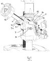
- Fig. 11 is a perspective view of the opto-mechanical chassis 21 showing the output port 14 and the auxiliary guide beam support 31.
- the first output port 14 comprises a cylindrical element 80 with a flange 81 at one end which is connected to the angled surface 27 of the opto-mechanical chassis 21 by bolts 81a received in threaded bores 28.
- a wave guide connection port 82 is mounted at the opposite end, protected by a lid 83.
- the auxiliary guide beam source is shown at 84 comprising a red laser diode with its associated electronics mounted in a single element.
- the auxiliary guide beam beam 84 is mounted on a support plate 85 which is adjustably connected to the support 31 by adjustable bolts 86.
- the auxiliary guide beam source 84 is directed at a beam combiner comprising an angled mirror 88 supported at the inclined rear surface 32 such that it is set at approximately 45° to the cylindrical part 80 and the auxiliary guide beam source 84.
- the angled mirror 88 is positioned such that the aiming beam is directed into the first output port 14 and the main laser beam, when directed through first output beam path 24, passes through the mirror 88 substantially undeflected and into third output beam path 26. It will be apparent that the beam acts to combine the main laser beam and auxiliary guide beam when the first output port 14 is in use.
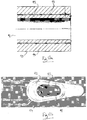
- the flexible wave guide 90 has a hollow core 91 within a silica substrate 92.
- the inner surfaces of the silicate substrate 92 are coated with a reflective surface 93, in the present example an interface film of silver deposited on the inner surface of the silicate substrate, and then a silver iodide coat deposited on the silver interface film.
- the silica substrate 92 is surrounded by a protective polymer coating 94.
- a guide beam is provided by directing the auxiliary guide beam into the silica substrate 92.
- the bolts 86 are adjusted such that the aiming beam is offset from the main beam as illustrated in Fig. 14a .
- the end of the flexible wave guide is held in a connector 95, and the beams are aligned in such that the main beam 96 is directed into the hollow core 91 and the auxiliary guide beam 97 is offset from the main beam 96 and enters the silica substrate 92.
- the alignment can be carried using an apparatus such as that shown in Fig.
- a dummy fibre holder 98 having the same dimensions as the waveguide holder 95.
- a conventional optical fibre 99 is held within the dummy fibre holder 98 such that the end 99a of the fibre 99 is at the same offset position as the silica cladding 92 of the flexible wave guide 90.
- a photodetector 100 is used to measure the light coupled into the alignment fibre 99. Accordingly, the bolts 86 can be adjusted to vary the direction of the auxiliary guide beam 97 to maximise the signal at the photodetector unit 100 to confirm that the auxiliary guide beam is correctly aligned.
- a cooling fluid system is provided, in the present example a pneumatic cooling air system.
- a suitable cooling system is shown diagrammatically in Fig. 12 .
- the base unit is diagrammatically illustrated at 11 and a pneumatic control apparatus is shown at 110.
- a distributor is shown at 111 which can receive pressurized from an internal compressor 112 provided within the base unit 11, or from an external source 113, which may be an external tank or an external pneumatic supply system.
- the distributor 111 is under the control of the control unit in the base unit 11.
- a first pneumatic connection 114 leads from the distributor 111 to an air chamber 115 located in flow communication with the wave guide connection part 82.
- a second pneumatic connection 116 is connectible to external flexible air tubes shown diagrammatically at 117 which extend along an outside surface of the articulated arm 16 and direct air towards an accessory or control element at the distal end of the articulated arm 16, for example to be connected to an air inlet of the accessory.
- the supply of cooling fluid amongst other advantages helps to cool the flexible wave guide, when working at high energies, and also blows smoke or debris away from the operating point of the laser. Where a higher air flow is required, particularly for using a flexible wave guide at high energies, the internal compressor 112 may not be sufficient and the connection to an external source 113 is desirable.
- suitably filtered and dry compressed air is used, it will be apparent that any other suitable gas or gas mixture may be used.
- a medical laser unit 10 may be adapted by removing pre-existing articulated arm or flexible wave guide connection, and attaching an adaptor 15 to an optical bench part of the base unit 11 as described herein.
- the method of adapting the medical laser unit may also include connecting the optical wave guide connector part 82 to the control unit, and connecting the auxiliary guide beam laser 80 to the control unit.
- the actuator is similarly connected to the control unit.
- the adaptor 15 is provided with a dedicated controller 120 mounted on the optical chassis 21, and the auxiliary controller 120 is operable to transmit and receive information to the controller, and control the linear actuator and auxiliary guide beam laser in response to instructions from the controller.
- the pneumatic distributor 111 may be controlled by the auxiliary controller 120 or entirely controlled by the main controller.
- the controller may detect the presence of an optical wave guide, or be informed of the presence of the optical wave guide by the auxiliary controller 120 and present options to the operator on the screen. If the operator selects the flexible wave guide, then the auxiliary guide beam laser is actuated, and the actuator is operated to move the switching apparatus to the first position.
- the main laser beam is directed to the first output port 14 and into the flexible wave guide, and the auxiliary guide beam is directed into the silica substrate of the flexible wave guide as discussed herein.
- the pneumatic distributor 111 is operated to supply air under pressure through the flexible wave guide as discussed above.
- the linear actuator is operated to move the mirror assembly to the second position. In this position, the main laser beam and the guide beam are unobstructed and pass through the input beam path, second beam path and are reflected within the articulated arm.
- the pneumatic distributor is operated to supply pressurized air to the articulated arm connection.
- the auxiliary guide beam laser is not activated as the auxiliary guide beam is not required.
- a medical laser unit may be provided as a new unit with an adaptor 12 already installed. If so, it will be apparent that auxiliary controller 120 may be omitted and the linear actuator, auxiliary guide beam laser and flexible wave guide detector may be directly connectible to and operated by the main control unit. When a medical laser unit is modified to have an adaptor 12, the software in the main control unit may be updated accordingly.
Landscapes
- Physics & Mathematics (AREA)
- Health & Medical Sciences (AREA)
- Optics & Photonics (AREA)
- Surgery (AREA)
- Life Sciences & Earth Sciences (AREA)
- General Physics & Mathematics (AREA)
- Biomedical Technology (AREA)
- Molecular Biology (AREA)
- Nuclear Medicine, Radiotherapy & Molecular Imaging (AREA)
- Engineering & Computer Science (AREA)
- Electromagnetism (AREA)
- Heart & Thoracic Surgery (AREA)
- Medical Informatics (AREA)
- Otolaryngology (AREA)
- Animal Behavior & Ethology (AREA)
- General Health & Medical Sciences (AREA)
- Public Health (AREA)
- Veterinary Medicine (AREA)
- Laser Surgery Devices (AREA)
- Radiation-Therapy Devices (AREA)
- Lasers (AREA)
Claims (16)
- Ein Dual-Anschluss-Schaltadapter (12) und ein flexibler Wellenleiter, wobei der flexible Wellenleiter (90) einen inneren Hohlraum (91) innerhalb eines Siliziumsubstrats (92) aufweist, wobei die innere (91) Oberflächen des Siliziumsubstrats (92) mit einer reflektierende Oberfläche (93) beschichtet ist; der Schaltadapter (12) ein Verbindungsteil zur Befestigung an einer Basiseinheit (11) umfasst,
einen Strahlen-Eingangs-Anschluss zum Empfangen eines Hauptlaserstrahls von einer Basiseinheit (11) umfasst, einen ersten Ausgangs-Anschluss (14) umfasst, der lösbar mit einem flexiblen hohlen Wellenleiter zur Leitung eines Hauptstrahls (96) in den inneren Hohlraum (91) des flexiblen Wellenleiters umfasst, einen zweiten Ausgangs-Anschluss (15) umfasst zur Verbindung mit einem gelenkig beweglichen Arm (16) und zum Leiten des Hauptstrahls in den gelenkig beweglichen ein Arm (16) und
ein Schaltelement (56) umfasst, das zwischen einer ersten Position und einer zweiten Position bewegbar ist, um einen Eingangsstrahl an den ersten Ausgangs-Anschluss (14) oder den zweiten Ausgangs-Anschluss (15) zu leiten, wobei der Adapter (12) ferner eine zusätzliche Leitstrahlen-Quelle (84) und einen Strahlen-Kombinierer umfasst, um einen zusätzlichen Leitstrahl zum ersten Ausgangsanschluss zu leiten,
dadurch gekennzeichnet, dass der zusätzlichen Leitstrahl (97) so steuerbar ist, dass er in das Silikon-Material des hohlen Wellenleiters (92) geleitet wird. - Ein Adapter (12) und ein flexibler hohler Wellenleiter nach Anspruch 1, wobei das Schaltelement (56) einen Spiegel umfasst.
- Ein Adapter (12) und ein flexibler hohler Wellenleiter nach Anspruch 2, wobei der Spiegel in einer linearen Richtung zwischen der ersten Position und der zweiten Position bewegbar ist.
- Ein Adapter (12) und ein flexibler hohler Wellenleiter nach Anspruch 3, umfassend ein lineares Stellglied, das zum Bewegen des Schaltelementes zwischen der ersten Position und der zweiten Position ausgebildet ist.
- Ein Adapter (12) und ein flexibler hohler Wellenleiter nach einem der vorstehenden Ansprüche, wobei der zusätzliche Leitstrahl so einstellbar ist, dass der zusätzliche Leitstrahl (97) in eine Hüllschicht des hohlen Wellenleiters geleitet wird.
- Ein Adapter (12) und ein flexibler hohler Wellenleiter nach einem der vorstehenden Ansprüche, wobei der Eingangs-Strahl-Anschluss einen Eingangs-Strahlengang definiert, der sich im Wesentlichen in vertikaler Richtung erstreckt, und wobei entweder der erste oder der zweite Ausgangs-Anschluss (14, 15) sich im Wesentlichen vertikal in einer Linie mit dem Eingangs-Strahlengang erstreckt und der andere Ausgangs-Anschluss sich unter einem Winkel bezogen auf den Eingangs-Strahlengang erstreckt.
- Ein Adapter (12) und ein flexibler hohler Wellenleiter nach Anspruch 6, wobei das Schaltelement entweder in einer ersten Position oder in einer zweiten Position in den Eingangs-Strahlengang hineinragt und in der anderen Position vom Eingangs-Strahlengang beabstandet ist.
- Ein Adapter (12) und ein flexibler hohler Wellenleiter nach einem der vorstehenden Ansprüche, umfassend einen Kühlflüssigkeits-Anschluss um Kühlmittel dem ersten Ausgangs-Anschluss zuzuführen.
- Medizinische Lasereinheit (10), umfassend eine Basiseinheit (11), die Basiseinheit, umfassend eine Laserquelle und einen Basiseinheit-Ausgangs-Anschluss, und einen Adapter (12) und einen flexiblen hohlen Wellenleiter nach einem der vorstehenden Ansprüche, wobei der Adapter auf der Basiseinheit (11) so montiert ist, dass der Strahlen-Eingangs-Anschluss mit dem Basis-Strahlen-Ausgangs-Anschluss verbunden ist, um den Hauptstrahl von der Hauptlaserquelle zu empfangen, wobei die Basiseinheit eine Hauptleitstrahlen-Quelle und Ausrichtung-Optik umfasst, mit der der Hauptleitstrahl nach dem Hauptstrahl ausgerichtet wird.
- Medizinische Lasereinheit (10) nach Anspruch 9, wobei die Hauptlaserquelle einen CO2-Laser umfasst, um den Hauptstrahl bereit zu stellen.
- Medizinische Lasereinheit (10) nach Anspruch 9 oder Anspruch 10, umfassend eine Steuereinheit (13), die zum Steuern der Hauptlaserquelle ausgebildet ist.
- Medizinische Lasereinheit (10) nach Anspruch 11 mit einem Benutzereingabegerät zum Empfangen von Benutzeranweisungen und Übertragen von Anweisungen an die Steuereinheit (13).
- Medizinische Lasereinheit nach Anspruch 11 oder Anspruch 12, wobei die Steuereinheit (13) ausgebildet ist, um das Schaltelement (56) zu steuern.
- Medizinische Lasereinheit nach einem der Ansprüche 9 bis 13, welche dazu ausgebildet ist, zu erkennen, ob ein flexibler Wellenleiter mit dem ersten Ausgangs-Anschluss (14) verbunden ist.
- Medizinische Lasereinheit nach Anspruch 14 in Verbindung mit Anspruch 10, wobei, wenn ein flexibler Wellenleiter erkannt wird, die Steuereinheit (13) dazu ausgebildet ist, das Schaltelement (56) so zu steuern, dass der CO2-Laserstrahl auf den ersten Ausgangs-Anschluss (14) gerichtet wird und die Hilfsleitstrahlquelle steuert.
- Medizinische Lasereinheit nach einem der Ansprüche 9 bis 15, umfassend eine Druckgasquelle und eine Druckgas-Steuerung, wobei die Steuereinheit zum Steuern der Druckgas-Steuerung ausgebildet ist, um das Kühlfluid entweder an den ersten Ausgangs-Anschluss (14) oder an einen gelenkig beweglichen Arm (16) zu leiten.
Priority Applications (1)
| Application Number | Priority Date | Filing Date | Title |
|---|---|---|---|
| EP19179392.6A EP3605173B1 (de) | 2013-04-15 | 2014-04-14 | Adapter zum anschliessen eines medizinischen lasers an einen flexiblen wellenleiter oder gelenkarm |
Applications Claiming Priority (2)
| Application Number | Priority Date | Filing Date | Title |
|---|---|---|---|
| GB1306832.5A GB2513123B (en) | 2013-04-15 | 2013-04-15 | Adaptor |
| PCT/IB2014/060704 WO2014170815A1 (en) | 2013-04-15 | 2014-04-14 | Adapter for connecting a medical laser to a flexible waveguide or an articulated arm |
Related Child Applications (1)
| Application Number | Title | Priority Date | Filing Date |
|---|---|---|---|
| EP19179392.6A Division EP3605173B1 (de) | 2013-04-15 | 2014-04-14 | Adapter zum anschliessen eines medizinischen lasers an einen flexiblen wellenleiter oder gelenkarm |
Publications (2)
| Publication Number | Publication Date |
|---|---|
| EP2987012A1 EP2987012A1 (de) | 2016-02-24 |
| EP2987012B1 true EP2987012B1 (de) | 2019-06-12 |
Family
ID=48537279
Family Applications (2)
| Application Number | Title | Priority Date | Filing Date |
|---|---|---|---|
| EP19179392.6A Active EP3605173B1 (de) | 2013-04-15 | 2014-04-14 | Adapter zum anschliessen eines medizinischen lasers an einen flexiblen wellenleiter oder gelenkarm |
| EP14722361.4A Active EP2987012B1 (de) | 2013-04-15 | 2014-04-14 | Adapter zum anschliessen eines medizinischen lasers an einen flexiblen wellenleiter oder gelenkarm |
Family Applications Before (1)
| Application Number | Title | Priority Date | Filing Date |
|---|---|---|---|
| EP19179392.6A Active EP3605173B1 (de) | 2013-04-15 | 2014-04-14 | Adapter zum anschliessen eines medizinischen lasers an einen flexiblen wellenleiter oder gelenkarm |
Country Status (6)
| Country | Link |
|---|---|
| US (4) | US10746936B2 (de) |
| EP (2) | EP3605173B1 (de) |
| CN (2) | CN105143939B (de) |
| GB (1) | GB2513123B (de) |
| IL (3) | IL300941B2 (de) |
| WO (1) | WO2014170815A1 (de) |
Families Citing this family (4)
| Publication number | Priority date | Publication date | Assignee | Title |
|---|---|---|---|---|
| GB2513123B (en) * | 2013-04-15 | 2015-12-02 | Lumenis Ltd | Adaptor |
| US10175445B2 (en) | 2014-10-20 | 2019-01-08 | Lumenis Ltd. | Apparatus and method for aligning light beams |
| ES2946276T3 (es) * | 2017-12-12 | 2023-07-14 | Alcon Inc | Fibra multinúcleo para una sonda láser multipunto |
| WO2022013144A1 (en) | 2020-07-14 | 2022-01-20 | El.En. S.P.A. | A laser equipment with a laser source and a beam deflector |
Family Cites Families (27)
| Publication number | Priority date | Publication date | Assignee | Title |
|---|---|---|---|---|
| DE3379322D1 (en) * | 1982-04-27 | 1989-04-13 | Sumitomo Electric Industries | Laser device |
| JPS5954488A (ja) * | 1982-09-21 | 1984-03-29 | Nippon Sekigaisen Kogyo Kk | レ−ザ照射装置 |
| US4532400A (en) * | 1982-10-01 | 1985-07-30 | Nippon Infrared Industries Co., Ltd. | Laser irradiating apparatus |
| FI843653A7 (fi) * | 1984-09-18 | 1986-03-19 | Lasertek Oy | Kopplingsenhet foer en laseranlaeggning. |
| JPH052114A (ja) * | 1991-06-24 | 1993-01-08 | Ebara Corp | 紫外レーザ光用合成樹脂製中空導波管 |
| US5729643A (en) * | 1996-04-05 | 1998-03-17 | Coherent, Inc. | Tapered composite optical fiber and method of making the same |
| US6331181B1 (en) * | 1998-12-08 | 2001-12-18 | Intuitive Surgical, Inc. | Surgical robotic tools, data architecture, and use |
| GB0415847D0 (en) * | 2004-07-15 | 2004-08-18 | Polatis Ltd | Four axis actuation |
| US20070147752A1 (en) * | 2005-06-10 | 2007-06-28 | Omniguide, Inc. | Photonic crystal fibers and systems using photonic crystal fibers |
| US10098781B2 (en) * | 2006-03-24 | 2018-10-16 | Topcon Medical Laser Systems Inc. | Multi-spot optical fiber endophotocoagulation probe |
| US20080043353A1 (en) * | 2006-06-30 | 2008-02-21 | Christopher Horvath | Apparatus and system for steering an optical beam |
| US20100074618A1 (en) * | 2006-08-03 | 2010-03-25 | Nabtesco Corporation | Optical path switching device |
| CN101933202B (zh) * | 2007-12-17 | 2013-05-29 | 奥兰若光电公司 | 激光发射器模块及装配的方法 |
| US7835065B2 (en) * | 2008-01-30 | 2010-11-16 | Corning Incorporated | Optical packages and methods for aligning optical packages |
| EP2600180A1 (de) * | 2008-05-09 | 2013-06-05 | Hewlett-Packard Development Company, L.P. | Optische Splittervorrichtung |
| CN106342258B (zh) * | 2008-09-02 | 2012-08-29 | 中国电子科技集团公司第二十七研究所 | 一种激光光路切换装置 |
| EP2169435A3 (de) * | 2008-09-26 | 2010-05-12 | Lumenis Ltd. | Wellenleiter mit Zielmechanismen |
| US7982935B2 (en) * | 2008-12-31 | 2011-07-19 | Yuri Grapov | Mirror positioning apparatus for use in beam switching |
| CN102804009A (zh) * | 2009-10-22 | 2012-11-28 | 耶路撒冷希伯来大学伊森姆研究发展公司 | 用于切换光通道的方法和系统 |
| US8625989B2 (en) * | 2011-01-21 | 2014-01-07 | Finisar Corporation | Multi-laser transmitter optical subassemblies for optoelectronic modules |
| JP2012239698A (ja) * | 2011-05-20 | 2012-12-10 | Akira Sasaki | 練習装置 |
| US20120321259A1 (en) * | 2011-06-14 | 2012-12-20 | Luke Lu | Light-transmittable composite tube |
| CN103997948B (zh) * | 2011-10-19 | 2016-06-01 | 艾里德克斯公司 | 栅格图案激光治疗及方法 |
| US10369051B2 (en) * | 2012-05-30 | 2019-08-06 | Ellex R&D Pty Ltd | Reflex coaxial illuminator |
| US20140121653A1 (en) * | 2012-10-31 | 2014-05-01 | Nidek Co., Ltd. | Ophthalmic laser treatment apparatus |
| CN203133335U (zh) * | 2013-03-13 | 2013-08-14 | 深圳新飞通光电子技术有限公司 | 四端口olt光收发一体模块 |
| GB2513123B (en) * | 2013-04-15 | 2015-12-02 | Lumenis Ltd | Adaptor |
-
2013
- 2013-04-15 GB GB1306832.5A patent/GB2513123B/en active Active
-
2014
- 2014-04-14 CN CN201480021115.7A patent/CN105143939B/zh active Active
- 2014-04-14 IL IL300941A patent/IL300941B2/en unknown
- 2014-04-14 CN CN201811127564.6A patent/CN109157282B/zh active Active
- 2014-04-14 WO PCT/IB2014/060704 patent/WO2014170815A1/en not_active Ceased
- 2014-04-14 EP EP19179392.6A patent/EP3605173B1/de active Active
- 2014-04-14 EP EP14722361.4A patent/EP2987012B1/de active Active
-
2015
- 2015-10-05 US US14/874,491 patent/US10746936B2/en active Active
- 2015-10-06 IL IL241888A patent/IL241888B/en active IP Right Grant
-
2019
- 2019-08-14 IL IL268701A patent/IL268701B2/en unknown
-
2020
- 2020-04-29 US US16/862,280 patent/US10955619B2/en active Active
-
2021
- 2021-02-14 US US17/175,670 patent/US12242113B2/en active Active
-
2025
- 2025-01-30 US US19/041,102 patent/US20250172758A1/en active Pending
Non-Patent Citations (1)
| Title |
|---|
| None * |
Also Published As
| Publication number | Publication date |
|---|---|
| IL268701B1 (en) | 2023-03-01 |
| US12242113B2 (en) | 2025-03-04 |
| CN109157282A (zh) | 2019-01-08 |
| IL241888B (en) | 2019-08-29 |
| CN109157282B (zh) | 2021-05-07 |
| GB2513123A (en) | 2014-10-22 |
| EP2987012A1 (de) | 2016-02-24 |
| US20250172758A1 (en) | 2025-05-29 |
| US10955619B2 (en) | 2021-03-23 |
| US10746936B2 (en) | 2020-08-18 |
| US20200348470A1 (en) | 2020-11-05 |
| CN105143939A (zh) | 2015-12-09 |
| CN105143939B (zh) | 2018-10-30 |
| GB2513123B (en) | 2015-12-02 |
| GB201306832D0 (en) | 2013-05-29 |
| US20160025933A1 (en) | 2016-01-28 |
| IL300941B1 (en) | 2025-12-01 |
| EP3605173B1 (de) | 2025-05-28 |
| IL268701B2 (en) | 2023-07-01 |
| IL300941B2 (en) | 2026-04-01 |
| EP3605173A1 (de) | 2020-02-05 |
| US20210231880A1 (en) | 2021-07-29 |
| IL268701A (en) | 2019-10-31 |
| WO2014170815A1 (en) | 2014-10-23 |
| IL300941A (en) | 2023-04-01 |
Similar Documents
| Publication | Publication Date | Title |
|---|---|---|
| US20250172758A1 (en) | Adaptor for connecting a medical laser to a flexible waveguide or an articulated arm | |
| US5463710A (en) | Laser - optical fiber tuning and control system | |
| KR20050119131A (ko) | 레이저 조사 및 구조물의 표면으로부터 물질을 제거하기위한 수용 플레넘 | |
| WO2004084423A2 (en) | Method and apparatus for material processing | |
| US9782063B2 (en) | Optical coupling efficiency detection assembly and method of assembling the same | |
| CN114346408A (zh) | 一体化手持激光加工系统 | |
| JPS60187809A (ja) | 掘進機、特に部分切削機を監視および/又は制御するための方法および装置 | |
| CN219425919U (zh) | 手持式激光焊枪和激光焊接设备 | |
| CN106793941A (zh) | 光学耦合效率检测 | |
| US7312433B2 (en) | Measuring device and method for detecting objects interrupting a beam of radiation | |
| CA2577316A1 (en) | Method and apparatus for effecting controlled and contained laser processing of material | |
| CN108766170B (zh) | 一种传能光纤模拟实验装置 | |
| CN110932059A (zh) | 一种用于高功率光纤激光光路t型切换装置 | |
| US6735360B2 (en) | Apparatus of making collimators for precise alignment of optical paths without need for adjusting positions or angles to compensate for offsets or deviations during optical device assembly | |
| CN106271101A (zh) | 一种数控自动化光纤激光切割机及其操作方法 | |
| EP4545033A2 (de) | Ausrichtungsverfahren und werkzeuge | |
| KR20220120487A (ko) | 레이저 조사 장치 | |
| CN120244221B (zh) | 一种光纤激光与高压水射流直接耦合的水导激光加工装置 | |
| CN217390858U (zh) | 一种导光臂与空芯光纤的共体结构 | |
| CN223402054U (zh) | 一种兼容单脉冲与双脉冲模式的医用激光设备 | |
| CN214640993U (zh) | 一种镭射加工系统 | |
| CN121402871A (zh) | 一种激光工具头及其加工系统与加工方法 | |
| CN119182035A (zh) | 一种安全型激光光闸 | |
| CN106944708A (zh) | 智能开料设备 |
Legal Events
| Date | Code | Title | Description |
|---|---|---|---|
| PUAI | Public reference made under article 153(3) epc to a published international application that has entered the european phase |
Free format text: ORIGINAL CODE: 0009012 |
|
| 17P | Request for examination filed |
Effective date: 20151103 |
|
| AK | Designated contracting states |
Kind code of ref document: A1 Designated state(s): AL AT BE BG CH CY CZ DE DK EE ES FI FR GB GR HR HU IE IS IT LI LT LU LV MC MK MT NL NO PL PT RO RS SE SI SK SM TR |
|
| AX | Request for extension of the european patent |
Extension state: BA ME |
|
| DAX | Request for extension of the european patent (deleted) | ||
| STAA | Information on the status of an ep patent application or granted ep patent |
Free format text: STATUS: EXAMINATION IS IN PROGRESS |
|
| 17Q | First examination report despatched |
Effective date: 20170302 |
|
| GRAP | Despatch of communication of intention to grant a patent |
Free format text: ORIGINAL CODE: EPIDOSNIGR1 |
|
| STAA | Information on the status of an ep patent application or granted ep patent |
Free format text: STATUS: GRANT OF PATENT IS INTENDED |
|
| INTG | Intention to grant announced |
Effective date: 20181122 |
|
| RIN1 | Information on inventor provided before grant (corrected) |
Inventor name: KRAMER, STANISLAV Inventor name: BENISTY, EYAL Inventor name: GELSTEIN, ASSAF |
|
| GRAS | Grant fee paid |
Free format text: ORIGINAL CODE: EPIDOSNIGR3 |
|
| GRAA | (expected) grant |
Free format text: ORIGINAL CODE: 0009210 |
|
| STAA | Information on the status of an ep patent application or granted ep patent |
Free format text: STATUS: THE PATENT HAS BEEN GRANTED |
|
| AK | Designated contracting states |
Kind code of ref document: B1 Designated state(s): AL AT BE BG CH CY CZ DE DK EE ES FI FR GB GR HR HU IE IS IT LI LT LU LV MC MK MT NL NO PL PT RO RS SE SI SK SM TR |
|
| REG | Reference to a national code |
Ref country code: GB Ref legal event code: FG4D |
|
| REG | Reference to a national code |
Ref country code: CH Ref legal event code: EP |
|
| REG | Reference to a national code |
Ref country code: AT Ref legal event code: REF Ref document number: 1143312 Country of ref document: AT Kind code of ref document: T Effective date: 20190615 |
|
| REG | Reference to a national code |
Ref country code: DE Ref legal event code: R096 Ref document number: 602014048170 Country of ref document: DE |
|
| REG | Reference to a national code |
Ref country code: IE Ref legal event code: FG4D |
|
| REG | Reference to a national code |
Ref country code: NL Ref legal event code: MP Effective date: 20190612 |
|
| REG | Reference to a national code |
Ref country code: LT Ref legal event code: MG4D |
|
| PG25 | Lapsed in a contracting state [announced via postgrant information from national office to epo] |
Ref country code: LT Free format text: LAPSE BECAUSE OF FAILURE TO SUBMIT A TRANSLATION OF THE DESCRIPTION OR TO PAY THE FEE WITHIN THE PRESCRIBED TIME-LIMIT Effective date: 20190612 Ref country code: NO Free format text: LAPSE BECAUSE OF FAILURE TO SUBMIT A TRANSLATION OF THE DESCRIPTION OR TO PAY THE FEE WITHIN THE PRESCRIBED TIME-LIMIT Effective date: 20190912 Ref country code: FI Free format text: LAPSE BECAUSE OF FAILURE TO SUBMIT A TRANSLATION OF THE DESCRIPTION OR TO PAY THE FEE WITHIN THE PRESCRIBED TIME-LIMIT Effective date: 20190612 Ref country code: HR Free format text: LAPSE BECAUSE OF FAILURE TO SUBMIT A TRANSLATION OF THE DESCRIPTION OR TO PAY THE FEE WITHIN THE PRESCRIBED TIME-LIMIT Effective date: 20190612 Ref country code: AL Free format text: LAPSE BECAUSE OF FAILURE TO SUBMIT A TRANSLATION OF THE DESCRIPTION OR TO PAY THE FEE WITHIN THE PRESCRIBED TIME-LIMIT Effective date: 20190612 Ref country code: SE Free format text: LAPSE BECAUSE OF FAILURE TO SUBMIT A TRANSLATION OF THE DESCRIPTION OR TO PAY THE FEE WITHIN THE PRESCRIBED TIME-LIMIT Effective date: 20190612 |
|
| PG25 | Lapsed in a contracting state [announced via postgrant information from national office to epo] |
Ref country code: RS Free format text: LAPSE BECAUSE OF FAILURE TO SUBMIT A TRANSLATION OF THE DESCRIPTION OR TO PAY THE FEE WITHIN THE PRESCRIBED TIME-LIMIT Effective date: 20190612 Ref country code: LV Free format text: LAPSE BECAUSE OF FAILURE TO SUBMIT A TRANSLATION OF THE DESCRIPTION OR TO PAY THE FEE WITHIN THE PRESCRIBED TIME-LIMIT Effective date: 20190612 Ref country code: GR Free format text: LAPSE BECAUSE OF FAILURE TO SUBMIT A TRANSLATION OF THE DESCRIPTION OR TO PAY THE FEE WITHIN THE PRESCRIBED TIME-LIMIT Effective date: 20190913 Ref country code: BG Free format text: LAPSE BECAUSE OF FAILURE TO SUBMIT A TRANSLATION OF THE DESCRIPTION OR TO PAY THE FEE WITHIN THE PRESCRIBED TIME-LIMIT Effective date: 20190912 |
|
| REG | Reference to a national code |
Ref country code: AT Ref legal event code: MK05 Ref document number: 1143312 Country of ref document: AT Kind code of ref document: T Effective date: 20190612 |
|
| PG25 | Lapsed in a contracting state [announced via postgrant information from national office to epo] |
Ref country code: NL Free format text: LAPSE BECAUSE OF FAILURE TO SUBMIT A TRANSLATION OF THE DESCRIPTION OR TO PAY THE FEE WITHIN THE PRESCRIBED TIME-LIMIT Effective date: 20190612 Ref country code: AT Free format text: LAPSE BECAUSE OF FAILURE TO SUBMIT A TRANSLATION OF THE DESCRIPTION OR TO PAY THE FEE WITHIN THE PRESCRIBED TIME-LIMIT Effective date: 20190612 Ref country code: PT Free format text: LAPSE BECAUSE OF FAILURE TO SUBMIT A TRANSLATION OF THE DESCRIPTION OR TO PAY THE FEE WITHIN THE PRESCRIBED TIME-LIMIT Effective date: 20191014 Ref country code: RO Free format text: LAPSE BECAUSE OF FAILURE TO SUBMIT A TRANSLATION OF THE DESCRIPTION OR TO PAY THE FEE WITHIN THE PRESCRIBED TIME-LIMIT Effective date: 20190612 Ref country code: CZ Free format text: LAPSE BECAUSE OF FAILURE TO SUBMIT A TRANSLATION OF THE DESCRIPTION OR TO PAY THE FEE WITHIN THE PRESCRIBED TIME-LIMIT Effective date: 20190612 Ref country code: SK Free format text: LAPSE BECAUSE OF FAILURE TO SUBMIT A TRANSLATION OF THE DESCRIPTION OR TO PAY THE FEE WITHIN THE PRESCRIBED TIME-LIMIT Effective date: 20190612 Ref country code: EE Free format text: LAPSE BECAUSE OF FAILURE TO SUBMIT A TRANSLATION OF THE DESCRIPTION OR TO PAY THE FEE WITHIN THE PRESCRIBED TIME-LIMIT Effective date: 20190612 |
|
| PG25 | Lapsed in a contracting state [announced via postgrant information from national office to epo] |
Ref country code: ES Free format text: LAPSE BECAUSE OF FAILURE TO SUBMIT A TRANSLATION OF THE DESCRIPTION OR TO PAY THE FEE WITHIN THE PRESCRIBED TIME-LIMIT Effective date: 20190612 Ref country code: IS Free format text: LAPSE BECAUSE OF FAILURE TO SUBMIT A TRANSLATION OF THE DESCRIPTION OR TO PAY THE FEE WITHIN THE PRESCRIBED TIME-LIMIT Effective date: 20191012 Ref country code: SM Free format text: LAPSE BECAUSE OF FAILURE TO SUBMIT A TRANSLATION OF THE DESCRIPTION OR TO PAY THE FEE WITHIN THE PRESCRIBED TIME-LIMIT Effective date: 20190612 |
|
| REG | Reference to a national code |
Ref country code: DE Ref legal event code: R097 Ref document number: 602014048170 Country of ref document: DE |
|
| PG25 | Lapsed in a contracting state [announced via postgrant information from national office to epo] |
Ref country code: TR Free format text: LAPSE BECAUSE OF FAILURE TO SUBMIT A TRANSLATION OF THE DESCRIPTION OR TO PAY THE FEE WITHIN THE PRESCRIBED TIME-LIMIT Effective date: 20190612 |
|
| PLBE | No opposition filed within time limit |
Free format text: ORIGINAL CODE: 0009261 |
|
| STAA | Information on the status of an ep patent application or granted ep patent |
Free format text: STATUS: NO OPPOSITION FILED WITHIN TIME LIMIT |
|
| PG25 | Lapsed in a contracting state [announced via postgrant information from national office to epo] |
Ref country code: DK Free format text: LAPSE BECAUSE OF FAILURE TO SUBMIT A TRANSLATION OF THE DESCRIPTION OR TO PAY THE FEE WITHIN THE PRESCRIBED TIME-LIMIT Effective date: 20190612 Ref country code: PL Free format text: LAPSE BECAUSE OF FAILURE TO SUBMIT A TRANSLATION OF THE DESCRIPTION OR TO PAY THE FEE WITHIN THE PRESCRIBED TIME-LIMIT Effective date: 20190612 |
|
| 26N | No opposition filed |
Effective date: 20200313 |
|
| PG25 | Lapsed in a contracting state [announced via postgrant information from national office to epo] |
Ref country code: SI Free format text: LAPSE BECAUSE OF FAILURE TO SUBMIT A TRANSLATION OF THE DESCRIPTION OR TO PAY THE FEE WITHIN THE PRESCRIBED TIME-LIMIT Effective date: 20190612 Ref country code: IS Free format text: LAPSE BECAUSE OF FAILURE TO SUBMIT A TRANSLATION OF THE DESCRIPTION OR TO PAY THE FEE WITHIN THE PRESCRIBED TIME-LIMIT Effective date: 20200224 |
|
| PG2D | Information on lapse in contracting state deleted |
Ref country code: IS |
|
| PG25 | Lapsed in a contracting state [announced via postgrant information from national office to epo] |
Ref country code: MC Free format text: LAPSE BECAUSE OF FAILURE TO SUBMIT A TRANSLATION OF THE DESCRIPTION OR TO PAY THE FEE WITHIN THE PRESCRIBED TIME-LIMIT Effective date: 20190612 |
|
| REG | Reference to a national code |
Ref country code: CH Ref legal event code: PL |
|
| PG25 | Lapsed in a contracting state [announced via postgrant information from national office to epo] |
Ref country code: LI Free format text: LAPSE BECAUSE OF NON-PAYMENT OF DUE FEES Effective date: 20200430 Ref country code: CH Free format text: LAPSE BECAUSE OF NON-PAYMENT OF DUE FEES Effective date: 20200430 Ref country code: LU Free format text: LAPSE BECAUSE OF NON-PAYMENT OF DUE FEES Effective date: 20200414 Ref country code: FR Free format text: LAPSE BECAUSE OF NON-PAYMENT OF DUE FEES Effective date: 20200430 |
|
| REG | Reference to a national code |
Ref country code: BE Ref legal event code: MM Effective date: 20200430 |
|
| PG25 | Lapsed in a contracting state [announced via postgrant information from national office to epo] |
Ref country code: BE Free format text: LAPSE BECAUSE OF NON-PAYMENT OF DUE FEES Effective date: 20200430 |
|
| PG25 | Lapsed in a contracting state [announced via postgrant information from national office to epo] |
Ref country code: IE Free format text: LAPSE BECAUSE OF NON-PAYMENT OF DUE FEES Effective date: 20200414 |
|
| PG25 | Lapsed in a contracting state [announced via postgrant information from national office to epo] |
Ref country code: IT Free format text: LAPSE BECAUSE OF NON-PAYMENT OF DUE FEES Effective date: 20200414 |
|
| PG25 | Lapsed in a contracting state [announced via postgrant information from national office to epo] |
Ref country code: MT Free format text: LAPSE BECAUSE OF FAILURE TO SUBMIT A TRANSLATION OF THE DESCRIPTION OR TO PAY THE FEE WITHIN THE PRESCRIBED TIME-LIMIT Effective date: 20190612 Ref country code: CY Free format text: LAPSE BECAUSE OF FAILURE TO SUBMIT A TRANSLATION OF THE DESCRIPTION OR TO PAY THE FEE WITHIN THE PRESCRIBED TIME-LIMIT Effective date: 20190612 |
|
| PG25 | Lapsed in a contracting state [announced via postgrant information from national office to epo] |
Ref country code: MK Free format text: LAPSE BECAUSE OF FAILURE TO SUBMIT A TRANSLATION OF THE DESCRIPTION OR TO PAY THE FEE WITHIN THE PRESCRIBED TIME-LIMIT Effective date: 20190612 |
|
| REG | Reference to a national code |
Ref country code: DE Ref legal event code: R082 Ref document number: 602014048170 Country of ref document: DE |
|
| PGFP | Annual fee paid to national office [announced via postgrant information from national office to epo] |
Ref country code: GB Payment date: 20250319 Year of fee payment: 12 |
|
| PGFP | Annual fee paid to national office [announced via postgrant information from national office to epo] |
Ref country code: DE Payment date: 20250319 Year of fee payment: 12 |