EP2985263B1 - Vorrichtung zur behandlung von ballastwasser - Google Patents
Vorrichtung zur behandlung von ballastwasser Download PDFInfo
- Publication number
- EP2985263B1 EP2985263B1 EP15180148.7A EP15180148A EP2985263B1 EP 2985263 B1 EP2985263 B1 EP 2985263B1 EP 15180148 A EP15180148 A EP 15180148A EP 2985263 B1 EP2985263 B1 EP 2985263B1
- Authority
- EP
- European Patent Office
- Prior art keywords
- ballast water
- tank
- gas
- inert gas
- supply line
- Prior art date
- Legal status (The legal status is an assumption and is not a legal conclusion. Google has not performed a legal analysis and makes no representation as to the accuracy of the status listed.)
- Not-in-force
Links
Images





Classifications
-
- C—CHEMISTRY; METALLURGY
- C02—TREATMENT OF WATER, WASTE WATER, SEWAGE, OR SLUDGE
- C02F—TREATMENT OF WATER, WASTE WATER, SEWAGE, OR SLUDGE
- C02F1/00—Treatment of water, waste water, or sewage
- C02F1/50—Treatment of water, waste water, or sewage by addition or application of a germicide or by oligodynamic treatment
-
- B—PERFORMING OPERATIONS; TRANSPORTING
- B63—SHIPS OR OTHER WATERBORNE VESSELS; RELATED EQUIPMENT
- B63J—AUXILIARIES ON VESSELS
- B63J4/00—Arrangements of installations for treating ballast water, waste water, sewage, sludge, or refuse, or for preventing environmental pollution not otherwise provided for
- B63J4/002—Arrangements of installations for treating ballast water, waste water, sewage, sludge, or refuse, or for preventing environmental pollution not otherwise provided for for treating ballast water
-
- B—PERFORMING OPERATIONS; TRANSPORTING
- B63—SHIPS OR OTHER WATERBORNE VESSELS; RELATED EQUIPMENT
- B63B—SHIPS OR OTHER WATERBORNE VESSELS; EQUIPMENT FOR SHIPPING
- B63B11/00—Interior subdivision of hulls
- B63B11/04—Constructional features of bunkers, e.g. structural fuel tanks, or ballast tanks, e.g. with elastic walls
-
- C—CHEMISTRY; METALLURGY
- C02—TREATMENT OF WATER, WASTE WATER, SEWAGE, OR SLUDGE
- C02F—TREATMENT OF WATER, WASTE WATER, SEWAGE, OR SLUDGE
- C02F1/00—Treatment of water, waste water, or sewage
- C02F1/20—Treatment of water, waste water, or sewage by degassing, i.e. liberation of dissolved gases
-
- C—CHEMISTRY; METALLURGY
- C02—TREATMENT OF WATER, WASTE WATER, SEWAGE, OR SLUDGE
- C02F—TREATMENT OF WATER, WASTE WATER, SEWAGE, OR SLUDGE
- C02F1/00—Treatment of water, waste water, or sewage
- C02F1/46—Treatment of water, waste water, or sewage by electrochemical methods
- C02F1/461—Treatment of water, waste water, or sewage by electrochemical methods by electrolysis
- C02F1/46104—Devices therefor; Their operating or servicing
-
- C—CHEMISTRY; METALLURGY
- C02—TREATMENT OF WATER, WASTE WATER, SEWAGE, OR SLUDGE
- C02F—TREATMENT OF WATER, WASTE WATER, SEWAGE, OR SLUDGE
- C02F2103/00—Nature of the water, waste water, sewage or sludge to be treated
- C02F2103/008—Originating from marine vessels, ships and boats, e.g. bilge water or ballast water
Definitions
- the present invention relates to an apparatus for treating ballast water, and more particularly, to an apparatus for treating ballast water which are capable of treating ballast water using inert gas.
- ballast water treatment equipment needs to be installed in all managed ships by 2020. Therefore, a number of researches are conducted on a method and an apparatus for treating ballast water in various countries such as Korea, U.S.A, Europe, Japan, and the like, and a lot of treatment methods such as filters, cavitation, ozone sterilization, chlorine sterilization, centrifugation, absence of oxygen, ultraviolet rays sterilization, and the like have been introduced.
- ballast water which complies with the IMO convention, is produced by electrochemically sterilizing the ballast water
- Korean Patent Nos. 10-0542895 and 10-0840762 disclose a ballast water treatment apparatus using electrolysis.
- ballast water treatment system in the related art is required to be investigated because of problems associated with the environment and safety.
- the present invention has been made in an effort to provide an apparatus for treating ballast water which is capable of sterilizing ballast water using inert gas such as carbon dioxide.
- the present invention has also been made in an effort to provide an apparatus for treating ballast water which is capable of reducing the usage amount of inert gas.
- the present invention has also been made in an effort to provide an apparatus for treating ballast water which is capable of increasing a contact specific surface area between inert gas and ballast water.
- the present invention has also been made in an effort to provide an apparatus for treating ballast water which is capable of reducing the amounts of generated hydrogen gas and oxygen gas that are additionally produced during electrolysis.
- the present invention provides a ballast water treatment apparatus according to any of claims 1 to 4 comprising a tank, a spray nozzle which supplies ballast water in the form of droplets into the tank and a gas circulation unit which supplies inert gas into the tank, and sucks inert gas that is not dissolved in the ballast water in the tank.
- the gas circulation unit is provided to supply the sucked inert gas back into the tank.
- the gas circulation unit supplies inert gas in the form of bubbles into the tank and the gas circulation unit is provided to supply the sucked inert gas in the form of bubbles back into the tank.
- the present invention provides a ballast water treatment apparatus according to any of claims 1 to 4 including: e.g. a tank; a spray nozzle which supplies ballast water in the form of droplets into the tank; and a gas circulation unit which supplies inert gas to the spray nozzle, and sucks inert gas in the tank.
- the gas circulation unit may be provided to supply the sucked inert gas back to the spray nozzle.
- the present invention provides a ballast water treatment apparatus according to any of claims 1 to 4 including: e.g. a tank; a spray nozzle which supplies ballast water in the form of droplets into the tank; and a gas circulation unit which supplies inert gas in the form of bubbles into the tank, and sucks inert gas in the tank.
- the gas circulation unit may be provided to supply the sucked inert gas in the form of bubbles back into the tank.
- the present invention provides a ballast water treatment apparatus according to any of claims 1 to 4 including: e.g. a tank; a spray nozzle which supplies ballast water in the form of droplets into the tank; and a gas circulation unit which includes a first gas supply line which supplies inert gas to the spray nozzle so that the inert gas, together with the ballast water, is supplied into the tank, a second gas supply line which supplies inert gas in the form of bubbles into the tank, and a gas discharge line which sucks inert gas in the tank.
- the present invention provides a ballast water treatment apparatus according to any of claims 1 to 4 including: e.g. a tank; a spray nozzle which supplies ballast water in the form of droplets into the tank, and is provided to spray the ballast water into an upper region in the tank; a gas circulation unit which includes one or more gas supply lines for supplying the inert gas into at least one region of the upper region and a lower region in the tank, and a gas discharge line for sucking the inert gas in the upper region in the tank; and an electrolysis unit which includes one or more electrode plates, and is provided in the tank.
- the apparatus for treating ballast water according to the present invention has the following effects.
- ballast water it is possible to sterilize the ballast water by dissolving carbon dioxide, which is injected by a bubble generator, in the ballast water stored in the tank.
- an effect of protecting a marine ecosystem is excellent compared to a ballast water treatment technology in the related art such as an electrolysis method, a method of using ozone, or a method of inputting chlorinated pesticides, and it is possible to improve safety because a large amount of hydrogen gas is not produced.
- a ballast water treatment apparatus comprises a tank, a spray nozzle which supplies ballast water in the form of droplets into the tank and a gas circulation unit which supplies inert gas into the tank, and sucks inert gas that is not dissolved in the ballast water in the tank.
- the gas circulation unit is provided to supply the sucked inert gas back into the tank.
- the gas circulation unit supplies inert gas in the form of bubbles into the tank and the gas circulation unit is provided to supply the sucked inert gas in the form of bubbles back into the tank.
- FIG. 1 is a conceptual view illustrating a ballast water treatment apparatus 100.
- the ballast water treatment apparatus 100 invention includes a tank 110, a spray nozzle 120 which supplies ballast water in the form of droplets into the tank, and a gas circulation unit 130 which supplies inert gas to the spray nozzle 120 and sucks inert gas in the tank 110.
- the inert gas may include carbon dioxide.
- the tank 110 may be a sealed tank.
- the tank 110 is configured to prevent inside substances from leaking at internal pressure of maximum 50,6625 HPa (50 atm).
- ballast water may flow into the tank 110.
- a sterilization treatment process for ballast water may be carried out in the tank 110.
- the ballast water, which has undergone the sterilization treatment process in the tank 110 may be discharged to the outside.
- the interior of the tank 110 may include an upper region 111 and a lower region 112.
- a level of the ballast water in the tank 110 is increased from the lower region to the upper region.
- the ballast water treatment apparatus 100 may include a ballast water supply line 101 for supplying the ballast water into the tank 110.
- the treatment apparatus 100 may include a ballast water discharge line 102 for discharging the ballast water in the tank 110 to the outside.
- the ballast water discharge line 102 may be connected to the lower region 112 in the tank 110.
- one or more valves which open and close the respective lines and adjust a flow rate of the ballast water flowing through the respective lines, may be provided in the supply line 101 and the discharge line 102, respectively.
- the valve may include an electronic expansion valve or a solenoid valve.
- the gas circulation unit 130 is provided to supply the sucked inert gas back to the spray nozzle 120. Therefore, it is possible to reduce the usage amount of inert gas by circulating and reusing the inert gas.
- the gas circulation unit 130 is provided to suck inert gas that is not dissolved in the ballast water in the tank.
- the gas circulation unit 130 is provided to supply the sucked inert gas back to the spray nozzle.
- the gas circulation unit 130 may include a gas supply source 133 for supplying inert gas.
- the gas supply source 133 may include an inert gas storage tank.
- the gas supply source 133 may include an inert gas generator.
- the gas circulation unit 130 may include a circulation pump 134 which circulates the inert gas, a gas supply line 131 (also called 'first gas supply line') which connects the circulation pump 134 and the spray nozzle 120, and a gas discharge line 135 which is connected with the circulation pump, and has at least a partial region positioned in the tank 110.
- a circulation pump 134 which circulates the inert gas
- a gas supply line 131 also called 'first gas supply line'
- a gas discharge line 135 which is connected with the circulation pump, and has at least a partial region positioned in the tank 110.
- one or more valves may be provided in each of the lines 131 and 135.
- the valve may include an electronic expansion valve, a solenoid valve, or a check valve.
- an electronic expansion valve 136 may be provided in the gas supply line 131.
- the gas discharge line 135 and the gas supply line 131 each are connected with the circulation pump 134. Therefore, the inert gas, which flows into the gas circulation unit 130 through the gas discharge line 135, may be transferred to the gas supply line 131. Also, the gas discharge line 135 may be provided to supply the sucked inert gas into the gas supply line 131 or to discharge the sucked inert gas to the outside.
- the spray nozzle 120 may be connected with the ballast water supply line 101 into which the ballast water flows.
- the ballast water supply line 101 may be connected with the gas supply line 131.
- a check valve which allows gas to flow toward the spray nozzle 120, may be provided in the gas supply line 131.
- ballast water or only the inert gas may be supplied to the spray nozzle 120.
- the ballast water and the inert gas may be supplied together to the spray nozzle 120.
- the ballast water and the inert gas may be sprayed together through the spray nozzle 120.
- the spray nozzle 120 may be provided to spray the ballast water and/or the inert gas into the upper region 122 in the tank 110.
- the spray nozzle 120 may include a nozzle body 121 into which the ballast water and the inert gas flow, and a nozzle head which has one or more spray holes.
- the nozzle head may be provided to be positioned in the upper region 111 in the tank 110, and the gas discharge line 135 may be provided to suck the inert gas in the upper region 111 in the tank 110 in accordance with an operation of the circulation pump 134.
- the inert gas in the upper region 111 in the tank 110 may be inert gas that is not dissolved in the ballast water.
- the ballast water flows in through the ballast water supply line 101, and then the ballast water flows toward the spray nozzle 120.
- the ballast water is injected into the tank 110 through the spray nozzle 120, and the injected ballast water is accommodated in the lower region of the tank 110.
- the ballast water, which is sprayed through the spray nozzle 120 is formed as droplets having predetermined sizes. In this case, a diameter of the droplet may be 2,000 ⁇ m or less.
- the inert gas may be supplied to the spray nozzle 120 through the gas supply line 131.
- the inert gas is mixed with the ballast water, and the inert gas, together with the ballast water, may be sprayed into the tank 110 through the spray nozzle 120.
- the ballast water and the inert gas are sprayed through the spray nozzle 120, the ballast water may be sterilized.
- the inert gas which is not dissolved in the ballast water, moves to the upper region 111 in the tank 110 due to a difference in density, and the remaining inert gas flows into the gas circulation unit 130 through the gas discharge tube 135.
- the inert gas in the tank 110 may be sucked through the gas discharge tube 135.
- ballast water in the tank 110 for which the sterilization treatment is completed, may be discharged to the outside through the ballast water discharge line 102.
- the treatment apparatus 100 may further include an electrolysis unit 440 (see FIG. 4 ) that will be described below.
- FIG. 2 is a conceptual view illustrating a ballast water treatment apparatus 200.
- the ballast water treatment apparatus 200 includes a tank 210, a spray nozzle 220 which supplies ballast water in the form of droplets into the tank 210, and a gas circulation unit 230 which supplies inert gas in the form of bubbles into the tank 210.
- the gas circulation unit 230 is provided to suck inert gas that is not dissolved in the ballast water in the tank 210.
- the gas circulation unit 230 is provided to supply the sucked inert gas in the form of bubbles back into the tank 210.
- the tank 210 is the same as the tank 110 described in the first exemplary embodiment.
- the interior of the tank 210 may include an upper region 211, and a lower region 212.
- a level of the ballast water in the tank 110 is increased from the lower region to the upper region.
- the ballast water treatment apparatus 200 may include a ballast water supply line 201 for supplying the ballast water into the tank 210.
- the treatment apparatus 200 may include a ballast water discharge line 202 for discharging the ballast water in the tank 210 to the outside.
- the ballast water discharge line 202 may be connected to the lower region 212 in the tank 210.
- one or more valves which open and close the respective lines and adjust a flow rate of the ballast water flowing through the respective lines, may be provided in the supply line 201 and the discharge line 202, respectively.
- the valve may include an electronic expansion valve or a solenoid valve.
- the gas circulation unit 230 may include a gas supply source 233 for supplying inert gas.
- the gas supply source 233 may include an inert gas storage tank.
- the gas supply source 233 may include an inert gas generator.
- the gas circulation unit 230 is provided to suck inert gas that is not dissolved in the ballast water in the tank.
- the gas circulation unit 230 is provided to supply the sucked inert gas in the form of bubbles back into the tank.
- the gas circulation unit 230 may include a circulation pump 234 which circulates inert gas, a gas supply line 232 (also called 'second gas supply line') which connects the circulation pump 234 and an internal space of the tank 210, and a gas discharge line 235 which is connected with a bubble generator 238, which is provided in the gas supply line 232, and the circulation pump 234, and has at least a partial region positioned in the tank.
- a circulation pump 234 which circulates inert gas
- a gas supply line 232 also called 'second gas supply line'
- a gas discharge line 235 which is connected with a bubble generator 238, which is provided in the gas supply line 232, and the circulation pump 234, and has at least a partial region positioned in the tank.
- the spray nozzle 220 may include a nozzle body 221 and a nozzle head 222.
- the spray nozzle 220 may be provided to spray the ballast water and/or the inert gas into the upper region 222 in the tank 210.
- the nozzle head 222 may be provided to be positioned in the upper region 211 in the tank 210, and the gas discharge line 235 may be provided to suck the inert gas in the upper region 211 in the tank 210 in accordance with an operation of the circulation pump 234. Also, the gas discharge line 235 may be provided to supply the sucked inert gas into the gas supply line 232 or to discharge the sucked inert gas to the outside.
- the ballast water flows in through the ballast water supply line 201, and then the ballast water flows toward the spray nozzle 220.
- the ballast water is injected into the tank 210 through the spray nozzle 220, and the injected ballast water is accommodated in the lower region of the tank 210.
- the ballast water, which is sprayed through the spray nozzle 220 is formed as droplets having predetermined sizes. In this case, a diameter of the droplet may be 2,000 ⁇ m or less.
- the bubble generator 238 may be provided to be positioned in the lower region 212 in the tank 210. In addition, the bubble generator 238 may be provided to be operated based on at least one of a level of the ballast water in the tank 210 and internal pressure of the tank 210.
- the bubble generator 238 may be provided to be operated when a level of the ballast water in the tank 210 is a predetermined level or higher.
- the bubble generator 238 may be provided to be operated based on internal pressure of the tank 210, or the bubble generator 238 may be provided to be operated based on a predetermined time.
- one or more valves may be provided in each of the lines 232 and 235.
- the valve may include an electronic expansion valve, a solenoid valve, or a check valve.
- an electronic expansion valve 237 may be provided in the gas supply line 232.
- the inert gas (e.g., carbon dioxide) is supplied into the tank 210 through the gas supply line 237, and the inert gas, which is supplied into the tank 210, is injected into the lower region 212 in the tank 210 through the bubble generator 238.
- the ballast water accommodated in the lower region 212 in the tank 210 comes into contact with inert gas bubbles.
- the bubble generator 238 may be provided to generate inert gas bubbles of 50 ⁇ m or less.
- the remaining inert gas bubbles which are not dissolved, move to the upper region 211 in the tank 210 due to a difference in density, and then are dissolved in the ballast water while coming into contact with the ballast water sprayed through the spray nozzle 220 or flow into the gas discharge line 235.
- the inert gas flowing into the gas discharge line 235 may be transferred back to the bubble generator 238 through the gas supply line 232 by the operation of the circulation pump 234.
- the inert gas in the tank 210 may be sucked through the gas discharge tube 235.
- ballast water in the tank 210 for which the sterilization treatment is completed, may be discharged to the outside through the ballast water discharge line 202.
- the treatment apparatus 200 may further include an electrolysis unit 440 (see FIG. 4 ) that will be described below.
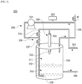
- FIG. 3 is a conceptual view illustrating a ballast water treatment apparatus 300 according to the present invention.
- the ballast water treatment apparatus 300 includes a tank 310, a spray nozzle 320 which supplies ballast water in the form of droplets into the tank 310, and a gas circulation unit 330.
- the gas circulation unit 330 includes a first gas supply line 331 which supplies inert gas to the spray nozzle 320 so that the inert gas is supplied into the tank 310 together with the ballast water, a second gas supply line 332 which supplies inert gas in the form of bubbles into the tank 310, and a gas discharge line 335 which sucks inert gas in the tank 310.
- the gas discharge line 335 may be provided to supply the sucked inert gas into the first gas supply line 331 or to supply the sucked inert gas into the second gas supply line 332 or to discharge the sucked inert gas to the outside.
- the gas circulation unit 330 may include a gas supply source 333 which supplies inert gas, a circulation pump 334 which circulates inert gas, and a bubble generator 338 which is provided in the second gas supply line 332.
- the inert gas which is sucked through the gas discharge line 335, may be supplied back to at least one line 331 or 332 of the first gas supply line 331 and the second gas supply line 332 by an operation of the circulation pump 334.
- first gas supply line 331 and the second gas supply line 332 may branch off between the circulation pump 334 and the spray nozzle 320.
- the interior of the tank 310 may include an upper region 311, and a lower region 312.
- a level of the ballast water in the tank 310 is increased from the lower region to the upper region.
- the ballast water treatment apparatus 300 may include a ballast water supply line 301 for supplying the ballast water into the tank 310.
- the treatment apparatus 300 may include a ballast water discharge line 302 for discharging the ballast water in the tank 310 to the outside.
- the ballast water discharge line 302 may be connected to the lower region 212 in the tank 310.
- one or more valves which open and close the respective lines and adjust a flow rate of the ballast water flowing through the respective lines, may be provided in the supply line 301 and the discharge line 302, respectively.
- the valve may include an electronic expansion valve or a solenoid valve.
- the spray nozzle 320 may be connected with the ballast water supply line 301 into which the ballast water flows.
- the ballast water supply line 301 may be connected with the first gas supply line 331.
- a check valve which allows gas to flow toward the spray nozzle 320, may be provided in the first gas supply line 331.
- ballast water or only the inert gas may be supplied to the spray nozzle 320.
- the ballast water and the inert gas may be supplied together to the spray nozzle 320.
- the ballast water and the inert gas may be sprayed together through the spray nozzle 320.
- the spray nozzle 320 may be provided to spray the ballast water and/or the inert gas into the upper region 311 in the tank 310.
- the spray nozzle 320 may include a nozzle body 321 into which the ballast water and the inert gas flow, and a nozzle head 322 which has one or more spray holes.
- the nozzle head 322 may be provided to be positioned in the upper region 311 in the tank 310, and the gas discharge line 335 may be provided to suck the inert gas in the upper region 311 in the tank 310 in accordance with an operation of the circulation pump 334.
- the ballast water flows in through the ballast water supply line 301, and then the ballast water flows toward the spray nozzle 320.
- the ballast water is injected into the tank 310 through the spray nozzle 320, and the injected ballast water is accommodated in the lower region of the tank 310.
- the ballast water, which is sprayed through the spray nozzle 320 is formed as droplets having predetermined sizes. In this case, a diameter of the droplet may be 2,000 ⁇ m or less.
- the inert gas may be supplied to the spray nozzle 120 through the first gas supply line 331.
- the inert gas is mixed with the ballast water, and the inert gas, together with the ballast water, may be sprayed into the tank 310 through the spray nozzle 320.
- the ballast water and the inert gas are sprayed through the spray nozzle 320, the ballast water may be sterilized (primary sterilization).
- the bubble generator 338 may be provided to be positioned in the lower region 312 in the tank 310. In addition, the bubble generator 338 may be provided to be operated when a level of the ballast water in the tank 310 is a predetermined level or higher.
- the bubble generator 338 may be provided to be operated based on internal pressure of the tank 310, or the bubble generator 338 may be provided to be operated based on a predetermined time. In this case, the bubble generator 338 may be provided to be operated for a predetermined time.
- valves may be provided in each of the lines 331, 332, and 335.
- the valve may include an electronic expansion valve, a solenoid valve, or a check valve.
- electronic expansion valves 336 and 337 are provided in the first and second gas supply lines 331 and 332, respectively.
- the inert gas (e.g., carbon dioxide) is supplied into the tank 310 through the second gas supply line 337, and the inert gas, which is supplied into the tank 310, is injected into the lower region 312 in the tank 310 through the bubble generator 338.
- the ballast water accommodated in the lower region 212 in the tank 310 comes into contact with inert gas bubbles. With the aforementioned contact, the ballast water may be sterilized (secondary sterilization).
- the bubble generator 338 may be provided to generate inert gas bubbles of 50 ⁇ m or less. Meanwhile, the remaining inert gas bubbles, which are not dissolved, move to the upper region 311 in the tank 310 due to a difference in density, and then are dissolved in the ballast water while coming into contact with the ballast water sprayed through the spray nozzle 320 or flow into the gas discharge line 335.
- the inert gas flowing into the gas discharge line 335 may be supplied back to the spray nozzle 320 through the first gas supply line 331, and may be supplied back to the bubble generator 338 through the second gas supply line 332.
- the inert gas in the tank 110 may be sucked through the gas discharge tube 135.
- the inert gas e.g., carbon dioxide
- the circulation pump 334 may be supplied to the first and/or second gas supply lines 331 and 332 through the circulation pump 334.
- ballast water in the tank 310 for which the sterilization treatment is completed, may be discharged to the outside through the ballast water discharge line 302.
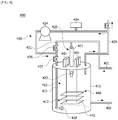
- FIG. 4 is a conceptual view illustrating a ballast water treatment apparatus according to another exemplary embodiment of the present invention.
- the ballast water treatment apparatus 400 includes a tank 410, and a spray nozzle 420 which is provided to supply the ballast water in the form of droplets into the tank 410 and spray the ballast water into the upper region in the tank 410.
- the treatment apparatus 400 includes a gas circulation unit 430.
- the gas circulation unit 420 includes one or more gas supply lines 441 and 442 which supply inert gas into at least one region of an upper region 411 and a lower region 412 in the tank 410, and a gas discharge line 435 which sucks inert gas in the upper region 411 in the tank 410.
- the treatment apparatus 400 includes an electrolysis unit 440 provided in the tank 410.
- the electrolysis unit 440 may be provided to be positioned in the lower region 411 in the tank 410.
- the electrolysis unit 440 includes one or more electrode plates 441.
- the electrolysis unit 440 may include a plurality of electrodes 442 and 443.
- the gas circulation unit 430 includes a first gas supply line 431 which supplies inert gas to the spray nozzle 420 so that the inert gas is supplied into the tank 410 together with the ballast water, a second gas supply line 432 which supplies inert gas in the form of bubbles into the tank 410, and a gas discharge line 435 which sucks inert gas in the tank 410.
- the gas circulation unit 430 may include a gas supply source 433 which supplies inert gas, a circulation pump 434 which circulates inert gas, and a bubble generator 438 which is provided in the second gas supply line 432.
- the inert gas which is sucked through the gas discharge line 435, may be supplied back to at least one line 431 or 432 of the first gas supply line 431 and the second gas supply line 432 by an operation of the circulation pump 434.
- first gas supply line 431 and the second gas supply line 432 may branch off between the circulation pump 434 and the spray nozzle 420.
- the interior of the tank 410 may include the upper region 411, and the lower region 412.
- a level of the ballast water in the tank 410 is increased from the lower region to the upper region.
- the ballast water treatment apparatus 400 may include a ballast water supply line 401 for supplying the ballast water into the tank 410.
- the treatment apparatus 400 may include a ballast water discharge line 402 for discharging the ballast water in the tank 410 to the outside.
- the ballast water discharge line 402 may be connected to the lower region 412 in the tank 410.
- one or more valves which open and close the respective lines and adjust a flow rate of the ballast water flowing through the respective lines, may be provided in the supply line 401 and the discharge line 402, respectively.
- the valve may include an electronic expansion valve or a solenoid valve.
- the spray nozzle 420 may be connected with the ballast water supply line 401 into which the ballast water flows.
- the ballast water supply line 401 may be connected with the first gas supply line 431.
- a check valve which allows gas to flow toward the spray nozzle 420, may be provided in the first gas supply line 431.
- ballast water or only the inert gas may be supplied to the spray nozzle 420.
- the ballast water and the inert gas may be supplied together to the spray nozzle 420.
- the ballast water and the inert gas may be sprayed together through the spray nozzle 420.
- the spray nozzle 420 may be provided to spray the ballast water and/or the inert gas into the upper region 411 in the tank 410.
- the spray nozzle 420 may include a nozzle body 421 into which the ballast water and the inert gas flow, and a nozzle head 422 which has one or more spray holes.
- the nozzle head 422 may be provided to be positioned in the upper region 411 in the tank 410, and the gas discharge line 435 may be provided to suck the inert gas in the upper region 411 in the tank 410 in accordance with an operation of the circulation pump 434.
- the ballast water flows in through the ballast water supply line 401, and then the ballast water flows toward the spray nozzle 420.
- the ballast water is injected into the tank 410 through the spray nozzle 420, and the injected ballast water is accommodated in the lower region of the tank 410.
- the ballast water which is sprayed through the spray nozzle 420, is formed as droplets having predetermined sizes.
- a diameter of the droplet may be 2,000 ⁇ m or less.
- the inert gas may be supplied to the spray nozzle 420 through the first gas supply line 431. The inert gas is mixed with the ballast water, and the inert gas, together with the ballast water, may be sprayed into the tank 410 through the spray nozzle 420. As the ballast water and the inert gas are sprayed through the spray nozzle 420, the ballast water may be sterilized (primary sterilization).
- the bubble generator 438 may be provided to be positioned in the lower region 412 in the tank 410. In addition, the bubble generator 438 may be provided to be operated when a level of the ballast water in the tank 410 is a predetermined level or higher.
- valves may be provided in each of the lines 431, 432, and 435.
- the valve may include an electronic expansion valve, a solenoid valve, or a check valve.
- electronic expansion valves 436 and 437 may be provided in the first and second gas supply lines 431 and 432, respectively.
- the inert gas e.g. carbon dioxide
- the inert gas is supplied into the tank 410 through the second gas supply line 437, and the inert gas, which is supplied into the tank 410, is injected into the lower region 412 in the tank 410 through the bubble generator 438.
- the ballast water accommodated in the lower region 412 in the tank 410 comes into contact with inert gas bubbles. With the aforementioned contact, the ballast water may be sterilized (secondary sterilization).
- the bubble generator 438 may be provided to generate inert gas bubbles of 50 ⁇ m or less. Meanwhile, the remaining inert gas bubbles, which are not dissolved, move to the upper region 411 in the tank 410 due to a difference in density, and then are dissolved in the ballast water while coming into contact with the ballast water sprayed through the spray nozzle 420 or flow into the gas discharge line 435.
- the inert gas flowing into the gas discharge line 435 may be supplied back to the spray nozzle 420 through the first gas supply line 431, and may be supplied back to the bubble generator 438 through the second gas supply line 432.
- ballast water in which carbon dioxide is dissolved concentration of oxygen in the ballast water is decreased, ion concentration is increased due to the dissolved carbon dioxide, and the pH (hydrogen ion concentration exponent) is decreased.
- concentration of carbon dioxide in the tank 410 is increased, such that the ballast water injected into the tank 410 is sterilized.
- the sterilization treatment for the ballast water may be carried out not only by the contact between the ballast water accommodated in the lower region 412 in the tank 410 and carbon dioxide sprayed by the bubble generator 438, but also by the electrolysis unit 440 at the electrode plate 441 to which a predetermined electric current (for example, 3A) is supplied. During this process, carbon dioxide, hydrogen, oxygen, and chlorine gas are present in the tank 410.
- carbon dioxide, hydrogen, oxygen, or chlorine may flow into the gas circulation unit 430 through the gas discharge line 435.
- the carbon dioxide discharged to the gas circulation unit 430 moves to the first gas supply line 431 and/or the second gas supply line 432 through the circulation pump 434 provided to reuse the carbon dioxide.
- the ballast water for which the sterilization treatment is completed, is transferred to the outside of the tank 410 through the ballast water discharge line 402.
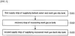
- FIG. 5 is a flowchart illustrating a ballast water treatment method.
- the treatment method includes a first supply step S101 of supplying the ballast water and the inert gas into the tank, a recovery step S102 of recovering the inert gas in the tank, and a second supply step S103 of supplying the recovered inert gas back into the tank.
- the ballast water and the inert gas may be sprayed together into the tank through the spray nozzle.
- the ballast water may be sprayed into the upper region in the tank through the spray nozzle, and the inert gas may be sprayed into the lower region in the tank through the bubble generator.
- the inert gas in the upper region in the tank may be recovered through the gas discharge line and the circulation pump, and the recovered inert gas may be supplied back into the tank.
- FIG. 6 is a graph illustrating a change of solubility of carbon dioxide in ballast water with respect to internal pressure of a tank of the ballast water treatment apparatus according to the present invention.
- artificial seawater is synthesized by using sea salt powder (Product No. S9883) that is a standard of seawater of Sigma Aldrich Inc., and salinity is 30 PSU (Practical Salinity Unit).
- sea salt powder Product No. S9883
- salinity is 30 PSU (Practical Salinity Unit).
- the produced artificial seawater was injected into the tank, and thereafter, a gaseous state in the sealed tank to which the artificial seawater is injected was purged by carbon dioxide under a normal pressure condition.
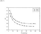
- FIG. 7 is a graph illustrating a change in the pH (hydrogen ion concentration exponent) of ballast water with respect to internal pressure of the tank of the ballast water treatment apparatus according to the invention.
- the artificial seawater which is produced to have salinity of 30 PSU, was injected into the tank, a pH meter (hydrogen ion concentration measuring device) was attached at a lower end of the tank, and thereafter, and the pH of the artificial seawater was measured in accordance with pressure of carbon dioxide in the tank.
- a pH meter hydrogen ion concentration measuring device
- the pH of the artificial seawater is decreased as the internal pressure of the tank is increased, and the pH of the artificial seawater is decreased under an equal pressure condition as the temperature of the artificial seawater is increased.
- FIG. 8 is an image illustrating a state of marine microbes in ballast water before a sterilization treatment using carbon dioxide
- FIG. 9 is an image illustrating a change of marine microbes in ballast water after a sterilization treatment using carbon dioxide.
- FIG. 10 is a microscope image at 400x magnification illustrating a state of marine microbes in ballast water before a sterilization treatment using carbon dioxide
- FIG. 11 is a microscope image at 400x magnification illustrating a state in which marine microbes are dead in ballast water after a sterilization treatment using carbon dioxide.
- artemias which are marine microbes, were incubated in the artificial seawater that was produced to have salinity of 30 PSU, and injected into the sealed tank, and thereafter, behavior of the artemias was observed while carbon dioxide is injected into the tank. It can be observed that the artificial seawater in which the artemias are incubated has high turbidity, and the artemias swim in the artificial seawater.
- the artificial seawater in which the artemias were incubated was injected into the sealed tank, pressure in the sealed tank was maintained to IMPa (10 bar) for 5 minutes by injecting carbon dioxide, and thereafter, the artificial seawater discharged through a ballast water discharge port was observed. It could be seen that a plurality of artemias in the artificial seawater did not swim, and sank to a lower end of the artificial seawater.
- behavior of the artemias in the artificial seawater was intended to be checked by using an ocular lens with 10X magnification and an objective lens with 40X magnification of E600 of Nikon Corporation, and artemias, which have a size of about 300 ⁇ m and active motility, can be observed in the artificial seawater that is not treated by carbon dioxide.
- artemias which have a size of about 250 ⁇ m and do not move, can be observed in the artificial seawater that is treated by carbon dioxide.
Landscapes
- Engineering & Computer Science (AREA)
- Chemical & Material Sciences (AREA)
- Environmental & Geological Engineering (AREA)
- Water Supply & Treatment (AREA)
- Life Sciences & Earth Sciences (AREA)
- Hydrology & Water Resources (AREA)
- Organic Chemistry (AREA)
- Ocean & Marine Engineering (AREA)
- Mechanical Engineering (AREA)
- Combustion & Propulsion (AREA)
- Toxicology (AREA)
- General Health & Medical Sciences (AREA)
- Public Health (AREA)
- Health & Medical Sciences (AREA)
- Chemical Kinetics & Catalysis (AREA)
- Electrochemistry (AREA)
- General Chemical & Material Sciences (AREA)
- Water Treatment By Electricity Or Magnetism (AREA)
- Apparatus For Disinfection Or Sterilisation (AREA)
Claims (4)
- Eine Behandlungsvorrichtung (300) für Ballastwasser umfassend:einen Tank (310);eine Sprühdüse (320), die Ballastwasser in Form von Tröpfchen in den Tank (310) zuführt; undeine Gaszirkulationseinheit (330), die Inertgas in den Tank (310) zuführt und Inertgas ansaugt, das nicht im Ballastwasser im Tank (310) gelöst ist,wobei die Gaszirkulationseinheit (330) dazu vorgesehen ist, das angesaugte Inertgas zurück in den Tank (310) zuzuführen,dadurch gekennzeichnet, dass die Gaszirkulationseinheit eine erste Gaszufuhrleitung (331) aufweist, die der Sprühdüse (320) Inertgas zuführt, eine zweite Gaszufuhrleitung (332), die Inertgas in Form von Blasen in den Tank zuführt, und eine Gasableitung (335), die Inertgas in den Tank (310) ansaugt, undwobei die Gasableitung (335) vorgesehen ist, um das angesaugte Inertgas in die erste Gaszufuhrleitung (331) zuzuführen und das angesaugte Inertgas in die zweite Gaszufuhrleitung (332) zuzuführen und das angesaugte Inertgas nach außen abzuleiten, undwobei die Gaszirkulationseinheit eine Gaszufuhrquelle (333), die Inertgas sowohl in die erste Gaszufuhrleitung (331) als auch in die zweite Gaszufuhrleitung (332) zuführt, eine Zirkulationspumpe (334), die das Inertgas zirkuliert, und einen Blasengenerator (338), der in der zweiten Gasversorgungsleitung (333) vorgesehen ist, einschließt, undwobei die Sprühdüse (320) vorgesehen ist, um das Ballastwasser in einen oberen Bereich (311) in den Tank (310) zu sprühen, wobei die Gasableitung (335) vorgesehen ist, um durch einen Betrieb der Zirkulationspumpe (334) das Inertgas im oberen Bereich (311) in den Tank (310) anzusaugen, und wobei der Blasengenerator (338) in einem unteren Bereich (312) im Tank positioniert ist, undwobei elektronische Expansionsventile 336 und 337 in den ersten und zweiten Gasversorgungsleitungen 331 und 332 vorgesehen sind.
- Die Behandlungsvorrichtung (300) für Ballastwasser nach Anspruch 1, wobei die Sprühdüse (320) einschließt:eine Zufuhrleitung (301) für Ballastwasser, die mit der ersten Gaszufuhrleitung (331) verbunden ist und mit dem Ballastwasser versorgt wird;einen Düsenkörper (321), in den das Ballastwasser und das Inertgas durch die Zufuhrleitung (301) für Ballastwasser und die erste Gaszufuhrleitung (331) strömen; undeinen Düsenkopf, der ein oder mehrere Sprühlöcher aufweist.
- Die Behandlungsvorrichtung (300) für Ballastwasser nach Anspruch 1, wobei die erste Gaszufuhrleitung (331) und die zweite Gaszufuhrleitung (332) zwischen der Umwälzpumpe (334) und der Sprühdüse (320) abzweigen.
- Die Behandlungsvorrichtung (300) für Ballastwasser nach Anspruch 1, die weiterhin einschließt:
eine Elektrolyseeinheit (440), die eine oder mehrere Elektrodenplatten (441) enthält und in dem Tank (410) vorgesehen ist.
Applications Claiming Priority (1)
| Application Number | Priority Date | Filing Date | Title |
|---|---|---|---|
| KR1020140103869A KR101520586B1 (ko) | 2014-08-11 | 2014-08-11 | 선박 평형수 처리 장치 및 처리 방법 |
Publications (2)
| Publication Number | Publication Date |
|---|---|
| EP2985263A1 EP2985263A1 (de) | 2016-02-17 |
| EP2985263B1 true EP2985263B1 (de) | 2019-01-09 |
Family
ID=53394796
Family Applications (1)
| Application Number | Title | Priority Date | Filing Date |
|---|---|---|---|
| EP15180148.7A Not-in-force EP2985263B1 (de) | 2014-08-11 | 2015-08-07 | Vorrichtung zur behandlung von ballastwasser |
Country Status (3)
| Country | Link |
|---|---|
| US (1) | US10266432B2 (de) |
| EP (1) | EP2985263B1 (de) |
| KR (1) | KR101520586B1 (de) |
Families Citing this family (2)
| Publication number | Priority date | Publication date | Assignee | Title |
|---|---|---|---|---|
| WO2013192000A2 (en) * | 2012-06-18 | 2013-12-27 | The Government Of The Usa Of America As Represented By The Secretary Of The Dept. Of The Interior | Nozzle mixing methods for ship ballast tanks |
| KR20230041481A (ko) * | 2021-09-17 | 2023-03-24 | 한국조선해양 주식회사 | 선박 평형수 처리 시스템 및 이를 포함하는 선박 |
Family Cites Families (12)
| Publication number | Priority date | Publication date | Assignee | Title |
|---|---|---|---|---|
| US6722933B2 (en) * | 2001-05-25 | 2004-04-20 | Mh Systems, Inc. | Closed loop control of both pressure and content of ballast tank gases to at different times kill both aerobic and anaerobic organisms within ballast water |
| US20030205136A1 (en) * | 2002-05-02 | 2003-11-06 | Mcnulty Peter Drummond | System and method of water treatment |
| KR100542895B1 (ko) | 2003-12-22 | 2006-01-11 | 재단법인 포항산업과학연구원 | 차아염소산나트륨을 이용한 전해식 밸러스트수 처리방법및 처리장치 |
| EP1751063A1 (de) * | 2004-05-11 | 2007-02-14 | Metafil AS | Ballastwassersystem |
| KR100840762B1 (ko) | 2006-10-14 | 2008-06-23 | 창원환경산업 주식회사 | 복극식 전기분해시스템을 이용한 선박 밸러스트수 살균장치 |
| SE531425C2 (sv) * | 2007-05-29 | 2009-03-31 | Scanjet Marine Ab | Anordning för rengöring av slutna utrymmen |
| JP5429589B2 (ja) * | 2008-06-12 | 2014-02-26 | 国立大学法人東京工業大学 | 塗装された金属面の塗装状態の定量的な評価方法及びシステム |
| KR100883444B1 (ko) * | 2008-07-24 | 2009-02-17 | (주) 테크윈 | 발라스트수 처리 장치 및 방법 |
| GB2470070B (en) * | 2009-05-08 | 2012-05-16 | Coldharbour Marine Ltd | Liquid pump apparatus and method |
| JP5394340B2 (ja) * | 2010-08-31 | 2014-01-22 | 株式会社日立パワーソリューションズ | アンモニア除去装置 |
| DK201170108A (da) * | 2011-03-03 | 2012-09-04 | Bawat As | System til behandling af ballastvand i ballasttanke |
| KR101465739B1 (ko) * | 2012-11-15 | 2014-11-28 | 삼성중공업 주식회사 | 밸러스트 탱크 가스 포집 장치 |
-
2014
- 2014-08-11 KR KR1020140103869A patent/KR101520586B1/ko active Active
-
2015
- 2015-08-07 EP EP15180148.7A patent/EP2985263B1/de not_active Not-in-force
- 2015-08-10 US US14/821,821 patent/US10266432B2/en active Active
Non-Patent Citations (1)
| Title |
|---|
| None * |
Also Published As
| Publication number | Publication date |
|---|---|
| US20160039690A1 (en) | 2016-02-11 |
| KR101520586B1 (ko) | 2015-05-15 |
| US10266432B2 (en) | 2019-04-23 |
| EP2985263A1 (de) | 2016-02-17 |
Similar Documents
| Publication | Publication Date | Title |
|---|---|---|
| KR101066674B1 (ko) | 전기분해 유닛과 이러한 전기분해 유닛을 이용한 선박의 발라스트 수 처리장치 | |
| CN102105406B (zh) | 压舱水处理装置及方法 | |
| KR101349314B1 (ko) | 선박용 밸러스트수 처리장치 및 처리방법 | |
| KR101313625B1 (ko) | 평형수 순환 시스템 및 이를 갖춘 선박 | |
| JP2007515289A (ja) | 電解式バラスト水処理装置および処理方法 | |
| KR101358323B1 (ko) | 밸러스트 수 처리 시스템을 포함하는 선박 | |
| JP5431208B2 (ja) | バラスト水処理装置 | |
| US10266432B2 (en) | Apparatus and method for treating ballast water | |
| KR100549838B1 (ko) | 선박의 발라스트수 처리장치 및 방법 | |
| KR20170047516A (ko) | 선박 평형수 처리 장치 | |
| KR102159846B1 (ko) | 선박 평형수 처리 시스템 | |
| KR200349496Y1 (ko) | 선박의 발라스트수 처리장치 | |
| US11192806B2 (en) | Ballast water treatment system and method | |
| KR101784916B1 (ko) | 밸러스트수 처리 시스템 | |
| KR101816807B1 (ko) | 스케일 제거 시스템을 구비한 밸러스트 수 처리장치 | |
| KR20160064484A (ko) | 밸러스트수 처리 시스템을 구비한 선박 | |
| KR20150055929A (ko) | 담수지역에서 사용가능한 전기분해 방식 선박평형수 처리장치 | |
| KR101163344B1 (ko) | 전기분해 유닛을 이용한 선박의 발라스트 수 처리방법 | |
| JP2008055352A (ja) | 水中のオゾンガスの微細化気泡の維持方法、維持装置及びバラスト水の処理方法 | |
| KR20150127315A (ko) | 밸러스트수 처리 장치 | |
| KR100733541B1 (ko) | 전해식 밸러스터수 처리방법 및 처리장치 | |
| KR101776045B1 (ko) | 밸러스트 수 처리장치용 가스배출 시스템 및 이를 포함하는 밸러스트 수 처리장치 | |
| KR102333211B1 (ko) | 간접 전기 분해 방식의 밸러스트수 처리 장치 | |
| KR101150275B1 (ko) | 직결식 밸러스트수 처리방법과 처리장치 | |
| KR20160136728A (ko) | 선박 평형수 중화장치 |
Legal Events
| Date | Code | Title | Description |
|---|---|---|---|
| PUAI | Public reference made under article 153(3) epc to a published international application that has entered the european phase |
Free format text: ORIGINAL CODE: 0009012 |
|
| 17P | Request for examination filed |
Effective date: 20150819 |
|
| AK | Designated contracting states |
Kind code of ref document: A1 Designated state(s): AL AT BE BG CH CY CZ DE DK EE ES FI FR GB GR HR HU IE IS IT LI LT LU LV MC MK MT NL NO PL PT RO RS SE SI SK SM TR |
|
| AX | Request for extension of the european patent |
Extension state: BA ME |
|
| STAA | Information on the status of an ep patent application or granted ep patent |
Free format text: STATUS: EXAMINATION IS IN PROGRESS |
|
| 17Q | First examination report despatched |
Effective date: 20180306 |
|
| GRAP | Despatch of communication of intention to grant a patent |
Free format text: ORIGINAL CODE: EPIDOSNIGR1 |
|
| STAA | Information on the status of an ep patent application or granted ep patent |
Free format text: STATUS: GRANT OF PATENT IS INTENDED |
|
| INTG | Intention to grant announced |
Effective date: 20180920 |
|
| GRAS | Grant fee paid |
Free format text: ORIGINAL CODE: EPIDOSNIGR3 |
|
| GRAA | (expected) grant |
Free format text: ORIGINAL CODE: 0009210 |
|
| STAA | Information on the status of an ep patent application or granted ep patent |
Free format text: STATUS: THE PATENT HAS BEEN GRANTED |
|
| AK | Designated contracting states |
Kind code of ref document: B1 Designated state(s): AL AT BE BG CH CY CZ DE DK EE ES FI FR GB GR HR HU IE IS IT LI LT LU LV MC MK MT NL NO PL PT RO RS SE SI SK SM TR |
|
| REG | Reference to a national code |
Ref country code: GB Ref legal event code: FG4D |
|
| REG | Reference to a national code |
Ref country code: CH Ref legal event code: EP Ref country code: AT Ref legal event code: REF Ref document number: 1087072 Country of ref document: AT Kind code of ref document: T Effective date: 20190115 |
|
| REG | Reference to a national code |
Ref country code: DE Ref legal event code: R096 Ref document number: 602015023077 Country of ref document: DE |
|
| REG | Reference to a national code |
Ref country code: IE Ref legal event code: FG4D |
|
| REG | Reference to a national code |
Ref country code: NL Ref legal event code: MP Effective date: 20190109 |
|
| REG | Reference to a national code |
Ref country code: LT Ref legal event code: MG4D |
|
| PG25 | Lapsed in a contracting state [announced via postgrant information from national office to epo] |
Ref country code: NL Free format text: LAPSE BECAUSE OF FAILURE TO SUBMIT A TRANSLATION OF THE DESCRIPTION OR TO PAY THE FEE WITHIN THE PRESCRIBED TIME-LIMIT Effective date: 20190109 |
|
| REG | Reference to a national code |
Ref country code: AT Ref legal event code: MK05 Ref document number: 1087072 Country of ref document: AT Kind code of ref document: T Effective date: 20190109 |
|
| PG25 | Lapsed in a contracting state [announced via postgrant information from national office to epo] |
Ref country code: FI Free format text: LAPSE BECAUSE OF FAILURE TO SUBMIT A TRANSLATION OF THE DESCRIPTION OR TO PAY THE FEE WITHIN THE PRESCRIBED TIME-LIMIT Effective date: 20190109 Ref country code: PL Free format text: LAPSE BECAUSE OF FAILURE TO SUBMIT A TRANSLATION OF THE DESCRIPTION OR TO PAY THE FEE WITHIN THE PRESCRIBED TIME-LIMIT Effective date: 20190109 Ref country code: LT Free format text: LAPSE BECAUSE OF FAILURE TO SUBMIT A TRANSLATION OF THE DESCRIPTION OR TO PAY THE FEE WITHIN THE PRESCRIBED TIME-LIMIT Effective date: 20190109 Ref country code: SE Free format text: LAPSE BECAUSE OF FAILURE TO SUBMIT A TRANSLATION OF THE DESCRIPTION OR TO PAY THE FEE WITHIN THE PRESCRIBED TIME-LIMIT Effective date: 20190109 Ref country code: PT Free format text: LAPSE BECAUSE OF FAILURE TO SUBMIT A TRANSLATION OF THE DESCRIPTION OR TO PAY THE FEE WITHIN THE PRESCRIBED TIME-LIMIT Effective date: 20190509 Ref country code: NO Free format text: LAPSE BECAUSE OF FAILURE TO SUBMIT A TRANSLATION OF THE DESCRIPTION OR TO PAY THE FEE WITHIN THE PRESCRIBED TIME-LIMIT Effective date: 20190409 Ref country code: ES Free format text: LAPSE BECAUSE OF FAILURE TO SUBMIT A TRANSLATION OF THE DESCRIPTION OR TO PAY THE FEE WITHIN THE PRESCRIBED TIME-LIMIT Effective date: 20190109 |
|
| PG25 | Lapsed in a contracting state [announced via postgrant information from national office to epo] |
Ref country code: GR Free format text: LAPSE BECAUSE OF FAILURE TO SUBMIT A TRANSLATION OF THE DESCRIPTION OR TO PAY THE FEE WITHIN THE PRESCRIBED TIME-LIMIT Effective date: 20190410 Ref country code: BG Free format text: LAPSE BECAUSE OF FAILURE TO SUBMIT A TRANSLATION OF THE DESCRIPTION OR TO PAY THE FEE WITHIN THE PRESCRIBED TIME-LIMIT Effective date: 20190409 Ref country code: RS Free format text: LAPSE BECAUSE OF FAILURE TO SUBMIT A TRANSLATION OF THE DESCRIPTION OR TO PAY THE FEE WITHIN THE PRESCRIBED TIME-LIMIT Effective date: 20190109 Ref country code: HR Free format text: LAPSE BECAUSE OF FAILURE TO SUBMIT A TRANSLATION OF THE DESCRIPTION OR TO PAY THE FEE WITHIN THE PRESCRIBED TIME-LIMIT Effective date: 20190109 Ref country code: LV Free format text: LAPSE BECAUSE OF FAILURE TO SUBMIT A TRANSLATION OF THE DESCRIPTION OR TO PAY THE FEE WITHIN THE PRESCRIBED TIME-LIMIT Effective date: 20190109 Ref country code: IS Free format text: LAPSE BECAUSE OF FAILURE TO SUBMIT A TRANSLATION OF THE DESCRIPTION OR TO PAY THE FEE WITHIN THE PRESCRIBED TIME-LIMIT Effective date: 20190509 |
|
| REG | Reference to a national code |
Ref country code: DE Ref legal event code: R097 Ref document number: 602015023077 Country of ref document: DE |
|
| PG25 | Lapsed in a contracting state [announced via postgrant information from national office to epo] |
Ref country code: AT Free format text: LAPSE BECAUSE OF FAILURE TO SUBMIT A TRANSLATION OF THE DESCRIPTION OR TO PAY THE FEE WITHIN THE PRESCRIBED TIME-LIMIT Effective date: 20190109 Ref country code: AL Free format text: LAPSE BECAUSE OF FAILURE TO SUBMIT A TRANSLATION OF THE DESCRIPTION OR TO PAY THE FEE WITHIN THE PRESCRIBED TIME-LIMIT Effective date: 20190109 Ref country code: EE Free format text: LAPSE BECAUSE OF FAILURE TO SUBMIT A TRANSLATION OF THE DESCRIPTION OR TO PAY THE FEE WITHIN THE PRESCRIBED TIME-LIMIT Effective date: 20190109 Ref country code: DK Free format text: LAPSE BECAUSE OF FAILURE TO SUBMIT A TRANSLATION OF THE DESCRIPTION OR TO PAY THE FEE WITHIN THE PRESCRIBED TIME-LIMIT Effective date: 20190109 Ref country code: IT Free format text: LAPSE BECAUSE OF FAILURE TO SUBMIT A TRANSLATION OF THE DESCRIPTION OR TO PAY THE FEE WITHIN THE PRESCRIBED TIME-LIMIT Effective date: 20190109 Ref country code: SK Free format text: LAPSE BECAUSE OF FAILURE TO SUBMIT A TRANSLATION OF THE DESCRIPTION OR TO PAY THE FEE WITHIN THE PRESCRIBED TIME-LIMIT Effective date: 20190109 Ref country code: CZ Free format text: LAPSE BECAUSE OF FAILURE TO SUBMIT A TRANSLATION OF THE DESCRIPTION OR TO PAY THE FEE WITHIN THE PRESCRIBED TIME-LIMIT Effective date: 20190109 Ref country code: RO Free format text: LAPSE BECAUSE OF FAILURE TO SUBMIT A TRANSLATION OF THE DESCRIPTION OR TO PAY THE FEE WITHIN THE PRESCRIBED TIME-LIMIT Effective date: 20190109 |
|
| PLBE | No opposition filed within time limit |
Free format text: ORIGINAL CODE: 0009261 |
|
| STAA | Information on the status of an ep patent application or granted ep patent |
Free format text: STATUS: NO OPPOSITION FILED WITHIN TIME LIMIT |
|
| PG25 | Lapsed in a contracting state [announced via postgrant information from national office to epo] |
Ref country code: SM Free format text: LAPSE BECAUSE OF FAILURE TO SUBMIT A TRANSLATION OF THE DESCRIPTION OR TO PAY THE FEE WITHIN THE PRESCRIBED TIME-LIMIT Effective date: 20190109 |
|
| 26N | No opposition filed |
Effective date: 20191010 |
|
| PG25 | Lapsed in a contracting state [announced via postgrant information from national office to epo] |
Ref country code: SI Free format text: LAPSE BECAUSE OF FAILURE TO SUBMIT A TRANSLATION OF THE DESCRIPTION OR TO PAY THE FEE WITHIN THE PRESCRIBED TIME-LIMIT Effective date: 20190109 |
|
| PG25 | Lapsed in a contracting state [announced via postgrant information from national office to epo] |
Ref country code: TR Free format text: LAPSE BECAUSE OF FAILURE TO SUBMIT A TRANSLATION OF THE DESCRIPTION OR TO PAY THE FEE WITHIN THE PRESCRIBED TIME-LIMIT Effective date: 20190109 |
|
| PG25 | Lapsed in a contracting state [announced via postgrant information from national office to epo] |
Ref country code: CH Free format text: LAPSE BECAUSE OF NON-PAYMENT OF DUE FEES Effective date: 20190831 Ref country code: LU Free format text: LAPSE BECAUSE OF NON-PAYMENT OF DUE FEES Effective date: 20190807 Ref country code: MC Free format text: LAPSE BECAUSE OF FAILURE TO SUBMIT A TRANSLATION OF THE DESCRIPTION OR TO PAY THE FEE WITHIN THE PRESCRIBED TIME-LIMIT Effective date: 20190109 Ref country code: LI Free format text: LAPSE BECAUSE OF NON-PAYMENT OF DUE FEES Effective date: 20190831 |
|
| REG | Reference to a national code |
Ref country code: BE Ref legal event code: MM Effective date: 20190831 |
|
| PG25 | Lapsed in a contracting state [announced via postgrant information from national office to epo] |
Ref country code: IE Free format text: LAPSE BECAUSE OF NON-PAYMENT OF DUE FEES Effective date: 20190807 |
|
| PG25 | Lapsed in a contracting state [announced via postgrant information from national office to epo] |
Ref country code: BE Free format text: LAPSE BECAUSE OF NON-PAYMENT OF DUE FEES Effective date: 20190831 |
|
| PG25 | Lapsed in a contracting state [announced via postgrant information from national office to epo] |
Ref country code: CY Free format text: LAPSE BECAUSE OF FAILURE TO SUBMIT A TRANSLATION OF THE DESCRIPTION OR TO PAY THE FEE WITHIN THE PRESCRIBED TIME-LIMIT Effective date: 20190109 |
|
| PG25 | Lapsed in a contracting state [announced via postgrant information from national office to epo] |
Ref country code: HU Free format text: LAPSE BECAUSE OF FAILURE TO SUBMIT A TRANSLATION OF THE DESCRIPTION OR TO PAY THE FEE WITHIN THE PRESCRIBED TIME-LIMIT; INVALID AB INITIO Effective date: 20150807 Ref country code: MT Free format text: LAPSE BECAUSE OF FAILURE TO SUBMIT A TRANSLATION OF THE DESCRIPTION OR TO PAY THE FEE WITHIN THE PRESCRIBED TIME-LIMIT Effective date: 20190109 |
|
| PG25 | Lapsed in a contracting state [announced via postgrant information from national office to epo] |
Ref country code: MK Free format text: LAPSE BECAUSE OF FAILURE TO SUBMIT A TRANSLATION OF THE DESCRIPTION OR TO PAY THE FEE WITHIN THE PRESCRIBED TIME-LIMIT Effective date: 20190109 |
|
| PGFP | Annual fee paid to national office [announced via postgrant information from national office to epo] |
Ref country code: GB Payment date: 20230821 Year of fee payment: 9 |
|
| PGFP | Annual fee paid to national office [announced via postgrant information from national office to epo] |
Ref country code: FR Payment date: 20230821 Year of fee payment: 9 Ref country code: DE Payment date: 20230822 Year of fee payment: 9 |
|
| REG | Reference to a national code |
Ref country code: DE Ref legal event code: R119 Ref document number: 602015023077 Country of ref document: DE |
|
| GBPC | Gb: european patent ceased through non-payment of renewal fee |
Effective date: 20240807 |
|
| PG25 | Lapsed in a contracting state [announced via postgrant information from national office to epo] |
Ref country code: DE Free format text: LAPSE BECAUSE OF NON-PAYMENT OF DUE FEES Effective date: 20250301 |
|
| PG25 | Lapsed in a contracting state [announced via postgrant information from national office to epo] |
Ref country code: GB Free format text: LAPSE BECAUSE OF NON-PAYMENT OF DUE FEES Effective date: 20240807 |
|
| PG25 | Lapsed in a contracting state [announced via postgrant information from national office to epo] |
Ref country code: FR Free format text: LAPSE BECAUSE OF NON-PAYMENT OF DUE FEES Effective date: 20240831 |