EP2983780B1 - Irradiation device - Google Patents
Irradiation device Download PDFInfo
- Publication number
- EP2983780B1 EP2983780B1 EP14715950.3A EP14715950A EP2983780B1 EP 2983780 B1 EP2983780 B1 EP 2983780B1 EP 14715950 A EP14715950 A EP 14715950A EP 2983780 B1 EP2983780 B1 EP 2983780B1
- Authority
- EP
- European Patent Office
- Prior art keywords
- housing
- led lamp
- lamp system
- housing part
- power source
- Prior art date
- Legal status (The legal status is an assumption and is not a legal conclusion. Google has not performed a legal analysis and makes no representation as to the accuracy of the status listed.)
- Active
Links
- 238000011282 treatment Methods 0.000 claims description 139
- 239000000203 mixture Substances 0.000 claims description 59
- 238000002428 photodynamic therapy Methods 0.000 claims description 54
- 210000003679 cervix uteri Anatomy 0.000 claims description 45
- 239000002243 precursor Substances 0.000 claims description 39
- 230000008878 coupling Effects 0.000 claims description 35
- 238000010168 coupling process Methods 0.000 claims description 35
- 238000005859 coupling reaction Methods 0.000 claims description 35
- 239000012858 resilient material Substances 0.000 claims description 30
- 238000000034 method Methods 0.000 claims description 29
- 238000003780 insertion Methods 0.000 claims description 25
- 230000037431 insertion Effects 0.000 claims description 25
- ZGXJTSGNIOSYLO-UHFFFAOYSA-N 88755TAZ87 Chemical compound NCC(=O)CCC(O)=O ZGXJTSGNIOSYLO-UHFFFAOYSA-N 0.000 claims description 24
- 239000003814 drug Substances 0.000 claims description 20
- 229940079593 drug Drugs 0.000 claims description 19
- 238000004519 manufacturing process Methods 0.000 claims description 19
- 238000000465 moulding Methods 0.000 claims description 19
- 239000000463 material Substances 0.000 claims description 18
- 210000001215 vagina Anatomy 0.000 claims description 15
- 230000000295 complement effect Effects 0.000 claims description 9
- 150000003839 salts Chemical class 0.000 claims description 8
- 238000005304 joining Methods 0.000 claims description 6
- 239000012530 fluid Substances 0.000 claims description 5
- 238000007789 sealing Methods 0.000 claims description 4
- 239000003504 photosensitizing agent Substances 0.000 claims 2
- 238000005286 illumination Methods 0.000 description 34
- 125000000217 alkyl group Chemical group 0.000 description 18
- 229960002749 aminolevulinic acid Drugs 0.000 description 17
- 150000001875 compounds Chemical class 0.000 description 17
- 208000037265 diseases, disorders, signs and symptoms Diseases 0.000 description 14
- 125000003118 aryl group Chemical group 0.000 description 13
- 201000010099 disease Diseases 0.000 description 13
- 229920001296 polysiloxane Polymers 0.000 description 13
- 238000012377 drug delivery Methods 0.000 description 12
- 230000003902 lesion Effects 0.000 description 11
- 208000006105 Uterine Cervical Neoplasms Diseases 0.000 description 10
- 230000008901 benefit Effects 0.000 description 10
- 206010008342 Cervix carcinoma Diseases 0.000 description 9
- 210000004027 cell Anatomy 0.000 description 9
- 201000010881 cervical cancer Diseases 0.000 description 9
- 210000001519 tissue Anatomy 0.000 description 9
- -1 5-ALA esters Chemical class 0.000 description 8
- 241000701806 Human papillomavirus Species 0.000 description 8
- 125000004432 carbon atom Chemical group C* 0.000 description 8
- 230000000694 effects Effects 0.000 description 8
- 210000004996 female reproductive system Anatomy 0.000 description 8
- 125000004169 (C1-C6) alkyl group Chemical group 0.000 description 6
- 206010028980 Neoplasm Diseases 0.000 description 6
- 208000009608 Papillomavirus Infections Diseases 0.000 description 6
- 235000014676 Phragmites communis Nutrition 0.000 description 6
- 230000005856 abnormality Effects 0.000 description 6
- 125000004435 hydrogen atom Chemical group [H]* 0.000 description 6
- 206010008263 Cervical dysplasia Diseases 0.000 description 5
- 241000282414 Homo sapiens Species 0.000 description 5
- 241001465754 Metazoa Species 0.000 description 5
- 238000005259 measurement Methods 0.000 description 5
- 239000001301 oxygen Substances 0.000 description 5
- 229910052760 oxygen Inorganic materials 0.000 description 5
- 150000004032 porphyrins Chemical class 0.000 description 5
- 125000001424 substituent group Chemical group 0.000 description 5
- QVGXLLKOCUKJST-UHFFFAOYSA-N atomic oxygen Chemical compound [O] QVGXLLKOCUKJST-UHFFFAOYSA-N 0.000 description 4
- 201000011510 cancer Diseases 0.000 description 4
- 208000007951 cervical intraepithelial neoplasia Diseases 0.000 description 4
- 125000001309 chloro group Chemical class Cl* 0.000 description 4
- 238000010438 heat treatment Methods 0.000 description 4
- 208000020082 intraepithelial neoplasia Diseases 0.000 description 4
- 230000007257 malfunction Effects 0.000 description 4
- 125000002496 methyl group Chemical group [H]C([H])([H])* 0.000 description 4
- 238000004806 packaging method and process Methods 0.000 description 4
- 230000035935 pregnancy Effects 0.000 description 4
- 229920006395 saturated elastomer Polymers 0.000 description 4
- 239000007787 solid Substances 0.000 description 4
- 238000002560 therapeutic procedure Methods 0.000 description 4
- 239000012780 transparent material Substances 0.000 description 4
- 208000009621 actinic keratosis Diseases 0.000 description 3
- 230000004913 activation Effects 0.000 description 3
- 125000003545 alkoxy group Chemical group 0.000 description 3
- 230000001413 cellular effect Effects 0.000 description 3
- 125000001153 fluoro group Chemical group F* 0.000 description 3
- 208000015181 infectious disease Diseases 0.000 description 3
- 125000001280 n-hexyl group Chemical group C(CCCCC)* 0.000 description 3
- 125000000449 nitro group Chemical group [O-][N+](*)=O 0.000 description 3
- 231100000760 phototoxic Toxicity 0.000 description 3
- 230000008569 process Effects 0.000 description 3
- 230000002035 prolonged effect Effects 0.000 description 3
- 210000000664 rectum Anatomy 0.000 description 3
- 239000008247 solid mixture Substances 0.000 description 3
- 238000001356 surgical procedure Methods 0.000 description 3
- IJGRMHOSHXDMSA-UHFFFAOYSA-N Atomic nitrogen Chemical compound N#N IJGRMHOSHXDMSA-UHFFFAOYSA-N 0.000 description 2
- KSFOVUSSGSKXFI-GAQDCDSVSA-N CC1=C/2NC(\C=C3/N=C(/C=C4\N\C(=C/C5=N/C(=C\2)/C(C=C)=C5C)C(C=C)=C4C)C(C)=C3CCC(O)=O)=C1CCC(O)=O Chemical compound CC1=C/2NC(\C=C3/N=C(/C=C4\N\C(=C/C5=N/C(=C\2)/C(C=C)=C5C)C(C=C)=C4C)C(C)=C3CCC(O)=O)=C1CCC(O)=O KSFOVUSSGSKXFI-GAQDCDSVSA-N 0.000 description 2
- 101150070189 CIN3 gene Proteins 0.000 description 2
- MYMOFIZGZYHOMD-UHFFFAOYSA-N Dioxygen Chemical compound O=O MYMOFIZGZYHOMD-UHFFFAOYSA-N 0.000 description 2
- 206010058314 Dysplasia Diseases 0.000 description 2
- WHXSMMKQMYFTQS-UHFFFAOYSA-N Lithium Chemical compound [Li] WHXSMMKQMYFTQS-UHFFFAOYSA-N 0.000 description 2
- HBBGRARXTFLTSG-UHFFFAOYSA-N Lithium ion Chemical compound [Li+] HBBGRARXTFLTSG-UHFFFAOYSA-N 0.000 description 2
- 241000700605 Viruses Species 0.000 description 2
- 208000018777 Vulvar intraepithelial neoplasia Diseases 0.000 description 2
- 239000000853 adhesive Substances 0.000 description 2
- 230000001070 adhesive effect Effects 0.000 description 2
- 230000008859 change Effects 0.000 description 2
- 238000002512 chemotherapy Methods 0.000 description 2
- 101150005988 cin2 gene Proteins 0.000 description 2
- 238000004140 cleaning Methods 0.000 description 2
- 230000006378 damage Effects 0.000 description 2
- 230000007423 decrease Effects 0.000 description 2
- 230000001419 dependent effect Effects 0.000 description 2
- 238000011161 development Methods 0.000 description 2
- 238000010586 diagram Methods 0.000 description 2
- 150000002148 esters Chemical class 0.000 description 2
- 238000009472 formulation Methods 0.000 description 2
- 239000000499 gel Substances 0.000 description 2
- 125000005842 heteroatom Chemical group 0.000 description 2
- BTXNYTINYBABQR-UHFFFAOYSA-N hypericin Chemical compound C12=C(O)C=C(O)C(C(C=3C(O)=CC(C)=C4C=33)=O)=C2C3=C2C3=C4C(C)=CC(O)=C3C(=O)C3=C(O)C=C(O)C1=C32 BTXNYTINYBABQR-UHFFFAOYSA-N 0.000 description 2
- 229940005608 hypericin Drugs 0.000 description 2
- PHOKTTKFQUYZPI-UHFFFAOYSA-N hypericin Natural products Cc1cc(O)c2c3C(=O)C(=Cc4c(O)c5c(O)cc(O)c6c7C(=O)C(=Cc8c(C)c1c2c(c78)c(c34)c56)O)O PHOKTTKFQUYZPI-UHFFFAOYSA-N 0.000 description 2
- 230000006872 improvement Effects 0.000 description 2
- 238000001727 in vivo Methods 0.000 description 2
- 208000000509 infertility Diseases 0.000 description 2
- 230000036512 infertility Effects 0.000 description 2
- 230000003834 intracellular effect Effects 0.000 description 2
- 229940118199 levulan Drugs 0.000 description 2
- 239000007788 liquid Substances 0.000 description 2
- 229910052744 lithium Inorganic materials 0.000 description 2
- 229910001416 lithium ion Inorganic materials 0.000 description 2
- 230000007246 mechanism Effects 0.000 description 2
- 239000012528 membrane Substances 0.000 description 2
- YUUAYBAIHCDHHD-UHFFFAOYSA-N methyl 5-aminolevulinate Chemical compound COC(=O)CCC(=O)CN YUUAYBAIHCDHHD-UHFFFAOYSA-N 0.000 description 2
- 239000002674 ointment Substances 0.000 description 2
- 230000003287 optical effect Effects 0.000 description 2
- 125000001997 phenyl group Chemical group [H]C1=C([H])C([H])=C(*)C([H])=C1[H] 0.000 description 2
- 229950003776 protoporphyrin Drugs 0.000 description 2
- SSKVDVBQSWQEGJ-UHFFFAOYSA-N pseudohypericin Natural products C12=C(O)C=C(O)C(C(C=3C(O)=CC(O)=C4C=33)=O)=C2C3=C2C3=C4C(C)=CC(O)=C3C(=O)C3=C(O)C=C(O)C1=C32 SSKVDVBQSWQEGJ-UHFFFAOYSA-N 0.000 description 2
- 230000005855 radiation Effects 0.000 description 2
- 208000017520 skin disease Diseases 0.000 description 2
- 241000894007 species Species 0.000 description 2
- 230000002269 spontaneous effect Effects 0.000 description 2
- 125000000547 substituted alkyl group Chemical group 0.000 description 2
- 239000000758 substrate Substances 0.000 description 2
- 229940126585 therapeutic drug Drugs 0.000 description 2
- 230000001225 therapeutic effect Effects 0.000 description 2
- 230000001960 triggered effect Effects 0.000 description 2
- 210000004291 uterus Anatomy 0.000 description 2
- OYINILBBZAQBEV-UWJYYQICSA-N (17s,18s)-18-(2-carboxyethyl)-20-(carboxymethyl)-12-ethenyl-7-ethyl-3,8,13,17-tetramethyl-17,18,22,23-tetrahydroporphyrin-2-carboxylic acid Chemical compound N1C2=C(C)C(C=C)=C1C=C(N1)C(C)=C(CC)C1=CC(C(C)=C1C(O)=O)=NC1=C(CC(O)=O)C([C@@H](CCC(O)=O)[C@@H]1C)=NC1=C2 OYINILBBZAQBEV-UWJYYQICSA-N 0.000 description 1
- 125000004178 (C1-C4) alkyl group Chemical group 0.000 description 1
- ILBBNQMSDGAAPF-UHFFFAOYSA-N 1-(6-hydroxy-6-methylcyclohexa-2,4-dien-1-yl)propan-1-one Chemical compound CCC(=O)C1C=CC=CC1(C)O ILBBNQMSDGAAPF-UHFFFAOYSA-N 0.000 description 1
- MHIITNFQDPFSES-UHFFFAOYSA-N 25,26,27,28-tetrazahexacyclo[16.6.1.13,6.18,11.113,16.019,24]octacosa-1(25),2,4,6,8(27),9,11,13,15,17,19,21,23-tridecaene Chemical class N1C(C=C2C3=CC=CC=C3C(C=C3NC(=C4)C=C3)=N2)=CC=C1C=C1C=CC4=N1 MHIITNFQDPFSES-UHFFFAOYSA-N 0.000 description 1
- KFKRXESVMDBTNQ-UHFFFAOYSA-N 3-[18-(2-carboxylatoethyl)-8,13-bis(1-hydroxyethyl)-3,7,12,17-tetramethyl-22,23-dihydroporphyrin-21,24-diium-2-yl]propanoate Chemical class N1C2=C(C)C(C(C)O)=C1C=C(N1)C(C)=C(C(O)C)C1=CC(C(C)=C1CCC(O)=O)=NC1=CC(C(CCC(O)=O)=C1C)=NC1=C2 KFKRXESVMDBTNQ-UHFFFAOYSA-N 0.000 description 1
- QCQCHGYLTSGIGX-GHXANHINSA-N 4-[[(3ar,5ar,5br,7ar,9s,11ar,11br,13as)-5a,5b,8,8,11a-pentamethyl-3a-[(5-methylpyridine-3-carbonyl)amino]-2-oxo-1-propan-2-yl-4,5,6,7,7a,9,10,11,11b,12,13,13a-dodecahydro-3h-cyclopenta[a]chrysen-9-yl]oxy]-2,2-dimethyl-4-oxobutanoic acid Chemical compound N([C@@]12CC[C@@]3(C)[C@]4(C)CC[C@H]5C(C)(C)[C@@H](OC(=O)CC(C)(C)C(O)=O)CC[C@]5(C)[C@H]4CC[C@@H]3C1=C(C(C2)=O)C(C)C)C(=O)C1=CN=CC(C)=C1 QCQCHGYLTSGIGX-GHXANHINSA-N 0.000 description 1
- 208000002874 Acne Vulgaris Diseases 0.000 description 1
- 206010059313 Anogenital warts Diseases 0.000 description 1
- 206010004146 Basal cell carcinoma Diseases 0.000 description 1
- VSEIDZLLWQQJGK-CHOZPQDDSA-N CCC1=C(C)C2=N\C\1=C/C1=C(C)C(C(O)=O)=C(N1)\C(CC(=O)N[C@@H](CC(O)=O)C(O)=O)=C1/N=C(/C=C3\N/C(=C\2)C(C=C)=C3C)[C@@H](C)[C@@H]1CCC(O)=O Chemical compound CCC1=C(C)C2=N\C\1=C/C1=C(C)C(C(O)=O)=C(N1)\C(CC(=O)N[C@@H](CC(O)=O)C(O)=O)=C1/N=C(/C=C3\N/C(=C\2)C(C=C)=C3C)[C@@H](C)[C@@H]1CCC(O)=O VSEIDZLLWQQJGK-CHOZPQDDSA-N 0.000 description 1
- 101150061050 CIN1 gene Proteins 0.000 description 1
- 201000009030 Carcinoma Diseases 0.000 description 1
- 208000000907 Condylomata Acuminata Diseases 0.000 description 1
- LFQSCWFLJHTTHZ-UHFFFAOYSA-N Ethanol Chemical compound CCO LFQSCWFLJHTTHZ-UHFFFAOYSA-N 0.000 description 1
- IAYPIBMASNFSPL-UHFFFAOYSA-N Ethylene oxide Chemical compound C1CO1 IAYPIBMASNFSPL-UHFFFAOYSA-N 0.000 description 1
- 208000032843 Hemorrhage Diseases 0.000 description 1
- 241000282412 Homo Species 0.000 description 1
- DGAQECJNVWCQMB-PUAWFVPOSA-M Ilexoside XXIX Chemical compound C[C@@H]1CC[C@@]2(CC[C@@]3(C(=CC[C@H]4[C@]3(CC[C@@H]5[C@@]4(CC[C@@H](C5(C)C)OS(=O)(=O)[O-])C)C)[C@@H]2[C@]1(C)O)C)C(=O)O[C@H]6[C@@H]([C@H]([C@@H]([C@H](O6)CO)O)O)O.[Na+] DGAQECJNVWCQMB-PUAWFVPOSA-M 0.000 description 1
- 229910002993 LiMnO2 Inorganic materials 0.000 description 1
- LYPFDBRUNKHDGX-SOGSVHMOSA-N N1C2=CC=C1\C(=C1\C=CC(=N1)\C(=C1\C=C/C(/N1)=C(/C1=N/C(/CC1)=C2/C1=CC(O)=CC=C1)C1=CC(O)=CC=C1)\C1=CC(O)=CC=C1)C1=CC(O)=CC=C1 Chemical compound N1C2=CC=C1\C(=C1\C=CC(=N1)\C(=C1\C=C/C(/N1)=C(/C1=N/C(/CC1)=C2/C1=CC(O)=CC=C1)C1=CC(O)=CC=C1)\C1=CC(O)=CC=C1)C1=CC(O)=CC=C1 LYPFDBRUNKHDGX-SOGSVHMOSA-N 0.000 description 1
- 208000031481 Pathologic Constriction Diseases 0.000 description 1
- 208000006994 Precancerous Conditions Diseases 0.000 description 1
- NINIDFKCEFEMDL-UHFFFAOYSA-N Sulfur Chemical compound [S] NINIDFKCEFEMDL-UHFFFAOYSA-N 0.000 description 1
- 239000005864 Sulphur Substances 0.000 description 1
- 201000003761 Vaginal carcinoma Diseases 0.000 description 1
- 206010046905 Vaginal dysplasia Diseases 0.000 description 1
- 206010047741 Vulval cancer Diseases 0.000 description 1
- 208000004354 Vulvar Neoplasms Diseases 0.000 description 1
- KMWBBMXGHHLDKL-UHFFFAOYSA-N [AlH3].[Si] Chemical compound [AlH3].[Si] KMWBBMXGHHLDKL-UHFFFAOYSA-N 0.000 description 1
- 238000009825 accumulation Methods 0.000 description 1
- 206010000496 acne Diseases 0.000 description 1
- 125000004423 acyloxy group Chemical group 0.000 description 1
- 125000001931 aliphatic group Chemical group 0.000 description 1
- 125000003342 alkenyl group Chemical group 0.000 description 1
- 125000005194 alkoxycarbonyloxy group Chemical group 0.000 description 1
- 125000000304 alkynyl group Chemical group 0.000 description 1
- 210000003484 anatomy Anatomy 0.000 description 1
- 208000025009 anogenital human papillomavirus infection Diseases 0.000 description 1
- 201000004201 anogenital venereal wart Diseases 0.000 description 1
- 239000003242 anti bacterial agent Substances 0.000 description 1
- 230000003466 anti-cipated effect Effects 0.000 description 1
- 239000012635 anticancer drug combination Substances 0.000 description 1
- 239000003429 antifungal agent Substances 0.000 description 1
- 229940121375 antifungal agent Drugs 0.000 description 1
- 239000002246 antineoplastic agent Substances 0.000 description 1
- 239000003443 antiviral agent Substances 0.000 description 1
- 238000003782 apoptosis assay Methods 0.000 description 1
- 230000006907 apoptotic process Effects 0.000 description 1
- 238000013459 approach Methods 0.000 description 1
- 238000003491 array Methods 0.000 description 1
- 150000004036 bacteriochlorins Chemical class 0.000 description 1
- 238000005452 bending Methods 0.000 description 1
- 230000009286 beneficial effect Effects 0.000 description 1
- 230000005540 biological transmission Effects 0.000 description 1
- 230000015572 biosynthetic process Effects 0.000 description 1
- 208000034158 bleeding Diseases 0.000 description 1
- 230000000740 bleeding effect Effects 0.000 description 1
- 230000000903 blocking effect Effects 0.000 description 1
- 230000036760 body temperature Effects 0.000 description 1
- 125000001246 bromo group Chemical group Br* 0.000 description 1
- 230000030833 cell death Effects 0.000 description 1
- 210000000170 cell membrane Anatomy 0.000 description 1
- 238000006243 chemical reaction Methods 0.000 description 1
- 235000017168 chlorine Nutrition 0.000 description 1
- 150000004035 chlorins Chemical class 0.000 description 1
- DQLATGHUWYMOKM-UHFFFAOYSA-L cisplatin Chemical compound N[Pt](N)(Cl)Cl DQLATGHUWYMOKM-UHFFFAOYSA-L 0.000 description 1
- 229960004316 cisplatin Drugs 0.000 description 1
- 238000002573 colposcopy Methods 0.000 description 1
- 238000010276 construction Methods 0.000 description 1
- 238000011109 contamination Methods 0.000 description 1
- 239000003433 contraceptive agent Substances 0.000 description 1
- 230000002254 contraceptive effect Effects 0.000 description 1
- 229920001577 copolymer Polymers 0.000 description 1
- 239000006071 cream Substances 0.000 description 1
- 125000004122 cyclic group Chemical group 0.000 description 1
- 230000009849 deactivation Effects 0.000 description 1
- 238000013461 design Methods 0.000 description 1
- 239000000645 desinfectant Substances 0.000 description 1
- 238000001514 detection method Methods 0.000 description 1
- 229910003460 diamond Inorganic materials 0.000 description 1
- 239000010432 diamond Substances 0.000 description 1
- 208000035475 disorder Diseases 0.000 description 1
- 238000009826 distribution Methods 0.000 description 1
- 239000000975 dye Substances 0.000 description 1
- 230000002500 effect on skin Effects 0.000 description 1
- 229920001971 elastomer Polymers 0.000 description 1
- 238000005265 energy consumption Methods 0.000 description 1
- 125000001495 ethyl group Chemical group [H]C([H])([H])C([H])([H])* 0.000 description 1
- 239000006260 foam Substances 0.000 description 1
- 239000011888 foil Substances 0.000 description 1
- 230000006870 function Effects 0.000 description 1
- 239000007789 gas Substances 0.000 description 1
- 125000001188 haloalkyl group Chemical group 0.000 description 1
- 125000005843 halogen group Chemical group 0.000 description 1
- 230000017525 heat dissipation Effects 0.000 description 1
- 229940097294 hexaminolevulinate hydrochloride Drugs 0.000 description 1
- LZYXPFZBAZTOCH-UHFFFAOYSA-N hexyl 5-amino-4-oxopentanoate;hydron;chloride Chemical compound Cl.CCCCCCOC(=O)CCC(=O)CN LZYXPFZBAZTOCH-UHFFFAOYSA-N 0.000 description 1
- 125000004051 hexyl group Chemical group [H]C([H])([H])C([H])([H])C([H])([H])C([H])([H])C([H])([H])C([H])([H])* 0.000 description 1
- 239000005556 hormone Substances 0.000 description 1
- 229940088597 hormone Drugs 0.000 description 1
- 239000001257 hydrogen Substances 0.000 description 1
- 229910052739 hydrogen Inorganic materials 0.000 description 1
- 125000002887 hydroxy group Chemical group [H]O* 0.000 description 1
- 238000009802 hysterectomy Methods 0.000 description 1
- 231100000535 infertility Toxicity 0.000 description 1
- 230000003993 interaction Effects 0.000 description 1
- 238000001990 intravenous administration Methods 0.000 description 1
- 125000002346 iodo group Chemical group I* 0.000 description 1
- 230000005865 ionizing radiation Effects 0.000 description 1
- 125000001449 isopropyl group Chemical group [H]C([H])([H])C([H])(*)C([H])([H])[H] 0.000 description 1
- 239000004816 latex Substances 0.000 description 1
- 229920000126 latex Polymers 0.000 description 1
- 238000004246 ligand exchange chromatography Methods 0.000 description 1
- 239000006210 lotion Substances 0.000 description 1
- 230000003211 malignant effect Effects 0.000 description 1
- 229920002529 medical grade silicone Polymers 0.000 description 1
- 210000003470 mitochondria Anatomy 0.000 description 1
- 210000001700 mitochondrial membrane Anatomy 0.000 description 1
- 238000012986 modification Methods 0.000 description 1
- 230000004048 modification Effects 0.000 description 1
- 210000004877 mucosa Anatomy 0.000 description 1
- 210000003097 mucus Anatomy 0.000 description 1
- 125000004108 n-butyl group Chemical group [H]C([H])([H])C([H])([H])C([H])([H])C([H])([H])* 0.000 description 1
- 125000000740 n-pentyl group Chemical group [H]C([H])([H])C([H])([H])C([H])([H])C([H])([H])C([H])([H])* 0.000 description 1
- 125000004123 n-propyl group Chemical group [H]C([H])([H])C([H])([H])C([H])([H])* 0.000 description 1
- 125000001624 naphthyl group Chemical group 0.000 description 1
- 230000017074 necrotic cell death Effects 0.000 description 1
- 201000002120 neuroendocrine carcinoma Diseases 0.000 description 1
- 229910052757 nitrogen Inorganic materials 0.000 description 1
- 210000000056 organ Anatomy 0.000 description 1
- 210000003463 organelle Anatomy 0.000 description 1
- 210000001672 ovary Anatomy 0.000 description 1
- 238000013021 overheating Methods 0.000 description 1
- 210000003101 oviduct Anatomy 0.000 description 1
- 125000004043 oxo group Chemical group O=* 0.000 description 1
- 239000006072 paste Substances 0.000 description 1
- 230000001717 pathogenic effect Effects 0.000 description 1
- 230000002085 persistent effect Effects 0.000 description 1
- 239000008194 pharmaceutical composition Substances 0.000 description 1
- 239000000546 pharmaceutical excipient Substances 0.000 description 1
- 229940124531 pharmaceutical excipient Drugs 0.000 description 1
- 239000000825 pharmaceutical preparation Substances 0.000 description 1
- 229940127557 pharmaceutical product Drugs 0.000 description 1
- 229940109328 photofrin Drugs 0.000 description 1
- 230000037081 physical activity Effects 0.000 description 1
- 230000037074 physically active Effects 0.000 description 1
- 239000000049 pigment Substances 0.000 description 1
- 239000006187 pill Substances 0.000 description 1
- 239000004033 plastic Substances 0.000 description 1
- 125000002924 primary amino group Chemical group [H]N([H])* 0.000 description 1
- 230000005522 programmed cell death Effects 0.000 description 1
- 239000002096 quantum dot Substances 0.000 description 1
- 238000001959 radiotherapy Methods 0.000 description 1
- 238000004064 recycling Methods 0.000 description 1
- 230000009467 reduction Effects 0.000 description 1
- 230000001105 regulatory effect Effects 0.000 description 1
- 238000011160 research Methods 0.000 description 1
- 230000002441 reversible effect Effects 0.000 description 1
- 239000000523 sample Substances 0.000 description 1
- 239000000565 sealant Substances 0.000 description 1
- 230000001568 sexual effect Effects 0.000 description 1
- 229910052708 sodium Inorganic materials 0.000 description 1
- 239000011734 sodium Substances 0.000 description 1
- 230000036262 stenosis Effects 0.000 description 1
- 208000037804 stenosis Diseases 0.000 description 1
- 230000001954 sterilising effect Effects 0.000 description 1
- 238000004659 sterilization and disinfection Methods 0.000 description 1
- 239000000829 suppository Substances 0.000 description 1
- 230000004083 survival effect Effects 0.000 description 1
- 238000003786 synthesis reaction Methods 0.000 description 1
- 229920001059 synthetic polymer Polymers 0.000 description 1
- 229950010924 talaporfin Drugs 0.000 description 1
- 230000008685 targeting Effects 0.000 description 1
- 229960002197 temoporfin Drugs 0.000 description 1
- 125000000999 tert-butyl group Chemical group [H]C([H])([H])C(*)(C([H])([H])[H])C([H])([H])[H] 0.000 description 1
- 230000000287 tissue oxygenation Effects 0.000 description 1
- 231100000331 toxic Toxicity 0.000 description 1
- 230000002588 toxic effect Effects 0.000 description 1
- 238000012546 transfer Methods 0.000 description 1
- 125000002023 trifluoromethyl group Chemical group FC(F)(F)* 0.000 description 1
- 125000004417 unsaturated alkyl group Chemical group 0.000 description 1
- 208000013139 vaginal neoplasm Diseases 0.000 description 1
- ZQFGRJWRSLZCSQ-ZSFNYQMMSA-N verteporfin Chemical compound C=1C([C@@]2([C@H](C(=O)OC)C(=CC=C22)C(=O)OC)C)=NC2=CC(C(=C2C=C)C)=NC2=CC(C(=C2CCC(O)=O)C)=NC2=CC2=NC=1C(C)=C2CCC(=O)OC ZQFGRJWRSLZCSQ-ZSFNYQMMSA-N 0.000 description 1
- 229960003895 verteporfin Drugs 0.000 description 1
- 230000000007 visual effect Effects 0.000 description 1
- 238000004073 vulcanization Methods 0.000 description 1
- 210000003905 vulva Anatomy 0.000 description 1
- 201000004916 vulva carcinoma Diseases 0.000 description 1
- 208000013013 vulvar carcinoma Diseases 0.000 description 1
- XLYOFNOQVPJJNP-UHFFFAOYSA-N water Substances O XLYOFNOQVPJJNP-UHFFFAOYSA-N 0.000 description 1
Images


Classifications
-
- A—HUMAN NECESSITIES
- A61—MEDICAL OR VETERINARY SCIENCE; HYGIENE
- A61N—ELECTROTHERAPY; MAGNETOTHERAPY; RADIATION THERAPY; ULTRASOUND THERAPY
- A61N5/00—Radiation therapy
- A61N5/06—Radiation therapy using light
- A61N5/0613—Apparatus adapted for a specific treatment
- A61N5/062—Photodynamic therapy, i.e. excitation of an agent
-
- A—HUMAN NECESSITIES
- A61—MEDICAL OR VETERINARY SCIENCE; HYGIENE
- A61K—PREPARATIONS FOR MEDICAL, DENTAL OR TOILETRY PURPOSES
- A61K41/00—Medicinal preparations obtained by treating materials with wave energy or particle radiation ; Therapies using these preparations
- A61K41/0057—Photodynamic therapy with a photosensitizer, i.e. agent able to produce reactive oxygen species upon exposure to light or radiation, e.g. UV or visible light; photocleavage of nucleic acids with an agent
- A61K41/0061—5-aminolevulinic acid-based PDT: 5-ALA-PDT involving porphyrins or precursors of protoporphyrins generated in vivo from 5-ALA
-
- A—HUMAN NECESSITIES
- A61—MEDICAL OR VETERINARY SCIENCE; HYGIENE
- A61N—ELECTROTHERAPY; MAGNETOTHERAPY; RADIATION THERAPY; ULTRASOUND THERAPY
- A61N5/00—Radiation therapy
- A61N5/06—Radiation therapy using light
-
- A—HUMAN NECESSITIES
- A61—MEDICAL OR VETERINARY SCIENCE; HYGIENE
- A61N—ELECTROTHERAPY; MAGNETOTHERAPY; RADIATION THERAPY; ULTRASOUND THERAPY
- A61N5/00—Radiation therapy
- A61N5/06—Radiation therapy using light
- A61N5/0601—Apparatus for use inside the body
- A61N5/0603—Apparatus for use inside the body for treatment of body cavities
- A61N2005/0605—Ear
-
- A—HUMAN NECESSITIES
- A61—MEDICAL OR VETERINARY SCIENCE; HYGIENE
- A61N—ELECTROTHERAPY; MAGNETOTHERAPY; RADIATION THERAPY; ULTRASOUND THERAPY
- A61N5/00—Radiation therapy
- A61N5/06—Radiation therapy using light
- A61N5/0601—Apparatus for use inside the body
- A61N5/0603—Apparatus for use inside the body for treatment of body cavities
- A61N2005/0607—Nose
-
- A—HUMAN NECESSITIES
- A61—MEDICAL OR VETERINARY SCIENCE; HYGIENE
- A61N—ELECTROTHERAPY; MAGNETOTHERAPY; RADIATION THERAPY; ULTRASOUND THERAPY
- A61N5/00—Radiation therapy
- A61N5/06—Radiation therapy using light
- A61N5/0601—Apparatus for use inside the body
- A61N5/0603—Apparatus for use inside the body for treatment of body cavities
- A61N2005/0608—Rectum
-
- A—HUMAN NECESSITIES
- A61—MEDICAL OR VETERINARY SCIENCE; HYGIENE
- A61N—ELECTROTHERAPY; MAGNETOTHERAPY; RADIATION THERAPY; ULTRASOUND THERAPY
- A61N5/00—Radiation therapy
- A61N5/06—Radiation therapy using light
- A61N5/0601—Apparatus for use inside the body
- A61N5/0603—Apparatus for use inside the body for treatment of body cavities
- A61N2005/0611—Vagina
-
- A—HUMAN NECESSITIES
- A61—MEDICAL OR VETERINARY SCIENCE; HYGIENE
- A61N—ELECTROTHERAPY; MAGNETOTHERAPY; RADIATION THERAPY; ULTRASOUND THERAPY
- A61N5/00—Radiation therapy
- A61N5/06—Radiation therapy using light
- A61N2005/0632—Constructional aspects of the apparatus
-
- A—HUMAN NECESSITIES
- A61—MEDICAL OR VETERINARY SCIENCE; HYGIENE
- A61N—ELECTROTHERAPY; MAGNETOTHERAPY; RADIATION THERAPY; ULTRASOUND THERAPY
- A61N5/00—Radiation therapy
- A61N5/06—Radiation therapy using light
- A61N2005/0635—Radiation therapy using light characterised by the body area to be irradiated
- A61N2005/0643—Applicators, probes irradiating specific body areas in close proximity
- A61N2005/0645—Applicators worn by the patient
-
- A—HUMAN NECESSITIES
- A61—MEDICAL OR VETERINARY SCIENCE; HYGIENE
- A61N—ELECTROTHERAPY; MAGNETOTHERAPY; RADIATION THERAPY; ULTRASOUND THERAPY
- A61N5/00—Radiation therapy
- A61N5/06—Radiation therapy using light
- A61N2005/065—Light sources therefor
- A61N2005/0651—Diodes
-
- A—HUMAN NECESSITIES
- A61—MEDICAL OR VETERINARY SCIENCE; HYGIENE
- A61N—ELECTROTHERAPY; MAGNETOTHERAPY; RADIATION THERAPY; ULTRASOUND THERAPY
- A61N5/00—Radiation therapy
- A61N5/06—Radiation therapy using light
- A61N2005/065—Light sources therefor
- A61N2005/0651—Diodes
- A61N2005/0652—Arrays of diodes
Definitions
- This invention relates to an irradiation device for insertion into an orifice of the body for providing photodynamic therapy of diseases, lesions and conditions thereof.
- An example of an orifice of the body where photodynamic treatment is of benefit is the female reproductive system. Conditions affecting the female reproductive system are discussed below. Similar conditions, or conditions that respond to similar treatments, can arise in other orifices, such as the rectum, ear, mouth or nose.
- HPV human papillomavirus
- the vulva, vagina, cervix, uterus, fallopian tubes and ovaries and result in diseases and abnormalities affecting the female reproductive system such as genital warts, dysplasia and cancer of the vulva, vagina and cervix.
- Cervical cancer is a life-threatening disease and is today the third most common cancer form among women world wide.
- Persistent HPV infection of the cervix may induce cell abnormalities including cervical intraepithelial neoplasia (CIN), also known as cervical dysplasia, resulting in precancerous lesions, and ultimately cervical cancer.
- CIN cervical intraepithelial neoplasia
- CIN1 CIN1-CIN3
- CIN2 and CIN3 Moderate to severe CIN
- CIN2 and CIN3 have a lower degree of spontaneous regression and a higher risk of progression.
- Patients with CIN2 and CIN3 are therefore conisized, usually by surgical procedures including diathermia, laser conisation and hysterectomy.
- the efficacy is about 90%, but side effects are disturbing, causing increased risk of bleeding, infection, stenosis, infertility and preterm labour.
- Treatment methods for cervical cancer are, as with most other cancer forms, dependent on the development stage of the disease. Treatment of early stage cervical cancer is normally various forms of surgery, while late stage cervical cancer is treated with surgery in combination with radiation therapy and chemotherapy. The most common chemotherapy of cervical cancer includes use of cisplatin. It is estimated that around 11,000 women a year will be diagnosed with cervical cancer, and that almost 4,000 will die from the disease. The degree of survival (over 5 years) depends on the stage of the disease and is, on average, above 50%.
- Photodynamic therapy is a therapeutic modality using a combination of light and a photosensitiser.
- a photosensitiser is administered to a patient in need of such photodynamic therapy and is taken up into cells.
- the photosensitiser or "PDT drug” reacts with tissue oxygen to form oxygen radicals that interact with cellular organelles including the mitochondria and cell membranes. These interactions cause cell necrosis or apoptosis (programmed cell death).
- PDT is today used clinically for the treatment of several diseases, including various skin diseases.
- Typical products for use in skin PDT are Metvix® (Galderma, Switzerland) and Levulan® (Dusa Pharmaceuticals Inc, Wilmington, USA).
- a range of photosensitisers are known from the scientific literature.
- One type of such compounds is per se phototoxic to target cells or species or have light emitting properties when exposed to light. Such compounds have a relatively large molecular weight and are often complex molecules like phthalocyanines, chlorines, porphyrins and psoralens.
- Another type of compound is photosensitiser precursors that per se are not phototoxic or light emitting, but form photosensitisers, e.g. endogenous porphyrins, in vivo.
- Such compounds are typically 5-aminolevulinic acid (5-ALA) and derivatives of 5-ALA like 5-ALA esters, and will be referred to hereafter as "precursors".
- WO 2010/078929 discloses a device designed to be fully inserted and secured in an orifice of the body during treatment of a condition within the orifice, without requiring connection to an external power supply or light source during operation.
- the device is independently operable whilst it is within the orifice and hence can provide illumination for PDT without concurrent connection to any external device.
- the device is hence fully self-contained and forms an enclosed unit including both the light source and the power supply required for photodynamic procedures.
- the device of WO 2010/078929 does not require the patient to remain at a medical facility during treatment. Rather, use of the device will often require only one visit to the medical facility, after which the patient is free to leave. Prolonged ongoing treatment can occur while the patient continues with his or her normal daily activities.
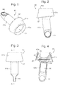
- the present invention provides an irradiation device for insertion into an orifice of the body to provide photodynamic therapy, the device comprising: a housing moulded from a resilient material and adapted to be fully inserted and secured in the orifice, the housing enclosing an LED lamp system and a power source for powering the LED lamp system; wherein the device is independently operational while located in the orifice; characterised in that: the housing comprises a first housing part for holding the power source and a second housing part for holding the LED lamp system, the first and second housing parts being separable and preferably being formed separately from the LED lamp system; and in that the first housing part consists of a chamber for holding the power source and an opening into the chamber is provided through a resilient opening part, wherein the chamber is closed when the first housing part is joined to the second housing part.
- the term "irradiation device” means a device which is a light source, i.e. provides light or illumination or radiation in the form of light but no ionizing radiation such as x-rays or gamma rays.
- illumination i.e. provides light or illumination or radiation in the form of light but no ionizing radiation such as x-rays or gamma rays.
- illumination i.e. provides light or illumination or radiation in the form of light but no ionizing radiation such as x-rays or gamma rays.
- the device of WO 2010/078929 has a housing that is moulded in a single piece enclosing the power source and LED lamp system. This has advantages in relation to the sealing of the device.
- the inventors have found that with the arrangement of WO 2010/078929 automated manufacturing is difficult and handling of the power source and LED lamp system during manufacturing requires a high degree of manual labour. Hence specifically trained personnel is needed to assemble the device which results in high costs per unit.
- the use of a two-part housing simplifies the manufacturing process since it is possible to create an automated system for inserting the power source and joining the two parts of the housing.
- the two housing parts are assembled around and then enclose the power source and LED lamp system.
- the reduction in the amount of manual labour required leads to significant advantages in relation to the cost per unit and the time taken to manufacture each unit, both of which are greatly reduced.
- the present invention provides a method of manufacturing an irradiation device for insertion into an orifice of the body to provide photodynamic therapy, the device comprising: a housing adapted to be fully inserted and secured in the orifice, the housing enclosing an LED lamp system and a power source for powering the LED lamp system; wherein the device is independently operational while located in the orifice; the method comprising: moulding a first housing part from a resilient material and moulding a second housing part from a resilient material, wherein the first housing part consists of a chamber for holding the power source and an opening into the chamber is provided through a resilient opening part, and the second housing part is for holding the LED lamp system, the first and second housing parts being separate mouldings and preferably being formed separately from the LED lamp system; and the method further comprising: closing the chamber by joining the first housing part to the second housing part in order to form the housing of the device.
- the first and second housing parts are separable in that they are formed as two separate parts. They may be made as completely separate mouldings, or it may be possible to use a single moulding for both parts and then cut the two apart after moulding is completed.
- the first and second housing parts may be permanently or semi-permanently joined together during the manufacturing process. Advantages of the above aspects arise from the use of two parts that are separated during manufacture and brought together to seal the housing about the LED lamp system and power source.
- the resilient opening part advantageously allows for an electrical coupling to pass from the power source to the LED lamp system.
- the resilience of the opening enables the electrical coupling to be easily assembled with the first housing part of the device.
- the resilient opening can be deformed to insert and/or remove the power source into or from the first housing part.
- the resilience of the resilient opening part may be such that it can be stretched open to a sufficient degree to allow the power source to be pushed through. Once the power source is within the first part then it is securely held in place by the resilient opening part, which returns elastically to its original, unstretched, configuration.
- the device may include a battery cap to provide an opening into the first housing part, for example a cap at an opposite end of the first housing part to the resilient opening part.
- the battery cap may have a bayonet, screw or clip fitting to hold it in place once the battery has been inserted.
- the resilient opening part preferably comprises a neck part for holding the power source within the chamber.
- the neck part may be arranged to enclose a part of the width of the power source when it is within the chamber.
- the neck part is preferably a resilient narrowing of the entrance to the chamber to a size less than the width of the power source to thereby hold the power source within the chamber.
- the neck part may form one or more shoulders across the end of the chamber.
- the neck part has a slot shaped opening with resilient material at either side of the length of the slot forming two shoulders across the end of the chamber. This shape allows for deformation of the neck part to occur to insert the power source and/or electrical coupling without the need for significant stretching of the resilient material.
- the shape of the neck part may also allow for bending of the first housing part at the neck, enabling the chamber to flex relative to the outer of the opening part and the second housing part.
- This can improve patient comfort and may, for example, allow for good fit for variations in the position of the cervix, e.g. posterior cervix.
- the slot of the neck part has an internal opening with a width of 8 mm or more, preferably about 10 mm or more.
- the chamber should be of sufficient size to hold the power source, and this may be with or without stretching of the resilient material that forms the walls of the chamber.
- the chamber is sized to fit tightly around the power source, for example chamber may have dimensions the same as or slightly smaller than the dimensions of the power source. This ensures that the power source is securely held by the elasticity of the resilient material during use of the device and minimises the risk of damage to the electrical connections occurring due to movement of the power source.
- the chamber comprises a separate holder or cradle to hold the power source and optionally also required electrical connections or couplings for the power source.
- the electrical coupling from the power source to the LED lamp system preferably passes through the neck part.
- a wire or other electrical connector extending from the power source to electrical connections at the LED lamp system.
- the power source is electrically connected to the LED lamp system whilst the first and second part of the housing are separated from one another. This simplifies the manufacturing process.
- the opening part of the first housing part may be arranged to provide a cavity for holding the excess length of the electrical connector (for example a coil of wire) that may be required to allow for the preferred sequence of manufacturing steps.
- the power source preferably comprises one or more batteries.
- Suitable batteries include lithium batteries or equivalent of sufficient capacity which may also be stored for up to 10 years. For example a 1/2 AA size LiMnO 2 battery may be used. The slow loss of charge and small size of lithium ion batteries makes them particularly suited for use as the power supply for the device.
- the power source is sealed within the housing.
- sealed it is meant that the housing is fluid tight in use to prevent fluids leaking into or out of the device.
- the seal can be attained by a tight join between the first and second housing parts.
- a sealing media may be used at the joint between the first and second housing parts, such as an adhesive, gel or semi-solid sealant.
- the resilient material is silicone, non-cured silicone may be used to seal the joint between the first and second housing parts.
- Another way to achieve a tight join between the first and second housing parts is vulcanization. Such a tight join is preferred not only for fluid tightness, but also for gas tightness, i.e. it also allows the use of ethylene oxide for sterilization of the device.
- the opening part on the first housing part has a coupling part to join to and form a seal with a complementary shaped coupling part on the second housing part, for example by plug and socket arrangement, by elastic and/or friction fit.
- alignment markers are present on each of the housing parts, e.g. on the outside of the opening part of the first housing part and the outside of the complementary shaped coupling part, which need to be aligned when the housing parts are joined together to ensure the correct position of one housing parts to each other.
- the material of the housing may be selected for its ability to form a secure seal when two parts made of the material are in engagement.
- One of the two coupling parts may be stretched to place it around the other of the two coupling parts, thereby using the elasticity of the resilient material to hold the two housing parts together. When the two coupling parts are joined this closes the chamber and forms the complete housing by connection of the first and second housing parts.
- the resilient material used to mould the housing parts can be any resilient material commonly used in medical devices; for example rubber, latex, silicone or other natural, semisynthetic or synthetic polymers or copolymers, preferably silicone.
- a part or all of the resilient material of the second housing part which holds the LED lamp system is at least partially transparent.
- the same resilient material is used to mould the first and second housing part, with the resilient material of the second housing part being at least partially transparent and with the resilient material of the first housing part being opaque.
- silicone is used to mould the first and second housing part wherein the silicone which is used to mould the first housing part contains pigments which makes it opaque to the light emitted by the LED lamp system.
- the second housing part holds the LED lamp system it is preferred for the light for the photodynamic treatment to exit via a treatment surface on the second housing part and to be directed to a treatment area on the patient and wherein the treatment surface preferably has a size and/or shape adapted for complementary fit with said treatment area. It is therefore particularly preferred for the second housing part to be moulded of a material that is at least partially transparent. Transparency in the current context should be understood to mean transparency in relation to the light emitted by the LED lamp system, or at least those wavelengths of the light that are required to excite the photosensitiser, i.e. to perform the photodynamic treatment of the patient.
- the LED lamp system is formed separate from the moulding of the second housing part. Hence, preferably, the LED lamp system is not encased or attached to the second housing part during the moulding process.
- the LED lamp system may include one or more of the LEDs, connecting circuitry, a control mechanism and a substrate such as board of a printed circuit board, for example. It is advantageous for the LED lamp system to be provided separate from the moulding during manufacture since this makes the process more straightforward to automate.
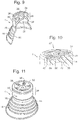
- the second housing part has one or more moulded cavity to fit elements of the LED lamp system.
- the LED lamp system may comprise a circuit on a substrate with LEDs and other circuit elements protruding from a circuit board.
- the second housing part may have cavities for holding the circuit elements.
- the LED lamp system can be securely fitted in a known orientation relative to the second housing thereby ensure that the device can be manufactured with consistent light output characteristics.
- one or more moulded cavity especially one or more moulded cavity which results in a tight fit between the LEDs of the LED lamp system and said cavities, efficient heat dissipation is achieved.
- the second housing part includes a treatment surface, as described below, then the one or more moulded cavity preferably act(s) to direct light from the LED lamp system through the material of the second housing part to the treatment surface.
- the one or more moulded cavity may be enclosed by a fastening lip for securing elements of the LED lamp system within the cavity.
- the fastening lip may be a lip extending inwardly about all or a part of the circumference of the one or more moulded cavity. Since the housing part is moulded from a resilient material then the fastening lip can be deformed resiliently to allow insertion of the LED lamp system.
- the one or more moulded cavity and the fastening lip are arranged to guide the LED lamp system into the correct position when the LED lamp system is pushed into the one or more moulded cavity. This increases ease of manufacture.
- the device of the current invention is adapted to be fully inserted and secured in the orifice and does not require connection to an external power supply or light source during operation.
- independently operable it is meant that the device can provide illumination for PDT without concurrent connection to any external device.
- the device is hence fully self-contained and forms an enclosed unit including both the light source and the power supply required for photodynamic procedures.
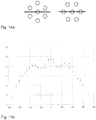
- PDT is preferably carried out at very low mean irradiance, i.e. average irradiance of all LEDs the LED lamp system is comprised of.
- Irradiance refers to the radiant power incident on a unit area (seen from the light source, in contrast to fluence rate which is seen from the object/area that is illuminated) and is measured in units of W/cm 2 .
- PDT carried out with illumination with low mean irradiances e.g. 10 mW/cm 2
- illumination using low irradiances is known to strongly reduce the patient discomfort (pain) during illumination, and, if precursors like ALA or derivatives of ALA are used, may also improve the PDT effect by allowing a continuous build-up of endogenous porphyrins (from said precursors) and to prevent oxygen depletion during illumination ( S. Jacques et al., "PDT with ALA/PPIX is enhanced by prolonged light exposure putatively by targeting mitochondria", SPIE Proceedings Vol. 2972, "Optical Methods for Tumor Treatment and Detection", ed. T.
- the device according to the invention provides, in use, preferably a mean irradiance below 50 mW/cm 2 , for example mean irradiance in the range of 0.5 to 40 mW/cm 2 , preferably below 30 mW/cm 2 , more preferably in the range of 2 to 20 mW/cm 2 and most preferably in the range of 5 to 10 mW/cm 2 , e.g. 5 to 6 mW/cm 2 , 6 to 7 mW/cm 2 and most preferred 7 mW/cm 2 to 8 mW/cm 2 .
- the device is therefore not only more "patient friendly", it can also increase the efficacy of the treatment.
- the shape of the housing can vary, but is generally designed so that it comfortably fits within the orifice and remains in place independent of the patient's physical activity.
- suitable shapes for the outer portion of the housing can for example be similar to the shapes of some contraceptive devices used to prevent pregnancy, such as FemCap® and other similar devices intended for blocking sperm from entering the uterus.
- other suitable shapes and structures can be utilised, for example based on shapes known for use as suppositories and/or pharmaceutical pessaries.
- the present invention has been created with the treatment of human patients in mind, it is also possible for the device to be used in the treatment of other animals. Therefore the shape of the housing will be dependent on the orifice where treatment is required and on the anatomical structure of the animal on which the device is intended for use.
- the device can comprise a slim housing, which the walls of the orifice will envelope and hold in place.
- the housing may, for example, be similar in size and shape to a tampon.
- the outer surface of the housing may be textured to improve the grip of the device.
- a textured surface can also be of benefit in providing a surface for the delivery of drugs, e.g. PDT drugs, to the area of the body that requires treatment.
- devices of different sizes and/or shapes may be made available.
- devices of three size may be provided for (i) patients that have not been pregnant, (ii) patients that have had a pregnancy but not carried to term and (iii) patients who have given birth.
- the housing preferably comprises a flexible outer portion that can adjust its shape to form a secure fit with the vaginal walls and enables the device to be used within many different shapes and sizes of vagina.
- the flexible outer portion also helps to decrease the risk of slipping or misalignment of the device over an extended treatment period, during which the patient may be physically active.
- a similar outer portion may be used for a device intended for insertion in other orifices, if required.
- the flexible outer portion is formed on the second housing part.
- the flexible outer portion is advantageously formed from the resilient material.
- an expandable material could be used such that, after insertion, the outer portion of the housing expands to firmly grip the walls of the orifice. The expansion could be initiated through body heat, exposure to fluid, removal from a delivery device/instrument etc.
- Forming the flexible outer portion from a resilient material enables the shape of the flexible portion to be altered while also providing a biasing outwards force to hold the device in place.
- the outer diameter of the outer portion is preferably sized so that it must be reduced in order to insert the device into the orifice. The outer portion will then provide an outwards force toward the walls of the orifice.
- the flexible outer portion can be any shape which is capable of creating a secure fit with the walls of the orifice.
- the flexible outer portion may be provided in the form of a number of discrete legs, ridges or other protrusions radially and/or longitudinally spaced about and extending outward from the housing.
- the flexible outer portion may form a continuous outer surface of the housing. This surface could either form the whole or a part of the exterior of the housing.
- the outer portion may be a disk or cup-shaped section found at either the front or rear of the device, or a covering which extends over the entire length of the housing.
- the flexible outer portion forms a continuous surface which tapers outwards towards the rear end of the device i.e. the end of the device which, in use, is closest to the entrance of the orifice.
- the outer portion can be approximately frustoconical in shape.
- the flexible outer portion may have a different configuration when in use to the configuration when formed during moulding. This can make the moulding process simpler by simplifying the shape of the moulding. It also allows for the flexible outer portion to have change configuration when it is inserted or removed from the body orifice, which can be more comfortable for the patient.
- the second housing part is moulded with a flexible outer portion having a continuous surface as described above that, in the as-moulded configuration tapers outward toward the front end of the device, and which is arranged to fold elastically into a second stable configuration where the flexible outer portion is reverse and folds back on itself so that it tapers outward toward the rear end of the device. This allows the flexible outer portion to be fitted securely into the orifice during use, and also allows removal from the orifice to be more comfortable for the patient since the flexible outer portion can return to its as-moulded configuration as the device is removed.
- the device For insertion into the ear or nose the device may be shaped based on known designs for ear or nose plugs.
- the housing comprises a treatment surface, the LED lamp system being arranged to emit light from the treatment surface.
- the treatment surface is preferably on the second housing part.
- the device can be arranged to provide irradiation to the walls of the orifice, in which case the treatment surface may be an outer circumferential surface of the housing.
- the treatment surface preferably has a size and or shape selected for complementary fit with the treatment area, and is preferably sized to confront the entire area where PDT is required.
- the LED lamp system and treatment surface are preferably arranged such that light is emitted toward the treatment area at sufficient proximity to achieve the desired treatment effect.
- the device may be arranged to provide irradiation to a particular area of the inside of the orifice.
- the treatment surface may be arranged to direct and/or focus light onto a particular treatment area of the inside of the orifice when the device is in use.
- the device is adapted for use in PDT of the cervix, i.e. the cervix is the treatment area of interest. Therefore, the treatment surface is preferably shaped so as to cover, in use, the external opening of the cervix. When the device is correctly inserted into the vagina the treatment surface will cover the opening of the cervix and hence enable the emitted light to irradiate the cervical area.
- the size of this treatment surface should be such that it fits over the entire portion of the cervix, for example it may be 20-50 mm in diameter, more preferably 20-35 mm in diameter and most preferably 22-30 mm in diameter.
- the treatment surface may be fully transparent to light having the wavelengths required for PDT treatment and being emitted by the LED lamp system.
- the treatment surface is at least partially transparent.
- the material of the treatment surface and/or other material between the treatment surface and the light emitting portion(s) of the LED lamp system is arranged to diffuse the light, thereby enabling an even distribution of light from the LEDs.
- a transparent material is used to form the second housing part such that the treatment surface is fully transparent.
- a transparent material is used to form the treatment surface while a non (fully) transparent material is used to form the second housing part.
- the second housing is made from a single material which is at least partially transparent.
- an at least partially transparent silicone is used as a material for the second housing part.
- the LED lamp system may be positioned on or extend out of the treatment surface. In such embodiments it is not necessary for the light to pass through the treatment surface and hence no constraints are placed on its opacity. However, in a preferred embodiment the LED lamp system is positioned below the treatment surface.
- the treatment surface is concave. This can assist in directing the emitted light towards a convex treatment area, such as the cervix.
- the device may comprise a protrusion that extends outwardly of the device from the treatment surface.
- this protrusion forms a cylindrical tube. This can be used both to assist in the correct positioning of the device within the vagina and also to direct light to the cervical canal. In the latter case the tube acts as a light tube.
- the flexible outer portion is located to the rear of the treatment surface. This prevents any interference with the light treatment.
- the outer portion is a continuous surface the outer portion can extend from the treatment surface towards to rear of the device, tapering outwards such that the widest section of the outer portion is, in use, located rearwards of the treatment surface.
- the LED lamp system may comprise one LED or preferably an array of LEDs.
- a particularly preferred LED array for PCT of cervix comprises 3-15 LEDs, more preferably 7 LEDs.
- the term "LED” is intended to cover any form of light emitting diode, for example OLEDs (organic light emitting diode), quantum dot LEDs or LECs (light emitting electrochemical cells, as described in A. Sandström et al., Nat. Commun. 3, 2012, 1002 ).
- the energy consumption per unit time of the LED lamp system should be such that the heating of tissue of the treatment area does not result in undue discomfort or damage to the patient.
- the light will in general be applied at a dose of 10-200 J/cm 2 , for example at 20 to 150 J/cm 2 , preferably 30 to 140 J/cm 2 , optionally 30 to 100 J/cm 2 , and more preferably 100 to 130 J/cm 2 , e.g. 37 J/cm 2 or 40 J/cm 2 or 125 J/cm 2 , and this light dose is preferably provided at a low mean irradiance over several hours, as discussed earlier.
- the device according to the invention when used for providing PDT to the cervix, provides light at a mean irradiance of about 6-8 mW/cm 2 , preferably of a about 7 mW/cm 2 over a period of 4 to 6 hours, preferably 4 to 5 hours thus delivering a light dose of about 85 to 175 J/cm 2 .
- the wavelength of light used for the PDT is selected to excite the photosensitiser and hence the LEDs are selected for their ability to emit wavelengths of light suitable for this effect.
- the LEDs emit, in use, light having wavelengths in the range of 300-800 nm, for example, the range 500-700 nm has been found to be particularly effective.
- the at least one LED emits, in use, light having wavelengths in the range of 630-690 nm, most preferably light having a wavelength of 635 ⁇ 5 nm.
- a composition comprising a photosensitiser precursor selected from 5-aminolevulinic acid or a derivative, e.g. an ester thereof, red light (600 - 670 nm) is used since light at this wavelength is known to penetrate well into tissue.
- the LED lamp system comprises filters to ensure that only light within a certain wavelength range, such as those mentioned above, is emitted from the device.
- the treatment surface may be designed such that only light having these preferred wavelengths is transmitted.
- the LED lamp system may simply comprise electrical connections for the power supply and one or more LEDs. With this arrangement, immediately prior to insertion of the device the lamp system would be activated to switch on the one or more LEDs. The device would then be inserted into the orifice where the LED(s) will illuminate the treatment area until the device is removed, the power supply is depleted or the preprogrammed illumination time has elapsed.
- Activation of the LED lamp system may be triggered by a switch.
- the switch is preferably enclosed within the housing when the two housing parts are joined and arranged to be operated whilst sealed within the housing.
- the switch may be a mechanical switch located beneath e.g. a flexible part of the housing, with operation of the switch being permitted by the resilience of the flexible part.
- the switch may be operated by means of an electrical or magnetic field transmitted through the housing.
- a magnetically operated switch may be implemented by the use of a magnet outside the housing, preferably a magnet which is part of the packaging of the device, to hold a 'normally closed' reed switch, preferably a read switch comprised in a holder or cradle for the power source, open.
- a magnet outside the housing
- a 'normally closed' reed switch preferably a read switch comprised in a holder or cradle for the power source, open.
- the reed switch will close and this can be used to activate the device.
- the device In a simple system using just a power source and a LED lamp system it is hard to control the light dose which is delivered when the device is in use, as the precise life and power output of the power source will vary. In addition the light provided by the LED lamp system will be constant. In order to avoid unacceptable heating of tissue of the treatment area, light at low irradiance is preferably used. It may also be beneficial for the device to be able to provide pulsed light.
- the LED lamp system further comprises a control circuit, such as a microcontroller or microprocessor, for regulating the light provided by the at least one LED.
- the control circuit of the LED lamp system may be activated by a switch as described above.
- the control circuit comprises a timer.
- the LED lamp system can then be programmed to begin illumination at a pre-determined time interval after activation. This ensures that sufficient time has passed from activation to the start of illumination. For example, in order to allow the uptake of a photosensitiser or precursor into the target cells or build up of the photosensitser from a precursor/conversion of a precursor into a photosensitiser (e.g.
- the device may repeat the illumination (re-PDT) after a certain period of time, e.g. 3 hours.
- control circuit may be arranged to provide pulsed illumination. This can be achieved by providing a function generator within a microprocessor. As mentioned above, pulsed light is advantageous in ensuring that no unacceptable heating of tissue occurs. In addition, providing intervals in illumination enhances tissue oxygenation and the effect of PDT. Further it allows for the re-accumulation of intracellular photosensitisers from precursors in surviving cells that can be treated with repeated illuminations. The frequency and length of the pulses can be chosen according to the requirements of the treatment regime and set within the control circuit.
- control circuit can be programmed by the user. This enables the length, strength and illumination pattern to be adjusted to suit individual treatments. Suitable re-writable memory forms include EPROM, EEPROM, flash etc. However, the control circuit memory is preferably read only (ROM) and programmed at the time of manufacture.
- Access to the control circuit could be achieved by means of a user interface on the device.
- the interface may be integral with the device. Thus, it may comprise small buttons that may be pressed with a suitable tool or reed switches. Each button or switch may activate a given pre-set condition such as light dose, intensity, pulsed/steady light, etc.
- the control circuit should preferably be sealed within the housing.
- the LED(s) could be positioned such that these protrude from the housing.
- the LED lamp system is entirely sealed within the housing during use.
- the user interface may be accessible through e.g. a flexible area of the housing.
- the housing may comprise a sealable opening which provides access to the interface.
- control circuit may comprise a receiver for connection to a remote terminal.
- specific program commands can be communicated from the remote terminal, e.g. a computer, to the control circuit.
- the receiver may comprise an input port adapted for connection to a cable.
- the input port is suitably shaped to receive, for example, a USB or other male connector.
- the input port must be sealed during use. Therefore the housing may comprise a plug for insertion into the port.
- the program commands may be transmitted to the device by means of a wireless connection.
- the receiver may be an infra-red or radio wave receiver or bluetooth. This has the advantage that a physical input port is not necessary and instead the control circuit can be permanently sealed within the housing.
- control circuit further comprises a feedback system. This enables the control circuit to make adjustments in the treatment program to account for deviations in expected LED performance.
- the feedback system may comprise a light monitor or other direct or indirect monitor to measure the light dose that has been given to the patient.
- the control circuit may be programmed to switch off the LED(s) after a pre-determined light dose has been delivered rather than a pre-determined time.
- a dosimeter may override the timer in the event that the LEDs do not operate as expected. For example, if the power supply is faulty the output of the LEDs may be reduced. Therefore it will be necessary to continue illumination beyond the pre-determined time in order to provide the complete light dose. Conversely if the power output of the LEDs is stronger than anticipated the illumination can be stopped ahead of the pre-determined time interval, or the duration of each pulse can be shortened to prevent overheating of tissue.
- the control circuit may further comprise a temperature sensor which allows illumination with high irradiances, e.g. irradiances above 50 mW/cm2, until the target tissue reaches a certain temperature, e.g. 40-43 °C. When said temperature is reached, the illumination stops until the temperature of the target tissue decreases, e.g. to 37-38 °C. At this temperature, illumination is switched on again.
- a temperature sensor which allows illumination with high irradiances, e.g. irradiances above 50 mW/cm2, until the target tissue reaches a certain temperature, e.g. 40-43 °C. When said temperature is reached, the illumination stops until the temperature of the target tissue decreases, e.g. to 37-38 °C. At this temperature, illumination is switched on again.
- the control circuit may further comprise a proximity sensor which measures the distance between the treatment surface and the treatment area on the patient and thereby detects misplacement or misfits. In such instances, the illumination is either paused or the device is not activated at all. An appropriate feedback is given to the user.
- a proximity sensor can also work as an on/off switch for the device.
- control circuit may be arranged to provide a signal to the user when treatment is complete to indicate that the device can be removed.
- a signal may be provided, such as an alarm sound and/or a light signal.
- a vibration could be used as the signal to indicate the end of the treatment.
- the patient would be informed of the length of the treatment and so the signal can be used to confirm an expected end of the treatment and hence need not be overly intrusive.
- the user can use an app, e.g. on his/her mobile phone, tablet or computer to get the aforementioned information.
- control circuit may be used to turn off the LEDs at the end of the treatment there is no great ill effect for the patient if the device remains inserted for longer than the treatment time. However, it is expected that patients will wish to know when treatment has ended and the device can be removed.
- control circuit Preferably some or all of the above mentioned features of the control circuit are contained in a microprocessor.
- the device may comprise a lens system arranged to provide homogenous illumination over the treatment area.
- the treatment surface and/or material of the housing adjacent thereto may act as the lens system.
- this surface may be formed of silicone or another material comprising surface elements for diffusing the light emitted by the LED(s).
- the device In use the device is preferably placed into the orifice by a doctor, a nurse or another person with experience or education within relevant fields. However, patients might in some situations choose to insert the device themselves.
- the device comprises a handle at its rear end.
- the handle can be used by the patient or medical practitioner to firmly grip the device during insertion and removal.
- the chamber for the power source may additionally act as the handle for the device.
- the device comprises an attachment point for a removal cord, for example a hole or eye.
- a removal cord may be attached to the device for use in pulling the device out of the orifice.
- the device is placed (and removed) using a specific instrument, such as a pair of tweezers.
- the device is designed for a single-use and for disposal after that single use.
- the device includes one or more features that promote single-use and/or prevent repeat use.
- the power source may be arranged to provide power that is only sufficient for a single-use, i.e. such that the power source is depleted after the required treatment is complete.
- the power source may be arranged so as not to be recharged, and/or the control circuit may lack access to re-charge the power source.
- the control circuit may be arranged to prevent re-use by means of features of its programming and/or it may include a deactivation mechanism that destroys circuitry or software when triggered.
- the control circuit may also be arranged to selectively deactivate if interference is detected.
- the device can be used to provide PDT according to the following method.
- a composition comprising a photosensitiser or precursor thereof (hereinafter "composition") is applied to the area to be treated or the area of interest is treated by means of a systematically acting composition.
- a systematically acting composition may be supplied intravenously or orally, for example.
- the composition may be applied by a physician, where applicable by using a specialised applicator, or alternatively it may be applied by means of a drug delivery system on the device, for example as discussed below.
- the device is activated and inserted.
- the patients can then immediately leave the medical facility and continue their normal daily routine while the treatment area is receiving illumination from the device. In this way treatment can occur over a prolonged period of time without inconvenience to the patient.
- After the treatment is complete the patients can either return to the medical institution for removal of the device or remove it themselves.
- the device can either be discarded or returned to the medical institution for disposal.
- the device of the present invention further comprises a drug delivery system.
- the drug delivery system may comprise a drug carrying area on the housing, preferably a drug carrying area on a treatment surface. This might be a textured surface for carrying a composition of photosensitiser or precursor or the treatment surface itself without any further modifications may act as the drug carrying area.
- the drug delivery system may comprise a reservoir for housing a composition comprising a photosensitiser or precursor thereof (hereinafter "composition").
- a significant advantage of this is that the patient need not wait at the hospital for several hours between application of the composition and illumination, as is normal in existing PDT procedures.
- the device may automatically perform the illumination either immediately upon application or preferably at a later time.
- only one invasive procedure is required.
- the drug delivery system further comprises a physical, mechanical or electrical system related to delivery.
- a physical, mechanical or electrical system related to delivery may include, for example, filters, membranes, one or more reservoirs arranged to deliver the composition based upon a preset plan or based on physical conditions, such as for example pH, osmolality, temperature, pressure, water content in the surroundings.
- the most preferred drug delivery system is just a single drug carrying area for carrying the composition, and in a most preferred embodiment, the drug carrying area is the treatment surface itself.
- the method of use is similar to that described above except that the composition is not applied to the treatment area in a separate procedure. Instead the composition is applied to the drug carrying area, e.g. the treatment surface, and is hence applied to the treatment area on the body of the patient upon insertion of the device into the orifice. Illumination is then conducted as described above.
- the composition is not applied to the treatment area in a separate procedure. Instead the composition is applied to the drug carrying area, e.g. the treatment surface, and is hence applied to the treatment area on the body of the patient upon insertion of the device into the orifice. Illumination is then conducted as described above.
- the composition can be supplied together with the device (i.e. a pre-filled device), preferably in such a way as described in WO 2012/004399 .
- the drug delivery system i.e. drug carrying area or reservoir, preferably treatment surface
- the cover such as a foil or cap
- the device can be supplied separately from the composition. This enables the physician to choose the optimal composition for a particular case and add this to the drug delivery system, i.e. drug carrying area or reservoir, preferably treatment surface, prior to insertion.
- composition to be used with the device may comprise any suitable photosensitiser or precursor of a photosensitiser.
- a range of photosensitisers are known in the art.
- one type of such compounds are compounds that per se are phototoxic to target cells or species or have light emitting properties when exposed to light. Such compounds have relatively large molecular weights and are often complex molecules.
- Typical photosensitisers include dyes like hypericin and PVP hypericin, psoralens, porphyrins such as hematoporphyrins, protoporphyrins, uroporphyrins, coproporphyrins, benzoporphyrins or deuteroporphyrins, in particular Photofrin® (profimer sodium), photosan III or verteporfin; chlorins, including bacteriochlorins and isochlorins such as chlorine e6, talaporfin or temoporfin and phthalocyanines such as aluminium- and silicon phthalocyanines.
- photosensitisers are compounds that not per se are toxic or light emitting, but form photosensitisers in vivo.
- Such compounds - referred to herein as precursors - are typically 5-aminolevulinic acid (5-ALA) and derivatives of 5-ALA, like 5-ALA esters.
- a composition comprising either type of compound can be used or supplied with the present device.
- 5-aminolevulinic acid 5-ALA
- 5-aminolevulinic acid 5-ALA
- PpIX protoporphyrin IX
- Singlet oxygen is extremely reactive and reacts fast with various cellular biomolecules resulting in cell death.
- 5-ALA and its derivatives are widely known and used in methods of photodynamic therapy (PDT) for the treatment of various abnormalities or disorders of the skin or other epithelial organs or mucosa, especially cancers or pre-cancerous lesions, as well as certain non-malignant lesions, e.g. skin diseases such as actinic keratosis (AK) and acne.
- PDT photodynamic therapy
- 5-ALA Levulan®, Dusa
- 5-ALA methyl ester Metalvix®, Galderma, Switzerland
- 5-ALA and derivatives thereof e.g. 5-ALA esters in PDT is well known in the scientific and patent literature (see, for example, WO 2005/092838 , WO 02/09690 , WO 02/10120 and WO 96/28412 ) and all such compounds and their pharmaceutically acceptable salts are suitable for use with the device herein described.
- Esters of 5-aminolevulinic acid and their pharmaceutically acceptable salts are preferred precursors in a composition for use with the invention, see, for example, WO 96/28412 and WO 02/10120 to Photocure ASA.
- Preferred examples of such precursors include those of formula (I) and pharmaceutically acceptable salts thereof: R 2 2 N-CH 2 COCH 2 -CH 2 CO-OR 1 (I) wherein
- alkyl includes any long or short chain, cyclic, straight-chained or branched saturated or unsaturated aliphatic hydrocarbon group.
- the unsaturated alkyl groups may be mono- or polyunsaturated and include both alkenyl and alkynyl groups. Unless stated otherwise, such alkyl groups may contain up to 40 carbon atoms. However, alkyl groups containing up to 30 carbon atoms, preferably up to 10, particularly preferably up to 8, especially preferably up to 6 carbon atoms are preferred.
- the R 1 groups are substituted or unsubstituted alkyl groups. If R 1 is a substituted alkyl group, one or more substituents are either attached to the alkyl group and/or interrupt the alkyl group. Suitable substituents that are attached to the alkyl group are those selected from: hydroxy, alkoxy, acyloxy, alkoxycarbonyloxy, amino, aryl, nitro, oxo, fluoro, -SR 3 , -NR 3 2 and -PR 3 2 , wherein R 3 is a hydrogen atom or a C 1-6 alkyl group. Suitable substituents that interrupted the alkyl group are those selected from: -O-, -NR 3 -, -S- or -PR 3 .
- R 1 is a substituted alkyl group
- one or more aryl substituents i.e. aryl groups, preferably one aryl group, are preferred.
- aryl group denotes an aromatic group which may or may not contain heteroatoms like nitrogen, oxygen or sulphur. Aryl groups which do not contain heteroatoms are preferred. Preferred aryl groups comprise up to 20 carbon atoms, more preferably up to 12 carbon atoms, for example, 10 or 6 carbon atoms. Preferred embodiments of aryl groups are phenyl and naphthyl, especially phenyl. Further, the aryl group may optionally be substituted by one or more, more preferably one or two, substituents. Preferably, the aryl group is substituted at the meta or para position, most preferably the para position. Suitable substituents include halo alkyl, e.g.
- alkoxy preferably alkoxy groups containing 1 to 6 carbon atoms, halo, e.g. iodo, bromo, chloro or fluoro, preferably chloro and fluoro, nitro and C 1-6 alkyl, preferably C 1-4 alkyl.
- Preferred C 1-6 alkyl groups include methyl, isopropyl and t-butyl, particularly methyl.
- Particularly preferred aryl substituents are chloro and nitro. However, still more preferably the aryl group is unsubstituted.
- R 1 is an unsubstituted alkyl group
- R 1 groups that are saturated straight-chained or branched alkyl groups are preferred.
- R 1 is a saturated straight-chained alkyl group
- C 1-10 straight-chained alkyl group are preferred.
- suitable straight-chained alkyl groups include methyl, ethyl, n-propyl, n-butyl, n-pentyl, n-hexyl and n-octyl.
- Particularly preferred are C 1-6 straight-chained alkyl group, most particularly preferred methyl and n-hexyl.
- R 1 is a saturated branched alkyl group, such branched alkyl groups preferably consists of a stem of 4 to 8, preferably 5 to 8 straight-chained carbon atoms which is branched by one or more C 1-6 alkyl groups, preferably C 1-2 alkyl groups.
- each R 2 independently represents a hydrogen atom or a group R 1 . Particularly preferred for use in the invention are those compounds of formula I in which at least one R 2 represents a hydrogen atom. In especially preferred compounds each R 2 represents a hydrogen atom.
- the most preferred precursors to be used in a composition together with the devices according to the invention are compounds of formula I and pharmaceutically acceptable salts thereof, wherein R 1 is C 1 -C 6 alkyl, e.g. hexyl, more preferably straight chain C 1 -C 6 alkyl, e.g. n-hexyl and both R 2 represent hydrogen, i.e. 5-ALA hexyl ester and pharmaceutically acceptable salts thereof, preferably the HCI salts.
- the most preferred precursor is 5-ALA hexyl ester and the most preferred pharmaceutically acceptable salt of 5-ALA hexyl ester is the HCI salt.
- compositions comprising the photosensitiser or precursor to be used together with the device of the invention can be any type of pharmaceutical formulation and may be prepared by any conventional procedure available in the art.
- Preferred compositions comprising systemically acting photosensitisers or precursors for oral or intravenous administration are liquids (aqueous and non-aqueous) or solids such as, tablets or pills.
- Preferred compositions comprising photosensitisers or precursors for local application are liquids (aqueous and non-aqueous), semi-solids such as lotions, creams, ointments, gels or pastes, foams or other expandable compositions (for example based on heating to body-temperature) and compositions comprised in patches.
- Semi-solid compositions such as described in WO 2010/142457 are preferred. Most preferred are semi-solid compositions, e.g. ointments comprising a precursor, preferably a precursor of formula (I).
- the components in the composition are the same components found in pharmaceutical products on the market, and a listing of such components can be found in handbooks of pharmaceutical excipients.
- the formulation is as such that the composition is well absorbed into the tissue of the treatment area or that it is transparent in order not to interfere with the illumination.
- the present invention provides a composition
- a composition comprising precursor of a photosensitiser which is 5-ALA or a derivative of 5-ALA or a pharmaceutically acceptable salt thereof for use in a method of photodynamic therapy of a treatment area on the cervix by means of the device described above, the method comprising: administration of the composition to the treatment area insertion of the device into the vagina such that the treatment surface is in complementary fit with the treatment area on the cervix; and illuminating the treatment area with light from the LED lamp system of the device.
- the method may include a step of selecting a device of suitable size and/or shape.
- the device may be selected firstly to suit the orifice concerned, and secondly to suit different patient conditions.
- a device for treatment of the cervix would preferably be selected from a range of sizes depending on the patient's history of pregnancy.
- the composition may be applied to the treatment area prior to insertion of the device, and this may be done by directly applying the composition, where applicable by using a suitable applicator.
- the composition may be applied systemically, if it contains a systemically acting photosensitiser or precursor.
- the composition is supplied via a drug delivery system of the device such that the steps of application of the composition and insertion of the device occur simultaneously.
- the drug delivery system may comprise a drug carrying area or reservoir or may simply be the treatment surface of the device, as discussed above.
- the light will in general be provided by the device at such mean irradiance over such periods and at such wavelengths as discussed above to deliver light doses as discussed above.
- the device can be provided separately from the composition or with the composition already contained within a drug delivery system.
- the device can be provided in the form of a kit comprising the device and at least one separate composition for use with the device, preferably a semi-solid composition comprising a photosensitiser or precursor which is provided in a suitable container, e.g. a tube or jar.
- the device can be used for providing PDT to a body orifice.
- the device is used for the photodynamic treatment of conditions, lesions, abnormalities and diseases of the female reproductive system, preferably the vagina and cervix.
- the device is used for the photodynamic treatment of HPV infections, intraepithelial neoplasia, dysplasia, precancerous lesions and cancer of the female reproductive system, preferably the vagina and cervix.
- the present device and method for photodynamic treatment may be combined with other therapeutic procedures, for example administration of other therapeutic drugs.
- These therapeutic drugs might be administered into the body prior to or together with placing the device in the orifice or might be administered through other routes of administration (e.g. oral, intravascular or dermal).
- routes of administration e.g. oral, intravascular or dermal.
- such drugs include hormones, antibacterial agents, antifungal agents, antiviral agents, anticancer agents or combination of such drugs.
- the prior art device of Figures 1 to 4 is an irradiation device 60 for photodynamic therapy of the cervix.
- Figures 1 to 3 show perspective, side and end views.
- Figure 4 is a cross-section along line A-A on Figure 3 .
- the device 60 is arranged for use in photodynamic treatment of the cervix and has a single part housing 61 including an upper housing portion 61a and a lower cylindrical housing portion 61b extending beneath the upper housing portion.
- the upper housing portion 61a is flexible and includes an outer portion 67 that is approximately frustoconical in shape and tapers outwards from the front end of the device 60 to the rear.
- the outer portion 67 is resilient such that, in use, this presses against the walls of the vagina in order to securely hold the device 60 in place.
- the shape of the upper housing portion 61a and its outer portion 67 can most clearly be seen in Figure 4 .
- An LED lamp system 62 is sealed within the upper housing 61a.
- the power supply for the lamp system is a battery 68 enclosed within the cylindrical housing portion 61b.
- the battery is a 1/2 AA size battery with the cylindrical housing portion 61b formed relatively tightly around it.
- the control circuit 69 is also enclosed with the battery, and advantageously this takes the form of a PCB with a diameter the same as the battery diameter, for efficient use of space.
- the front end of the upper housing 61a forms a treatment surface 63, which is a lens of transparent material covering the LEDs of the LED lamp system 62.
- This material is a transparent silicone which also forms the remainder of the flexible housing of the device 60.
- An opaque white silicone over-moulding is used to cover the sides of the upper housing portion 61a, both about the outer portion 67 and also on the sides within the outer portion 67, and to completely cover the cylindrical portion 61b. This white over-moulding acts as a reflector for the lens of the treatment surface, and hides internal parts in the cylindrical portion, which would include the battery 68 and control circuit 69.
- the treatment surface 63 is shaped so as to cover, in use, the opening of the cervix, thus ensuring that the illumination from the LEDs is directed on to the treatment area.
- Treatment surface 63 comprises a contact surface 63a, which typically has a diameter of 22 to 30 mm.
- the contact surface 63a acts as a drug delivery system, i.e. drug carrying area or reservoir, and hence carries a composition comprising a photosensitiser or a precursor.
- a loop 64 is provided at the base of the cylindrical housing portion 61b to facilitate insertion and removal of the device.
- a string can be attached to the loop 64, if required.
- FIG. 5 shows the outer features of the moulded housing, which is made up of a first housing part 2 and a second housing part 4.
- the two housing parts are moulded from a resilient material, for example a medical grade silicone material.
- the first housing part 2 consists of a chamber 6 for holding a power source and an opening part 8 enabling access to the chamber 6 and for joining to the second housing part 4.
- the chamber 6 is generally cylindrical in this embodiment, reflecting the shape of the power source that it encases.
- the opening part 8 has two main parts, being a neck part 10 at the end of the chamber 6 and a coupling part 12 extending away from the neck part 10.
- the second housing part 4 has a flexible outer portion 14 that, when moulded, forms a hollow frustoconical shape extending away from the first housing part 2 tapering outwardly away from the front of the device.
- the flexible outer portion 14 is folded back over the coupling part 12 of the first housing part 2 and hence forms a hollow frustoconical shape that tapers in the opposite direction, which would hence be tapering outwardly to the rear when the device is in use.
- the rearward direction is the direction away from the cervix, out of the body
- the front of the device is the end of the device that faces toward the cervix with the forward direction in this embodiment hence being the direction in which light is emitted.
- Circumferential ribs 16 provide strength for the flexible outer portion 14 and also aid in the folding movement of the flexible outer portion 14 as it changes from the as-moulded shape (shown in Figure 5 ) to the rearward tapering shape required for securing the device in the body.
- the first housing part 2 encloses a power source 41 in the form of a 1/2 AA sized lithium ion battery in the chamber 6.
- the battery 41 is held in an appropriate cradle 20, which also incorporates the required electrical connections for the battery 41.
- the chamber 6 is has a shape and size that is complementary to the shape and size of the battery 41 and cradle 20 and hence holds them tightly.
- the cradle may comprise a reed switch and an element such as a pin and the chamber 6 may comprise a notch (not shown). The notch will receive the pin and thus prevent a rotation of the cradle, i.e. rotation of the reed switch.
- the packaging of the device includes a magnet and where it needs to be ensured that the reed switch is held open while the device is inside the packaging.
- the chamber 6 may be moulded with a shape and size slightly smaller than the shape and size of the battery 41 and cradle 20 so that it is stretched around them via the resilience of the material of the first housing part 2.
- the battery 41 is electrically coupled to an LED lamp system 22 that is held on the second housing part 4.
- the LED lamp system 22 consists of LEDs 45 and a control circuit (described below with reference to Figure 11 ) moulded on a circuit board 24.
- the electrical coupling for the LED lamp system 22 passes through the neck part 10, the details of which can be more clearly seen with reference to Figures 7 and 8 .
- the neck part 10 has inner shoulders formed across the opening of the chamber 6 and outer shoulders across the width of the coupling part 12.
- the shoulders form a slot shaped hole 26, which is shown in transverse cross-section in Figure 6.
- Figures 7 and 8 show one half of the slot shaped hole 26 with the first housing part 2 shown empty, omitting the battery 41 and cradle 20.
- the battery 41 and cradle 20 are inserted by deforming the resilient material of the first housing part 2 to stretch open the slot 26.
- the neck part 10 When the battery 41 and cradle 20 are fully within the chamber 6 then the neck part 10 is allowed to return to its normal shape and the shoulders either side of the slot 26 hence hold the battery 41 and cradle 20 in place.
- the shape of the neck 10 also allows for the chamber 6 to bend along the line of the slot 26 so that it can move easily relative to the coupling part 12 and hence relative to the second housing part 4. This means that the device can deform whilst it is in use, making it more comfortable for the patient.
- Figures 7 and 8 also show the shape and form of the coupling part 12 effectively.
- the coupling part 12 since the device has a generally circular geometry for the second housing part 4, the coupling part 12 has a circular tube shaped section for joining to the second housing part 4.
- This circular tube section is attached to the outer shoulders of the neck part 10 by an asymmetric flange arrangement.
- the purpose of this is to make an angle between a central axis of the second housing part 4 and a central axis of the chamber 6 and battery 41 so that the device fits more comfortably within the body when in place for treatment of the cervix.
- the first housing part 2 is moulded from a resilient material, preferably silicone.
- the first housing part 2 is moulded from opaque silicone, i.e. the coupling part which will enclose the opening part 8 of the second housing part 4, once both housing parts 2 and 4 are joined together, is opaque to the light emitted by the LED lamp system 22, when the device is in use. In that way it is ensured that light emitted by the LED lamp system 22 only is emitted through the treatment surface 36 onto the cervix but not sideways onto the walls of the vagina.
- Figure 9 shows the second housing part 4 which consists of the flexible outer portion 14 described above and a body and lens section 28.
- the first housing part 2 connects to the second housing part 4 via the coupling part 12 of the first housing part 2 and a corresponding coupling part 30 on the second housing part 4.
- the coupling part 30 on the second housing part 4 is formed by the outer surface of the body and lens section 28, which has a cylindrical exterior.
- the two housing parts 2, 4 are joined by fitting the coupling part 12 of the first housing part 2 about the coupling part 30 on the second housing part 4.
- the resilient material of the coupling part 12 of the first housing part 2 can be stretched around the coupling part 30 on the second housing part 4 and will hence seal the device and securely hold the two housing parts 2, 4 together.
- the resilient fitting of the two coupling parts 12, 30 and the friction therebetween can be sufficient to keep the two housing parts 2, 4 together during use and form a fluid-tight seal.
- a sealing and joining media such as an adhesive can be applied to ensure that the two housing parts 2, 4 cannot be separated during use of the device.
- the chamber 6 When in use the chamber 6 can be gripped to hold and manoeuvre the device and in addition a hole 32 though the rearward end of the chamber 6 allows for a cord to be attached to make it easier to remove the device from the body. Since the device will be pulled by the cord it is important to ensure that the first and second housing parts 2, 4 are securely attached together. When the device is removed in this way the flexible outer portion 14 of the second housing part 4 may unfold from its rearward tapering position to resume its as-moulded position. This would mean that the taper now faces forward, into the body cavity, resulting in a more comfortable and easier removal of the device.
- Figures 9 and 10 illustrate the second housing part 4 and LED lamp system 22 in more detail in a perspective section view of the moulded housing part 4 alone and in a close up perspective section view of the body and lens section 28 with the LED lamp system 22 installed.
- the skirt-like flexible outer portion 14 has been described above.
- the body and lens section 28 has a cylindrical outer part forming the coupling part 30 and surrounding a solid lens 34, which is made of the resilient material. Since the resilient material used to mould the second housing part 4 is used to form the lens 34 then it should be at least partially transparent, as discussed above.
- the lens 34 has an outer treatment surface 36, which faces forward in use and is for placement against the cervix. Behind the lens 34 there are cavities 38 formed for holding elements of the LED lamp system 22.
- the cavities 38 consist of six outer segments arranged symmetrically about an inner circular cavity.
- Each cavity can hold an LED 45 or LEDs 45 of the LED lamp system 22, which is mounted on a board 24 with a circular construction as seen in Figure 10 .
- the LEDs 45 hence direct light forward through the lens 34 and out via the treatment surface 36.
- Other components of the LED lamp system 22 are mounted on the rear face of the board 24.
- a lip 39 surrounds the rearward part of the lens and body section 28. This lip 39 is used to grip the outer circumference of the board 24 of the LED lamp system 22 and hence holds the LED lamp system 22 securely in position.
- FIG. 11 shows the second housing part 4 in a perspective view
- Figure 12 shows a similar view with the LED lamp system 22 fitted to the second housing part 4 and the cradle 20 attached to the LED lamp system 22.
- the features of this second housing part 4 are generally similar to the features described above with reference to Figures 9 and 10 . It will however been seen that there is a significant change in relation to the arrangement of the cavities 38 that receive and hold elements of the LED lamp system 22. In this alternative form the cavities 38 are arranged to fit more closely to the LEDs 45 of the LED lamp system 22.
- Figure 12 shows the cradle 20 in the position that it would take when encased by the first housing part 2.
- the wires that connect the cradle 20 to the LED lamp system 22 would pass through the opening 26 in the first housing part 2 as described above.
- the two housing parts 2, 4 are moulded of a silicone material.
- the battery 41 and cradle 20 is inserted into the chamber 6 as described above.
- the LED lamp system 22 is manufactured separately and is snap-fit into the second housing part 4, secured by the lip 39.
- the cavities 38 ensure that the LEDs 45 are consistently placed during manufacture.
- the battery 41 can then be electrically connected to the LED lamp system 22 and the two housing parts 2, 4 joined via the coupling parts. Any excess length in the wire or other electrical couplings used for the electrical connection can be coiled in the cavity at the rear of the LED lamp system 22.
- a control circuit suitable for use in any of the preferred embodiments of the irradiation device is shown in Figure 13 .
- This control circuit 40 takes power from one or more lithium batteries 41 that are used to power the LEDs 45.
- the control circuit 40 comprises a microprocessor 42, which controls the operation of the LEDs 45.
- the microprocessor 42 can comprise a timer and a memory into which can be programmed a dosage regime.
- the LEDs 45 can therefore be operated to illuminate the treatment area for a predetermined length of time and can be arranged to operate continuously or provide pulsed illumination.
- the control circuit 40 comprises a light sensor 43. This forms a feedback circuit which enables the microprocessor 42 to adjust the operation of the LEDs 45 to ensure that any abnormalities or malfunction of the control circuit 40 do not affect the light dose received by the patient.
- a switch 46 Prior to the insertion of the device, a switch 46 is closed to begin operation of the control circuit 40. This may, for example, initiate timing of a "delay period", after which the microprocessor 42 will begin operation of the LEDs 45 in accordance with the programmed treatment regime. After a predetermined time, or upon completion of delivery of a certain light dose (determined by light sensor 43) the microprocessor 42 will switch off the LEDs 45. The device can then be removed.
- control circuit also comprises two operation indicator lights (not shown). These may comprise two LEDs, one of which is illuminated if the device has operated correctly and a second LED which is illuminated if any malfunction has occurred; combinations of lights may indicate specific faults. Alternatively only a single operation indicator light may be provided, which is illuminated upon completion of correct operation of the device and which remains unlit if any malfunction has occurred.
- the control circuit may incorporate an alarm device for providing an audible signal, and/or a vibration device for providing a signal by vibration.
- This system alerts the patient and the medical practitioner if any malfunction has occurred which has prevented the patient from receiving the correct light dose. Signals from the control circuit can also indicate that the treatment has been completed successfully.
- the first housing part 2 which houses the power source 41 can then be manufactured in a single size, enabling a standardised arrangement to be used for the power source 41 and cradle 20.
- the cavities 38 and lip 39 can also be standardised in size allowing a single LED lamp system 22 to be fitted to second housing parts 4 that vary in the size of the treatment surface 36 and flexible outer portion 14.
- the size of some elements of the first housing part 2 in particular the width of the slot 28 formed in the neck 10.
- the size of this part can be varied without changing the size of the chamber 6.
- the composition comprising a photosensitiser or precursor for the photodynamic therapy can be applied to the patient prior to insertion of the device, either directly to the treatment area, or systematically, e.g. by intravenously or orally administered compositions.
- the composition is applied to the treatment surface 36 so that the composition is applied to the patient during insertion of the device.
- the composition may be placed within the concave area providing a reservoir of the composition as discussed above.
- the material of the device may be selected so that the composition will adhere to the treatment surface sufficiently for transfer to the patient and the composition can then be simply applied on the treatment surface.
- a composition comprising 5% by weight of the hydrochloride salt of ALA n-hexyl ester (hexaminolevulinate hydrochloride), a precursor of a photosensitiser, was prepared according to example 1 of WO 2010/142457 .
- a device according to Figures 5-12 was used as a light source for the photodynamic treatment and was provided in a sealed plastic wrapping. The device contained LEDs which emit, when the device is in use, light at a wavelength of about 629 nm at a mean irradiance of about 7-8 mW/cm 2 .
- a gynaecologist checked the operational status of the device followed by appropriate cleaning using disinfectant (e.g. alcohol).
- the gynaecologist After cleaning the device, the gynaecologist applied 2 g of the composition onto the drug carrying area on the device. The composition was spread evenly over the surface of the drug carrying area using a spatula. Finally the gynaecologist inserted the device containing the composition into the vagina of a patient suffering from HPV infections and/or intraepithelial neoplasia of the cervix and positioned it correctly on the cervix. After insertion, the patients were allowed to leave the hospital at their convenience. The device delivered a total dose of about 125J/cm 2 continuously for 4.6 hours after an initial delay of 5 hours, i.e. a total treatment time of 9.6 hours. The patients were told to not removed the device earlier than 10 hours after cervical administration, but within 24 hours (a cord was attached to the device to ensure easy removal) and to discard the removed device.
- Irradiances from 7 LEDs 45 comprised in a LED lamp system 22 in devices according to Figures 5-12 were measured across the surface of the concave treatment surface 36 using an optical probe that was moved across the full area of treatment surface ( ⁇ 50°). Irradiance was measured with the LED array in two orientations.
- the "across" profile corresponds to the measurement between the LEDs as shown in the schematic diagram on the left hand side of Figure 14a while the "in line” profile is shown on the right hand side.
- the measured irradiance profiles for device 1 are shown in Figure 14b : the y-axis shows the irradiance measured in mW/cm 2 while the x-axis shows the angles in degrees.
- the diamond dotted line represents the measurements done with the "across profile” while the square dotted line represents the measurements done with the "in line” profile.
- Table 1 A summary of the maximum and minimum measurements for both profiles and calculation of the mean irradiance for each of the seven devices which were measured is shown below in Table 1.
- Table 1 Device no. Max irradiance in line profile (mW/cm 2 ) Min irradiance in line profile (mW/cm 2 ) Max irradiance across profile (mW/cm 2 ) Min irradiance across profile (mW/cm 2 ) Mean irradiance (mW/cm 2 ) 1 9.52 5.36 9.62 5.93 7.61 2 10.29 5.51 10.20 5.4 7.85 3 9.43 5.01 9.29 5.08 7.20 4 9.61 5.21 9.56 5.10 7.37 5 9.25 5.04 9.80 5.15 7.31 6 10.37 5.20 10.44 5.18 7.80 7 9.58 5.40 9.92 5.25 7.54
- the device of the present invention provides a convenient way for photodynamic therapy to be carried out in any orifice of the human or animal body over long time periods and at low mean irradiance. This increases the convenience to the patient and may also increase the efficacy of the treatment.
- the housing may be any shape which allows full and secure insertion into the orifice and the exact shape of this housing will depend on whether the device is intended for use on a human or animal subject and on the orifice where the treatment is to occur.
- other forms of control circuit and LED lamp systems with other arrays of LEDs can be used within the invention.
- the preferred embodiment relates to a device for vaginal use and in particular for photodynamic treatment of diseases, lesions and conditions of the cervix, e.g. HPV infections and/or intraepithelial neoplasia, it will be understood that the same principles can be applied in the structure and manufacture of devices for other conditions and for use in other orifices, for example anal or oral devices.
Applications Claiming Priority (2)
| Application Number | Priority Date | Filing Date | Title |
|---|---|---|---|
| GB201306369A GB201306369D0 (en) | 2013-04-09 | 2013-04-09 | Irradiation device |
| PCT/EP2014/057148 WO2014166993A1 (en) | 2013-04-09 | 2014-04-09 | Irradiation device |
Publications (2)
| Publication Number | Publication Date |
|---|---|
| EP2983780A1 EP2983780A1 (en) | 2016-02-17 |
| EP2983780B1 true EP2983780B1 (en) | 2020-10-28 |
Family
ID=48483569
Family Applications (1)
| Application Number | Title | Priority Date | Filing Date |
|---|---|---|---|
| EP14715950.3A Active EP2983780B1 (en) | 2013-04-09 | 2014-04-09 | Irradiation device |
Country Status (18)
| Country | Link |
|---|---|
| US (2) | US9974974B2 (ru) |
| EP (1) | EP2983780B1 (ru) |
| JP (2) | JP2016518904A (ru) |
| KR (1) | KR102295433B1 (ru) |
| CN (1) | CN105307722B (ru) |
| AU (1) | AU2014253175B2 (ru) |
| BR (1) | BR112015025474B1 (ru) |
| CA (1) | CA2908787C (ru) |
| CL (1) | CL2015002987A1 (ru) |
| ES (1) | ES2837025T3 (ru) |
| GB (1) | GB201306369D0 (ru) |
| HK (1) | HK1213828A1 (ru) |
| MX (1) | MX2015014214A (ru) |
| NZ (1) | NZ630238A (ru) |
| RU (1) | RU2705606C2 (ru) |
| SG (1) | SG11201508117YA (ru) |
| WO (1) | WO2014166993A1 (ru) |
| ZA (1) | ZA201507529B (ru) |
Families Citing this family (27)
| Publication number | Priority date | Publication date | Assignee | Title |
|---|---|---|---|---|
| GB0900461D0 (en) * | 2009-01-12 | 2009-02-11 | Photocure Asa | Photodynamic therapy device |
| US10004918B2 (en) | 2014-07-03 | 2018-06-26 | Gregg Alan Klang | LED based vaginal light therapy device |
| US11207544B2 (en) | 2014-07-03 | 2021-12-28 | CERN Corporation | Light-based vaginal therapy device |
| PL410162A1 (pl) | 2014-11-17 | 2016-05-23 | Wojskowa Akademia Techniczna | Oświetlacz LED z wyjściem światłowodowym |
| CN104941072A (zh) * | 2015-06-10 | 2015-09-30 | 上海世湖材料科技有限公司 | 一种智能遥控led阴道仪 |
| EP3313513A4 (en) * | 2015-07-02 | 2019-05-01 | Klang, Gregg, Alan | VAGINAL LUMINOTHERAPY DEVICE BASED ON LIGHT |
| EP3362145B1 (en) | 2015-10-15 | 2021-01-06 | DUSA Pharmaceuticals, Inc. | Adjustable illuminator for photodynamic therapy and diagnosis |
| US10603508B2 (en) | 2015-10-15 | 2020-03-31 | Dusa Pharmaceuticals, Inc. | Adjustable illuminators and methods for photodynamic therapy and diagnosis |
| US11253308B2 (en) | 2017-05-12 | 2022-02-22 | Covidien Lp | Colpotomy systems, devices, and methods with rotational cutting |
| US11090082B2 (en) | 2017-05-12 | 2021-08-17 | Covidien Lp | Colpotomy systems, devices, and methods with rotational cutting |
| US11213320B2 (en) | 2017-05-12 | 2022-01-04 | Covidien Lp | Uterine manipulator with detachable cup and locking occluder |
| WO2019023664A2 (en) * | 2017-07-27 | 2019-01-31 | Gregg Alan Klang | VAGINAL THERAPY DEVICE BASED ON LIGHT |
| US10980571B2 (en) | 2017-08-15 | 2021-04-20 | Covidien Lp | Occlusion devices, systems, and methods |
| RU178421U1 (ru) * | 2017-09-25 | 2018-04-03 | Федеральное государственное автономное образовательное учреждение высшего образования "Северный (Арктический) федеральный университет имени М.В. Ломоносова" | Портативное устройство для светолечения |
| US10357567B1 (en) | 2018-01-12 | 2019-07-23 | Dusa Pharmaceuticals, Inc. | Methods for photodynamic therapy |
| US11344292B2 (en) | 2018-06-14 | 2022-05-31 | Covidien Lp | Trans-vaginal cuff anchor and method of deploying same |
| CN109350860B (zh) * | 2018-09-27 | 2021-01-01 | 李桂芬 | 一种医疗外科护理用烤灯及其使用方法 |
| CN113677397A (zh) | 2019-02-13 | 2021-11-19 | 阿尔菲斯医疗股份有限公司 | 无创声动力学治疗 |
| US11291104B2 (en) | 2019-05-31 | 2022-03-29 | Fermi Research Alliance, Llc | Permanent magnet e-beam/x-ray horn |
| US11717584B2 (en) | 2019-05-31 | 2023-08-08 | Fermi Research Alliance, Llc | Supported X-ray horn for controlling e-beams |
| US10880984B2 (en) | 2019-05-31 | 2020-12-29 | Fermi Research Alliance, Llc | Permanent magnet e-beam/x-ray horn |
| WO2020264225A1 (en) | 2019-06-25 | 2020-12-30 | Fka Distributing Co., Llc | Uv sanitizing apparatus |
| US11969203B2 (en) | 2020-02-14 | 2024-04-30 | Covidien Lp | Colpotomy system with applied energy |
| WO2022106082A1 (de) * | 2020-11-20 | 2022-05-27 | Medlight Gmbh | Liebeskugel |
| USD968603S1 (en) * | 2021-01-11 | 2022-11-01 | Lumenis Be Ltd. | Tip for vaginal treatment device |
| USD968604S1 (en) * | 2021-01-11 | 2022-11-01 | Lumenis Be Ltd. | Device for vaginal treatment |
| US11547869B2 (en) * | 2021-04-15 | 2023-01-10 | Light Tree Ventures Holding B.V. | Shape compliant wearable photo-dynamic therapy (PDT) pad |
Family Cites Families (53)
| Publication number | Priority date | Publication date | Assignee | Title |
|---|---|---|---|---|
| JPS5019744Y1 (ru) * | 1970-12-03 | 1975-06-16 | ||
| JPS5810067A (ja) * | 1981-07-09 | 1983-01-20 | オリンパス光学工業株式会社 | 医療用カプセル |
| JPS6019744A (ja) | 1983-07-15 | 1985-01-31 | Kawasaki Steel Corp | α−テトラロンの製造方法 |
| US4858624A (en) | 1988-02-24 | 1989-08-22 | Vance Products Incorporated D/B/A/ Cook Urological Incorporated And Cook Ob/Gyn | Device and method for intravaginal, barrier-type prevention of conception and infection |
| JP3157011B2 (ja) | 1991-06-29 | 2001-04-16 | マツダ株式会社 | ウィンド開閉制御装置 |
| IT1255984B (it) * | 1991-12-27 | 1995-11-17 | Fabio Marchesi | Dispositivo per la disinfezione o la immunizzazione di zone del corpo umano esposte al contagio, da germi, batteri e virus |
| US5445608A (en) | 1993-08-16 | 1995-08-29 | James C. Chen | Method and apparatus for providing light-activated therapy |
| WO1996023543A1 (en) | 1995-01-30 | 1996-08-08 | Angiomedics Ii Incorporated | Photolytic drug delivery systems |
| US5674239A (en) | 1995-02-21 | 1997-10-07 | Zadini; Filiberto P. | Intravaginal balloon for blood leakage prevention |
| HU225148B1 (en) | 1995-03-10 | 2006-07-28 | Photocure Asa | Esters of 5-aminolevulinic acid as photosensitizing agents in photochemotherapy or diagnosis, products and kits comprising thereof and method of in vitro diagnosis by their using |
| RU2512U1 (ru) * | 1995-06-16 | 1996-08-16 | Научный центр сердечно-сосудистой хирургии РАМН | Светодиодное устройство для фотодинамической терапии |
| DE29611520U1 (de) | 1996-07-02 | 1996-09-05 | Wilden Lutz Dr Med | Elektrischer Vaginalapplikator |
| GB9700396D0 (en) * | 1997-01-10 | 1997-02-26 | Photocure As | Photochemotherapeutic compositions |
| US5827186A (en) | 1997-04-11 | 1998-10-27 | Light Sciences Limited Partnership | Method and PDT probe for minimizing CT and MRI image artifacts |
| GB9721506D0 (en) | 1997-10-10 | 1997-12-10 | Virulite Limited | Treatment of diseases |
| GB2360459B (en) | 2000-03-23 | 2002-08-07 | Photo Therapeutics Ltd | Therapeutic light source and method |
| GB0010686D0 (en) * | 2000-05-03 | 2000-06-28 | Zinn Shiri | Stimulatory device |
| US6551346B2 (en) | 2000-05-17 | 2003-04-22 | Kent Crossley | Method and apparatus to prevent infections |
| GB0018528D0 (en) | 2000-07-27 | 2000-09-13 | Photocure Asa | Compounds |
| GB0018527D0 (en) | 2000-07-27 | 2000-09-13 | Photocure Asa | Composition |
| US6622049B2 (en) | 2000-10-16 | 2003-09-16 | Remon Medical Technologies Ltd. | Miniature implantable illuminator for photodynamic therapy |
| US7107996B2 (en) | 2001-04-10 | 2006-09-19 | Ganz Robert A | Apparatus and method for treating atherosclerotic vascular disease through light sterilization |
| GB0118251D0 (en) | 2001-07-26 | 2001-09-19 | Photocure Asa | Method |
| US20040043349A1 (en) | 2002-08-27 | 2004-03-04 | Chu-Yuan Liao | Illuminated mouthpiece |
| JP4057437B2 (ja) * | 2003-02-04 | 2008-03-05 | 株式会社東海理化電機製作所 | 携帯機 |
| EP1610865A4 (en) | 2003-03-14 | 2007-11-28 | Light Sciences Oncology Inc | LIGHT PRODUCTION DEVICE FOR INTRAVASCULAR USE |
| US7144247B2 (en) | 2003-04-25 | 2006-12-05 | Oralum, Llc | Hygienic treatments of structures in body cavities |
| US7261730B2 (en) | 2003-11-14 | 2007-08-28 | Lumerx, Inc. | Phototherapy device and system |
| GB0406917D0 (en) | 2004-03-26 | 2004-04-28 | Photocure Asa | Compounds |
| US20050239018A1 (en) | 2004-04-27 | 2005-10-27 | Scott Green | Intraoral bite spacer and illumination apparatus |
| CA2491249A1 (en) | 2004-12-17 | 2006-06-17 | Bruce Murison | Electro-mechanical sexual stimulation device |
| US7384403B2 (en) | 2004-12-17 | 2008-06-10 | Depuy Products, Inc. | Wireless communication system for transmitting information from a medical device |
| WO2006103678A2 (en) * | 2005-03-31 | 2006-10-05 | Esther Mayer | Probe device, system and method for photobiomodulation of tissue lining a body cavity |
| US20070260231A1 (en) | 2005-04-21 | 2007-11-08 | Ondine International, Ltd. | Optical probe for delivery of light |
| US20070149903A1 (en) * | 2005-12-22 | 2007-06-28 | Nanma Manufacturing Co. Ltd. | Massage apparatus with exchangeable actuators |
| DE102006001736A1 (de) * | 2006-01-13 | 2007-07-26 | Margull, Matthias, Dipl.-Ing. | Vorrichtung zur Applikation von monochromatischem Licht in Körperöffnungen |
| GB0608315D0 (en) | 2006-04-27 | 2006-06-07 | Univ St Andrews | Light emitting device for use in therapeutic and/or cosmetic treatment |
| JP5033178B2 (ja) | 2006-04-28 | 2012-09-26 | オンディーヌ インターナショナル リミテッド | 光殺菌伝達装置および方法 |
| US8057464B2 (en) | 2006-05-03 | 2011-11-15 | Light Sciences Oncology, Inc. | Light transmission system for photoreactive therapy |
| US8021148B2 (en) | 2006-05-03 | 2011-09-20 | Forsyth Dental Infirmary For Children | Intraoral light-emitting device |
| US8088122B2 (en) | 2006-08-17 | 2012-01-03 | George Y. Choi | Optical ear infection treatment device and method |
| US8292935B2 (en) | 2006-09-12 | 2012-10-23 | Bistitec Pharma Marketing Ltd | Photonic device and method for treating cervical dysplasia |
| GB0700580D0 (en) | 2007-01-11 | 2007-02-21 | Photocure Asa | Use |
| CN101293124B (zh) * | 2007-04-29 | 2010-09-08 | 曾世一 | 一种阴部光照装置 |
| JP2009261647A (ja) * | 2008-04-25 | 2009-11-12 | Hoya Corp | カプセル内視鏡 |
| GB0816027D0 (en) | 2008-09-03 | 2008-10-08 | Lumicure Ltd | Controlled light emitting apparatus |
| GB0900461D0 (en) * | 2009-01-12 | 2009-02-11 | Photocure Asa | Photodynamic therapy device |
| US20120136055A1 (en) | 2009-06-11 | 2012-05-31 | Photocure Asa | Semi-solid compositions and pharmaceutical products |
| US20110190580A1 (en) | 2009-09-28 | 2011-08-04 | Bennett James D | Analysis engine within a network supporting intravaginal monitoring |
| RU2016122910A (ru) * | 2010-06-17 | 2018-11-30 | ИНКОНТРОЛ МЕДИКАЛ, Эл Эл Си | Способ тонизирования мышц тазового дна |
| ES2620780T3 (es) | 2010-07-09 | 2017-06-29 | Photocure Asa | Dispositivos que contienen composiciones secas para su uso en terapia fotodinámica |
| CN102170606A (zh) * | 2011-06-02 | 2011-08-31 | 江苏贝泰福医疗科技有限公司 | 一种深耳道自适应变形听力装置 |
| CN104284648B (zh) * | 2012-03-14 | 2017-01-11 | 拉尔夫·齐珀 | 使用光疗法以及振动的改进的性刺激装置 |
-
2013
- 2013-04-09 GB GB201306369A patent/GB201306369D0/en not_active Ceased
-
2014
- 2014-04-09 US US14/783,240 patent/US9974974B2/en active Active
- 2014-04-09 RU RU2015144640A patent/RU2705606C2/ru not_active Application Discontinuation
- 2014-04-09 EP EP14715950.3A patent/EP2983780B1/en active Active
- 2014-04-09 WO PCT/EP2014/057148 patent/WO2014166993A1/en active Application Filing
- 2014-04-09 SG SG11201508117YA patent/SG11201508117YA/en unknown
- 2014-04-09 AU AU2014253175A patent/AU2014253175B2/en active Active
- 2014-04-09 KR KR1020157031841A patent/KR102295433B1/ko active IP Right Grant
- 2014-04-09 ES ES14715950T patent/ES2837025T3/es active Active
- 2014-04-09 JP JP2016506954A patent/JP2016518904A/ja active Pending
- 2014-04-09 NZ NZ630238A patent/NZ630238A/en unknown
- 2014-04-09 CN CN201480020424.2A patent/CN105307722B/zh active Active
- 2014-04-09 BR BR112015025474-8A patent/BR112015025474B1/pt active IP Right Grant
- 2014-04-09 CA CA2908787A patent/CA2908787C/en active Active
- 2014-04-09 MX MX2015014214A patent/MX2015014214A/es active IP Right Grant
-
2015
- 2015-10-07 CL CL2015002987A patent/CL2015002987A1/es unknown
- 2015-10-09 ZA ZA2015/07529A patent/ZA201507529B/en unknown
-
2016
- 2016-02-22 HK HK16101936.7A patent/HK1213828A1/zh unknown
-
2018
- 2018-05-21 US US15/985,214 patent/US10485985B2/en active Active
-
2019
- 2019-02-20 JP JP2019028157A patent/JP6781287B2/ja active Active
Non-Patent Citations (1)
| Title |
|---|
| None * |
Also Published As
| Publication number | Publication date |
|---|---|
| JP2019088903A (ja) | 2019-06-13 |
| KR20150140756A (ko) | 2015-12-16 |
| JP2016518904A (ja) | 2016-06-30 |
| RU2705606C2 (ru) | 2019-11-11 |
| GB201306369D0 (en) | 2013-05-22 |
| CN105307722A (zh) | 2016-02-03 |
| ZA201507529B (en) | 2016-12-21 |
| CN105307722B (zh) | 2018-02-27 |
| SG11201508117YA (en) | 2015-10-29 |
| KR102295433B1 (ko) | 2021-08-30 |
| US9974974B2 (en) | 2018-05-22 |
| AU2014253175B2 (en) | 2019-02-07 |
| HK1213828A1 (zh) | 2016-07-15 |
| US20180264283A1 (en) | 2018-09-20 |
| BR112015025474B1 (pt) | 2022-09-06 |
| AU2014253175A1 (en) | 2015-11-26 |
| CA2908787C (en) | 2022-08-23 |
| CL2015002987A1 (es) | 2016-12-09 |
| NZ630238A (en) | 2017-04-28 |
| EP2983780A1 (en) | 2016-02-17 |
| JP6781287B2 (ja) | 2020-11-04 |
| ES2837025T3 (es) | 2021-06-29 |
| CA2908787A1 (en) | 2014-10-16 |
| US20160045757A1 (en) | 2016-02-18 |
| MX2015014214A (es) | 2016-01-08 |
| US10485985B2 (en) | 2019-11-26 |
| RU2015144640A (ru) | 2017-05-15 |
| BR112015025474A2 (pt) | 2017-07-18 |
| WO2014166993A1 (en) | 2014-10-16 |
Similar Documents
| Publication | Publication Date | Title |
|---|---|---|
| US10485985B2 (en) | Irradiation device | |
| US10874875B2 (en) | Irradiation device | |
| EP2794004B1 (en) | Irradiation apparatus |
Legal Events
| Date | Code | Title | Description |
|---|---|---|---|
| PUAI | Public reference made under article 153(3) epc to a published international application that has entered the european phase |
Free format text: ORIGINAL CODE: 0009012 |
|
| 17P | Request for examination filed |
Effective date: 20150924 |
|
| AK | Designated contracting states |
Kind code of ref document: A1 Designated state(s): AL AT BE BG CH CY CZ DE DK EE ES FI FR GB GR HR HU IE IS IT LI LT LU LV MC MK MT NL NO PL PT RO RS SE SI SK SM TR |
|
| AX | Request for extension of the european patent |
Extension state: BA ME |
|
| DAX | Request for extension of the european patent (deleted) | ||
| REG | Reference to a national code |
Ref country code: HK Ref legal event code: DE Ref document number: 1213828 Country of ref document: HK |
|
| GRAP | Despatch of communication of intention to grant a patent |
Free format text: ORIGINAL CODE: EPIDOSNIGR1 |
|
| STAA | Information on the status of an ep patent application or granted ep patent |
Free format text: STATUS: GRANT OF PATENT IS INTENDED |
|
| INTG | Intention to grant announced |
Effective date: 20191122 |
|
| RIN1 | Information on inventor provided before grant (corrected) |
Inventor name: GROSETH, MORTEN |
|
| GRAJ | Information related to disapproval of communication of intention to grant by the applicant or resumption of examination proceedings by the epo deleted |
Free format text: ORIGINAL CODE: EPIDOSDIGR1 |
|
| STAA | Information on the status of an ep patent application or granted ep patent |
Free format text: STATUS: REQUEST FOR EXAMINATION WAS MADE |
|
| INTC | Intention to grant announced (deleted) | ||
| GRAP | Despatch of communication of intention to grant a patent |
Free format text: ORIGINAL CODE: EPIDOSNIGR1 |
|
| STAA | Information on the status of an ep patent application or granted ep patent |
Free format text: STATUS: GRANT OF PATENT IS INTENDED |
|
| INTG | Intention to grant announced |
Effective date: 20200507 |
|
| RIN1 | Information on inventor provided before grant (corrected) |
Inventor name: GROSETH, MORTEN |
|
| GRAS | Grant fee paid |
Free format text: ORIGINAL CODE: EPIDOSNIGR3 |
|
| GRAA | (expected) grant |
Free format text: ORIGINAL CODE: 0009210 |
|
| STAA | Information on the status of an ep patent application or granted ep patent |
Free format text: STATUS: THE PATENT HAS BEEN GRANTED |
|
| AK | Designated contracting states |
Kind code of ref document: B1 Designated state(s): AL AT BE BG CH CY CZ DE DK EE ES FI FR GB GR HR HU IE IS IT LI LT LU LV MC MK MT NL NO PL PT RO RS SE SI SK SM TR |
|
| REG | Reference to a national code |
Ref country code: GB Ref legal event code: FG4D |
|
| REG | Reference to a national code |
Ref country code: CH Ref legal event code: EP |
|
| REG | Reference to a national code |
Ref country code: DE Ref legal event code: R096 Ref document number: 602014071666 Country of ref document: DE |
|
| REG | Reference to a national code |
Ref country code: AT Ref legal event code: REF Ref document number: 1327602 Country of ref document: AT Kind code of ref document: T Effective date: 20201115 |
|
| REG | Reference to a national code |
Ref country code: IE Ref legal event code: FG4D |
|
| REG | Reference to a national code |
Ref country code: CH Ref legal event code: NV Representative=s name: COSMOVICI INTELLECTUAL PROPERTY SARL, CH |
|
| REG | Reference to a national code |
Ref country code: NL Ref legal event code: FP |
|
| REG | Reference to a national code |
Ref country code: SE Ref legal event code: TRGR |
|
| REG | Reference to a national code |
Ref country code: AT Ref legal event code: MK05 Ref document number: 1327602 Country of ref document: AT Kind code of ref document: T Effective date: 20201028 |
|
| REG | Reference to a national code |
Ref country code: GR Ref legal event code: EP Ref document number: 20210400178 Country of ref document: GR Effective date: 20210316 |
|
| PG25 | Lapsed in a contracting state [announced via postgrant information from national office to epo] |
Ref country code: PT Free format text: LAPSE BECAUSE OF FAILURE TO SUBMIT A TRANSLATION OF THE DESCRIPTION OR TO PAY THE FEE WITHIN THE PRESCRIBED TIME-LIMIT Effective date: 20210301 Ref country code: NO Free format text: LAPSE BECAUSE OF FAILURE TO SUBMIT A TRANSLATION OF THE DESCRIPTION OR TO PAY THE FEE WITHIN THE PRESCRIBED TIME-LIMIT Effective date: 20210128 Ref country code: RS Free format text: LAPSE BECAUSE OF FAILURE TO SUBMIT A TRANSLATION OF THE DESCRIPTION OR TO PAY THE FEE WITHIN THE PRESCRIBED TIME-LIMIT Effective date: 20201028 Ref country code: FI Free format text: LAPSE BECAUSE OF FAILURE TO SUBMIT A TRANSLATION OF THE DESCRIPTION OR TO PAY THE FEE WITHIN THE PRESCRIBED TIME-LIMIT Effective date: 20201028 |
|
| REG | Reference to a national code |
Ref country code: LT Ref legal event code: MG4D |
|
| PG25 | Lapsed in a contracting state [announced via postgrant information from national office to epo] |
Ref country code: IS Free format text: LAPSE BECAUSE OF FAILURE TO SUBMIT A TRANSLATION OF THE DESCRIPTION OR TO PAY THE FEE WITHIN THE PRESCRIBED TIME-LIMIT Effective date: 20210228 Ref country code: PL Free format text: LAPSE BECAUSE OF FAILURE TO SUBMIT A TRANSLATION OF THE DESCRIPTION OR TO PAY THE FEE WITHIN THE PRESCRIBED TIME-LIMIT Effective date: 20201028 Ref country code: LV Free format text: LAPSE BECAUSE OF FAILURE TO SUBMIT A TRANSLATION OF THE DESCRIPTION OR TO PAY THE FEE WITHIN THE PRESCRIBED TIME-LIMIT Effective date: 20201028 Ref country code: AT Free format text: LAPSE BECAUSE OF FAILURE TO SUBMIT A TRANSLATION OF THE DESCRIPTION OR TO PAY THE FEE WITHIN THE PRESCRIBED TIME-LIMIT Effective date: 20201028 Ref country code: BG Free format text: LAPSE BECAUSE OF FAILURE TO SUBMIT A TRANSLATION OF THE DESCRIPTION OR TO PAY THE FEE WITHIN THE PRESCRIBED TIME-LIMIT Effective date: 20210128 |
|
| PG25 | Lapsed in a contracting state [announced via postgrant information from national office to epo] |
Ref country code: HR Free format text: LAPSE BECAUSE OF FAILURE TO SUBMIT A TRANSLATION OF THE DESCRIPTION OR TO PAY THE FEE WITHIN THE PRESCRIBED TIME-LIMIT Effective date: 20201028 |
|
| REG | Reference to a national code |
Ref country code: DE Ref legal event code: R097 Ref document number: 602014071666 Country of ref document: DE |
|
| PG25 | Lapsed in a contracting state [announced via postgrant information from national office to epo] |
Ref country code: SK Free format text: LAPSE BECAUSE OF FAILURE TO SUBMIT A TRANSLATION OF THE DESCRIPTION OR TO PAY THE FEE WITHIN THE PRESCRIBED TIME-LIMIT Effective date: 20201028 Ref country code: RO Free format text: LAPSE BECAUSE OF FAILURE TO SUBMIT A TRANSLATION OF THE DESCRIPTION OR TO PAY THE FEE WITHIN THE PRESCRIBED TIME-LIMIT Effective date: 20201028 Ref country code: LT Free format text: LAPSE BECAUSE OF FAILURE TO SUBMIT A TRANSLATION OF THE DESCRIPTION OR TO PAY THE FEE WITHIN THE PRESCRIBED TIME-LIMIT Effective date: 20201028 Ref country code: SM Free format text: LAPSE BECAUSE OF FAILURE TO SUBMIT A TRANSLATION OF THE DESCRIPTION OR TO PAY THE FEE WITHIN THE PRESCRIBED TIME-LIMIT Effective date: 20201028 Ref country code: EE Free format text: LAPSE BECAUSE OF FAILURE TO SUBMIT A TRANSLATION OF THE DESCRIPTION OR TO PAY THE FEE WITHIN THE PRESCRIBED TIME-LIMIT Effective date: 20201028 Ref country code: CZ Free format text: LAPSE BECAUSE OF FAILURE TO SUBMIT A TRANSLATION OF THE DESCRIPTION OR TO PAY THE FEE WITHIN THE PRESCRIBED TIME-LIMIT Effective date: 20201028 |
|
| PG25 | Lapsed in a contracting state [announced via postgrant information from national office to epo] |
Ref country code: DK Free format text: LAPSE BECAUSE OF FAILURE TO SUBMIT A TRANSLATION OF THE DESCRIPTION OR TO PAY THE FEE WITHIN THE PRESCRIBED TIME-LIMIT Effective date: 20201028 |
|
| PLBE | No opposition filed within time limit |
Free format text: ORIGINAL CODE: 0009261 |
|
| STAA | Information on the status of an ep patent application or granted ep patent |
Free format text: STATUS: NO OPPOSITION FILED WITHIN TIME LIMIT |
|
| 26N | No opposition filed |
Effective date: 20210729 |
|
| PG25 | Lapsed in a contracting state [announced via postgrant information from national office to epo] |
Ref country code: AL Free format text: LAPSE BECAUSE OF FAILURE TO SUBMIT A TRANSLATION OF THE DESCRIPTION OR TO PAY THE FEE WITHIN THE PRESCRIBED TIME-LIMIT Effective date: 20201028 |
|
| PG25 | Lapsed in a contracting state [announced via postgrant information from national office to epo] |
Ref country code: SI Free format text: LAPSE BECAUSE OF FAILURE TO SUBMIT A TRANSLATION OF THE DESCRIPTION OR TO PAY THE FEE WITHIN THE PRESCRIBED TIME-LIMIT Effective date: 20201028 Ref country code: MC Free format text: LAPSE BECAUSE OF FAILURE TO SUBMIT A TRANSLATION OF THE DESCRIPTION OR TO PAY THE FEE WITHIN THE PRESCRIBED TIME-LIMIT Effective date: 20201028 |
|
| PG25 | Lapsed in a contracting state [announced via postgrant information from national office to epo] |
Ref country code: LU Free format text: LAPSE BECAUSE OF NON-PAYMENT OF DUE FEES Effective date: 20210409 |
|
| PG25 | Lapsed in a contracting state [announced via postgrant information from national office to epo] |
Ref country code: IS Free format text: LAPSE BECAUSE OF FAILURE TO SUBMIT A TRANSLATION OF THE DESCRIPTION OR TO PAY THE FEE WITHIN THE PRESCRIBED TIME-LIMIT Effective date: 20210228 |
|
| PG25 | Lapsed in a contracting state [announced via postgrant information from national office to epo] |
Ref country code: HU Free format text: LAPSE BECAUSE OF FAILURE TO SUBMIT A TRANSLATION OF THE DESCRIPTION OR TO PAY THE FEE WITHIN THE PRESCRIBED TIME-LIMIT; INVALID AB INITIO Effective date: 20140409 |
|
| PGFP | Annual fee paid to national office [announced via postgrant information from national office to epo] |
Ref country code: TR Payment date: 20230324 Year of fee payment: 10 |
|
| PG25 | Lapsed in a contracting state [announced via postgrant information from national office to epo] |
Ref country code: CY Free format text: LAPSE BECAUSE OF FAILURE TO SUBMIT A TRANSLATION OF THE DESCRIPTION OR TO PAY THE FEE WITHIN THE PRESCRIBED TIME-LIMIT Effective date: 20201028 |
|
| PGFP | Annual fee paid to national office [announced via postgrant information from national office to epo] |
Ref country code: NL Payment date: 20230426 Year of fee payment: 10 |
|
| P01 | Opt-out of the competence of the unified patent court (upc) registered |
Effective date: 20230525 |
|
| PGFP | Annual fee paid to national office [announced via postgrant information from national office to epo] |
Ref country code: IT Payment date: 20230419 Year of fee payment: 10 Ref country code: IE Payment date: 20230427 Year of fee payment: 10 Ref country code: FR Payment date: 20230425 Year of fee payment: 10 Ref country code: ES Payment date: 20230503 Year of fee payment: 10 Ref country code: DE Payment date: 20230427 Year of fee payment: 10 Ref country code: CH Payment date: 20230502 Year of fee payment: 10 |
|
| PGFP | Annual fee paid to national office [announced via postgrant information from national office to epo] |
Ref country code: SE Payment date: 20230427 Year of fee payment: 10 Ref country code: GR Payment date: 20230428 Year of fee payment: 10 |
|
| PGFP | Annual fee paid to national office [announced via postgrant information from national office to epo] |
Ref country code: BE Payment date: 20230427 Year of fee payment: 10 |
|
| PGFP | Annual fee paid to national office [announced via postgrant information from national office to epo] |
Ref country code: GB Payment date: 20230427 Year of fee payment: 10 |
|
| PG25 | Lapsed in a contracting state [announced via postgrant information from national office to epo] |
Ref country code: MK Free format text: LAPSE BECAUSE OF FAILURE TO SUBMIT A TRANSLATION OF THE DESCRIPTION OR TO PAY THE FEE WITHIN THE PRESCRIBED TIME-LIMIT Effective date: 20201028 |