EP2983552B1 - Modulares regalsystem - Google Patents
Modulares regalsystem Download PDFInfo
- Publication number
- EP2983552B1 EP2983552B1 EP14782967.5A EP14782967A EP2983552B1 EP 2983552 B1 EP2983552 B1 EP 2983552B1 EP 14782967 A EP14782967 A EP 14782967A EP 2983552 B1 EP2983552 B1 EP 2983552B1
- Authority
- EP
- European Patent Office
- Prior art keywords
- shelving system
- side rail
- corner
- slots
- side rails
- Prior art date
- Legal status (The legal status is an assumption and is not a legal conclusion. Google has not performed a legal analysis and makes no representation as to the accuracy of the status listed.)
- Not-in-force
Links
- 230000000712 assembly Effects 0.000 description 10
- 238000000429 assembly Methods 0.000 description 10
- 239000000463 material Substances 0.000 description 10
- 238000000034 method Methods 0.000 description 8
- 238000003860 storage Methods 0.000 description 3
- 239000003292 glue Substances 0.000 description 2
- 239000002648 laminated material Substances 0.000 description 2
- 238000005219 brazing Methods 0.000 description 1
- 239000011111 cardboard Substances 0.000 description 1
- 230000000295 complement effect Effects 0.000 description 1
- 239000003000 extruded plastic Substances 0.000 description 1
- 239000011094 fiberboard Substances 0.000 description 1
- 230000005484 gravity Effects 0.000 description 1
- 238000009434 installation Methods 0.000 description 1
- 230000002452 interceptive effect Effects 0.000 description 1
- 238000004519 manufacturing process Methods 0.000 description 1
- 239000007769 metal material Substances 0.000 description 1
- 239000011087 paperboard Substances 0.000 description 1
- 230000002093 peripheral effect Effects 0.000 description 1
- 239000011120 plywood Substances 0.000 description 1
- 238000004080 punching Methods 0.000 description 1
- 230000000284 resting effect Effects 0.000 description 1
- 238000003466 welding Methods 0.000 description 1
- 239000002023 wood Substances 0.000 description 1
Images


Classifications
-
- A—HUMAN NECESSITIES
- A47—FURNITURE; DOMESTIC ARTICLES OR APPLIANCES; COFFEE MILLS; SPICE MILLS; SUCTION CLEANERS IN GENERAL
- A47F—SPECIAL FURNITURE, FITTINGS, OR ACCESSORIES FOR SHOPS, STOREHOUSES, BARS, RESTAURANTS OR THE LIKE; PAYING COUNTERS
- A47F5/00—Show stands, hangers, or shelves characterised by their constructional features
- A47F5/10—Adjustable or foldable or dismountable display stands
- A47F5/108—Adjustable or foldable or dismountable display stands adapted for regular, e.g. daily, transport, filled with articles to a display area
-
- A—HUMAN NECESSITIES
- A47—FURNITURE; DOMESTIC ARTICLES OR APPLIANCES; COFFEE MILLS; SPICE MILLS; SUCTION CLEANERS IN GENERAL
- A47B—TABLES; DESKS; OFFICE FURNITURE; CABINETS; DRAWERS; GENERAL DETAILS OF FURNITURE
- A47B47/00—Cabinets, racks or shelf units, characterised by features related to dismountability or building-up from elements
- A47B47/0083—Cabinets, racks or shelf units, characterised by features related to dismountability or building-up from elements with four vertical uprights
-
- A—HUMAN NECESSITIES
- A47—FURNITURE; DOMESTIC ARTICLES OR APPLIANCES; COFFEE MILLS; SPICE MILLS; SUCTION CLEANERS IN GENERAL
- A47F—SPECIAL FURNITURE, FITTINGS, OR ACCESSORIES FOR SHOPS, STOREHOUSES, BARS, RESTAURANTS OR THE LIKE; PAYING COUNTERS
- A47F5/00—Show stands, hangers, or shelves characterised by their constructional features
- A47F5/0018—Display racks with shelves or receptables
-
- A—HUMAN NECESSITIES
- A47—FURNITURE; DOMESTIC ARTICLES OR APPLIANCES; COFFEE MILLS; SPICE MILLS; SUCTION CLEANERS IN GENERAL
- A47F—SPECIAL FURNITURE, FITTINGS, OR ACCESSORIES FOR SHOPS, STOREHOUSES, BARS, RESTAURANTS OR THE LIKE; PAYING COUNTERS
- A47F5/00—Show stands, hangers, or shelves characterised by their constructional features
- A47F5/10—Adjustable or foldable or dismountable display stands
- A47F5/11—Adjustable or foldable or dismountable display stands made of cardboard, paper or the like
- A47F5/112—Adjustable or foldable or dismountable display stands made of cardboard, paper or the like hand-folded from sheet material
- A47F5/116—Shelving racks
-
- B—PERFORMING OPERATIONS; TRANSPORTING
- B65—CONVEYING; PACKING; STORING; HANDLING THIN OR FILAMENTARY MATERIAL
- B65D—CONTAINERS FOR STORAGE OR TRANSPORT OF ARTICLES OR MATERIALS, e.g. BAGS, BARRELS, BOTTLES, BOXES, CANS, CARTONS, CRATES, DRUMS, JARS, TANKS, HOPPERS, FORWARDING CONTAINERS; ACCESSORIES, CLOSURES, OR FITTINGS THEREFOR; PACKAGING ELEMENTS; PACKAGES
- B65D19/00—Pallets or like platforms, with or without side walls, for supporting loads to be lifted or lowered
- B65D19/38—Details or accessories
- B65D19/44—Elements or devices for locating articles on platforms
-
- A—HUMAN NECESSITIES
- A47—FURNITURE; DOMESTIC ARTICLES OR APPLIANCES; COFFEE MILLS; SPICE MILLS; SUCTION CLEANERS IN GENERAL
- A47B—TABLES; DESKS; OFFICE FURNITURE; CABINETS; DRAWERS; GENERAL DETAILS OF FURNITURE
- A47B2230/00—Furniture jointing; Furniture with such jointing
- A47B2230/0074—Mortise and tenon joints or the like including some general male and female connections
- A47B2230/0085—Mutually slotted furniture joints
-
- B—PERFORMING OPERATIONS; TRANSPORTING
- B65—CONVEYING; PACKING; STORING; HANDLING THIN OR FILAMENTARY MATERIAL
- B65D—CONTAINERS FOR STORAGE OR TRANSPORT OF ARTICLES OR MATERIALS, e.g. BAGS, BARRELS, BOTTLES, BOXES, CANS, CARTONS, CRATES, DRUMS, JARS, TANKS, HOPPERS, FORWARDING CONTAINERS; ACCESSORIES, CLOSURES, OR FITTINGS THEREFOR; PACKAGING ELEMENTS; PACKAGES
- B65D2519/00—Pallets or like platforms, with or without side walls, for supporting loads to be lifted or lowered
- B65D2519/00004—Details relating to pallets
- B65D2519/00547—Connections
- B65D2519/00671—Connections structures connecting corner posts to the pallet
- B65D2519/00676—Structures intended to be disassembled
Definitions
- the technical field relates generally to modular shelving systems and similar structures.
- the finger space can be broadly defined as the distance from the top of the items on one layer and the underside of the shelf that is immediately above.
- a modular shelving system including: a shelf assembly, the shelf assembly including a plurality of elongated horizontally-extending side rails, each side rail having two opposite ends and a body that is formed by two substantially perpendicular and flat strips integrally connected to one another along a common junction, one of the side rail strips being a vertically-projecting side rail strip and the other one being a horizontally-projecting side rail strip, each side rail further including an inner side and an outer side, at least some of the side rails including at least one open-ended first through slot, each first through slot extending lengthwise on the horizontally-projecting side rail strip along the common junction from a corresponding one of the side rail ends; and a plurality of elongated vertically-extending corner posts to which the side rail ends are connected to form a self-standing skeletal structure, each corner post having two opposite ends, an inner side, an outer side and a body that is formed by two substantially flat strips integrally connected to one another along a common junction, each corner post strip having
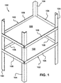
- FIG. 1 is an isometric view illustrating an example of a modular shelving system 100 incorporating the proposed concept. Many other examples can be devised based on this concept.
- the shelving system 100 includes two spaced-apart quadrilateral shelf assemblies 102, each being located at a given height from the floor surface.
- the shelf assemblies 102 are supported by four vertical corner posts 104.
- the shelving system 100 can include only one shelf assembly 102 or can include more than two shelf assemblies 102, depending on the implementation.
- Each shelf assembly 102 extends generally horizontally when the shelving system 100 is fully assembled, as shown in FIG. 1 .
- Each shelf assembly 102 of the illustrated example includes at least four elongated horizontal side rails 106 that are L-shaped in cross section.
- Each side rail 106 includes an inner side and an outer side. The inner side of the side rails 106 faces upwards when this shelving system 100 is fully assembled.
- FIG. 1 also shows the shelf assemblies 102 supporting a corresponding flat and substantially rigid board 108, for instance one made of plywood or the like, that rests on the inner side of the side rails 106.
- a corresponding flat and substantially rigid board 108 for instance one made of plywood or the like
- Other arrangements are also possible, for instance using a grate or other kinds of boards fitting tightly in-between the side rails 106.
- the boards 108 are optional parts of the shelf assemblies 102 that can be purchased or otherwise provided separately. Some implementations may not even need a board, for instance if one uses trays or the like.
- a shelf assembly 102 can also be used to support an equipment fitting over the side rails 106 without necessarily using a board or the like.
- FIG. 2 is an isometric view of one of the side rails 106 shown in FIG. 1 .
- the illustrated side rail 106 includes a body made of two substantially perpendicular and flat strips 110, 112 integrally connected to one another along a common junction 114, forming an L-shaped cross section.
- the side rail strip 110 will project substantially vertically and the side rail strip 112 will project substantially horizontally in the example of FIG. 1 once the parts of the shelving system 100 as assembled.
- the side rail 106 can be made of a one-piece material, for instance a laminated material.
- laminated materials include ones made of a plurality of laminated layers of fiberboard, paperboard and cardboard, to name just of few, forming a reinforced lightweight and substantially rigid product capable of supporting loads as required by most implementations. They are also relatively easy to machine and can be mass-produced at a relatively low cost. Nevertheless, other materials can be used as well. Using extruded plastic materials or even metallic materials for at least some of the parts is also possible.
- the side rail 106 further includes two open-ended first through slots 116, one for each of the opposite ends of the side rail 106.
- Each first through slot 116 extends lengthwise along the common junction 114 from a respective one of the side rail ends towards the other side rail end.
- the first through slots 116 have a periphery that is substantially rectilinear and substantially rectangular in cross section, and are all identical in the illustrated example. In the example of FIG. 1 , they are provided on the strip 112 that will extend substantially horizontally once the shelving system 100 is fully assembled. Variants are possible.
- FIG. 3 is an isometric view of one of the corner posts 104 shown in FIG. 1 .
- each corner post 104 in the example of FIG. 1 has an L-shaped body formed by two substantially perpendicular and flat strips 120 integrally connected to one another along a common junction 122.
- the corner post 104 extends rectilinearly between its two opposite ends. Variants are possible as well.
- the corner post 104 also includes an inner side and outer side.
- the corner post 104 can be made of a material identical or similar to the side rail 104, for instance a one-piece material that can be a laminated and substantially rigid material. One can also use different materials for the side rail 106 and the corner post 104.
- Each corner post strip 120 has a side edge 124 extending lengthwise. The side edges of the corner post strips 120 are rectilinear and parallel to one another in the illustrated example.
- Each corner post strip 120 also includes one or more open-ended second through slots 126 located at given distances between the corner post ends. There is at least one second through slot 126 in each corner post strip 120 for each shelf assembly 102 of the shelving system 100. However, one can provide more second through slots 126 than the number of actual shelf assemblies 102 for height adjustment purposes and/or for a wider height selection at the assembly time.
- Each second through slot 126 extends perpendicularly from the side edge 124 of the corresponding corner post strip 120 towards the common junction 122.
- FIG. 4 is an isometric view illustrating how the side rails 106 are connected to a corresponding one of the corner posts 104 to obtain the shelving system 100 of FIG. 1 .
- the side rails 106 are already positioned substantially horizontally while the corner post 104 is already positioned substantially vertically.
- the side rails 106 are oriented so that their inner side faces be upwards.
- the horizontally-projecting side rail strip 112 of the illustrated side rails 106 projects inwards from the common junction 114 with reference to the shelving system 100 being assembled, and the corresponding vertically-projecting strip 110 projects upwards from the common junction 114.
- Variants are also possible. Still, it should be noted that one can assemble the shelving system 100 differently, for instance with the corner posts 104 being horizontal, and put the shelving system 100 in an upright position when it is fully assembled.
- the first through slots 116 of the side rails 106 are configured and disposed for creating a detachable interdigitated and load-bearing engagement with a corresponding one of the second through slots 126 of the corner posts 126 when the side rail ends of connected to the corner posts 104 to support the corresponding shelf assembly 102 when the shelving system 100 is fully assembled.
- the weight of each side rail 106 and the weight of the items they will support are transmitted to corresponding ones of the corner posts 104.
- the length of the first through slots 116 and the length of the second through slots 126 are complimentary, thereby allowing the bottom of the first through slots 116 to engage the bottom of their corresponding second through slots 126 when the interdigitated engagement is made.
- the edge at the tip of the side rail 106 then abuts against the inner side of the corresponding corner post strip 120.
- the rest of the periphery of the first through slots 116 will be in direct contact with surfaces of the corresponding corner posts 104 and the rest of the periphery of the second through slots 126 will be in direct contact with surfaces of the corresponding horizontally-projecting side rail strip 112.
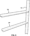
- FIG. 5 is an isometric view of the parts shown in FIG. 4 once connected together.
- each corner post strip 120 is insertable within the horizontally-projecting side rail strip 112 of the side rails 106 and the inner side of the corresponding vertically-projecting strips 110 is in direct contact with the outer side of the corner post strip 120.
- the width of the first through slots 116 corresponds approximately to the thickness of the corner post strip 120 and the width of the second through slots 126 corresponds approximately to the thickness of the horizontally-projecting side rail strip 112 of the side rails 106. This provides a tight fit between the peripheral surfaces of the through slots 116, 126 and the surfaces with which they co-engage. The friction holds the parts together, thereby giving the shelving system 100 strength and rigidity.
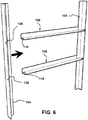
- FIG. 6 is an isometric view illustrating the connection of the parts shown in FIG. 5 with another one of the corner posts 104 being provided at the opposite ends of the side rails 106.
- FIG. 7 is an isometric view of the parts shown in FIG. 6 once connected together.
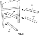
- FIG. 8 is an isometric view illustrating the connection of the parts shown in FIG. 7 with additional ones of the side rails 106.
- FIG. 9 is an enlarged isometric view illustrating the connection of one of the additional side rails 106 in FIG. 8 with one of the corner posts 104, as viewed from the inner side.
- the corner post 104 already has two side rails 106 on the other corner post strip 120.
- the second through slots 126 of each matching pair are positioned approximately at the same distance from the corner post ends but they are offset from one another. They are offset of a distance substantially corresponding to the thickness of the horizontally-projecting strip 120 of the side rails 106 to avoid obstruction. This provides clearance for the adjacent side rail 106 that is part of the same shelf assembly 102 when this adjacent side rail 106 is connected to the same corner post 104. As can be seen in FIG.
- the top edge of the horizontally-projecting side rail strip 112 of the side rail 106 on the left side is about at the same height than the bottom edge of the second through slot 126 with which the side rail 106 at the right is about to be connected to.
- the actual offset can also be slightly less than the thickness of the horizontally-projecting side rail strip 112 of the side rails 106 to create an interfering engagement between the top edge surface of the side rail 106 at the left and the bottom edge surface of the side rail 106 at the right. This increases friction and the forces holding the parts together.
- FIG. 10 is a view similar to FIG. 9 and illustrates the connection of another one of the additional side rails 106 in FIG. 8 with another one of the corner posts 104, as viewed from the inner side.
- one of the side rails 106 in FIG. 10 is the same side rail 106 as the one used in FIG. 9 .
- the corresponding side rail end is then at the top.
- the shelving system 100 so that both options are available.
- the bottom edge surfaces and the top edge surfaces of the side rails 106 can be machined to facilitate the fit and decrease the offset between the positions of the matching second through slots 126.
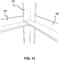
- FIG. 11 is an isometric view of the parts shown in FIG. 10 once the additional side rail 106 and the corner post 104 are connected together. As can be seen, the ends are overlapping. This overlapping creates a load-bearing engagement of one of the side rails 106 to the other.
- FIG. 12 is a view similar to FIG. 11 but from the outer side. As can be seen, the tip of the two adjacent vertically-projecting side rail strips 110 are spaced apart from one another since the tips of the corresponding horizontally-projecting side rail strips 112 abut on the inner side of the corner post 104. Alternatively, one can have the vertically-projecting side rail strips 110 longer than the horizontally-projecting side rail strips 112. Other variants are possible as well.
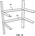
- FIG. 13 is an isometric view of the parts shown in FIG. 8 once connected together.
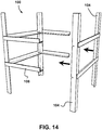
- FIG. 14 is an isometric view illustrating the connection of the parts shown in FIG. 13 with other side rails 106 and corner posts 104 to form the shelving system 100 of FIG. 1 .
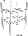
- FIG. 15 is an isometric view of the parts shown in FIG. 14 once connected together. These interlocked parts form a self-standing skeletal structure.
- FIG. 16 is an isometric view illustrating boards 108 being installed over a corresponding one of the shelf assemblies 102 on the shelving system of FIG. 15 .
- Each board 108 is cut for a tight fit between the inner sides of the corner posts 104 so as to form a tray.
- the side edges underneath the boards 108 rest by gravity on the inner top surface of the corresponding side rails 106.
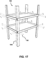
- FIG. 17 is an isometric view illustrating an example of how the side rails 106 and the corner posts 104 can be rigidly secured together.
- metallic staples 130 are used in this example.
- the vertically-projecting side rail strips 110 are secured to the corresponding corner post strips 120 using two staples 130.
- the staples 130 are installed after the installation of the boards 108. This way, an assembly worker can do fine adjustments before stapling the parts. Variants are possible as well.
- the side rails 106 and the corner posts 104 can be rigidly secured using other suitable mechanical fasteners or methods to add strength and rigidity. They can also be secured using staples 130 together with one or more other fasteners or methods, or be secured using a combination of other fasteners or methods. Examples of these other fasteners or methods include, depending on the material and to name just a few: nails, screws, bolts, dowels, glue, welding, brazing, riveting, outer strapping, push pins, etc.
- the shelving system 100 can be used alone, for instance with the bottom ends of the corner posts 104 resting directly on the floor surface, or be used for instance with a pallet positioned at the bottom thereof. When used with a pallet, the bottom ends of the corner posts 104 can rest directly on the floor surface or not.
- the pallet is useful for handling the shelving system 100 with a forklift or the like.
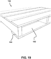
- FIG. 18 is an isometric view of the shelving system 100 of FIG. 1 being rigidly attached over an example of a pallet 140.
- This pallet 140 can be made for instance of wood.
- the pallet 140 is constructed with the bottom planks 142 being slightly outwardly offset from the rest of the pallet 140 to create a series of outwardly-projecting ledges 144 on which the bottom ends of the corner posts 104 can rest. In use, at least some of the weight from the shelving system 100 can be transmitted to the pallet 140 through the upper side of these ledges 144.
- the bottom section of the corner posts 104 are also stapled directly to the pallet 140 in the illustrated example, thereby rigidly securing the shelving system 100 and the pallet 140 together.
- the corner posts 104 and the pallet 140 can be rigidly secured together using other suitable fasteners or methods, for instance those already named above.
- the fasteners are staples 146 that are inserted directly through the bottom ends of the corner posts 104 and into the pallet 140. Variants are possible as well. For instance, one can use other kinds of fasteners.
- FIG. 19 is an enlarged isometric view of the pallet 140 shown in FIG. 18 .
- FIG. 20 is an isometric view of an example of implementation where two shelving systems 100 and their corresponding pallets 140 as shown in FIG. 18 are stacked, such as for storage, transportation and/or display.
- FIG. 21 is an enlarged view of the junction between the two shelving systems 100 shown in FIG. 20 .
- the upper pallet 140 includes four alignment corner blocks 148 (one being shown schematically in FIG. 21 ) on the underside, the corner blocks 148 being attached under the ledges 144.
- the corner blocks 148 are configured and disposed to fit on the top inner side of the corner posts 104, thereby facilitating the alignment and preventing the top shelving system 100 from moving sideways.
- the top ends of the corner posts 104 of the bottom shelving system 100 will engage the bottom surface of the ledges 144 of the pallet 140 to which the top shelving system 100 is attached. Positioning the shelving systems 100 over one another optimizes the storage floor space.
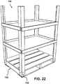
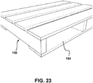
- FIG. 22 is a view similar to FIG. 18 but illustrates the shelving system 100 being rigidly attached over another example of a pallet, i.e. a standard pallet 150.
- This pallet 150 has no ledges.
- FIG. 23 is an enlarged isometric view of the pallet 150 shown in FIG. 22 .
- the corner posts 104 and the pallet 150 can be rigidly secured together using other suitable fasteners or methods.
- the fasteners are staples 152 that are inserted directly through the bottom ends of the corner posts 104 and into the pallet 150. Variants are possible as well. For instance, one can use other kinds of fasteners.
- FIG. 23 shown that the illustrated pallet 150 includes bottom planks 154.
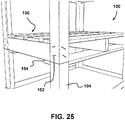
- FIG. 24 is a view similar to FIG. 20 , showing another example of an implementation where two shelving systems 100 as shown in FIG. 22 are stacked over one another.
- FIG. 25 is an enlarged view of the junction between the two shelving systems 100 shown in FIG. 24 .
- a vertical space was left between the bottom end of the corner posts 104 and the floor. This space corresponds approximately to the thickness of the bottom planks 154 of the pallet 150.
- the bottom ends of the corner posts 104 of the top shelving system 100 rest directly on the top end of the corresponding corner posts 104 of the bottom shelving system 100 and the bottom planks 154 of the pallet 150 to which the top shelving system 100 is attach prevent it from moving sideways.
- More than two shelving systems 100 can be stacked over one another, depending on the implementation.
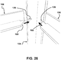
- FIG. 26 is an enlarged isometric view illustrating another example of a connection of side rails 106 with a corner post 104.
- FIG. 27 is an isometric view of the parts shown in FIG. 26 once connected together.
- the matching second through slots 126 of the corner post 104 are in registry with one another (i.e. are not vertically offset) and the inner edge of the horizontally-projecting side rail strips 112 at the ends of the side rails 106 are beveled.
- These beveled tips 160 have complementary angles.
- the illustrated example shows that they are each beveled at 45 degrees. Variants are possible as well.
- the top surface of the horizontally-projecting side rail strips 112 of the side rails 106 will form an uninterrupted leveled rim once this shelving system 100 will be fully assembled. This arrangement can be useful for smaller and lightweight implementations.
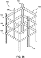
- FIG. 28 is an isometric view illustrating another example of a modular shelving system 100 incorporating the proposed concept. As can be seen, the shelving system 100 still includes four corner posts 104 but it also includes two intermediary vertical posts 170. Each shelf assembly 102 includes six side rails 106.
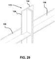
- FIG. 29 is an enlarged isometric view of the shelving system 100 of FIG. 28 .
- the junction between two adjacent side rails 106 and an intermediary post 170 is formed using two juxtaposed corner posts 104 that were rigidly attached together. They can be attached for instance using fasteners, such as staples, screws, etc., and/or glue. Other suitable fasteners and methods can also be used.
- two juxtaposed corner posts reduces the number of different parts. Nevertheless, one can use another kind of intermediary post, for instance a post pre-manufactured with a T-shaped cross section, thus which is not the combination of two corner posts 104.
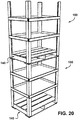
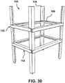
- FIG. 30 is an isometric view illustrating another example of a modular shelving system 100 incorporating the proposed concept.
- FIG. 31 is an enlarged isometric view of the inner side of one of the corner posts 104 of the shelving system 100 of FIG. 30 .
- This shelving system 100 is similar to the one shown in FIG. 1 but is configured upside-down. Thus, the inner side of the side rails 106 is facing downwards. This variant can be used for lightweight implementations.
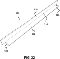
- FIG. 32 is an isometric view illustrating an example of a side rail 106 devoid of first through slot at both ends. This variant includes, at each end thereof, a cutaway portion 180 made in the horizontally-projecting side rail strip 112. The vertically-projecting side rail strip 110 of this side rail 106 is thus longer than the corresponding horizontally-projecting side rail strip 112.
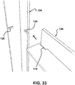
- FIG. 33 is an enlarged isometric view illustrating an example of a connection of one of the side rails 106 with a first through slot 116 to one of the corner posts 104.
- the first through slot 116 of the side rail 106 fits into the corresponding second through slot 126 of the corner post 104.This is similar to what is seen for instance in FIG. 4 .
- the side rail 106 will serve as a support for the side rail 106 shown in FIG. 32 .
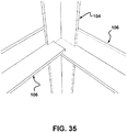
- FIG. 34 is an enlarged isometric view illustrating the connection of the side rail 106 of FIG. 32 with the corner post 104 of FIG. 33 .
- the edge portion of the horizontally-projecting side rail strip 112 that is at the corner of the vertically-projecting side rail strip 110 fits into the corresponding second through slot 126 of the corner post 104.
- This second through slot 126 is vertically offset with the matching second through slot 126 receiving the side rail 106 of about the thickness of the horizontally-projecting side rail strip 112.
- the bottom surface of the horizontally-projecting side rail strip 112 can rest directly over the top surface of the horizontally-projecting side rail strip 112 of the side rail 106. This overlapping creates a load-bearing engagement.
- FIG. 35 is an enlarged isometric view of the parts shown in FIG. 34 one connected together.
- each side rail 106 has one end with a first through slot 116 and an opposite end with a cutaway portion 180.
- the side rails 106 and the corner posts 104 can be rigidly secured using other suitable fasteners or methods.
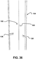
- One additional example is shown in FIGS. 36 to 40 .
- FIG. 36 is an isometric view illustrating an example of a corner post 104 with prefabricated holes 190 for receiving a fastener, such as screws, bolts, nails, dowels, rivets, etc.
- a fastener such as screws, bolts, nails, dowels, rivets, etc.
- These holes 190 can be made, for instance, by punching. Variants are possible as well.
- FIG. 37 is an enlarged isometric view illustrating the connection of a first one of the side rails 106 to the corner post 104 of FIG. 36 .
- the first side rail 106 includes holes 192 that are in registry with the holes 190 of the corner post 104 once the parts are in place.
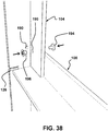
- FIG. 38 is an enlarged isometric view illustrating an example of a fastener being installed to secure the first side rail 106 to the corner post 104 of FIG. 37 .
- the fastener includes a screw 194 and a corresponding blind well nut 196. Variants are possible as well.
- FIG. 39 is an enlarged isometric view illustrating an example of a side rails 106 being connected to the corner post 104 of FIG. 38 .
- This second side rail 106 also includes holes 192.
- FIG. 40 is an enlarged isometric view illustrating an example of a fastener being installed to secure the second side rail 106 to the corner post 104 of FIG. 39 .
- the fastener also includes a screw 194 and a corresponding blind well nut 196. Variants are possible as well.
- a modular shelving system constructed as based on the proposed concept requires a very small number of parts and can be assembled very quickly.
- the configuration of the side rail ends 106 shown in FIG. 1 also increases the loading capacity of the shelving system 100.
- adding weight on one of the shelf assemblies 102 will increase the tendency of the corresponding side rails 106 of twisting inwards as the weight pushes downwards on the horizontally-projecting side rail strips 112.
- the position of the ends of the vertically-projecting side rail strips 110 will mitigate this buckling tendency since the corner post strips 120 are interlocked with the side rail ends.
- the shelving systems incorporating the proposed concept can be used in a wide range of applications and purposes, including for instance fresh cut flowers or plants in their pots. They can be used in transportation, storage and/or display at the point-of-sale, for instance in a store where customers may take the items directly from the shelves. They can be unassembled after use and send back to the point of origin in a compact shipment of piled parts to be used again later. They are attractive, have a clean look, are lightweight, provide an optimum finger space and can be easily and quickly assembled without the need of any special tools or experience, even by a single person. One can even use shelving systems as displays for marketing purposes, for instance in store aisleways, trade-shows, etc., or even as low-cost furniture in residences and/or institutions. Many other uses are possible a well.
- a shelving system incorporating the proposed concept can be made using side rails that are all identical to one another and using corner posts that are all identical to one another.
- only one model of side rail and only one model of corner post are used for forming a shelving system for ease of manufacture, inventory and assembly.
- Other variants are possible as well.
- the corners posts and/or the side rails can be asymmetric, i.e. having one slat larger than the other one.
- Many different configurations of shelving systems are possible, depending on the needs.
- the ones using quadrilateral shelf assemblies will be suitable for most users, it is possible to have shelving systems where only three corner posts are provided.
- the strips of these corners posts can be at 120 degrees from one another instead of being at right angle.
Landscapes
- Engineering & Computer Science (AREA)
- Mechanical Engineering (AREA)
- Assembled Shelves (AREA)
Claims (15)
- Modulares Regalsystem (100), beinhaltend:eine Regalbaugruppe (102), wobei die Regalbaugruppe (102) eine Vielzahl von länglichen, sich horizontal erstreckenden Seitenschienen (106) beinhaltet, wobei jede Seitenschiene (106) zwei gegenüberliegende Enden und einen Körper aufweist, der durch zwei im Wesentlichen senkrechte und flache Streifen (110, 112) gebildet ist, die entlang einer gemeinsamen Verbindungsstelle (114) einstückig miteinander verbunden sind,wobei einer der Seitenschienenstreifen (110, 112) ein vertikal vorstehender Seitenschienenstreifen (110) ist und der andere ein horizontal vorstehender Seitenschienenstreifen (112) ist,wobei jede Seitenschiene (106) ferner eine Innenseite und eine Außenseite beinhaltet, wobei zumindest einige der Seitenschienen (106) zumindest einen ersten Durchgangsschlitz mit offenem Ende (116) beinhalten, wobei sich jeder erste Durchgangsschlitz (116) von einem entsprechenden der Seitenschienenenden entlang der gemeinsamen Verbindungsstelle (114) längs auf dem horizontal vorstehenden Seitenschienenstreifen (112) erstreckt; undeine Vielzahl von länglichen, sich vertikal erstreckenden Eckpfosten (104), mit denen die Seitenschienenenden verbunden sind, um eine selbststehende Gerüststruktur zu bilden, wobei jeder Eckpfosten (104) zwei gegenüberliegende Enden, eine Innenseite, eine Außenseite und einen Körper aufweist, der durch zwei im Wesentlichen flache Streifen (120) gebildet wird, die entlang einer gemeinsamen Verbindungsstelle (122) einstückig miteinander verbunden sind, wobei jeder Eckpfostenstreifen (120) eine Seitenkante (124) aufweist, die sich längs erstreckt und zumindest einen zweiten Durchgangsschlitz mit offenem Ende (126), der sich in einem gegebenen Abstand zwischen den Eckpfostenenden befindet und der sich senkrecht von der Seitenkante (124) in Richtung der gemeinsamen Verbindungsstelle (122) des Eckpfostens (104) erstreckt, wobei jeder erste Durchgangsschlitz (116) eine lösbare ineinander greifende und lasttragende Eingriffnahme mit einem entsprechenden von den zweiten Durchgangsschlitzen (126) bildet, um die Regalbaugruppe (102) zu stützen.
- Regalsystem (100) nach Anspruch 1, wobei die Regalbaugruppe (102) vierseitig ist und Seitenschienen (106) beinhaltet, deren Anzahl zumindest vier ist, wobei das Regalsystem (100) Eckpfosten (104) beinhaltet, deren Anzahl vier ist, wobei die Eckpfostenstreifen (120) jedes Eckpfostens (104) vorzugsweise im rechten Winkel zueinander positioniert sind.
- Regalsystem (100) nach Anspruch 1 oder 2, wobei es mehr als eine Regalbaugruppe (102) gibt und jeder Eckpfostenstreifen (120) mehr als einen zweiten Durchgangsschlitz (126) beinhaltet, wobei die zweiten Durchgangsschlitze (126) an jedem Eckpfostenstreifen (120) seitlich auf einen entsprechenden gegenüberliegenden der zweiten Durchgangsschlitze (126) ausgerichtet sind, um ein Paar zu bilden, wobei die Paare an zweiten Durchgangsschlitzen (126) voneinander beabstandet sind und ihre Anzahl zumindest gleich der Anzahl an Regalbaugruppen (102) ist.
- Regalsystem (100) nach einem der Ansprüche 1 bis 3, wobei zumindest einige der Seitenschienen (106) eine abgeschrägte Spitze an dem horizontal vorstehenden Seitenschienenstreifen (112) beinhalten.
- Regalsystem (100) nach Anspruch 3, wobei die zweiten Durchgangsschlitze (126) jedes Paares in einem Abstand, der im Wesentlichen einer Dicke des horizontal vorstehenden Seitenschienenstreifens (112) entspricht, vertikal zueinander versetzt sind, wobei zumindest einige der Seitenschienen (106) vorzugsweise einen ausgeschnittenen Abschnitt an dem horizontal vorstehenden Seitenschienenstreifen (112) beinhalten.
- Regalsystem (100) nach Anspruch 5, wobei die horizontal vorstehenden Seitenschienenstreifen (112) von zwei benachbarten der Seitenschienen (106) an der Innenseite des entsprechenden Eckpfostens (104) überlappen.
- Regalsystem (100) nach einem der Ansprüche 1 bis 5, wobei:jedes Ende der Seitenschienen (106) einen entsprechenden der ersten Durchgangsschlitze (116) beinhaltet; und/oder wobei die Eingriffnahme zwischen den ersten Durchgangsschlitzen (116) und den zweiten Durchgangsschlitzen (126) eine Presspassung beinhaltet.
- Regalsystem (100) nach einem der Ansprüche 1 bis 7, wobei:die Eckpfosten (104) und die Seitenschienen (106) auch mit Befestigungen fest aneinander befestigt sind, wobei die Befestigungen vorzugsweise zumindest eine Klammer (130) beinhalten, die durch jedes Seitenschienenende und den entsprechenden Eckpfosten (104) bereitgestellt ist; und/oderdie Eckpfosten (104) vorgefertigte Löcher (190) beinhalten und die Seitenschienen (106) vorgefertigte Löcher (190) beinhalten, wobei die Eckpfostenlöcher (190) deckungsgleich zu entsprechenden der Seitenschienenlöcher (192) sind, sobald das Regalsystem (100) aufgebaut ist, um Befestigungen aufzunehmen.
- Regalsystem (100) nach einem der Ansprüche 1 bis 8, wobei untere Enden der Eckpfosten (104) fest an entsprechenden Seiten einer Palette (140, 150) befestigt sind.
- Regalsystem (100) nach Anspruch 9, wobei:die unteren Enden der Eckpfosten (104) von einem Boden beabstandet sind, auf dem die Palette (140, 150) aufliegt; und/oderdie unteren Enden der Eckpfosten (104) eine obere Seite von entsprechenden Leisten (144) in Eingriff nehmen, die sich von einer unteren Seite der Palette (140) nach außen erstrecken, wobei die Palette (140) vorzugsweise ferner vier beabstandete Ausrichtungseckblöcke (148) beinhaltet, die unter den Leisten (144) der Palette (140) angebracht sind.
- Regalsystem (100) nach einem der Ansprüche 1 bis 10, wobei das Regalsystem (100) zumindest einen vertikalen Zwischenpfosten (170) beinhaltet, mit dem einige der Seitenschienen (106) verbunden sind.
- Regalsystem (100) nach Anspruch 11, wobei der vertikale Zwischenpfosten (170) aus zwei zusätzlichen Eckpfosten (104) gefertigt ist, die nebeneinandergestellt sind, wobei der vertikale Zwischenpfosten (170) vorzugsweise einen T-förmigen Querschnitt aufweist.
- Regalsystem (100) nach Anspruch 1 oder 2, wobei die Regalbaugruppe (102) ferner eine Platte (108) beinhaltet, die von den horizontal vorstehenden Seitenschienenstreifen (112) gestützt wird.
- Regalsystem (100) nach einem der Ansprüche 1 bis 13, wobei:jeder der Eckpfosten (104) aus einem einstückigen Material gefertigt ist; und/oderjede der Seitenschienen (106) aus einem einstückigen Material gefertigt ist, wobei das einstückige Material vorzugsweise ein Material ist, das aus laminierten Schichten aus Faserplatte, Pappe und/oder Karton gefertigt ist.
- Regalsystem (100) nach einem der Ansprüche 1 bis 14, wobei die Seitenschienen (106) miteinander identisch sind und die Eckpfosten (104) miteinander identisch sind, wobei die ersten Durchgangsschlitze (116) und die zweiten Durchgangsschlitze (126) vorzugsweise jeweils einen Umfang aufweisen, der im Wesentlichen geradlinig ist und dessen Querschnitt im Wesentlichen rechteckig ist.
Priority Applications (1)
| Application Number | Priority Date | Filing Date | Title |
|---|---|---|---|
| PL14782967T PL2983552T3 (pl) | 2013-04-08 | 2014-04-07 | Modułowy system regałowy |
Applications Claiming Priority (2)
| Application Number | Priority Date | Filing Date | Title |
|---|---|---|---|
| US201361809662P | 2013-04-08 | 2013-04-08 | |
| PCT/CA2014/050353 WO2014165988A1 (en) | 2013-04-08 | 2014-04-07 | Modular shelving system |
Publications (3)
| Publication Number | Publication Date |
|---|---|
| EP2983552A1 EP2983552A1 (de) | 2016-02-17 |
| EP2983552A4 EP2983552A4 (de) | 2016-12-14 |
| EP2983552B1 true EP2983552B1 (de) | 2018-01-03 |
Family
ID=51688790
Family Applications (1)
| Application Number | Title | Priority Date | Filing Date |
|---|---|---|---|
| EP14782967.5A Not-in-force EP2983552B1 (de) | 2013-04-08 | 2014-04-07 | Modulares regalsystem |
Country Status (8)
| Country | Link |
|---|---|
| US (1) | US9204737B2 (de) |
| EP (1) | EP2983552B1 (de) |
| CN (1) | CN105246375B (de) |
| CA (1) | CA2861626C (de) |
| ES (1) | ES2664765T3 (de) |
| MX (1) | MX358419B (de) |
| PL (1) | PL2983552T3 (de) |
| WO (1) | WO2014165988A1 (de) |
Families Citing this family (13)
| Publication number | Priority date | Publication date | Assignee | Title |
|---|---|---|---|---|
| PL2983552T3 (pl) | 2013-04-08 | 2018-06-29 | Présentoirs One Way Inc. | Modułowy system regałowy |
| US10709238B1 (en) * | 2015-07-24 | 2020-07-14 | Richard Simon Thompson | Shelf system improvements |
| WO2017147665A1 (pt) * | 2016-03-04 | 2017-09-08 | Chung Kwo Tzuo | Suporte para perfil e parede lateral de display expositor, com sistema de montagem |
| US10143298B2 (en) | 2016-04-07 | 2018-12-04 | Douglas Wood | Modular structural support apparatus and method of constructing the same |
| US10182652B1 (en) * | 2017-12-21 | 2019-01-22 | Google Llc | Interactive kiosk shelves |
| US10752276B1 (en) * | 2018-09-26 | 2020-08-25 | Itool Equipment Holding Llc | Framed structure for material-handling purposes |
| US10835058B2 (en) * | 2019-01-15 | 2020-11-17 | Josh Sale | Paper composite nursery shipping rack |
| GB2585632B8 (en) * | 2019-05-13 | 2023-06-28 | The West Retail Group Ltd | Kit of parts for a kitchen unit |
| USD942784S1 (en) * | 2019-10-08 | 2022-02-08 | Brian Burge | Table |
| CN110840123B (zh) * | 2019-10-24 | 2025-09-09 | 宁波欧琳整体厨房有限公司 | 一种搁架及衣帽间 |
| US11350770B2 (en) * | 2019-11-07 | 2022-06-07 | Signode Industrial Group Llc | Storage, shipping, and display unit |
| US20210186211A1 (en) * | 2019-12-20 | 2021-06-24 | Cambro Manufacturing Company | Shelving System for Resisting Applied Shear Forces and Method for Forming the Same |
| FR3149174B1 (fr) * | 2023-05-30 | 2025-05-02 | Nestor Location | Ensemble de stockage modulable |
Family Cites Families (77)
| Publication number | Priority date | Publication date | Assignee | Title |
|---|---|---|---|---|
| US11449A (en) * | 1854-08-01 | Simon willard | ||
| GB144765A (en) | 1919-03-12 | 1920-06-14 | Harold Weston Wells | Improvements in or relating to sectional toys |
| US2068771A (en) | 1934-10-30 | 1937-01-26 | Ashtabula Corrugated Box Compa | Corner protector |
| GB890764A (en) | 1960-02-22 | 1962-03-07 | Marler Haley Studios Ltd | Improvements in display stands having detachable and interfitting parts |
| US3081139A (en) * | 1960-08-02 | 1963-03-12 | Gen Motors Corp | Adjustable electronic chassis mounting |
| US3294250A (en) * | 1964-03-05 | 1966-12-27 | Aurora Equipment Co | Shelving structure |
| US3337111A (en) | 1964-10-14 | 1967-08-22 | Continental Can Co | Corner post |
| US3339750A (en) * | 1965-08-09 | 1967-09-05 | Hana Corp | Structural connector |
| US3433354A (en) | 1968-01-29 | 1969-03-18 | Paper Extrusions Co | Resilient angle member |
| US3536245A (en) | 1968-06-17 | 1970-10-27 | Jones & Laughlin Steel Corp | Corner post with corrugated steel insert |
| US3559339A (en) * | 1968-11-04 | 1971-02-02 | Robert W Worley | Collapsible plant stake assembly |
| US3647080A (en) | 1970-06-12 | 1972-03-07 | Inca Metal Products Corp | Structural element and structure |
| US3846944A (en) * | 1970-12-21 | 1974-11-12 | Barton King Syst Corp | Structural self-supporting system |
| US3734389A (en) | 1971-04-15 | 1973-05-22 | Inland Container Corp | Package corner post |
| US3862691A (en) * | 1973-06-01 | 1975-01-28 | Lear Siegler Inc | Lock span shelving |
| US3948581A (en) | 1974-07-02 | 1976-04-06 | Helman Philip L | Knockdown furniture assemblies |
| US4034683A (en) * | 1975-07-28 | 1977-07-12 | Dicenzo Guy J | Shelving structure |
| US4039132A (en) | 1976-01-05 | 1977-08-02 | Fournier Peter R | Plant support structure |
| US4235493A (en) | 1978-12-11 | 1980-11-25 | Chromalloy American Corporation | Knockdown cabinet assembly |
| US4270661A (en) * | 1979-05-03 | 1981-06-02 | Parsteel Products & Services Company, Inc. | Battery storage rack |
| US4342397A (en) * | 1980-09-08 | 1982-08-03 | Halstrick Robert T | Fastenings for storage racks |
| US4549665A (en) | 1982-09-03 | 1985-10-29 | Republic Steel Corporation | Shelf assembly |
| FR2542594B1 (fr) | 1983-03-15 | 1988-05-27 | Spindel Yves | Presentation nouvelle des fleurs et des arbustes |
| GB2140670B (en) * | 1983-06-03 | 1987-04-08 | Hsiao Yu Sheng | Safety steel angle assembly rack |
| US4949648A (en) * | 1984-07-16 | 1990-08-21 | Samsung Electronics Co., Ltd. | Sheet metal shelving assembly |
| FR2582286B1 (fr) | 1985-05-24 | 1988-04-15 | Lebalch Herve | Conteneur de transport avec plateaux intercalaires |
| US4852501A (en) | 1986-05-16 | 1989-08-01 | Amco Corporation | Adjustable rack of shelves |
| US4712695A (en) * | 1986-07-25 | 1987-12-15 | Cheng Huey Der | Structural frame connector |
| US4771893A (en) | 1987-05-13 | 1988-09-20 | Shippers Paper Products Company | Corrugated paper corner post |
| DE8807115U1 (de) * | 1988-05-27 | 1988-12-01 | Kufus, Axel, 1000 Berlin | Regalbausatz |
| US5096648A (en) | 1988-08-03 | 1992-03-17 | Johnson Brothers Precision Precast Products, Inc. | Method of manufacturing precast concrete articles |
| US4973110A (en) | 1988-09-12 | 1990-11-27 | Nyquist Lawrence M | Structural frame assembly |
| GB8824397D0 (en) | 1988-10-18 | 1988-11-23 | Kirpal Singh Sihra | Building system |
| US4865201A (en) | 1988-12-19 | 1989-09-12 | Shippers Paper Products Company | Combination laminated corrugated paper corner post |
| US4856434A (en) | 1988-12-27 | 1989-08-15 | Smith Gene A | Smitty table |
| GB2232426B (en) | 1989-06-08 | 1993-11-17 | Square D Co | Framework assembly system |
| US5048689A (en) | 1990-10-15 | 1991-09-17 | International Paper Company | Corrugated paperboard corner post |
| US5185982A (en) * | 1991-09-23 | 1993-02-16 | Stark Forest Products Inc. | Corner joint for modular assemblies |
| US5181611A (en) | 1991-12-16 | 1993-01-26 | Liebel Henry L | Corner post having laminated paperboard spine |
| US5553549A (en) * | 1992-04-01 | 1996-09-10 | Spacemaker Limited | Framework for shelving unit |
| US5267651A (en) | 1992-04-15 | 1993-12-07 | Hughes Billy R | Support post for packaging system |
| FR2690898B1 (fr) | 1992-05-05 | 1996-02-16 | Rlg Concepts | Nouveau conteneur constitue d'elements assembles recuperables. |
| US5351846A (en) | 1992-05-29 | 1994-10-04 | Carter Associates, Inc. | Sidewall structure for stackable bin |
| US5452812A (en) | 1993-07-13 | 1995-09-26 | Sycamore Systems, Inc. | Shelving system |
| US5632390A (en) | 1995-12-22 | 1997-05-27 | Podergois; Jeffrey A. | Foldable display assembly |
| US5813737A (en) * | 1997-02-13 | 1998-09-29 | Stone; Adrian Thomas | Construction system |
| US20060032412A1 (en) | 1997-05-23 | 2006-02-16 | Ez Shipper Racks, Inc. | Caster assembly suited for use with modular racks |
| US5979338A (en) | 1997-05-23 | 1999-11-09 | Salmanson; Jeffrey | Modular low cost pallet and shelf assembly |
| GB2334202A (en) | 1998-02-14 | 1999-08-18 | Timothy Derek Davis | Display unit of folded sheet material |
| US6378710B1 (en) | 1999-06-14 | 2002-04-30 | Menasha Corporation | Adjustable shelf unit |
| US6540080B2 (en) | 1999-08-10 | 2003-04-01 | Albert Moreyra | Protective wrap for protecting and packaging and method for producing same |
| TW475380U (en) * | 2000-07-17 | 2002-02-01 | Jin-Shr Lin | Improved assembly structure of screwless angle steel frame |
| US20020195029A1 (en) | 2001-06-22 | 2002-12-26 | Dale Walton | Adjustable sliding-shelf assemblies and method of adjusting the same |
| US6814529B2 (en) | 2002-04-08 | 2004-11-09 | Friedola Gebr, Holzapef Gmbh & Co. Kg | Transport container for unit goods |
| US6962262B2 (en) | 2003-02-10 | 2005-11-08 | Dennis Toma | Connecting corner for knock down racks |
| US7252202B2 (en) * | 2003-11-17 | 2007-08-07 | Edsal Manufacturing Co., Inc. | Cargo rack |
| US6976732B2 (en) | 2004-05-03 | 2005-12-20 | Thomas David L | Convertible furniture system comprised of modular convertible box frames and methods of forming various furniture configurations therefrom |
| US20060124568A1 (en) | 2004-12-14 | 2006-06-15 | De Alba Luis F R | Self-standing exhibiting package |
| US20060144809A1 (en) * | 2004-12-30 | 2006-07-06 | Edsal Manufacturing Co., Inc. | Shelving connector |
| US9439508B2 (en) * | 2005-01-27 | 2016-09-13 | Edsal Manufacturing Company, Inc. | Outside wrap post coupler with assembly assist |
| GB0508216D0 (en) * | 2005-04-23 | 2005-06-01 | Reality Products Ltd | Structural joint |
| JP2007000409A (ja) * | 2005-06-24 | 2007-01-11 | Yoshihiro Hasegawa | 組み立て棚 |
| MXPA05011459A (es) | 2005-10-25 | 2007-04-24 | Alba Luis Felipe Rego Garcia D | Estructura de empaque para la contencion, transportacion, exhibicion y expendio de productos. |
| CN200962983Y (zh) * | 2006-09-28 | 2007-10-24 | 刘舜程 | 木质家俱组合件结合构造 |
| DE202007001060U1 (de) * | 2006-11-29 | 2007-04-26 | Ehl, Joseph | Modulares Wandregal |
| US20100187226A1 (en) | 2007-02-26 | 2010-07-29 | Power Retailing Group S.A. De C.V. | Easy-to-dismantle display packaging |
| KR100919671B1 (ko) * | 2007-09-10 | 2009-10-06 | 최천순 | 무볼팅 조립식 선반장치 |
| US8079315B2 (en) | 2007-09-12 | 2011-12-20 | Roger Jason Berent | Flat pack friction fit furniture system |
| MX2008010916A (es) | 2008-08-26 | 2010-04-13 | Power Retailing Group S A De C | Tarima para contener y transportar objetos. |
| WO2011045624A1 (es) | 2009-10-12 | 2011-04-21 | Bernardo Herman Baran | Extructura para exhibir productos con multiples soportes y metodo de ensamble del mismo |
| CN102038373A (zh) * | 2009-10-24 | 2011-05-04 | 李增清 | 柜体结构 |
| CN201536797U (zh) * | 2009-11-04 | 2010-08-04 | 金福楠 | 一种组合式支撑架 |
| WO2011070383A1 (es) | 2009-12-09 | 2011-06-16 | Bernardo Herman Baran | Estructura para exhibir productos y método de ensamble y desensamble del mismo |
| MX2010002817A (es) | 2010-03-12 | 2011-09-15 | Power Retailing Group S A De C V | Estructura reforzada para embalaje, transporte y exhibicion de productos varios. |
| WO2012053971A1 (en) * | 2010-10-19 | 2012-04-26 | Innoplan Technology Pte Ltd | An assembly for distributing loading forces onto a panel structure and a method for putting together the aforementioned assembly (u beam) |
| GB2492137A (en) | 2011-06-23 | 2012-12-26 | Printed Image Ltd | Fold-up display |
| PL2983552T3 (pl) | 2013-04-08 | 2018-06-29 | Présentoirs One Way Inc. | Modułowy system regałowy |
-
2014
- 2014-04-07 PL PL14782967T patent/PL2983552T3/pl unknown
- 2014-04-07 ES ES14782967.5T patent/ES2664765T3/es active Active
- 2014-04-07 WO PCT/CA2014/050353 patent/WO2014165988A1/en not_active Ceased
- 2014-04-07 CA CA2861626A patent/CA2861626C/en active Active
- 2014-04-07 CN CN201480030055.5A patent/CN105246375B/zh not_active Expired - Fee Related
- 2014-04-07 EP EP14782967.5A patent/EP2983552B1/de not_active Not-in-force
- 2014-04-07 MX MX2015014160A patent/MX358419B/es active IP Right Grant
-
2015
- 2015-02-17 US US14/624,345 patent/US9204737B2/en active Active
Non-Patent Citations (1)
| Title |
|---|
| None * |
Also Published As
| Publication number | Publication date |
|---|---|
| EP2983552A1 (de) | 2016-02-17 |
| WO2014165988A1 (en) | 2014-10-16 |
| MX358419B (es) | 2018-08-17 |
| CN105246375A (zh) | 2016-01-13 |
| CN105246375B (zh) | 2017-10-20 |
| CA2861626C (en) | 2015-02-24 |
| PL2983552T3 (pl) | 2018-06-29 |
| ES2664765T3 (es) | 2018-04-23 |
| MX2015014160A (es) | 2017-06-20 |
| US9204737B2 (en) | 2015-12-08 |
| CA2861626A1 (en) | 2014-10-16 |
| US20150157144A1 (en) | 2015-06-11 |
| EP2983552A4 (de) | 2016-12-14 |
Similar Documents
| Publication | Publication Date | Title |
|---|---|---|
| EP2983552B1 (de) | Modulares regalsystem | |
| US8091715B2 (en) | Adjustable pallet display unit | |
| US7516708B2 (en) | Interlocking table with integral magazine holder | |
| US7704170B2 (en) | Four piece table tennis table having a stabilized joint | |
| KR101478953B1 (ko) | 조립식 선반 | |
| US4418627A (en) | Shelf-type storage system | |
| US4171058A (en) | Knock-down slot-lock container | |
| US6585028B2 (en) | Modular wall system | |
| US20050109723A1 (en) | Shelf assembly display jacket | |
| US10362860B2 (en) | Flat pack end table and coffee table | |
| CN105121308A (zh) | 集装箱储存系统以及该集装箱储存系统的支撑件和横梁 | |
| US9370264B2 (en) | Display shelving formed of corrugated fiberboard | |
| US9173489B2 (en) | Storage rack divider kit and apparatus | |
| KR100694203B1 (ko) | 선반 기능을 가진 조립식 파레트 겸용 박스 | |
| US20150298850A1 (en) | Portable display containers and methods of making and using the same | |
| GB2534881A (en) | Stacking modular box shelving system | |
| US10433640B2 (en) | Modular furniture | |
| EP3515831B1 (de) | Trägerelement für plattenförmige gegenstände | |
| EP2363040B1 (de) | Regale | |
| KR20170011017A (ko) | 앵글 무볼트 파일 선반 | |
| JP3224503U (ja) | 木製シェルフ | |
| EP2799358B1 (de) | Montierbarer behälter | |
| EP3552518B1 (de) | Regal | |
| WO2017003377A1 (en) | A container assembly | |
| JP7064745B2 (ja) | ステージボックス |
Legal Events
| Date | Code | Title | Description |
|---|---|---|---|
| PUAI | Public reference made under article 153(3) epc to a published international application that has entered the european phase |
Free format text: ORIGINAL CODE: 0009012 |
|
| 17P | Request for examination filed |
Effective date: 20151103 |
|
| AK | Designated contracting states |
Kind code of ref document: A1 Designated state(s): AL AT BE BG CH CY CZ DE DK EE ES FI FR GB GR HR HU IE IS IT LI LT LU LV MC MK MT NL NO PL PT RO RS SE SI SK SM TR |
|
| AX | Request for extension of the european patent |
Extension state: BA ME |
|
| DAX | Request for extension of the european patent (deleted) | ||
| A4 | Supplementary search report drawn up and despatched |
Effective date: 20161116 |
|
| RIC1 | Information provided on ipc code assigned before grant |
Ipc: A47F 5/11 20060101ALI20161110BHEP Ipc: A47B 47/00 20060101ALI20161110BHEP Ipc: A47B 57/34 20060101ALI20161110BHEP Ipc: A47F 5/00 20060101ALI20161110BHEP Ipc: A47F 5/10 20060101ALI20161110BHEP Ipc: A47B 47/05 20060101AFI20161110BHEP Ipc: B65D 19/44 20060101ALI20161110BHEP Ipc: A47B 47/06 20060101ALI20161110BHEP |
|
| GRAP | Despatch of communication of intention to grant a patent |
Free format text: ORIGINAL CODE: EPIDOSNIGR1 |
|
| INTG | Intention to grant announced |
Effective date: 20170906 |
|
| GRAS | Grant fee paid |
Free format text: ORIGINAL CODE: EPIDOSNIGR3 |
|
| GRAA | (expected) grant |
Free format text: ORIGINAL CODE: 0009210 |
|
| AK | Designated contracting states |
Kind code of ref document: B1 Designated state(s): AL AT BE BG CH CY CZ DE DK EE ES FI FR GB GR HR HU IE IS IT LI LT LU LV MC MK MT NL NO PL PT RO RS SE SI SK SM TR |
|
| REG | Reference to a national code |
Ref country code: GB Ref legal event code: FG4D |
|
| REG | Reference to a national code |
Ref country code: CH Ref legal event code: EP Ref country code: AT Ref legal event code: REF Ref document number: 959457 Country of ref document: AT Kind code of ref document: T Effective date: 20180115 |
|
| REG | Reference to a national code |
Ref country code: IE Ref legal event code: FG4D |
|
| REG | Reference to a national code |
Ref country code: DE Ref legal event code: R096 Ref document number: 602014019468 Country of ref document: DE |
|
| REG | Reference to a national code |
Ref country code: ES Ref legal event code: FG2A Ref document number: 2664765 Country of ref document: ES Kind code of ref document: T3 Effective date: 20180423 |
|
| REG | Reference to a national code |
Ref country code: FR Ref legal event code: PLFP Year of fee payment: 5 |
|
| REG | Reference to a national code |
Ref country code: NL Ref legal event code: MP Effective date: 20180103 |
|
| REG | Reference to a national code |
Ref country code: LT Ref legal event code: MG4D |
|
| REG | Reference to a national code |
Ref country code: AT Ref legal event code: MK05 Ref document number: 959457 Country of ref document: AT Kind code of ref document: T Effective date: 20180103 |
|
| PG25 | Lapsed in a contracting state [announced via postgrant information from national office to epo] |
Ref country code: NL Free format text: LAPSE BECAUSE OF FAILURE TO SUBMIT A TRANSLATION OF THE DESCRIPTION OR TO PAY THE FEE WITHIN THE PRESCRIBED TIME-LIMIT Effective date: 20180103 |
|
| PG25 | Lapsed in a contracting state [announced via postgrant information from national office to epo] |
Ref country code: HR Free format text: LAPSE BECAUSE OF FAILURE TO SUBMIT A TRANSLATION OF THE DESCRIPTION OR TO PAY THE FEE WITHIN THE PRESCRIBED TIME-LIMIT Effective date: 20180103 Ref country code: LT Free format text: LAPSE BECAUSE OF FAILURE TO SUBMIT A TRANSLATION OF THE DESCRIPTION OR TO PAY THE FEE WITHIN THE PRESCRIBED TIME-LIMIT Effective date: 20180103 Ref country code: NO Free format text: LAPSE BECAUSE OF FAILURE TO SUBMIT A TRANSLATION OF THE DESCRIPTION OR TO PAY THE FEE WITHIN THE PRESCRIBED TIME-LIMIT Effective date: 20180403 Ref country code: FI Free format text: LAPSE BECAUSE OF FAILURE TO SUBMIT A TRANSLATION OF THE DESCRIPTION OR TO PAY THE FEE WITHIN THE PRESCRIBED TIME-LIMIT Effective date: 20180103 Ref country code: CY Free format text: LAPSE BECAUSE OF FAILURE TO SUBMIT A TRANSLATION OF THE DESCRIPTION OR TO PAY THE FEE WITHIN THE PRESCRIBED TIME-LIMIT Effective date: 20180103 |
|
| PG25 | Lapsed in a contracting state [announced via postgrant information from national office to epo] |
Ref country code: LV Free format text: LAPSE BECAUSE OF FAILURE TO SUBMIT A TRANSLATION OF THE DESCRIPTION OR TO PAY THE FEE WITHIN THE PRESCRIBED TIME-LIMIT Effective date: 20180103 Ref country code: AT Free format text: LAPSE BECAUSE OF FAILURE TO SUBMIT A TRANSLATION OF THE DESCRIPTION OR TO PAY THE FEE WITHIN THE PRESCRIBED TIME-LIMIT Effective date: 20180103 Ref country code: RS Free format text: LAPSE BECAUSE OF FAILURE TO SUBMIT A TRANSLATION OF THE DESCRIPTION OR TO PAY THE FEE WITHIN THE PRESCRIBED TIME-LIMIT Effective date: 20180103 Ref country code: GR Free format text: LAPSE BECAUSE OF FAILURE TO SUBMIT A TRANSLATION OF THE DESCRIPTION OR TO PAY THE FEE WITHIN THE PRESCRIBED TIME-LIMIT Effective date: 20180404 Ref country code: IS Free format text: LAPSE BECAUSE OF FAILURE TO SUBMIT A TRANSLATION OF THE DESCRIPTION OR TO PAY THE FEE WITHIN THE PRESCRIBED TIME-LIMIT Effective date: 20180503 Ref country code: SE Free format text: LAPSE BECAUSE OF FAILURE TO SUBMIT A TRANSLATION OF THE DESCRIPTION OR TO PAY THE FEE WITHIN THE PRESCRIBED TIME-LIMIT Effective date: 20180103 Ref country code: BG Free format text: LAPSE BECAUSE OF FAILURE TO SUBMIT A TRANSLATION OF THE DESCRIPTION OR TO PAY THE FEE WITHIN THE PRESCRIBED TIME-LIMIT Effective date: 20180403 |
|
| REG | Reference to a national code |
Ref country code: DE Ref legal event code: R097 Ref document number: 602014019468 Country of ref document: DE |
|
| PG25 | Lapsed in a contracting state [announced via postgrant information from national office to epo] |
Ref country code: AL Free format text: LAPSE BECAUSE OF FAILURE TO SUBMIT A TRANSLATION OF THE DESCRIPTION OR TO PAY THE FEE WITHIN THE PRESCRIBED TIME-LIMIT Effective date: 20180103 Ref country code: IT Free format text: LAPSE BECAUSE OF FAILURE TO SUBMIT A TRANSLATION OF THE DESCRIPTION OR TO PAY THE FEE WITHIN THE PRESCRIBED TIME-LIMIT Effective date: 20180103 Ref country code: EE Free format text: LAPSE BECAUSE OF FAILURE TO SUBMIT A TRANSLATION OF THE DESCRIPTION OR TO PAY THE FEE WITHIN THE PRESCRIBED TIME-LIMIT Effective date: 20180103 Ref country code: RO Free format text: LAPSE BECAUSE OF FAILURE TO SUBMIT A TRANSLATION OF THE DESCRIPTION OR TO PAY THE FEE WITHIN THE PRESCRIBED TIME-LIMIT Effective date: 20180103 |
|
| PLBE | No opposition filed within time limit |
Free format text: ORIGINAL CODE: 0009261 |
|
| STAA | Information on the status of an ep patent application or granted ep patent |
Free format text: STATUS: NO OPPOSITION FILED WITHIN TIME LIMIT |
|
| PG25 | Lapsed in a contracting state [announced via postgrant information from national office to epo] |
Ref country code: SK Free format text: LAPSE BECAUSE OF FAILURE TO SUBMIT A TRANSLATION OF THE DESCRIPTION OR TO PAY THE FEE WITHIN THE PRESCRIBED TIME-LIMIT Effective date: 20180103 Ref country code: CZ Free format text: LAPSE BECAUSE OF FAILURE TO SUBMIT A TRANSLATION OF THE DESCRIPTION OR TO PAY THE FEE WITHIN THE PRESCRIBED TIME-LIMIT Effective date: 20180103 Ref country code: MC Free format text: LAPSE BECAUSE OF FAILURE TO SUBMIT A TRANSLATION OF THE DESCRIPTION OR TO PAY THE FEE WITHIN THE PRESCRIBED TIME-LIMIT Effective date: 20180103 Ref country code: DK Free format text: LAPSE BECAUSE OF FAILURE TO SUBMIT A TRANSLATION OF THE DESCRIPTION OR TO PAY THE FEE WITHIN THE PRESCRIBED TIME-LIMIT Effective date: 20180103 Ref country code: SM Free format text: LAPSE BECAUSE OF FAILURE TO SUBMIT A TRANSLATION OF THE DESCRIPTION OR TO PAY THE FEE WITHIN THE PRESCRIBED TIME-LIMIT Effective date: 20180103 |
|
| REG | Reference to a national code |
Ref country code: CH Ref legal event code: PL |
|
| 26N | No opposition filed |
Effective date: 20181005 |
|
| REG | Reference to a national code |
Ref country code: BE Ref legal event code: MM Effective date: 20180430 |
|
| GBPC | Gb: european patent ceased through non-payment of renewal fee |
Effective date: 20180407 |
|
| REG | Reference to a national code |
Ref country code: IE Ref legal event code: MM4A |
|
| PG25 | Lapsed in a contracting state [announced via postgrant information from national office to epo] |
Ref country code: LU Free format text: LAPSE BECAUSE OF NON-PAYMENT OF DUE FEES Effective date: 20180407 |
|
| PG25 | Lapsed in a contracting state [announced via postgrant information from national office to epo] |
Ref country code: SI Free format text: LAPSE BECAUSE OF FAILURE TO SUBMIT A TRANSLATION OF THE DESCRIPTION OR TO PAY THE FEE WITHIN THE PRESCRIBED TIME-LIMIT Effective date: 20180103 Ref country code: BE Free format text: LAPSE BECAUSE OF NON-PAYMENT OF DUE FEES Effective date: 20180430 Ref country code: GB Free format text: LAPSE BECAUSE OF NON-PAYMENT OF DUE FEES Effective date: 20180407 Ref country code: LI Free format text: LAPSE BECAUSE OF NON-PAYMENT OF DUE FEES Effective date: 20180430 Ref country code: CH Free format text: LAPSE BECAUSE OF NON-PAYMENT OF DUE FEES Effective date: 20180430 |
|
| PG25 | Lapsed in a contracting state [announced via postgrant information from national office to epo] |
Ref country code: IE Free format text: LAPSE BECAUSE OF NON-PAYMENT OF DUE FEES Effective date: 20180407 |
|
| PGFP | Annual fee paid to national office [announced via postgrant information from national office to epo] |
Ref country code: PL Payment date: 20190326 Year of fee payment: 6 |
|
| PGFP | Annual fee paid to national office [announced via postgrant information from national office to epo] |
Ref country code: ES Payment date: 20190503 Year of fee payment: 6 Ref country code: DE Payment date: 20190429 Year of fee payment: 6 |
|
| PGFP | Annual fee paid to national office [announced via postgrant information from national office to epo] |
Ref country code: FR Payment date: 20190425 Year of fee payment: 6 |
|
| PG25 | Lapsed in a contracting state [announced via postgrant information from national office to epo] |
Ref country code: MT Free format text: LAPSE BECAUSE OF NON-PAYMENT OF DUE FEES Effective date: 20180407 |
|
| PG25 | Lapsed in a contracting state [announced via postgrant information from national office to epo] |
Ref country code: TR Free format text: LAPSE BECAUSE OF FAILURE TO SUBMIT A TRANSLATION OF THE DESCRIPTION OR TO PAY THE FEE WITHIN THE PRESCRIBED TIME-LIMIT Effective date: 20180103 |
|
| PG25 | Lapsed in a contracting state [announced via postgrant information from national office to epo] |
Ref country code: PT Free format text: LAPSE BECAUSE OF FAILURE TO SUBMIT A TRANSLATION OF THE DESCRIPTION OR TO PAY THE FEE WITHIN THE PRESCRIBED TIME-LIMIT Effective date: 20180103 |
|
| PG25 | Lapsed in a contracting state [announced via postgrant information from national office to epo] |
Ref country code: HU Free format text: LAPSE BECAUSE OF FAILURE TO SUBMIT A TRANSLATION OF THE DESCRIPTION OR TO PAY THE FEE WITHIN THE PRESCRIBED TIME-LIMIT; INVALID AB INITIO Effective date: 20140407 Ref country code: MK Free format text: LAPSE BECAUSE OF NON-PAYMENT OF DUE FEES Effective date: 20180103 |
|
| REG | Reference to a national code |
Ref country code: DE Ref legal event code: R119 Ref document number: 602014019468 Country of ref document: DE |
|
| PG25 | Lapsed in a contracting state [announced via postgrant information from national office to epo] |
Ref country code: DE Free format text: LAPSE BECAUSE OF NON-PAYMENT OF DUE FEES Effective date: 20201103 Ref country code: FR Free format text: LAPSE BECAUSE OF NON-PAYMENT OF DUE FEES Effective date: 20200430 |
|
| REG | Reference to a national code |
Ref country code: ES Ref legal event code: FD2A Effective date: 20210830 |
|
| PG25 | Lapsed in a contracting state [announced via postgrant information from national office to epo] |
Ref country code: ES Free format text: LAPSE BECAUSE OF NON-PAYMENT OF DUE FEES Effective date: 20200408 |
|
| PG25 | Lapsed in a contracting state [announced via postgrant information from national office to epo] |
Ref country code: PL Free format text: LAPSE BECAUSE OF NON-PAYMENT OF DUE FEES Effective date: 20200407 |