EP2982880A2 - Vorrichtung zum selbsthemmenden bidirektionalen antrieb einer medizinischen behandlungsvorrichtung - Google Patents
Vorrichtung zum selbsthemmenden bidirektionalen antrieb einer medizinischen behandlungsvorrichtung Download PDFInfo
- Publication number
- EP2982880A2 EP2982880A2 EP15171091.0A EP15171091A EP2982880A2 EP 2982880 A2 EP2982880 A2 EP 2982880A2 EP 15171091 A EP15171091 A EP 15171091A EP 2982880 A2 EP2982880 A2 EP 2982880A2
- Authority
- EP
- European Patent Office
- Prior art keywords
- rotation
- release
- inner part
- clamping
- clamping body
- Prior art date
- Legal status (The legal status is an assumption and is not a legal conclusion. Google has not performed a legal analysis and makes no representation as to the accuracy of the status listed.)
- Withdrawn
Links
- 230000002457 bidirectional effect Effects 0.000 title claims abstract description 6
- 230000000903 blocking effect Effects 0.000 claims abstract description 29
- 230000007935 neutral effect Effects 0.000 claims description 14
- 238000010276 construction Methods 0.000 claims description 5
- 239000007921 spray Substances 0.000 claims 4
- 230000002401 inhibitory effect Effects 0.000 abstract 1
- 210000002414 leg Anatomy 0.000 description 36
- 230000033001 locomotion Effects 0.000 description 21
- 210000001624 hip Anatomy 0.000 description 8
- 238000011882 arthroplasty Methods 0.000 description 3
- 238000000034 method Methods 0.000 description 3
- 241000309551 Arthraxon hispidus Species 0.000 description 2
- 230000004888 barrier function Effects 0.000 description 2
- 230000008859 change Effects 0.000 description 2
- 238000006073 displacement reaction Methods 0.000 description 2
- 230000000694 effects Effects 0.000 description 2
- 210000003414 extremity Anatomy 0.000 description 2
- 210000003746 feather Anatomy 0.000 description 2
- 238000001356 surgical procedure Methods 0.000 description 2
- 230000009471 action Effects 0.000 description 1
- 210000003484 anatomy Anatomy 0.000 description 1
- 238000013459 approach Methods 0.000 description 1
- 230000000712 assembly Effects 0.000 description 1
- 238000000429 assembly Methods 0.000 description 1
- 230000006835 compression Effects 0.000 description 1
- 238000007906 compression Methods 0.000 description 1
- 238000012937 correction Methods 0.000 description 1
- 230000001419 dependent effect Effects 0.000 description 1
- 238000013461 design Methods 0.000 description 1
- 238000001514 detection method Methods 0.000 description 1
- 238000011161 development Methods 0.000 description 1
- 230000018109 developmental process Effects 0.000 description 1
- 238000005553 drilling Methods 0.000 description 1
- 210000004394 hip joint Anatomy 0.000 description 1
- 238000003780 insertion Methods 0.000 description 1
- 230000037431 insertion Effects 0.000 description 1
- 210000001503 joint Anatomy 0.000 description 1
- 210000000629 knee joint Anatomy 0.000 description 1
- 230000007246 mechanism Effects 0.000 description 1
- 229920000642 polymer Polymers 0.000 description 1
- 230000008569 process Effects 0.000 description 1
- 230000009467 reduction Effects 0.000 description 1
- 230000000284 resting effect Effects 0.000 description 1
Images




Classifications
-
- A—HUMAN NECESSITIES
- A61—MEDICAL OR VETERINARY SCIENCE; HYGIENE
- A61B—DIAGNOSIS; SURGERY; IDENTIFICATION
- A61B90/00—Instruments, implements or accessories specially adapted for surgery or diagnosis and not covered by any of the groups A61B1/00 - A61B50/00, e.g. for luxation treatment or for protecting wound edges
- A61B90/10—Instruments, implements or accessories specially adapted for surgery or diagnosis and not covered by any of the groups A61B1/00 - A61B50/00, e.g. for luxation treatment or for protecting wound edges for stereotaxic surgery, e.g. frame-based stereotaxis
- A61B90/14—Fixators for body parts, e.g. skull clamps; Constructional details of fixators, e.g. pins
-
- A—HUMAN NECESSITIES
- A61—MEDICAL OR VETERINARY SCIENCE; HYGIENE
- A61G—TRANSPORT, PERSONAL CONVEYANCES, OR ACCOMMODATION SPECIALLY ADAPTED FOR PATIENTS OR DISABLED PERSONS; OPERATING TABLES OR CHAIRS; CHAIRS FOR DENTISTRY; FUNERAL DEVICES
- A61G13/00—Operating tables; Auxiliary appliances therefor
- A61G13/10—Parts, details or accessories
- A61G13/12—Rests specially adapted therefor; Arrangements of patient-supporting surfaces
- A61G13/1205—Rests specially adapted therefor; Arrangements of patient-supporting surfaces for specific parts of the body
- A61G13/1245—Knees, upper or lower legs
-
- A—HUMAN NECESSITIES
- A61—MEDICAL OR VETERINARY SCIENCE; HYGIENE
- A61G—TRANSPORT, PERSONAL CONVEYANCES, OR ACCOMMODATION SPECIALLY ADAPTED FOR PATIENTS OR DISABLED PERSONS; OPERATING TABLES OR CHAIRS; CHAIRS FOR DENTISTRY; FUNERAL DEVICES
- A61G13/00—Operating tables; Auxiliary appliances therefor
- A61G13/0036—Orthopaedic operating tables
-
- A—HUMAN NECESSITIES
- A61—MEDICAL OR VETERINARY SCIENCE; HYGIENE
- A61G—TRANSPORT, PERSONAL CONVEYANCES, OR ACCOMMODATION SPECIALLY ADAPTED FOR PATIENTS OR DISABLED PERSONS; OPERATING TABLES OR CHAIRS; CHAIRS FOR DENTISTRY; FUNERAL DEVICES
- A61G13/00—Operating tables; Auxiliary appliances therefor
- A61G13/0036—Orthopaedic operating tables
- A61G13/0063—Orthopaedic operating tables specially adapted for knee surgeries
-
- A—HUMAN NECESSITIES
- A61—MEDICAL OR VETERINARY SCIENCE; HYGIENE
- A61G—TRANSPORT, PERSONAL CONVEYANCES, OR ACCOMMODATION SPECIALLY ADAPTED FOR PATIENTS OR DISABLED PERSONS; OPERATING TABLES OR CHAIRS; CHAIRS FOR DENTISTRY; FUNERAL DEVICES
- A61G13/00—Operating tables; Auxiliary appliances therefor
- A61G13/0036—Orthopaedic operating tables
- A61G13/0081—Orthopaedic operating tables specially adapted for hip surgeries
-
- A—HUMAN NECESSITIES
- A61—MEDICAL OR VETERINARY SCIENCE; HYGIENE
- A61G—TRANSPORT, PERSONAL CONVEYANCES, OR ACCOMMODATION SPECIALLY ADAPTED FOR PATIENTS OR DISABLED PERSONS; OPERATING TABLES OR CHAIRS; CHAIRS FOR DENTISTRY; FUNERAL DEVICES
- A61G13/00—Operating tables; Auxiliary appliances therefor
- A61G13/10—Parts, details or accessories
- A61G13/12—Rests specially adapted therefor; Arrangements of patient-supporting surfaces
-
- F—MECHANICAL ENGINEERING; LIGHTING; HEATING; WEAPONS; BLASTING
- F16—ENGINEERING ELEMENTS AND UNITS; GENERAL MEASURES FOR PRODUCING AND MAINTAINING EFFECTIVE FUNCTIONING OF MACHINES OR INSTALLATIONS; THERMAL INSULATION IN GENERAL
- F16D—COUPLINGS FOR TRANSMITTING ROTATION; CLUTCHES; BRAKES
- F16D41/00—Freewheels or freewheel clutches
- F16D41/06—Freewheels or freewheel clutches with intermediate wedging coupling members between an inner and an outer surface
-
- F—MECHANICAL ENGINEERING; LIGHTING; HEATING; WEAPONS; BLASTING
- F16—ENGINEERING ELEMENTS AND UNITS; GENERAL MEASURES FOR PRODUCING AND MAINTAINING EFFECTIVE FUNCTIONING OF MACHINES OR INSTALLATIONS; THERMAL INSULATION IN GENERAL
- F16D—COUPLINGS FOR TRANSMITTING ROTATION; CLUTCHES; BRAKES
- F16D41/00—Freewheels or freewheel clutches
- F16D41/06—Freewheels or freewheel clutches with intermediate wedging coupling members between an inner and an outer surface
- F16D41/08—Freewheels or freewheel clutches with intermediate wedging coupling members between an inner and an outer surface with provision for altering the freewheeling action
- F16D41/10—Freewheels or freewheel clutches with intermediate wedging coupling members between an inner and an outer surface with provision for altering the freewheeling action with self-actuated reversing
- F16D41/105—Freewheels or freewheel clutches with intermediate wedging coupling members between an inner and an outer surface with provision for altering the freewheeling action with self-actuated reversing the intermediate members being of circular cross-section, of only one size and wedging by rolling movement not having an axial component between inner and outer races, one of which is cylindrical
-
- F—MECHANICAL ENGINEERING; LIGHTING; HEATING; WEAPONS; BLASTING
- F16—ENGINEERING ELEMENTS AND UNITS; GENERAL MEASURES FOR PRODUCING AND MAINTAINING EFFECTIVE FUNCTIONING OF MACHINES OR INSTALLATIONS; THERMAL INSULATION IN GENERAL
- F16D—COUPLINGS FOR TRANSMITTING ROTATION; CLUTCHES; BRAKES
- F16D41/00—Freewheels or freewheel clutches
- F16D41/06—Freewheels or freewheel clutches with intermediate wedging coupling members between an inner and an outer surface
- F16D41/08—Freewheels or freewheel clutches with intermediate wedging coupling members between an inner and an outer surface with provision for altering the freewheeling action
- F16D41/086—Freewheels or freewheel clutches with intermediate wedging coupling members between an inner and an outer surface with provision for altering the freewheeling action the intermediate members being of circular cross-section and wedging by rolling
- F16D41/088—Freewheels or freewheel clutches with intermediate wedging coupling members between an inner and an outer surface with provision for altering the freewheeling action the intermediate members being of circular cross-section and wedging by rolling the intermediate members being of only one size and wedging by a movement not having an axial component, between inner and outer races, one of which is cylindrical
Definitions
- the invention relates to a device for self-locking bi-directional drive a medical treatment device having a rotatable about an axis inner part, a rotationally fixed outer part with a circular opening which surrounds the inner part and is arranged concentrically around the axis of rotation, rotatable about the axis of rotation output shaft with the inner part and with the treatment device is connectable and with a drive element for rotating the inner part together with the output shaft.
- the device comprises a first clamping body and a second clamping body, which are arranged in a space between the inner part and the outer part.
- a patient leg In the treatment of patients, it is often necessary that parts of the patient, in particular limbs must be fixed and moved specifically.
- adjustable treatment devices are required.
- a patient leg must be repeatedly rotated in a hip prosthetic procedure according to the "direct interior approach” as well as in the "total hip arthroplasty".
- the patient's leg is here cantilevered straight in a traction or traction unit.
- Such traction or traction units are referred to in connection with operating tables as extension devices.
- the angle of rotation of the leg must be changed several times according to the surgical workflow and the medical needs.
- the maximum usual rotation range is 180 °.
- an operator To change the angle of rotation of a patient's leg clamped in an extension device, an operator must use a clamp screw to release the rotation open so that the rotation of the patient's leg is released by the extension device. The surgeon then turns the patient's leg to the desired position. The foot tip of the patient can be used as an indicator of the angle of rotation. The patient's leg must then be held manually at the desired rotation angle, whereby a restoring force occurs in a rotation angle deviating from the desired rotation angle due to the anatomical structure of the leg. Subsequently, the clamping screw is tightened, so that the patient leg is fixed by the extension device in the desired rotation angle.
- the clamping screw In order to return the patient's leg to the previous position or to bring it to a different angle of rotation, the clamping screw must be reopened, the patient's leg must be returned in a controlled manner or rotated to the desired position. Then the clamping screw is fixed again.
- the object of the invention is to provide a device with which the position of a medical treatment device can be easily and safely changed.
- locking units for blocking the rotation of the inner part rotation of the output shaft and thus rotation of a connected to the output shaft treatment device, such as a foot receptacle for receiving the foot of a patient's leg is prevented when a driven-side torque is applied.
- a rotation of the inner part and thus the output shaft is possible by the inventive device for self-locking bi-directional drive a medical treatment device only by the drive element, since this moves the first release element for releasing the first rotational direction and the second release element for releasing the second rotational direction.
- a rotation of the output shaft and thus an adjustment of the medical treatment device by actuating the drive element is easily possible, whereby an easy handling of the medical treatment device, in particular an operation by only one person, is easily possible.
- a rotary spindle drive through which the medical treatment device is displaceable in the direction of the axis of rotation or parallel to the axis of rotation.
- the medical treatment device can be moved longitudinally along the axis of rotation or parallel to the axis of rotation and, in addition, the angle of rotation of the treatment device can be set exactly with the aid of the drive element in order, for. B. exerting a tensile force on the patient's leg.
- the rotary spindle of the rotary spindle drive is preferably guided centrally through the output shaft, wherein the rotary spindle is freely rotatably arranged to the output shaft.
- the drive element first moves the first release element from a first neutral position into the first release position upon rotation in the first direction of rotation, in which the first release element prevents blocking of rotation of the inner part in the first direction of rotation by the first blocking unit. and upon further rotation, rotate the inner member in the first direction of rotation. Further, upon rotation in the second rotational direction, the drive member first moves the second release member from a second neutral position to the second release position where the second release member prevents locking of rotation of the inner member in the second rotational direction by the second locking unit and upon further rotation turn the inner part in the second direction of rotation in the second direction of rotation.
- first release member and the second release member from the first release position and second release position are automatically moved back into the first and second neutral position, preferably by a spring force from the respective release position to the neutral position.
- first clamping body can be clamped in a first clamping direction in a first clamping region formed between the outer part and the inner part when the inner part rotates, and if the second clamping body is clamped in a second clamping region formed between the outer part and the inner part Rotation of the inner part can be clamped in the second direction of rotation.
- the clamping of the first clamping body in the first clamping area and the second clamping body in the second clamping area is carried out only when the first release element and the second release element are not in their release position.
- the jamming of the clamping body in the second clamping region ensures that a blockage of the rotational movement in the first direction of rotation and in the second direction of rotation only occurs when the release elements have not been moved by means of the drive unit in its release position.
- a rotation of the output shaft via the medical treatment device is easily and effectively avoided, without the need for specific operations, such as the detection of clamping screws or the like required.
- Such clamping arrangements with clamping bodies, which are arranged between an outer part and an inner part and which are clamped in a clamping area formed between outer part and inner part are known for example from so-called sprag freewheels that allow free rotation of an inner part and an outer part in a first direction of rotation and the one connection Make the opposite direction of rotation between the inner and outer part during the turns.
- an elastically deformable element is arranged between the first clamping body and the second clamping body, which presses the first clamping body into the first clamping region and the second clamping body into the first clamping region.
- the clamping body are securely arranged in the respective clamping region, so that a backlash-free blocking of the rotational movement is possible and thereby a permanent exact positioning of the medical treatment device is achieved.
- the elastic element is a spring, preferably a spiral spring arranged between the clamping bodies.
- the elastically deformable element may be formed by an elastomeric block or block of polymer.
- Release element are arranged on the side facing away from the elastically deformable element side of the second clamping body. As a result, a simple and compact arrangement of the clamping body and the release elements is possible.
- first locking unit and the second locking unit prevent rotation of the inner part and the output shaft without actuation of the drive element in a voltage applied to the output shaft and / or on the inner part output-side torque.
- a simpler and safer handling of the treatment device is made possible, since even with a voltage applied to the inner part output-side torque rotation of the inner part and the output shaft without actuation of the drive element is reliably prevented.
- a simpler and safer handling of the treatment device is possible.
- the device allows rotation of the output shaft only by operating the drive element. This ensures that a rotation of the medical treatment device safely prevented by a driven-side torque and thus safe handling of the medical treatment device is possible.
- the drive element is engaged with the inner part via at least one engagement element, wherein the engagement element is received in a recess of the inner part with play and / or wherein the engagement element is received in a recess of the drive element with play.
- the clearance is preferably in the range of 0.5mm to 5mm or 0.01 ° to 2 °.
- the engagement member may be designed as a pin and the recess as a bore, wherein the pin projects into the bore and the diameter of the bore preferably is a value in the range of 0.5 mm to 5 mm larger than the diameter of the pen.
- the drive element is preferably directly, d. H. without play, coupled with the release elements or is directly without play with these engaged. This can be ensured in a simple manner that first the first release element is brought into the first release position, so that the locking of the first locking unit is prevented, and then takes place a rotation of the inner part in the first direction of rotation. Similarly, upon rotation of the drive unit in the second direction of rotation, first the second release member is moved to the second release position in which the second release member prevents jamming of the second clamp body in the second clamp portion, and then rotation of the inner member occurs through the drive unit in the second clamping position second direction of rotation. As a result, neither a change of direction nor an additional lock is required. All that has to be done is a drive with the aid of the drive element in order to release and execute the desired rotational movement in an operator action.
- first release element and the second release element are in operative connection with an actuating element, and if the actuating element moves the first release element into the first release position and the second release element into the second release position upon actuation.
- the blocking by the first locking unit and the blocking by the second locking unit can be canceled simultaneously, independently of the actuation of the drive element, so that then a rotation of the output shaft and the output shaft connected to the medical treatment device can also be done on the output side.
- a release of the rotation by actuation of the actuating element takes place.
- the medical Treatment device By releasing the rotation, the medical Treatment device freely rotated, for example, to assess the function and mobility of joints of a limb connected to the treatment device of a patient, such as the rotation of a patient's leg after the insertion of a hip endoprosthesis or an artificial knee joint.
- a first lock and release arrangement comprises at least the first lock unit, the second lock unit, the first release unit and the second release unit and if the device comprises at least one second lock and release arrangement, wherein the structure and the function of the second Lock and release arrangement with the construction of the first lock and release arrangement match.
- the second lock and unlock arrangement may comprise at least a third lock unit, a fourth lock unit, a third release unit, and a fourth release unit.
- the at least two locking and releasing arrangements are arranged at equal angular intervals around the axis of rotation.
- the forces occurring between the outer part and the inner part to block the movement are uniformly distributed over the circumference of the inner part and outer part, so that the forces acting on the inner part through the locking and releasing arrangements orthogonal to the axis of rotation are preferably zero in the sum.
- neither the inner part nor the output shaft must absorb transverse forces through the locking and release arrangements, where a simple and compact construction is possible.
- the device comprises three blocking and free arrangements whose structure and function coincide and which are at equal angular intervals are arranged around the axis of rotation. This makes a particularly simple and compact design possible.
- the first blocking and releasing arrangement has at least the first release element, the second release element, the first clamping body and the second clamp body when the second lock and release arrangement comprises at least a third release element, a fourth release element, a third clamp body and a fourth clamp body, when the third lock and release arrangement comprises at least a fifth release element, a sixth release element, a fifth clamp body and a sixth clamp body when the first, third, and fifth release members are connected together so as to be movable together about the rotation axis, and when the second, fourth, and sixth release members are connected together so as to be commonly movable about the rotation axis ,
- the first, third and fifth release members are movable together relative to the second, fourth and sixth release members, preferably at an angle in the range of 0.5 ° to 5 °.
- the actuating element when operating the first, third and fifth release element together in the first direction of rotation and the second, fourth and sixth release element in the second direction of rotation moves such that the first release member contacts the first clamping body and a terminal of prevents first clamping member in the first clamping region that the second release member contacts the second clamping body and a clamping of the second clamping body in the second clamping region prevents the third release element contacting a third clamping body of the second locking and releasing arrangement, and clamping of the third clamping body in a third clamping area formed between the inner part and the outer part prevents the fourth releasing element from contacting a fourth clamping body of the second locking and releasing arrangement and clamping the fourth clamping body in FIG a fourth clamping portion formed between the inner part and the outer part prevents the fifth release element from contacting a fifth clamping body of the third locking and releasing arrangement and preventing jamming of the fifth clamping body in a fifth clamping area formed between the inner part and the outer part, and / or
- the blocking effect of the respective locking units is thus canceled by an actuation of the actuating element.
- the actuating element can be designed so that it remains in the actuated state, as long as it is not moved by an operator from the actuated state to the unactuated state.
- the actuating element can be moved back by a restoring force from the actuated state to the non-actuated state. In this case, an operator would have to hold the actuator in the actuated state as long as the rotation of the output shaft should be released.
- the reset can be done by a spring.
- the clamping bodies are designed as clamping rollers whose longitudinal axes are arranged parallel to the axis of rotation.
- the cross-sectional area of the inner part in a plane transverse to the axis of rotation is substantially that of an isosceles triangle.
- the drive element is preferably designed as a handwheel, which is rotated about the axis of rotation.
- the hand wheel is directly connected to the engagement elements for actuating the release elements and for rotating the inner part.
- a gear stage preferably with a reduction, be provided between the handwheel and the engagement elements.
- the surgeon can in particular turn a patient leg connected to the medical treatment device with the aid of the drive unit in the desired direction and set a desired angular position, at the same time automatically preventing a return movement of the patient's leg through the barrier units.
- the barrier units have the opposite effect. Allowing the unrestrained rotation of the medical treatment device by actuating the actuating element in particular allows a functional check in hip joint operations, in particular a functional check of a hip endoprosthesis used.
- the switching between the locked rotation by means of the locking units and the release by means of the control element is intraoperatively by only one operator, in particular the surgeon, easily possible by operating the actuator.
- the automatic blocking of a return movement is a noticeable relief of the operator, especially the surgeon. Furthermore, this can increase the precision of the positioning of the medical treatment device in a desired angular position. Also, the correction of the rotation angle by small angular amounts is simply possible by the continuous adjustment and automatic blocking of the rotational movement. The risk of unwanted changes in position of the medical treatment device is prevented by the automatic blocking of the rotational movement through the locking units.
- Surgical workflow in surgery or treatment of a patient is simplified and speeded up because fewer manipulations are required than known clamps for adjusting the rotations of the medical treatment device.
- FIG. 1 shows a perspective view of an arrangement of a Operatonsticians 10 with an extension set 17, which is preferably used for hip arthroscopy and minimally invasive hip arthroplasty.
- the operating table 10 has an operating table leg 12, an operating table column 14 and a patient support surface 16.
- the extension set 17 comprises a first extension spar 26 and a second extension spar 28, which are each connected at a first end to the operating table 10. At the opposite second end of the first extension member 26, this is connected via a first connection unit 22 and via an adjustment unit 30 for rotation and length adjustment with a first Feet 18 connected.
- the second extension spar 28 is connected via a second connection unit 22 to a second foot receptacle 20.
- the first foot receptacle 18 serves to receive the foot of the patient's leg to be operated, and the second foot receptacle 20 serves to receive the foot of the patient's leg which is not to be operated on.
- an adjustment unit for rotation and length adjustment between the second connection unit 24 and the second foot receptacle 20 is not required.
- the second foot receptacle 20 is connected via a connecting rod 32 to a second connecting unit 24.
- the connecting units 22, 24 are arranged displaceably and lockably on the respective extension bars 26, 28 in order to adapt the extension set 17 to the patient's stature.
- the adjustment unit 30 for rotation and length adjustment is also referred to as Switzerlandspindelaggregat.
- connection unit 24 and the foot receptacle 20 it is also possible to arrange an adjustment unit between the connection unit 24 and the foot receptacle 20, the structure and function of which correspond to the structure and function of the adjustment unit 30.
- FIG. 2 shows a perspective side view of the adjustment unit 30.
- the adjustment unit 30 has a first handwheel 34 for axial displacement of a connecting element 44 along a longitudinal and rotational axis Z of the adjustment unit 30.
- the connecting member 44 serves to connect the adjustment unit 30 with the first foot receptacle 18.
- the adjustment 30 further comprises a second hand wheel 36 for rotation adjustment of the connecting element 44, so that with the aid of the handwheel 36, the angle of rotation of the first foot receptacle 18 is changeable.
- a mechanism which is in operative connection with the rotary wheels 34, 36 is arranged, with which the connecting element 44 connected via a positioning head 42.
- the position of the connecting element 44 about an axis of rotation orthogonal to the longitudinal and rotational axis Z of the adjusting unit 30 is pivotable.
- the connecting element 44 can be fixed in a pivoting position.
- the setting unit 30 is connected to a joint head holder 41 of the connection unit 22.
- FIG. 3 shows a longitudinal section of an adjusting unit 30.
- the adjusting unit 30 has a fixedly connected to the first handwheel 34 drive spindle 48, which serves to drive a telescopic tube assembly 51 for axially displacing the positioning head 42.
- the telescopic tube assembly 51 is shown in the figures in a retracted position.
- the telescopic tube assembly 51 has an inner telescoping tube 51a and an outer telescoping tube 51b.
- the outer telescopic tube 51b is rotatably received in an end opening of an output shaft 55 of a driven by means of the second handwheel 36 rotary drive 53.
- the structure and function of the rotary drive 53 will be explained in more detail below in conjunction with the other figures.
- the first drive wheel 34 facing the end of the inner telescopic tube 51a is in a movable by means of the drive spindle 48 slide 52, the internal thread 52a is in engagement with the external thread 49 of the drive spindle 48, respectively.
- the drive carriage 52 has a first nose 52b projecting upwardly through an upper slot provided in the outer telescoping tube 51b and a nose 52c projecting downwardly through a second lower slot in the outer telescoping tube 51b.
- the positioning head 42 facing the end of the drive spindle 48 is rotatably received in a bearing 50, wherein the drive spindle 48 is so connected to the bearing 50, that the bearing 50 slides during retraction and extension of the inner telescopic tube 51 a on the inner wall.
- the outer telescoping tube 51b is received with the end opposite the output shaft 55 in a bearing bush formed in the housing 38, so that this end of the outer telescoping tube 51b is securely held and rotatable relative to the housing 38.
- the lugs 52b, 52c of the carriage 52 are engaged with a circumferential indicator ring 52d, via which the axial position of the inner telescopic tube 51a is indicated on a scale 52e visible from outside through a viewing window in the housing 38.
- the longitudinal axis Z of the setting unit 30 is at the same time the central axis of the drive spindle 48 and the telescopic tubes 51a, 51b, so that the longitudinal axis Z is the axis of rotation Z at the same time about which the positioning head 42 together with the foot receptacle 18 by means of the rotary drive 53 is rotatable.
- an actuating element 54 is arranged, upon actuation of which a rotation of the outer telescopic tube 51b together with the inner telescopic tube 51a is possible even without a rotational movement of the second handwheel 36.
- this is displaced along the axis of rotation Z in the direction of the positioning head 42.
- the actuating stroke along the axis of rotation Z is determined by the distance of the bounded from the positioning head 42 end of the hub 37 of the second handwheel 36 and a provided on the actuating element 54 projection 54a limited.
- the actuating element 54 is engaged via three axially displaceable pins, one of which in FIG. 3 visible pin is designated by the reference numeral 56a.
- the three pins are arranged at equal angular intervals about the axis of rotation Z and are denoted in the other figures by the reference numerals 56a, 56b, 56c.
- FIG. 4 shows an enlarged view of a section of the longitudinal section after FIG. 3 with elements of the rotary drive 53.
- the rotary drive 53 comprises a device 60 for self-locking bidirectional drive of the output shaft 55.
- the second hand wheel 36 is connected via the pins 56a to 56c with a rotary body 62 in engagement, so that a rotational movement of the second hand wheel 36 on the rotary body 62 is transmitted.
- the rotary body 62 is received in the housing 38 via a first ball bearing 82 rotatably about the axis of rotation Z. Further, the rotary body 62 is freely rotatably disposed on the second hand wheel 36 facing the end of the output shaft 55.
- both the second hand wheel 36, the actuating element 54 and the output shaft 55 are each freely rotatably mounted on the drive spindle 48. Further, the positioning head 42 facing the end of the output shaft 55 is received in the housing 38 via a second ball bearing 84. Further projecting three firmly connected to the rotary body 62 driving pins, of which in FIG. 4 visible driving pin with the reference numeral 64a and the other visible in the other figures driving pins with the reference numerals 64b and 64c, in three in an inner part 72 of the rotary drive 53 forming portion of the output shaft 55 holes provided, of which in FIG. 4 visible bore with the reference numeral 70a and the other visible in the other figures holes are denoted by the reference numerals 70b and 70c.
- the driving pins 64a to 64c are in this case by a rotation release disk 66, wherein the rotation release disc 66 in the direction of the rotation axis Z by means of the pins 56a to 56c in the direction of the positioning head 42 for releasing the rotation of the output shaft 55 without actuation of the second hand wheel 36 is displaceable.
- the diameter of the bores 70a to 70c in the present embodiment is 2 mm larger than the diameter of the driving pins 64a to 64c.
- the driving pins 64a to 64c are received in the holes 70a to 70c with a clearance of 2mm, ie 1mm in each rotational direction R1, R2, so that rotation of the output shaft 55 does not occur upon rotation of the second handwheel 36 in the region of play , As in FIG. 9 As can be clearly seen, the driving pins 64a to 64c are passed between the arms 76a to 76c of a first rotating star 76 and between the arms 86a to 86c of a second rotating star 86, to which release pins serving as release elements are firmly connected.
- the longitudinal axes of the release pins 64a to 64c and the longitudinal axes of the driving pins 64a to 64c are parallel to the rotation axis Z.
- the release pins connected to the respective rotary star 76, 86 are at a by the rotation of the driving pins 64a to 64c in the region between the holes 70a to 70c and the driving pins 64a to 64c rotated game, depending on the direction of rotation of the first rotating star 76 or the second rotating star 86 is rotated.
- the rotary release disc 66 is moved toward the inner portion 72 via the pins 56a to 56c, thereby simultaneously rotating both of the rotary stars 76, 86 in opposite directions of rotation, as later described in connection with FIGS FIGS. 8 and 9 will be explained in more detail.
- the first rotation star 76 and the second rotation star 86 are rotatably mounted on the output shaft 55 about the rotation axis Z.
- outer part 80 Around the inner part 72 around a non-rotatably connected to the housing 38 outer part 80 is arranged, which has at least in the region of the inner part 72 has a circular opening 80a. Between the inner part 72 and the outer part 80 a total of six pinch rollers are arranged, of which the in FIG. 4 visible pinch roller is denoted by reference numeral 119a.
- FIG. 5a shows a side view with an arrangement of selected elements of the rotary drive 53 and FIG. 5b a section of the arrangement according to FIG. 5a along the section line AA.
- FIG. 5c shows a sectional view of the arrangement according to FIG. 5a along the section line BB.
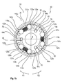
- the inner part 72 has a substantially triangular basic shape with the same leg length of the legs 72a to 72c. Furthermore, in FIG. 5b the stationary in the housing 38 arranged outer part 80 additionally shown. Between the legs 72a to 72c and the inner circular openings 80a of the outer part 80 locking and releasing arrangements 118a to 118c are respectively arranged at equal angular intervals about the rotation axis Z, as best shown in FIG FIG. 5b you can see.
- the elements of the individual locking and releasing arrangements 118a to 118c are respectively designated with the same reference numeral and a continuous lowercase letter, for the elements of the first locking and releasing arrangement 118a of the letter a, for the elements of the second locking and releasing arrangement 118b of the letter b and for the elements of the third blocking and releasing arrangement 118c the letter c is used. Due to the same construction of the lock and release units 118a to 118c, only the first lock and release unit 118a will be described in detail below. The explanations on the structure and function of the first blocking and enable unit 118a also apply to the further lock and release units 118b and 118c.
- the locking and releasing arrangement 118a comprises a clamping roller 119a, 120a arranged between the leg 72a of the inner part 72 and the circular opening 80a of the outer part 80, a compression spring 121a arranged between the clamping rollers 119a, 120a, a first release element 122a resting on the spring 121a opposite side of the pinch roller 119a and a second release member 123a, which is arranged on the spring 121a opposite side of the pinch roller 120a.
- the cross-sectional area between the leg 72a and the circular opening 80a tapers towards the leg end of the leg 72a, so that the lateral surfaces of the pinch rollers 119a, 120a in the in FIG. 5b shown position on both the inside of the circular opening 80a and the outer leg 72a so that it is clamped upon rotation of the inner part 72 in the first rotational direction R1, the pinch roller 119a between the leg 72a and the circular opening 80a.
- the pinch roller 120a Upon rotation of the inner part 72 in the opposite second rotational direction R2, the pinch roller 120a is clamped between the circular opening 80a and the leg 72a. Thus, a rotation of the inner part 72 relative to the stationary outer part 80 by the clamping rollers 119a, 120a is prevented.
- the portion between the leg 72a and the circular opening 80a in which the roller 119a is disposed becomes a second clamping portion as the first clamping portion 124a and the portion between the leg 72a and the circular opening 80a in which the second pinch roller 120a is disposed Designated 125a.
- the outer part 80, the inner part 72 and the first pinch roller 118a thus form a first locking unit and the outer part 80, the inner part 72 and the second clamping roller 125a form a second locking unit, wherein the first locking unit with the pinch roller 119a a rotation prevents the inner part in the direction of rotation R1 and prevents the locking unit with the pinch roller 120a rotation of the inner part 72 in the rotational direction R2.
- the pinch rollers 119a, 120a are pressed by means of the spring 120a into their respective clamping region 124a, 125a. If a driven-side torque is applied to the output shaft 55, which is introduced in particular into the setting unit 30 via the foot receptacle 18 and is transmitted from the telescopic tubes 51a, 51b to the output shaft 55, the blocking and releasing arrangements 118a to 118c block a rotational movement, so that a rotation of the foot 18 is reliably prevented.
- the second handwheel 36 is rotated, so that rotation of the entraining pins 64a to 64c about the rotation axis Z takes place via the rotation body 62. Since the driving pins 64a to 64c, as already mentioned, are accommodated in the respective bore 70a to 70c with play, rotation of the driving pins 64a to 64c takes place in a first angular range around the axis of rotation Z, without the inner part 72 being rotated.
- the first rotation star 76 is rotated with the release pins 122a, 122b and 122c in the direction of rotation R1 so that the release pin 122a is moved from a neutral position to a release position while contacting the pinch roller 119a and from their clamping area 124a presses.
- the pinch roller 119a can no longer lock the rotation of the inner part 72.
- the movement of the inner part 72 in the direction of rotation R1 is thus released, so that in a further rotation of the driving pins 64a to 64c in the direction of rotation R1 they contact the walls of the holes 70a to 70c and rotate the inner part 72 together with the drive shaft 55.
- rotation star 76 thus in the direction of rotation R1 backlash with the driving pins 64a to 64c into engagement or with much less Game engaged when the driving pins 64a to 64c and the holes 70a to 70c are engaged.
- the output shaft 55 integrally formed integrally with the inner member 72 is rotated, so that the telescopic tubes 51a, 51b and the positioning head 42 disposed at the front end of the inner telescopic tube 51a are rotated together with the inner member 72.
- the pinch roller 119a is pushed back into the clamping area 124a by the spring force of the spring 121a, whereby the release element 122a is moved back to its neutral position, so that rotation of the inner part 72 in the direction of rotation R1 through the Pinch roller 119a subsequently safely avoided, even if a torque is transmitted to the rotation of the inner part 72 in the direction of rotation R1 on the foot 10.
- the release member 122a moves backward, the rotary star 76 is rotated in the second rotational direction R2 so that all release members 122a-122c connected to the rotary star 76 are moved back to their neutral position.
- the rotational movement is transmitted substantially free of play via the rotary body 62 to the driving pins 64a to 64c, which are rotated in the direction of rotation R2 about the axis of rotation Z around.
- the driving pins 64a to 64c are received with clearance in the bores 70a to 70c of the inner part 72, so that the driving pins 64a to 64c can be rotated in the rotational direction R2 by an angle until they abut the walls of the bores 70a to 70c and exert a driving torque on the inner part 72.
- the follower pins 64a to 64c rotate about the second rotation star 86 in the direction of rotation R2 so that the release member 123a contacts the pinch roller 120a and pushes against the spring force of the spring 121a out of the clamp portion 125a
- Inner part 72 ansch manend in the direction of rotation R2 can be rotated without the pinch roller 120a is clamped in the space between the leg 72a and the circular opening 80a of the outer part 80.
- a rotation of the inner part 72 and thus the output shaft 55 and connected to the output shaft 55 telescopic tube assembly 55 in the direction of rotation R2 by mere actuation of the second handwheel 36 is possible.
- both pinch rollers 119a, 120 are moved simultaneously out of their clamping areas 124a, 125a by means of the release elements 122a, 123a, so that a rotational movement of the inner part 72 is released and the inner part 72 and all elements 55, 51a, non-rotatably connected to the inner part 72, 51b, 42, 44, 18 both on the second handwheel 36 as well as on the output shaft 55, in particular on the foot 18, acting torque can be freely rotated in both directions of rotation R1 and R2.
- the actuating element 54 via the axially displaceable pins 56a to 56c with the rotation release disk 66 engages (see pin 56a in the FIGS. 5a . 5c ) and urge the rotation release disc 66 toward the inner member 72, whereby the rotation release disc 66 simultaneously rotates the first rotation star 76 in the direction of rotation R1 and the second rotation star 86 in the direction of rotation R2, whereby the release pins 122a to 122c, 123a to 123c connected to the rotation stars 76, 86 simultaneously moved from their neutral positions to their release positions and thereby press the pinch rollers 119a to 119c and 120a to 120c simultaneously from their clamping portions 124a to 124c, 125a to 125c.
- pinch rollers 119a to 119c, 120a to 120c are automatically moved back into their clamping portions 124a to 124c, 125a to 125c, so that rotation of the inner member 72 by a driven side torque again easily and securely prevented by the lock and release assemblies 118a to 118c becomes.
- FIG. 6 shows a perspective view of a cross section of the rotary drive 53 and the housing 38 along the section line AA after FIG. 5a ,
- Figure 7a is another view of elements of the rotary drive 53 in a partially sectioned view, similar to the FIG. 5a , wherein the elements of the rotary drive 53 opposite FIG. 5a are shown in a different angular position. Furthermore, in Figure 7a in addition, the hub 37 of the second handwheel 36 without the three shown to rotate the hub 37 in this screw lever.
- the three pins 56a to 56c project through the hub 37 and further extend through the rotary body 62. As a result, the pins 56a to 56c transmit a rotary movement of the hand wheel 36 to the rotary body 62.
- the pins 56a to 56c are arranged at equal angular intervals about the axis of rotation Z.
- the driving pins 64a to 64c fixedly connected to the rotating body 62 are arranged on another circular path or offset from the pins 56a to 56c at equal angular intervals about the rotation axis Z.
- the rotary motion transmitted from the second handwheel 36 via the pins 56a to 56c to the rotary body 62 is transmitted without play to the follower pins 64a to 64c, which then as described the position of the release members 123a to 123c, 124a to 124c depending on the rotational direction R1 , R2 move from a neutral position to a release position and then rotate the inner part 72.
- the pins 56a to 56c also serve to couple the actuator 54 to the rotational release disc 66 by displacing the pins 56a to 56c in the axial direction toward the rotation stars 76,86 by the actuator 54 and rotating the rotational disc 66 in the direction of rotation Rotation stars 76, 86 shifts.
- FIG. 7b is a sectional view of the in Figure 7a shown arrangement with elements of the rotary drive 53 along the section line AA after Figure 7a shown.
- FIG. 7b neither the outer part 80 nor the housing 38 are shown.
- FIG. 8 shows a further perspective view of an arrangement with elements of the rotary drive 53, in which the elements for releasing an independent of the operation of the second handwheel 36 rotational movement of the output shaft 55 are clearly visible.
- the pins 56a to 56c are displaced in the direction of the rotation stars 76, 86 upon actuation of the actuating element 54
- the rotation release disk 66 has rotational release members 66a to 66c protruding thereon in the direction of the rotation stars 76, 86, and the portions 88a formed between arms 86a to 86c and 76a to 76c of the rotation stars 76, 86 are pushed to 88c z and thereby rotate the rotating stars 76, 86 against each other, so that all release elements 122a to 122c, 123a to 123c are simultaneously moved from its neutral position to its release position.
- the actuation of the actuating element 54 by pulling the actuating element in the direction of the first handwheel 36 and Direction of the rear end of the setting 30 done. More specifically, the rotation release disk 66 is turned so that the rotation release members 66a to 66c project toward the operation member 54. Further, the rotation release disk 66 is then placed between the inner part 72 and the rotation stars 76, 86.
Landscapes
- Health & Medical Sciences (AREA)
- Engineering & Computer Science (AREA)
- Life Sciences & Earth Sciences (AREA)
- Public Health (AREA)
- Veterinary Medicine (AREA)
- Biomedical Technology (AREA)
- Animal Behavior & Ethology (AREA)
- General Health & Medical Sciences (AREA)
- Orthopedic Medicine & Surgery (AREA)
- Surgery (AREA)
- General Engineering & Computer Science (AREA)
- Nuclear Medicine, Radiotherapy & Molecular Imaging (AREA)
- Heart & Thoracic Surgery (AREA)
- Medical Informatics (AREA)
- Molecular Biology (AREA)
- Mechanical Engineering (AREA)
- Oral & Maxillofacial Surgery (AREA)
- Pathology (AREA)
- Neurosurgery (AREA)
- Accommodation For Nursing Or Treatment Tables (AREA)
- Surgical Instruments (AREA)
- Infusion, Injection, And Reservoir Apparatuses (AREA)
Abstract
Description
- Die Erfindung betrifft eine Vorrichtung zum selbsthemmenden bidirektionalem Antrieb einer medizinischen Behandlungsvorrichtung, mit einem um eine Drehachse drehbaren Innenteil, einem rotationsfesten Außenteil mit einer kreisförmigen Öffnung, die das Innenteil umgibt und konzentrisch um die Drehachse angeordnet ist, einer um die Drehachse drehbaren Abtriebswelle, die mit dem Innenteil und mit der Behandlungsvorrichtung verbindbar ist und mit einem Antriebselement zum Drehen des Innenteils zusammen mit der Abtriebswelle. Ferner umfasst die Vorrichtung einen ersten Klemmkörper und einen zweiten Klemmkörper, die in einem Zwischenraum zwischen dem Innenteil und dem Außenteil angeordnet sind.
- Bei der Behandlung von Patienten ist es oft erforderlich, dass Teile des Patienten, insbesondere Gliedmaßen fixiert und gezielt bewegt werden müssen. Insbesondere bei Operationen, bei denen die Lage eines Körperteils mehrfach gezielt geändert werden muss, sind einstellbare Behandlungsvorrichtungen erforderlich. So muss ein Patientenbein bei einer hüftprothetischen Prozedur nach dem "direct interior approach" sowie bei der "total hip arthroplasty" wiederholt rotiert werden. Das Patientenbein ist hierbei in einer Traktions- bzw. Zugeinheit freitragend gerade eingespannt. Solche Traktions- bzw. Zugeinheiten werden in Verbindung mit Operationstischen auch als Extensionsvorrichtungen bezeichnet. Dabei muss der Rotationswinkel des Beins entsprechend dem chirurgischen Workflow und den medizinischen Notwendigkeiten mehrfach geändert werden. Der maximale übliche Rotationsbereich beträgt 180°.
- Zum Ändern des Rotationswinkels eines in einer Extensionsvorrichtung eingespannten Patientenbeins muss ein Bediener eine Klemmschraube zur Freigabe der Rotation öffnen, sodass die Rotation des Patientenbeins durch die Extensionsvorrichtung freigegeben ist. Anschließend dreht der Operateur das Patientenbein in die gewünschte Position. Dabei kann die Fußspitze des Patienten als Indikator für den Drehwinkel genutzt werden. Das Patientenbein muss dann im gewünschten Rotationswinkel manuell gehalten werden, wobei durch die anatomische Struktur des Beins eine Rückstellkraft in einem von dem gewünschten Rotationswinkel abweichenden Rotationswinkel auftritt. Anschließend wird die Klemmschraube angezogen, sodass das Patientenbein von der Extensionsvorrichtung in dem gewünschten Rotationswinkel fixiert wird. Um das Patientenbein in die vorherige Lage zurückzubringen oder in einen anderen Rotationswinkel zu bringen, muss die Klemmschraube wieder geöffnet werden, das Patientenbein wieder kontrolliert zurück oder in die gewünschte Lage gedreht werden. Anschließend wird die Klemmschraube wieder fixiert.
- Abhängig vom chirurgischen Workflow muss diese Prozedur während einer Operation mehrfach wiederholt werden. Im erläuterten Ablauf sind die Tätigkeiten Lösen/Festziehen der Klemmschraube und Rotieren/Halten des Patientenbeins in der gewünschten Position teilweise gleichzeitig durchzuführen. Das Rückstellbestreben des Patientenbeins in eine definierte Lage ist dabei oft erschwerend und führt zu einer erheblichen Belastung des Operateurs, da erhebliche Kraft und Konzentration zur Koordination der erforderlichen Arbeitsschritte benötigt werden. Eine feinfühlige Positionierung des Patientenbeins ist damit während einer Operation nur eingeschränkt möglich, sodass hierdurch ein Risiko für den Patienten im Operationsablauf gegeben ist. Um dieses Risiko in Grenzen zu halten, ist es üblich, dass eine Person die Klemmschraube öffnet und schließt und eine zweite Person das Patientenbein in die gewünschte Lage bringt und dort hält, bis die Klemmschraube wieder festgestellt ist. Mit zwei Personen ist der Aufwand hierfür relativ hoch.
- Aufgabe der Erfindung ist es, eine Vorrichtung anzugeben, mit der die Position einer medizinischen Behandlungsvorrichtung einfach und sicher geändert werden kann.
- Diese Aufgabe wird durch eine Vorrichtung zum selbsthemmenden bidirektionalen Antrieb einer medizinischen Behandlungsvorrichtung mit den Merkmalen des Anspruchs 1 gelöst. Vorteilhafte Weiterbildungen der Erfindung sind in den abhängigen Ansprüchen angegeben.
- Durch die in entgegengesetzte Drehrichtungen wirkenden Sperreinheiten zum Sperren der Drehung des Innenteils wird eine Drehung der Abtriebswelle und somit auch eine Drehung einer mit der Abtriebswelle verbundenen Behandlungsvorrichtung, wie einer Fußaufnahme zur Aufnahme des Fußes eines Patientenbeins verhindert, wenn ein abtriebsseitiges Drehmoment anliegt. Eine Drehung des Innenteils und somit der Abtriebswelle ist durch die erfindungsgemäße Vorrichtung zum selbsthemmenden bidirektionalen Antrieb einer medizinischen Behandlungsvorrichtung nur durch das Antriebselement möglich, da dieses das erste Freigabeelement zur Freigabe der ersten Drehrichtung sowie das zweite Freigabeelement zur Freigabe der zweiten Drehrichtung bewegt. Dadurch ist einfach eine Drehung der Abtriebswelle und somit eine Verstellung der medizinischen Behandlungsvorrichtung durch Betätigen des Antriebselements möglich, wodurch eine einfache Handhabung der medizinischen Behandlungsvorrichtung, insbesondere eine Bedienung durch nur eine Person, einfach möglich ist. Insbesondere kann auf separat zu betätigende Klemm- oder Feststellelemente verzichtet werden, da eine Feststellung automatisch über die in entgegengesetzte Drehrichtungen wirkenden Sperreinheiten sichergestellt ist. Auch ist über das Antriebselement eine exakte Drehung der Abtriebswelle einfach möglich, sodass sich gewünschte Winkelpositionen der Abtriebswelle und der mit der Abtriebswelle verbundenen Behandlungsvorrichtung einfach einstellen lassen.
- Besonders vorteilhaft ist, wenn zusätzlich ein Drehspindelantrieb vorgesehen ist, durch den die medizinische Behandlungsvorrichtung in Richtung der Drehachse oder parallel zur Drehachse verschiebbar ist. Dadurch kann die medizinische Behandlungsvorrichtung entlang der Drehachse bzw. parallel zur Drehachse längs verschoben und zusätzlich der Rotationswinkel der Behandlungsvorrichtung mit Hilfe des Antriebselements exakt eingestellt werden, um z. B. eine Zugkraft auf das Patientenbein auszuüben. Die Drehspindel des Drehspindelantriebs ist vorzugsweise durch die Abtriebswelle mittig hindurchgeführt, wobei die Drehspindel frei drehbar zur Abtriebswelle angeordnet ist.
- Besonders vorteilhaft ist es, wenn das Antriebselement bei einer Drehung in die erste Drehrichtung zuerst das erste Freigabeelement aus einer ersten Neutralposition in die erste Freigabeposition bewegt, in der das erste Freigabeelement das Sperren der Drehung des Innenteils in der ersten Drehrichtung durch die erste Sperreinheit verhindert, und bei einer weiteren Drehung das Innenteil in die erste Drehrichtung dreht. Ferner bewegt das Antriebselement bei einer Drehung in die zweite Drehrichtung zuerst das zweite Freigabeelement aus einer zweiten Neutralposition in die zweite Freigabeposition, in der das zweite Freigabeelement das Sperren der Drehung des Innenteils in der zweiten Drehrichtung durch die zweite Sperreinheit verhindert, und bei einer weiteren Drehung in der zweiten Drehrichtung das Innenteil in die zweite Drehrichtung dreht. Somit erfolgt bei einer Drehung des Antriebselements in die erste Drehrichtung zuerst eine Freigabe der Drehung des Innenteils in der ersten Drehrichtung bzw. das Aufheben des Sperrens der Drehung des Innenteils in der ersten Drehrichtung und anschließend die Drehung des Innenteils und der mit dem Innenteil gekoppelten Abtriebswelle. In gleicher Weise erfolgt bei einer Drehung des Antriebselements in die zweite Drehrichtung zuerst eine Freigabe der Drehung des Innenteils in der zweiten Drehrichtung und bei einer weiteren Drehbewegung des Antriebselements in der zweiten Drehrichtung eine Drehung des Innenteils in die zweite Drehrichtung. Vorzugsweise werden das erste Freigabeelement und das zweite Freigabeelement aus der ersten Freigabeposition bzw. zweiten Freigabeposition automatisch zurück in die erste bzw. zweite Neutralposition, vorzugsweise durch eine Federkraft aus der jeweiligen Freigabeposition in die Neutralposition, bewegt. Dadurch ist eine einfache Handhabung der Vorrichtung ohne Umschaltung der gewünschten Drehrichtung oder Entriegelung möglich.
- Ferner ist es vorteilhaft, wenn der erste Klemmkörper in einem zwischen dem Außenteil und dem Innenteil gebildeten ersten Klemmbereich bei einer Drehung des Innenteils in die erste Drehrichtung einklemmbar ist, und wenn der zweite Klemmkörper in einen zwischen dem Außenteil und dem Innenteil gebildeten zweiten Klemmbereich bei einer Drehung des Innenteils in die zweite Drehrichtung einklemmbar ist. Das Einklemmen des ersten Klemmkörpers im ersten Klemmbereich bzw. des zweiten Klemmkörpers im zweiten Klemmbereich erfolgt nur dann, wenn sich das erste Freigabeelement bzw. das zweite Freigabeelement nicht in ihrer Freigabeposition befinden. Durch das Verklemmen der Klemmkörper im zweiten Klemmbereich wird sichergestellt, dass eine Sperrung der Drehbewegung in die erste Drehrichtung und in die zweite Drehrichtung nur dann erfolgt, wenn die Freigabeelemente nicht mit Hilfe der Antriebseinheit in ihre Freigabeposition bewegt worden sind. Somit wird eine Drehung der Abtriebswelle über die medizinische Behandlungsvorrichtung einfach und wirkungsvoll vermieden, ohne dass hierfür bestimmte Bedienhandlungen, wie das Feststellen von Klemmschrauben oder Ähnliches, erforderlich sind. Solche Klemmanordnungen mit Klemmkörpern, die zwischen einem Außenteil und einem Innenteil angeordnet sind und die in einem zwischen Außenteil und Innenteil gebildeten Klemmbereich eingeklemmt werden, sind beispielsweise aus sogenannten Klemmkörperfreiläufen bekannt, die eine freie Drehung eines Innenteils und zu einem Außenteil in einer ersten Drehrichtung ermöglichen und die eine Verbindung zwischen Innen- und Außenteil bei den Drehungen die entgegengesetzte Drehrichtung herstellen.
- Durch das Klemmen der Klemmkörper im entsprechenden Klemmbereich ist eine einfache und nahezu wartungsfreie Anordnung gegeben, die eine ungewünschte Rotation der medizinischen Behandlungsvorrichtung um die Drehachse sicher verhindert.
- Weiterhin ist es vorteilhaft, wenn ein elastisch verformbares Element zwischen dem ersten Klemmkörper und dem zweiten Klemmkörper angeordnet ist, das den ersten Klemmkörper in den ersten Klemmbereich und den zweiten Klemmkörper in den ersten Klemmbereich drückt. Dadurch sind die Klemmkörper sicher im jeweiligen Klemmbereich angeordnet, sodass eine spielfreie Sperrung der Drehbewegung möglich ist und dadurch eine dauerhafte exakte Positionierung der medizinischen Behandlungsvorrichtung erreicht wird.
- Besonders vorteilhaft ist es, wenn das elastische Element eine Feder, vorzugsweise eine zwischen den Klemmkörpern angeordnete Spiralfeder, ist. Alternativ kann das elastisch verformbare Element durch einen Elastomerblock oder Polymerblock gebildet sein. Durch diese Elemente kann auf einfache Weise sichergestellt werden, dass die Klemmkörper in ihren jeweiligen Klemmbereich gedrückt und dort sicher gehalten werden. Ferner kann der jeweilige Klemmkörper bei der Bewegung des jeweiligen Freigabeelements in die Freigabeposition gegen die Federkraft aus dem Klemmbereich gedrückt werden, sodass die Bewegung durch den jeweiligen Klemmkörper nicht mehr gesperrt ist.
- Ferner ist es vorteilhaft, wenn das erste Freigabeelement auf der dem elastisch verformbaren Element abgewandten Seite des ersten Klemmkörpers und das zweite
- Freigabeelement auf der dem elastisch verformbaren Element abgewandten Seite des zweiten Klemmkörpers angeordnet sind. Dadurch ist eine einfache und kompakte Anordnung der Klemmkörper und der Freigabeelemente möglich.
- Ferner ist es vorteilhaft, wenn die erste Sperreinheit und die zweite Sperreinheit bei einem an der Abtriebswelle und/oder an dem Innenteil anliegenden abtriebsseitigen Drehmoment eine Drehung des Innenteils und der Abtriebswelle ohne Betätigung des Antriebselements verhindern. Dadurch ist eine einfachere und sichere Handhabung der Behandlungsvorrichtung ermöglicht, da auch bei einem an dem Innenteil anliegenden abtriebsseitigen Drehmoment eine Drehung des Innenteils und der Abtriebswelle ohne Betätigung des Antriebselements sicher verhindert wird. Somit ist eine einfachere und sichere Handhabung der Behandlungsvorrichtung möglich.
- Ferner ist es vorteilhaft, wenn die Vorrichtung eine Drehung der Abtriebswelle nur durch Betätigen des Antriebselements ermöglicht. Damit ist sichergestellt, dass eine Drehung der medizinischen Behandlungsvorrichtung durch ein abtriebsseitiges Drehmoment sicher verhindert und somit eine sichere Handhabung der medizinischen Behandlungsvorrichtung möglich ist.
- Ferner ist es vorteilhaft, wenn das Antriebselement über mindestens ein Eingriffselement mit dem Innenteil in Eingriff steht, wobei das Eingriffselement in einer Aussparung des Innenteils mit Spiel aufgenommen ist und/oder wobei das Eingriffselement in einer Aussparung des Antriebselements mit Spiel aufgenommen ist. Das Spiel hat vorzugsweise einen Wert im Bereich von 0,5 mm bis 5 mm oder von 0,01° bis 2°.
- Konkret kann das Eingriffselement als Stift und die Aussparung als Bohrung ausgeführt sein, wobei der Stift in die Bohrung ragt und der Durchmesser der Bohrung vorzugsweise um einen Wert im Bereich von 0,5 mm bis 5 mm größer als der Durchmesser des Stifts ist.
- Das Antriebselement ist dabei vorzugsweise direkt, d. h. ohne Spiel, mit den Freigabeelementen gekoppelt bzw. steht direkt ohne Spiel mit diesen in Eingriff. Dadurch kann auf einfache Weise sichergestellt werden, dass zuerst das erste Freigabeelement in die erste Freigabeposition gebracht wird, sodass das Sperren der ersten Sperreinheit verhindert wird, und dass anschließend eine Drehung des Innenteils in die erste Drehrichtung erfolgt. In gleicher Weise wird bei einer Drehung der Antriebseinheit in die zweite Drehrichtung zuerst das zweite Freigabeelement in die zweite Freigabeposition bewegt, in der das zweite Freigabeelement ein Klemmen des zweiten Klemmkörpers im zweiten Klemmbereich verhindert, und anschließend erfolgt eine Drehung des Innenteils durch die Antriebseinheit in der zweiten Drehrichtung. Dadurch ist weder eine Drehrichtungsumschaltung noch eine zusätzliche Arretierung erforderlich. Es muss lediglich ein Antrieb mit Hilfe des Antriebselements erfolgen, um die gewünschte Drehbewegung in einer Bedienhandlung freizugeben und auszuführen.
- Besonders vorteilhaft ist es, wenn das erste Freigabeelement und das zweite Freigabeelement mit einem Betätigungselement in Wirkverbindung stehen, und wenn das Betätigungselement bei einer Betätigung das erste Freigabeelement in die erste Freigabeposition und das zweite Freigabeelement in die zweite Freigabeposition bewegt. Dadurch kann die Sperrung durch die erste Sperreinheit und die Sperrung durch die zweite Sperreinheit gleichzeitig unabhängig von der Betätigung des Antriebselements aufgehoben werden, sodass dann eine Drehung der Abtriebswelle und der mit der Abtriebswelle verbundenen medizinischen Behandlungsvorrichtung auch abtriebsseitig erfolgen kann. Somit erfolgt eine Freigabe der Rotation durch Betätigung des Betätigungselements. Durch die Freigabe der Rotation kann die medizinische Behandlungsvorrichtung frei gedreht werden, beispielsweise um die Funktion und Beweglichkeit von Gelenken einer mit der Behandlungsvorrichtung verbundenen Gliedmaße eines Patienten zu beurteilen, wie beispielsweise die Drehung eines Patientenbeins nach dem Einsetzen einer Hüftendoprothese oder eines künstlichen Kniegelenks.
- Weiterhin ist es vorteilhaft, wenn eine erste Sperr- und Freigabeanordnung zumindest die erste Sperreinheit, die zweite Sperreinheit, die erste Freigabeeinheit und die zweite Freigabeeinheit umfasst und wenn die Vorrichtung mindestens eine zweite Sperr- und Freigabeanordnung umfasst, wobei der Aufbau und die Funktion der zweiten Sperr- und Freigabeanordnung mit dem Aufbauen der ersten Sperr- und Freigabeanordnung übereinstimmen. Somit kann die zweite Sperr- und Freigabeanordnung zumindest eine dritte Sperreinheit, eine vierte Sperreinheit, eine dritte Freigabeeinheit und eine vierte Freigabeeinheit umfassen. Die mindestens zwei Sperr- und Freigabeanordnungen sind in gleichen Winkelabständen um die Drehachse herum angeordnet. Dadurch werden die zwischen Außenteil und Innenteil zum Sperren der Bewegung auftretenden Kräfte gleichmäßig auf den Umfang des Innenteils und Außenteils verteilt, sodass die auf das Innenteil durch die Sperr- und Freigabeanordnungen orthogonal zur Drehachse wirkende Kräfte in der Summe vorzugsweise Null sind. Dadurch müssen weder das Innenteil noch die Abtriebswelle Querkräfte durch die Sperr- und Freigabeanordnungen aufnehmen, wo ein einfacher und kompakter Aufbau möglich ist Besonders vorteilhaft ist es, wenn die Vorrichtung drei Sperr- und Freianordnungen umfasst, deren Aufbau und Funktion übereinstimmen und die in gleichen Winkelabständen um die Drehachse herum angeordnet sind. Dadurch ist ein besonders einfacher und kompakter Aufbau möglich.
- Besonders vorteilhaft ist es, wenn die erste Sperr- und Freigabeanordnung zumindest das erste Freigabeelement, das zweite Freigabeelement, den ersten Klemmkörper und den zweiten Klemmkörper umfasst, wenn die zweite Sperr- und Freigabeanordnung zumindest ein drittes Freigabeelement, ein viertes Freigabeelement, einen dritten Klemmkörper und einen vierten Klemmkörper umfasst, wenn die dritte Sperr-und Freigabeanordnung zumindest ein fünftes Freigabeelement, ein sechstes Freigabeelement, einen fünften Klemmkörper und einen sechsten Klemmkörper umfasst, wenn das erste, dritte und fünfte Freigabeelement derart miteinander verbunden sind, dass sie gemeinsam um die Drehachse bewegbar sind, und wenn das zweite, vierte und sechste Freigabelelement derart miteinander verbunden sind, dass sie gemeinsam um die Drehachse bewegbar sind. Das erste, dritte und fünfte Freigabeelement sind gemeinsam relativ zum zweiten, vierten und sechsten Freigabeelement bewegbar, vorzugsweise um einen Winkel im Bereich von 0,5 ° bis 5°. Dadurch ist eine gemeinsame Bewegung des ersten, dritten und fünften Freigabeelements relativ zum zweiten, vierten und sechsten Freigabeelement möglich, sodass eine solche Bewegung mit Hilfe des Betätigungselements erzeugt werden kann, wodurch alle Freigabeelemente gleichzeitig in ihre jeweilige Freigabeposition bewegt werden können und ein Klemmen des jeweiligen Klemmkörpers im jeweiligen Klemmbereich einfach verhindert wird. Dadurch kann die komplette Aufhebung der Sperrwirkung der ersten Sperreinheit und der zweiten Sperreinheit bzw. der entsprechenden Sperreinheiten der weiteren Sperr- und Freigabeanordnungen auf einfache Art und Weise durch ein Betätigen des Betätigungselements erreicht werden.
- Ferner ist es vorteilhaft, wenn das Betätigungselement beim Betätigen das erste, dritte und fünfte Freigabeelement gemeinsam in die erste Drehrichtung und das zweite, vierte und sechste Freigabeelement in die zweite Drehrichtung, derart bewegt, dass das erste Freigabeelement den ersten Klemmkörper kontaktiert und ein Klemmen des ersten Klemmkörpers im ersten Klemmbereich verhindert, dass das zweite Freigabeelement den zweiten Klemmkörper kontaktiert und ein Klemmen des zweiten Klemmkörpers im zweiten Klemmbereich verhindert, dass das dritte Freigabeelement einen dritten Klemmkörper der zweiten Sperr- und Freigabeanordnung kontaktiert und ein Klemmen des dritten Klemmkörpers in einem zwischen dem Innenteil und dem Außenteil gebildeten dritten Klemmbereich verhindert, dass das vierte Freigabeelement einen vierten Klemmkörper der zweiten Sperr- und Freigabeanordnung kontaktiert und ein Klemmen des vierten Klemmkörpers in einem zwischen dem Innenteil und dem Außenteil gebildeten vierten Klemmbereichs verhindert, dass das fünfte Freigabeelement einen fünften Klemmkörper der dritten Sperr-und Freigabeanordnung kontaktiert und ein Klemmen des fünften Klemmkörpers in einem zwischen dem Innenteil und dem Außenteil gebildeten fünften Klemmbereich verhindert, und/oder dass das sechste Freigabeelement einen sechsten Klemmkörper der dritten Sperr- und Freigabeanordnung kontaktiert und ein Klemmen des sechsten Klemmkörpers in einem zwischen dem Innenteil und dem Außenteil gebildeten sechsten Klemmbereich verhindert. Dadurch erfolgt eine einfache komplette Freigabe der Drehung, sodass dann eine Drehung auch aufgrund eines abtriebsseitigen Drehmoments möglich ist. Die Sperrwirkung der jeweiligen Sperreinheiten wird durch eine Betätigung des Betätigungselements somit aufgehoben. Das Betätigungselement kann dabei so ausgebildet sein, das es im betätigten Zustand verbleibt, solange es nicht von einer Bedienperson vom betätigten Zustand in den unbetätigten Zustand bewegt wird. Alternativ kann das Betätigungselement durch eine Rückstellkraft vom betätigten Zustand in den nicht betätigten Zustand zurückbewegt werden. In diesem Fall müsste eine Bedienperson das Betätigungselement im betätigten Zustand halten, solange die Rotation der Abtriebswelle freigegeben sein soll. Das Rückstellen kann durch eine Feder erfolgen.
- Vorzugsweise sind die Klemmkörper als Klemmrollen ausgebildet, deren Längsachsen parallel zur Drehachse angeordnet sind. Die Querschnittsfläche des Innenteils in einer Ebene quer zur Drehachse ist im Wesentlichen die eines gleichschenkligen Dreiecks.
- Das Antriebselement ist vorzugsweise als Handrad ausgebildet, das um die Drehachse herum gedreht wird. Vorzugsweise ist das Handrad direkt mit den Eingriffselementen zum Betätigen der Freigabeelemente und zur Drehung des Innenteils verbunden. Alternativ kann eine Getriebestufe, vorzugsweise mit einer Untersetzung, zwischen dem Handrad und den Eingriffselementen vorgesehen sein.
- Im Ergebnis kann der Operateur durch die Erfindung insbesondere ein mit der medizinischen Behandlungsvorrichtung verbundenes Patientenbein mit Hilfe der Antriebseinheit die gewünschte Richtung drehen und eine gewünschte Winkelposition einstellen, wobei gleichzeitig eine Rückstellbewegung des Patientenbeins automatisch durch die Sperreinheiten verhindert wird. Die Sperreinheiten sind entgegengesetzt wirkend. Das Ermöglichen der ungehemmten Rotation der medizinischen Behandlungsvorrichtung durch Betätigen des Betätigungselements ermöglicht insbesondere eine Funktionskontrolle bei Hüftgelenkoperationen, insbesondere eine Funktionskontrolle einer eingesetzten Hüftendoprothese. Die Umschaltung zwischen der gesperrten Drehung mit Hilfe der Sperreinheiten und die Freigabe mit Hilfe des Bedienelements ist intraoperativ von nur einer Bedienperson, insbesondere dem Operateur, problemlos durch Betätigen des Betätigungselements möglich.
- Durch die automatische Sperrung einer Rückstellbewegung erfolgt eine spürbare Entlastung des Bedieners, insbesondere des Operateurs. Ferner kann dadurch die Präzision der Positionierung der medizinischen Behandlungsvorrichtung in einer gewünschten Winkelposition erhöht werden. Auch die Korrektur des Rotationswinkels um kleine Winkelbeträge ist einfach durch die stufenlose Verstellung und automatische Sperrung der Drehbewegung einfach möglich. Auch das Risiko von ungewollten Positionsänderungen der medizinischen Behandlungsvorrichtung wird durch die automatische Sperrung der Drehbewegung durch die Sperreinheiten verhindert. Der chirurgische Workflow bei einer Operation oder Behandlung eines Patienten wird vereinfacht und beschleunigt, da weniger Handgriffe als bei bekannten Klemmvorrichtungen zum Einstellen der Rotationen der medizinischen Behandlungsvorrichtung notwendig sind.
- Weitere Merkmale und Vorteile der Erfindung ergeben sich aus der nachfolgenden Beschreibung, die die Erfindung anhand von Ausführungsbeispielen im Zusammenhang mit den beigefügten Figuren näher erläutert. Es zeigen:
- Fig. 1
- eine perspektivische Darstellung eines Operationstisches mit einem Extensionsset für Hüftarthroskopie und minimal-invasiver Hüftendoprothetik, das eine Einstelleinheit zur Rotations- und Längenverstellung einer Fußaufnahme umfasst;
- Fig. 2
- eine perspektivische Seitenansicht der Einstelleinheit;
- Fig. 3
- einen Längsschnitt der Einstelleinheit;
- Fig. 4
- eine vergrößerte Darstellung eines Ausschnitts des Längsschnitts nach
Fig. 3 mit Elementen eines Rotationsantriebs; - Fig. 5a
- eine Seitenansicht einer Anordnung von ausgewählten Elementen von Sperr-und Freigabeeinheiten des Rotationsantriebs nach
Fig. 4 ; - Fig. 5b
- eine Schnittdarstellung der Anordnung nach
Fig. 5a entlang der Schnittlinie A-A, wobei zusätzlich ein Außenteil des Rotationsantriebs dargestellt ist; - Fig. 5c
- eine Schnittdarstellung der Anordnung nach
Fig. 5a entlang der Schnittlinie B-B; - Fig. 6
- eine perspektivische Darstellung eines Querschnitts des Rotationsantriebs entlang der in
Fig. 5a angegebenen Schnittlinie A-A; - Fig. 7a
- eine weitere Ansicht einer Anordnung von Elementen des Rotationsantriebs in einer teilgeschnittenen Darstellung;
- Fig. 7b
- ein Querschnitt der Anordnung nach
Fig. 7a entlang der Schnittlinie A-A; - Fig. 8
- eine weitere perspektivische Darstellung von Elementen des Rotationsantriebs, in der Elemente zur Rotationsfreigabe gut sichtbar sind; und
- Fig. 9
- eine Detaildarstellung von Elementen zur Rotationsfreigabe.
-
Figur 1 zeigt eine perspektivische Darstellung einer Anordnung eines Operatonstisches 10 mit einem Extensionsset 17, die vorzugsweise zur Hüftarthroskopie und minimal-invasiver Hüftendoprothetik eingesetzt wird. Der Operationstisch 10 hat einen Opertionstischfuß 12, eine Operationstischsäule 14 und eine Patientenlagerfläche 16. - Das Extensionsset 17 umfasst einen ersten Extensionsholm 26 und einen zweiten Extensionsholm 28, die jeweils mit einem ersten Ende mit dem Operationstisch 10 verbunden sind. An dem gegenüberliegenden zweiten Ende des ersten Extensionsholms 26 ist dieser über eine erste Verbindungseinheit 22 und über eine Einstelleinheit 30 zur Rotations- und Längenverstellung mit einer ersten Fußaufnahme 18 verbunden. Der zweite Extensionsholm 28 ist über eine zweite Verbindungseinheit 22 mit einer zweiten Fußaufnahme 20 verbunden.
- Die erste Fußaufnahme 18 dient zur Aufnahme des Fußes des zu operierenden Patientenbeins und die zweite Fußaufnahme 20 dient zur Aufnahme des Fußes des nicht zu operierenden Patientenbeins. Somit ist eine Einstelleinheit zur Rotations- und Längenverstellung zwischen der zweiten Verbindungseinheit 24 und der zweiten Fußaufnahme 20 nicht erforderlich. Die zweite Fußaufnahme 20 ist über einen Verbindungsstab 32 mit einer zweiten Verbindungseinheit 24 verbunden. Die Verbindungseinheiten 22, 24 sind auf den jeweiligen Extensionsholmen 26, 28 verschiebbar und feststellbar angeordnet, um das Extensionsset 17 an die Patientenstatur anzupassen. Die Einstelleinheit 30 zur Rotations- und Längenverstellung wird auch als Zugspindelaggregat bezeichnet.
- Alternativ kann auch eine Einstelleinheit zwischen der Verbindungseinheit 24 und der Fußaufnahme 20 angeordnet sein, deren Aufbau und Funktion mit dem Aufbau und Funktion der Einstelleinheit 30 übereinstimmt.
-
Figur 2 zeigt eine perspektivische Seitenansicht der Einstelleinheit 30. Die Einstelleinheit 30 hat ein erstes Handrad 34 zur axialen Verschiebung eines Verbindungselements 44 entlang einer Längs- und Drehachse Z der Einstelleinheit 30. Das Verbindungselement 44 dient zum Verbinden der Einstelleinheit 30 mit der ersten Fußaufnahme 18. Die Einstelleinheit 30 umfasst ferner ein zweites Handrad 36 zur Rotationseinstellung des Verbindungselements 44, so dass mit Hilfe des Handrads 36 der Drehwinkel der ersten Fußaufnahme 18 änderbar ist. - In einem Gehäuse der Einstelleinheit 30 ist eine mit den Drehrädern 34, 36 in Wirkverbindung stehende Mechanik angeordnet, mit der das Verbindungselement 44 über einen Positionierungskopf 42 verbunden ist. Über den Positionierungskopf 42 ist die Lage des Verbindungselements 44 um eine Drehachse orthogonal zur Längs- und Drehachse Z der Einstelleinheit 30 schwenkbar. Mit Hilfe eines Klemmverschlusses 46 des Positionierungskopfs 42 ist das Verbindungselement 44 in einer Schwenkposition feststellbar. Über ein Gelenk 40 ist die Einstelleinheit 30 mit einer Gelenkkopfhalterung 41 der Verbindungseinheit 22 verbunden.
-
Figur 3 zeigt einen Längsschnitt einer Einstelleinheit 30. Die Einstelleinheit 30 hat eine mit dem ersten Handrad 34 fest verbundene Antriebsspindel 48, die zum Antrieb einer Teleskoprohranordnung 51 zum axialen Verschieben des Positionierungskopfs 42 dient. Die Teleskoprohranordnung 51 ist in den Figuren in einer eingefahrenen Position dargestellt. Die Teleskoprohranordnung 51 hat ein inneres Teleskoprohr 51a und ein äußeres Teleskoprohr 51b. Das äußere Teleskoprohr 51b ist in einer stirnseitigen Öffnung einer Abtriebswelle 55 eines mithilfe des zweiten Handrads 36 angetriebenen Rotationsantriebs 53 drehfest aufgenommen. Der Aufbau und die Funktion des Rotationsantriebs 53 werden nachfolgend in Verbindung mit den weiteren Figuren noch näher erläutert. - Das dem ersten Antriebsrad 34 zugewandte Ende des inneren Teleskoprohrs 51a ist in einem mithilfe der Antriebsspindel 48 bewegbaren Schlitten 52, dessen Innengewinde 52a mit dem Außengewinde 49 der Antriebsspindel 48 in Eingriff steht, fest verbunden. Der Antriebsschlitten 52 hat eine erste nach oben durch einen im äußeren Teleskoprohr 51b vorhandenen oberen Schlitz hindurchragende Nase 52b und eine nach unten durch einen zweiten unteren Schlitz im äußeren Teleskoprohr 51b hindurchragende Nase 52c. Dadurch wird der Schlitten 52 bei einer Drehung des äußeren Teleskoprohrs 51b mit Hilfe des Rotationsantriebs 53 zusammen mit dem äußeren Teleskoprohr 51b gedreht, so dass somit auch das drehfest mit dem Schlitten 52 verbundene innere Teleskoprohr 51a und der Positionierungskopf 42 zusammen mit dem äußeren Teleskoprohr 51b gedreht wird. Beim Ausfahren des inneren Teleskoprohrs 51a aus dem äußeren Teleskoprohr 51b wird der Positionierungskopf 42 somit unter Beibehaltung seiner Winkelstellung ein- und ausgefahren. Das dem Positionierungskopf 42 zugewandte Ende der Antriebsspindel 48 ist in einem Lager 50 drehbar aufgenommen, wobei die Antriebsspindel 48 derart mit dem Lager 50 verbunden ist, dass das Lager 50 beim Ein- und Ausfahren des inneren Teleskoprohrs 51a an dessen Innenwand entlanggleitet. Das äußere Teleskoprohr 51b ist mit dem der Abtriebswelle 55 gegenüberliegenden Ende in einer in dem Gehäuse 38 ausgebildeten Lagerbuchse aufgenommen, so dass dieses Ende des äußeren Teleskoprohrs 51b sicher gehalten und drehbar relativ zum Gehäuse 38 ist. Die Nasen 52b, 52c des Schlittens 52 stehen mit einem umlaufenden Indikatorring 52d im Eingriff, über den die axiale Position des inneren Teleskoprohrs 51a auf einer von außen durch ein Sichtfenster im Gehäuse 38 sichtbaren Skala 52e angezeigt wird. Durch die Drehung der Antriebsspindel 48 mit Hilfe des ersten Handrads 34 kann das innere Teleskoprohr 51a aus dem äußeren Teleskoprohr 51b herausbewegt und wieder hineinbewegt werden.
- Die Längsachse Z der Einstelleinheit 30 ist zugleich die Mittelachse der Antriebsspindel 48 und der Teleskoprohre 51a, 51b, so dass die Längsachse Z gleichzeitig Drehachse Z ist, um die dann der Positionierungskopf 42 zusammen mit der Fußaufnahme 18 mit Hilfe des Rotationsantriebs 53 drehbar ist.
- Zwischen dem ersten Handrad 34 und dem zweiten Handrad 36 ist ein Betätigungselement 54 angeordnet, bei dessen Betätigung eine Drehung des äußeren Teleskoprohrs 51b zusammen mit dem inneren Teleskoprohr 51a auch ohne eine Drehbewegung des zweiten Handrades 36 ermöglicht. Zum Betätigen des Betätigungselements 54 wird dieses entlang der Drehachse Z in Richtung des Positionierungskopfs 42 verschoben. Der Betätigungshub entlang der Drehachse Z ist durch den Abstand des vom Positionierungskopf 42 abgewandten Ende der Nabe 37 des zweiten Handrads 36 und einem am Betätigungselement 54 vorgesehenen Vorsprung 54a begrenzt. Um eine vom zweiten Handrad 36 unabhängige Drehung zu ermöglichen, steht das Betätigungselement 54 über drei axial verschiebbare Stifte in Eingriff, von denen ein in
Figur 3 sichtbarer Stift mit den Bezugszeichen 56a bezeichnet ist. Die drei Stifte sind in gleichen Winkelabständen um die Drehachse Z angeordnet und sind in den weiteren Figuren auch mit den Bezugszeichen 56a, 56b, 56c bezeichnet. -
Figur 4 zeigt eine vergrößerte Darstellung eines Ausschnitts des Längsschnitts nachFigur 3 mit Elementen des Rotationsantriebs 53. Der Rotationsantrieb 53 umfasst eine Vorrichtung 60 zum selbsthemmenden bidirektionalen Antrieb der Abtriebswelle 55. Das zweite Handrad 36 steht über die Stifte 56a bis 56c mit einem Rotationskörper 62 in Eingriff, so dass eine Drehbewegung des zweiten Handrads 36 auf den Rotationskörper 62 übertragen wird. Der Rotationskörper 62 ist im Gehäuse 38 über ein erstes Kugellager 82 drehbar um die Drehachse Z aufgenommen. Ferner ist der Rotationskörper 62 frei drehbar auf dem dem zweiten Handrad 36 zugewandten Ende der Abtriebswelle 55 angeordnet. Weiterhin sind sowohl das zweite Handrad 36, das Betätigungselement 54 als auch die Abtriebswelle 55 jeweils frei drehbar auf der Antriebsspindel 48 angeordnet. Ferner ist das dem Positionierungskopf 42 zugewandte Ende der Abtriebswelle 55 über ein zweites Kugellager 84 im Gehäuse 38 aufgenommen. Ferner ragen drei fest mit dem Rotationskörper 62 verbundene Mitnahmestifte, von denen inFigur 4 sichtbarer Mitnahmestift mit dem Bezugszeichen 64a und die weiteren in den weiteren Figuren sichtbaren Mitnahmestifte mit den Bezugszeichen 64b und 64c bezeichnet sind, in drei in einem ein Innenteil 72 des Rotationsantriebs 53 bildenden Bereich der Abtriebswelle 55 vorgesehene Bohrungen, von denen die inFigur 4 sichtbare Bohrung mit dem Bezugszeichen 70a und die weiteren in den weiteren Figuren sichtbaren Bohrungen mit den Bezugszeichen 70b und 70c bezeichnet sind. Die Mitnahmestifte 64a bis 64c sind hierbei durch eine Rotationsfreigabescheibe 66 hindurchgeführt, wobei die Rotationsfreigabescheibe 66 in Richtung der Drehachse Z mithilfe der Stifte 56a bis 56c in Richtung des Positionierungskopfs 42 zur Freigabe der Rotation der Abtriebswelle 55 ohne Betätigung des zweiten Handrads 36 verschiebbar ist. - Der Durchmesser der Bohrungen 70a bis 70c ist im vorliegenden Ausführungsbeispiel 2 mm größer als der Durchmesser der Mitnahmestifte 64a bis 64c. Somit sind die Mitnahmestifte 64a bis 64c mit einem Spiel von 2mm, d.h. von 1mm in jede Drehrichtung R1, R2, in den Bohrungen 70a bis 70c aufgenommen, so dass bei einer Drehung des zweiten Handrads 36 im Bereich des Spiels keine Drehung der Abtriebswelle 55 erfolgt. Wie in
Figur 9 gut zu sehen ist, sind die Mitnahmestifte 64a bis 64c dabei zwischen den Armen 76a bis 76c eines ersten Rotationssterns 76 und zwischen den Armen 86a bis 86c eines zweiten Rotationssterns 86 hindurchgeführt, mit denen als Freigabeelemente dienende Freigabestifte fest verbunden sind. Die Längsachsen der Freigabestifte 64a bis 64c sowie die Längsachsen der Mitnahmestifte 64a bis 64c verlaufen parallel zur Drehachse Z. Die mit dem jeweiligen Rotationsstern 76, 86 verbundenen Freigabestifte werden bei einer durch die Drehung der Mitnahmestifte 64a bis 64c im Bereich des zwischen den Bohrungen 70a bis 70c und den Mitnahmestiften 64a bis 64c vorhandenen Spiels gedreht, wobei abhängig von der Drehrichtung der erste Rotationsstern 76 oder der zweite Rotationsstern 86 gedreht wird. Bei einer Betätigung des Betätigungselements 54 wird über die Stifte 56a bis 56c die Rotationsfreigabescheibe 66 in Richtung des Innenteils 72 bewegt, wodurch beide Rotationssterne 76, 86 gleichzeitig in entgegengesetzte Drehrichtungen gedreht werden, wie später in Verbindung mit denFiguren 8 und9 noch näher erläutert wird. Zwischen dem Innenteil 72 und den Rotationssternen 76, 86 ist eine mit Öffnungen zum Durchführen der Mitnahmestifte 64a bis 64c versehene Zwischenscheibe 68 angeordnet. - Der erste Rotationsstern 76 und der zweite Rotationsstern 86 sind auf der Abtriebswelle 55 drehbar um die Drehachse Z gelagert. Um das Innenteil 72 herum ist ein drehfest mit dem Gehäuse 38 verbundenes Außenteil 80 angeordnet, das zumindest im Bereich des Innenteils 72 eine kreisrunde Öffnung 80a hat. Zwischen dem Innenteil 72 und dem Außenteil 80 sind insgesamt sechs Klemmrollen angeordnet, von denen die in
Figur 4 sichtbare Klemmrolle mit dem Bezugszeichen 119a bezeichnet ist. -
Figur 5a zeigt eine Seitenansicht mit einer Anordnung von ausgewählten Elementen des Rotationsantriebs 53 undFigur 5b einen Schnitt der Anordnung nachFigur 5a entlang der Schnittlinie A-A.Figur 5c zeigt eine Schnittdarstellung der Anordnung nachFigur 5a entlang der Schnittlinie B-B. - Das Innenteil 72 hat eine im Wesentlichen dreieckige Grundform mit gleicher Schenkellänge der Schenkel 72a bis 72c. Ferner ist in
Figur 5b das ortsfest im Gehäuse 38 angeordnete Außenteil 80 zusätzlich dargestellt. Zwischen den Schenkeln 72a bis 72c und der inneren kreisrunden Öffnungen 80a des Außenteils 80 sind jeweils in gleichen Winkelabständen um die Drehachse Z Sperr- und Freigabeanordnungen 118a bis 118c angeordnet, wie dies am Besten inFigur 5b zu sehen ist. Die Elemente der einzelnen Sperr- und Freigabeanordnungen 118a bis 118c sind jeweils mit der gleichen Bezugszeichenziffer und einem fortlaufenden Kleinbuchstaben bezeichnet, wobei für die Elemente der ersten Sperr- und Freigabeanordnung 118a der Buchstabe a, für die Elemente der zweiten Sperr- und Freigabeanordnung 118b der Buchstabe b und für die Elemente der dritten Sperr- und Freigabeanordnung 118c der Buchstabe c verwendet wird. Aufgrund des gleichen Aufbaus der Sperr- und Freigabeeinheiten 118a bis 118c wird im Folgenden nur die erste Sperr- und Freigabeeinheit 118a ausführlich beschrieben. Die Erläuterungen zum Aufbau und Funktion der ersten Sperr- und Freigabeeinheit 118a gelten auch für die weiteren Sperr- und Freigabeeinheiten 118b und 118c. - Die Sperr- und Freigabeanordnung 118a umfasst eine zwischen dem Schenkel 72a des Innenteils 72 und der kreisrunden Öffnung 80a des Außenteils 80 angeordnete Klemmrollen 119a, 120a, eine zwischen den Klemmrollen 119a, 120a angeordnete Druckfeder 121a, ein erstes Freigabeelement 122a, das auf der der Feder 121a gegenüberliegenden Seite der Klemmrolle 119a angeordnet ist und ein zweites Freigabeelement 123a, das auf der der Feder 121a gegenüberliegenden Seite der Klemmrolle 120a angeordnet ist. Der Querschnittsbereich zwischen dem Schenkel 72a und der kreisrunden Öffnung 80a verjüngt sich zu dem Schenkelenden des Schenkels 72a hin, so dass die Mantelflächen der Klemmrollen 119a, 120a in der in
Figur 5b gezeigten Position sowohl an der Innenseite der kreisrunden Öffnung 80a als auch am äußeren Schenkel 72a anliegen, so dass sie bei einer Drehung des Innenteils 72 in der ersten Drehrichtung R1 die Klemmrolle 119a zwischen dem Schenkel 72a und der kreisrunden Öffnung 80a eingeklemmt wird. - Bei einer Drehung des Innenteils 72 in die entgegengesetzte zweite Drehrichtung R2 wird die Klemmrolle 120a zwischen der kreisrunden Öffnung 80a und dem Schenkel 72a eingeklemmt. Somit wird eine Drehung des Innenteils 72 gegenüber dem ortsfesten Außenteil 80 durch die Klemmrollen 119a, 120a verhindert. Der Bereich zwischen dem Schenkel 72a und der kreisrunden Öffnung 80a, in dem die Rolle 119a angeordnet ist, wird als erster Klemmbereich 124a und der Bereich zwischen dem Schenkel 72a und der kreisrunden Öffnung 80a, in dem die zweite Klemmrolle 120a angeordnet ist, als zweiter Klemmbereich 125a bezeichnet. Das Außenteil 80, das Innenteil 72 und die erste Klemmrolle 118a bilden somit eine erste Sperreinheit und das Außenteil 80, das Innenteil 72 und die zweite Klemmrolle 125a bilden eine zweite Sperreinheit, wobei die erste Sperreinheit mit der Klemmrolle 119a eine Drehung des Innenteils in der Drehrichtung R1 verhindert und die Sperreinheit mit der Klemmrolle 120a eine Drehung des Innenteils 72 in der Drehrichtung R2 verhindert.
- Die Klemmrollen 119a, 120a werden mithilfe der Feder 120a in ihren jeweiligen Klemmbereich 124a, 125a gedrückt. Liegt ein abtriebsseitiges Drehmoment an der Abtriebswelle 55 an, das insbesondere über die Fußaufnahme 18 in die Einstelleinheit 30 eingeleitet wird und von dem Teleskoprohren 51a, 51b auf die Abtriebswelle 55 übertragen wird, sperren die Sperr- und Freigabeanordnungen 118a bis 118c eine Drehbewegung, so dass eine Rotation der Fußaufnahme 18 sicher verhindert wird.
- Soll jedoch die Rotation der Fußaufnahme 18 aktiv verstellt werden, so wird das zweite Handrad 36 gedreht, so dass über den Rotationskörper 62 eine Drehung der Mitnahmestifte 64a bis 64c um die Drehachse Z herum erfolgt. Da die Mitnahmestifte 64a bis 64c, wie bereits erwähnt, in der jeweiligen Bohrung 70a bis 70c mit Spiel aufgenommen sind, erfolgt eine Drehung der Mitnahmestifte 64a bis 64c in einem ersten Winkelbereich um die Drehachse Z herum, ohne dass das Innenteil 72 mitgedreht wird. Bei einer Drehung der Mitnahmestifte 64a bis 64c in der Drehrichtung R1 wird der erste Rotationsstern 76 mit den Freigabestiften 122a, 122b und 122c in Drehrichtung R1 gedreht, so dass der Freigabestift 122a von einer Neutralpostition in eine Freigabeposition bewegt wird und dabei die Klemmrolle 119a kontaktiert und aus ihrem Klemmbereich 124a drückt. Dadurch kann die Klemmrolle 119a die Drehung des Innenteils 72 nicht mehr sperren. Die Bewegung des Innenteils 72 in Drehrichtung R1 ist somit freigegeben, so dass bei einer weiteren Drehung der Mitnahmestifte 64a bis 64c in Drehrichtung R1 diese die Wandungen der Bohrungen 70a bis 70c kontaktieren und das Innenteil 72 zusammen mit der Antriebswelle 55 drehen. Im Unterschied zum Innenteil 72 steht Rotationsstern 76 somit in Drehrichtung R1 spielfrei mit den Mitnahmestiften 64a bis 64c in Eingriff oder mit wesentlich geringerem Spiel in Eingriff, als die Mitnahmestifte 64a bis 64c und die Bohrungen 70a bis 70c in Eingriff stehen.
- Bei der Drehung des Innenteils 72 wird die einteilig oder einstückig mit dem Innenteil 72 ausgebildete Abtriebswelle 55 gedreht, so dass die Teleskoprohre 51a, 51b und der am vorderen Ende des inneren Teleskoprohrs 51a angeordnete Positionierungskopf 42 zusammen mit dem Innenteil 72 gedreht werden. Wird keine Antriebskraft mehr über das Handrad 36 ausgeübt, wird die Klemmrolle 119a durch die Federkraft der Feder 121a zurück in den Klemmbereich 124a gedrückt, wodurch das Freigabeelement 122a zurück in seine Neutralposition bewegt wird, so dass eine Drehung des Innenteils 72 in Drehrichtung R1 durch die Klemmrolle 119a nachfolgend sicher vermieden wird, auch dann, wenn über die Fußaufnahme 10 ein Drehmoment zur Drehung des Innenteils 72 in Drehrichtung R1 übertragen wird. Beim Zurückbewegen des Freigabeelements 122a wird der Rotationsstern 76 in die zweite Drehrichtung R2 gedreht, so dass alle mit dem Rotationsstern 76 verbundene Freigabeelemente 122a bis 122c zurück in ihre Neutralposition bewegt werden.
- Bei einer Drehung des zweiten Handrads 36 in Drehrichtung R2 wird die Drehbewegung im Wesentlichen spielfrei über den Rotationskörper 62 auf die Mitnahmestifte 64a bis 64c übertragen, die in Drehrichtung R2 um die Drehachse Z herum gedreht werden. Wie bereits erwähnt, sind die Mitnahmestifte 64a bis 64c mit Spiel in den Bohrungen 70a bis 70c des Innenteils 72 aufgenommen, so dass die Mitnahmestifte 64a bis 64c einen Winkelbetrag in Drehrichtung R2 gedreht werden können, bis sie an den Wandungen der Bohrungen 70a bis 70c anstoßen und ein Antriebsdrehmoment auf das Innenteil 72 ausüben. Bei dieser Winkelverstellung innerhalb des Spiels drehen die Mitnahmestifte 64a bis 64c um den zweiten Rotationsstern 86 in Drehrichtung R2, so dass das Freigabeelement 123a die Klemmrolle 120a kontaktiert und gegen die Federkraft der Feder 121a aus dem Klemmbereich 125a drückt, so dass das Innenteil 72 anschießend in Drehrichtung R2 gedreht werden kann, ohne dass die Klemmrolle 120a in dem Zwischenraum zwischen dem Schenkel 72a und der kreisrunden Öffnung 80a des Außenteils 80 eingeklemmt wird. Dadurch ist eine Drehung des Innenteils 72 und somit der Abtriebswelle 55 und der mit der Abtriebswelle 55 verbundenen Teleskoprohranordnung 55 in Drehrichtung R2 durch bloße Betätigung des zweiten Handrades 36 möglich. Wird das zweite Handrad 36 nicht mehr in Drehrichtung R2 gedreht bzw. wird es losgelassen, drückt die Feder 121a die Klemmrolle 120a in den Klemmbereich 125a zurück, wodurch die Klemmrolle 120a das Freigabeelement 123a von der Freigabeposition wieder zurück in seine Neutralposition drückt, wobei der gesamte Rotationsstern 86 in Drehrichtung R1 gedreht wird, bis alle Elemente die in
Figur 5b gezeigte Position haben. In dieser Position wird eine Drehung durch ein auf der Abtriebswelle 55 wirkenden Drehmoments wieder durch die Sperr- und Freigabeeinheiten 118a bis 118c einfach verhindert. Eine Drehung ist somit in dem beschriebenen Rotationseinstellmodus des Rotationsantriebs 53 nur über eine Drehung des zweiten Handrads 36 möglich. Der Rotationsantrieb 53 ist, wie nachfolgend in Verbindung mit denFiguren 8 und9 noch ausführlich beschrieben wird, auch in einem Rotationsfreigabemodus betreibbar, der mithilfe des bereits erwähnten Betätigungselements 54 aktivierbar ist. In diesem Rotationsfreigabemodus werden mithilfe der Freigabeelemente 122a, 123a beide Klemmrollen 119a, 120 gleichzeitig aus ihren Klemmbereichen 124a, 125a bewegt, so dass eine Drehbewegung des Innenteils 72 freigegeben ist und das Innenteil 72 und alle drehfest mit dem Innenteil 72 verbundenen Elemente 55, 51a, 51b, 42, 44, 18 sowohl über das zweite Handrad 36 als auch über ein auf die Abtriebswelle 55, insbesondere über die Fußaufnahme 18, wirkendes Drehmoment frei in beide Drehrichtungen R1 und R2 gedreht werden können. - Hierzu steht das Betätigungselement 54 über die axial verschiebbaren Stifte 56a bis 56c mit der Rotationsfreigabescheibe 66 in Eingriff (siehe Stift 56a in den
Figuren 5a ,5c ) und drücken die Rotationsfreigabescheibe 66 zum Innenteil 72 hin, wodurch die Rotationsfreigabescheibe 66 gleichzeitig den ersten Rotationsstern 76 in Drehrichtung R1 und den zweiten Rotationsstern 86 in Drehrichtung R2 dreht, wodurch die mit dem Rotationssternen 76, 86 verbundenen Freigabestifte 122a bis 122c, 123a bis 123c gleichzeitig von ihren Neutralpositionen in ihre Freigabepositionen bewegt und dadurch die Klemmrollen 119a bis 119c und 120a bis 120c gleichzeitig aus ihren Klemmbereichen 124a bis 124c, 125a bis 125c drücken. Über eine zwischen den Rotationssternen 76, 86 und der Rotationsfreigabescheibe 66 angeordnete Federn 74a, 74b und74c, von denen inFigur 5a nur die Feder 74a sichtbar ist, wird eine Rückstellkraft zum Zurückstellen des Betätigungselements 54 in die inFigur 4 gezeigte Position bewirkt, so dass dann, wenn das Betätigungselement 54 nicht mehr betätigt ist, die Rotationsfreigabescheibe 66 und das über die Stifte 56a bis 56c verbundene Betätigungselement 54 zurückbewegt wird und eine Rückstellung der Freigabeelemente 122a bis 122c, 123a bis 123c durch die Federkraft der Federn 121a bis 121c erfolgt. Dadurch werden die Klemmrollen 119a bis 119c, 120a bis 120c automatisch zurück in ihre Klemmbereiche 124a bis 124c, 125a bis 125c bewegt, so dass eine Drehung des Innenteils 72 durch ein abtriebsseitiges Drehmoment wieder einfach und sicher durch die Sperr- und Freigabeanordnungen 118a bis 118c verhindert wird. -
Figur 6 zeigt eine perspektivische Darstellung eines Querschnitts des Rotationsantriebs 53 und durch das Gehäuse 38 entlang der Schnittlinie A-A nachFigur 5a . - In
Figur 7a ist eine weitere Ansicht von Elementen des Rotationsantriebs 53 in einer teilgeschnittenen Darstellung, ähnlich der nachFigur 5a , wobei die Elemente des Rotationsantriebs 53 gegenüberFigur 5a in einer anderen Winkelstellung dargestellt sind. Ferner sind inFigur 7a zusätzlich die Nabe 37 des zweiten Handrads 36 ohne die drei zum Drehen der Nabe 37 in diese einschraubbare Hebel dargestellt. - Die drei Stifte 56a bis 56c ragen durch die Nabe 37 hindurch und erstrecken sich weiter durch den Rotationskörper 62 hindurch. Dadurch übertragen die Stifte 56a bis 56c eine Drehbewegung des Handrads 36 auf den Rotationskörper 62. Die Stifte 56a bis 56c sind in gleichen Winkelabständen um die Drehachse Z angeordnet. Die mit dem Rotationskörper 62 fest verbundenen Mitnahmestifte 64a bis 64c sind auf einer anderen Kreisbahn oder versetzt zu den Stiften 56a bis 56c in gleichen Winkelabständen um die Drehachse Z herum angeordnet. Somit wird die von dem zweiten Handrad 36 über die Stifte 56a bis 56c auf den Rotationskörper 62 übertragene Drehbewegung ohne Spiel auf die Mitnahmestifte 64a bis 64c übertragen, die dann wie beschrieben die Position der Freigabeelemente 123a bis 123c, 124a bis 124c abhängig von der Drehrichtung R1, R2 aus einer Neutralstellung in eine Freigabestellung bewegen und anschließend das Innenteil 72 drehen. Wie bereits erwähnt, dienen die Stifte 56a bis 56c auch zur Kopplung des Betätigungselements 54 mit der Rotationsfreigabescheibe 66, indem die Stifte 56a bis 56c durch das Betätigungselement 54 in axialer Richtung zu den Rotationssternen 76, 86 hin verschoben werden und die Rotationsfreigabescheibe 66 in Richtung der Rotationssterne 76, 86 verschiebt.
- In
Figur 7b ist eine Schnittdarstellung der inFigur 7a gezeigten Anordnung mit Elementen des Rotationsantriebs 53 entlang der Schnittlinie A-A nachFigur 7a dargestellt. Sowohl inFigur 7a als auch inFigur 7b sind weder das Außenteil 80 noch das Gehäuse 38 dargestellt. -
Figur 8 zeigt eine weitere perspektivische Darstellung einer Anordnung mit Elementen des Rotationsantriebs 53, in der die Elemente zur Freigabe einer von der Betätigung des zweiten Handrads 36 unabhängigen Drehbewegung der Abtriebswelle 55 gut sichtbar sind. Wie bereits zuvor erläutert, werden die Stifte 56a bis 56c bei einer Betätigung des Betätigungselements 54 in Richtung der Rotationssterne 76, 86 verschoben und drücken dabei die Rotationsfreigabescheibe 66 in Richtung der Rotationssterne 76, 86. Die Rotationsfreigabescheibe 66 hat dazu in Richtung der Rotationssterne 76, 86 vorstehende Rotationsfreigabeelemente 66a bis 66c, die zwischen Arme 86a bis 86c und 76a bis 76c der Rotationssterne 76, 86 gebildete Bereiche 88a bis 88c z gedrückt werden und dadurch die Rotationssterne 76, 86 gegeneinander verdrehen, so dass alle Freigabeelemente 122a bis 122c, 123a bis 123c gleichzeitig aus ihrer Neutralstellung in ihre Freigabestellung bewegt werden. Dadurch werden alle Klemmrollen 119a bis 119c, 120a bis 120c aus ihren Klemmbereichen 124a bis 124c, 125a bis 125c bewegt, so dass eine freie Drehung der Abtriebswelle auch durch abtriebsseitige Drehmomente möglich ist. Wird das Betätigungselement 54 zurück in seine Ausgangslage bewegt, drücken die Stifte 56a bis 56c die Rotationsfreigabescheibe 66 nicht mehr in Richtung der Rotationssterne 76, 86, so dass die Rotationsfreigabescheibe 66 durch die Federn 74a bis 74c entlang der Drehachse Z zurück in Richtung der Antriebsräder 34, 36 bewegt wird, so dass die Rotationsfreigabeelemente 66a bis 66c nicht mehr zwischen die Arme 76a bis 76c, 86a bis 86c der Rotationssterne 76, 86 gedrückt sind und die Klemmrollen 119a bis 119c, 120a bis 120c durch die auf sie wirkende Federkraft der Federn 121a bis 121c zurück in die Klemmbereiche 124a bis 124c, 125a bis 125c, gedrückt und alle Freigabeelemente 122a bis 122c, 123a bis 123c aus ihrer Freigabeposition in ihre Neutralposition bewegt werden. - Alternativ zum beschriebenen Betätigen des Betätigungselements 54 durch Drücken des Betätigungselements in Richtung des zweiten Handrads bzw. in Richtung des vorderen Endes der Einstelleinheit 30 kann bei einer anderen Ausführung das Betätigen des Betätigungselements 54 auch durch Ziehen des Betätigungselements in Richtung des ersten Handrads 36 bzw. in Richtung des hinteren Endes der Einstelleinheit 30 erfolgen. Insbesondere wird die Rotationsfreigabescheibe 66 gewendet, so dass die Rotationsfreigabeelemente 66a bis 66c zum Betätigungselement 54 hin hervorstehen. Ferner wird die Rotationsfreigabescheibe 66 dann zwischen dem Innenteil 72 und den Rotationssternen 76, 86 angeordnet.
-
- 10
- Operationstisch
- 12
- Operationstischfuß
- 14
- Operationstischsäule
- 16
- Patientenlagerfläche
- 17
- Extensionsset
- 18
- erste Fußaufnahme
- 20
- zweite Fußaufnahme
- 22
- erste Verbindungseinheit
- 24
- zweite Verbindungseinheit
- 26
- erster Extensionsholm
- 28
- zweiter Extensionsholm
- 30
- Einstelleinheit zur Rotations- und Längenverstellung
- 32
- Verbindungsstab
- 34
- erstes Handrad
- 36
- zweites Handrad
- 38
- Gehäuse
- 40
- Gelenk
- 41
- Gelenkkopfaufnahme
- 42
- Positionierungskopf
- 44
- Verbindungselement
- 46
- Klemmverschluss
- 48
- Antriebsspindel
- 49
- Außengewinde
- 50
- Lager
- 51
- Teleskoprohranordnung
- 51a
- inneres Teleskoprohr
- 51b
- äußeres Teleskoprohr
- 52
- Schlitten
- 52a
- Innengewinde
- 52b, 52c
- Nase
- 52d
- Indikatorring
- 52e
- Skala
- 53
- Rotationsantrieb
- 54
- Betätigungselement
- 54a
- Vorsprung
- 55
- Abtriebswelle
- 56a, 56b, 56c
- Stift
- 60
- Vorrichtung zum selbsthemmenden bidirektionalen Antrieb
- 62
- Rotationskörper
- 64a, 64b, 64c
- Mitnahmestifte
- 66
- Rotationsfreigabescheibe
- 66a, 66b, 66c
- Rotationsfreigabeelemente
- 68
- Zwischenscheibe
- 70a, 70b, 70c
- Bohrungen
- 72
- Innenteil
- 74a, 74b, 74c
- Feder
- 76
- erster Rotationsstern
- 76a, 76b, 76c
- Arme des zweiten Rotationssterns
- 80
- Außenteil
- 80a
- kreisförmige Öffnung
- 82, 84
- Kugellager
- 86
- zweiter Rotationsstern
- 86a, 86b, 86c
- Arme des zweiten Rotationssterns
- 88a, 88b, 88c
- Bereiche
- 118a, 118b, 118c
- Sperr- und Freigabeanordnungen
- 119a, 119b, 119c 120a, 120b, 120c
- Klemmrollen
- 121a, 121b, 121c
- Feder
- 122a, 122b, 122c 123a, 123b, 123c
- Freigabeelemente
- 124a, 124b, 124c, 125a, 125b, 125c
- Klemmbereich
- Z
- Drehachse
- R1
- erste Drehrichtung
- R2
- zweite Drehrichtung
Claims (15)
- Vorrichtung zum selbsthemmenden bidirektionalen Antrieb einer medizinischen Behandlungsvorrichtung (18),
mit einem um eine Drehachse (Z) drehbaren Innenteil (72),
einem rotationsfesten Außenteil (80) mit einer kreisförmigen Öffnung (80a), die das Innenteil (72) umgibt und konzentrisch um die Drehachse (Z) angeordnet ist,
einer um die Drehachse (Z) drehbaren Abtriebswelle (55), die mit dem Innenteil (72) verbunden und mit der Behandlungsvorrichtung (18) verbindbar ist,
einem Antriebselement (36) zum Drehen des Innenteils (72) zusammen mit der Abtriebswelle (55) um die Drehachse (Z),
mit einem ersten Klemmkörper (119a bis 119c) und mit einem zweiten Klemmkörper (120a bis 120c), die in einem Zwischenraum zwischen dem Innenteil (72) und dem Außenteil (80) angeordnet sind, dadurch gekennzeichnet,
dass das Außenteil (80), das Innenteil (72) und der erste Klemmkörper (119a bis 119c) eine erste Sperreinheit zum Sperren der Drehung des Innenteils (72) in einer ersten Drehrichtung (R1) und zum Freigeben der Drehung des Innenteils (72) in einer zweiten Drehrichtung (R2) bilden,
dass das Außenteil (80), das Innenteil (72) und der zweite Klemmkörper (120a bis 120c) eine zweite Sperreinheit zum Sperren der Drehung des Innenteils (72) in der zweiten Drehrichtung (R2) und zum Freigeben der Drehung des Innenteils (72) in der ersten Drehrichtung (R1) bilden,
dass ein durch das Antriebselement (36) in eine erste Freigabeposition bewegbares erstes Freigabeelement (122a bis 122c) vorgesehen ist, das das Sperren der Drehung des Innenteils (72) in der ersten Drehrichtung (R1) durch die erste Sperreinheit verhindert, und
dass ein durch das Antriebselement (36) in eine zweite Freigabeposition bewegbares zweites Freigabeelement (123a bis 123c) vorgesehen ist, das das Sperren der Drehung des Innenteils (72) in der zweiten Drehrichtung (R2) durch die zweite Sperreinheit verhindert. - Vorrichtung nach Anspruch 1, dadurch gekennzeichnet, dass das Antriebselement (36) bei einer Drehung in die erste Drehrichtung (R1) zuerst das erste Freigabeelement (122a bis 122c) aus einer ersten Neutralposition in die erste Freigabeposition bewegt, in der das erste Freigabeelement (122a bis 122c) das Sperren der Drehung des Innenteils (72) in der ersten Drehrichtung (R1) durch die erste Sperreinheit verhindert, und bei einer weiteren Drehung das Innenteil (72) in die erste Drehrichtung (R1) dreht, und
dass das Antriebselement (36) bei einer Drehung in die zweite Drehrichtung (R2) zuerst das zweite Freigabeelement (123a bis 123c) aus einer zweiten Neutralposition in die zweite Freigabeposition bewegt, in der das zweite Freigabeelement (123a bis 123c) das Sperren der Drehung des Innenteils (72) in der zweiten Drehrichtung (R2) durch die erste Sperreinheit verhindert, und bei einer weiteren Drehung das Innenteil (72) in die zweite Drehrichtung (R2) dreht. - Vorrichtung nach einem der Ansprüche 1 oder 2, dadurch gekennzeichnet, dass der erste Klemmkörper (119a bis 119c) in einem zwischen dem Außenteil (80) und dem Innenteil (72) gebildeten ersten Klemmbereich (124a bis 124c) bei einer Drehung des Innenteils (72) in die erste Drehrichtung (R1) einklemmbar ist, und
dass der zweite Klemmkörper (120a bis 120c) in einem zwischen dem Außenteil (80) und dem Innenteil (72) gebildeten zweiten Klemmbereich (125a bis 125c) einklemmbar ist. - Vorrichtung nach einem der vorhergehenden Ansprüche, dadurch gekennzeichnet, dass ein elastisch verformbares Element (121a bis 121c) zwischen dem ersten Klemmkörper (119a bis 119c) und dem zweiten Klemmkörper (120a bis 120c) angeordnet ist, das den ersten Klemmkörper (119a bis 119c) in den ersten Klemmbereich (124a bis 124c) und den zweiten Klemmkörper (120a bis 120c) in den zweiten Klemmbereich (125a bis 125c) drückt.
- Vorrichtung nach den Ansprüchen 3 und 4, dadurch gekennzeichnet, dass das elastische Element eine Feder, vorzugsweise eine zwischen den Klemmkörpern (119a bis 119c, 120a bis 120c) angeordnete Spiralfeder (121a bis 121c), ist.
- Vorrichtung nach einem der Ansprüche 4 und 5, dadurch gekennzeichnet, dass das erste Freigabeelement (122a bis 122c) auf der dem elastisch verformbaren Element (121a bis 121c) abgewandten Seite des ersten Klemmkörpers (119a bis 119c) und das zweite Freigabeelement (123a bis 123c) auf der dem elastisch verformbaren Element (121a bis 121c) abgewandten Seite des zweiten Klemmkörpers (120a bis 120c) angeordnet sind.
- Vorrichtung nach einem der vorhergehenden Ansprüche, dadurch gekennzeichnet, dass die erste Sperreinheit und die zweite Sperreinheit bei einem an der Abtriebswelle (55) und/oder an dem Innenteil (72) anliegenden abtriebsseitigen Drehmoment eine Drehung des Innenteils (72) und der Abtriebswelle (55) ohne Betätigen des Antriebselements (36) verhindern.
- Vorrichtung nach einem der vorhergehenden Ansprüche, dadurch gekennzeichnet, dass die Vorrichtung eine Drehung der Abtriebswelle (55) ohne separate Rotationsfreigabe nur durch Betätigen des Antriebselements (36) ermöglicht.
- Vorrichtung nach einem der Ansprüche 2 bis 8, dadurch gekennzeichnet, dass das Antriebselement (36) über mindestens ein Eingriffselement (64a bis 64c) mit dem Innenteil (72) in Eingriff steht, wobei das Eingriffselement (64a bis 64c) in einer Aussparung (70a bis 70c) des Innenteils (72) mit Spiel aufgenommen ist und/oder wobei das Eingriffselement (64a bis 64c) in einer Aussparung des Antriebselements (36) mit Spiel aufgenommen ist, wobei das Spiel vorzugsweise einen Wert im Bereich von 0,5 mm bis 5 mm hat.
- Vorrichtung nach Anspruch 9, dadurch gekennzeichnet, dass das Eingriffselement ein Stift (64a bis 64c) und die Aussparung eine Bohrung (70a bis 70c) ist, wobei der Stift (64a bis 64c) in die Bohrung (70a bis 70c) ragt und der Durchmesser der Bohrung (70a bis 70c) vorzugsweise um einen Wert im Bereich von 0,5 mm bis 5 mm größer als der Durchmesser des Stifts (64a bis 64c) ist.
- Vorrichtung nach einem der vorhergehenden Ansprüche, dadurch gekennzeichnet, dass das erste Freigabeelement (122a bis 122c) und das zweite Freigabeelement (123a bis 123c) mit einem Betätigungselement (54) in Wirkverbindung stehen, und
dass das Betätigungselement (54) bei einer Betätigung das erste Freigabeelement (122a bis 122c) in die erste Freigabeposition und das zweite Freigabeelement (123a bis 123c) in die zweite Freigabeposition bewegt. - Vorrichtung nach einem der vorhergehenden Ansprüche, dadurch gekennzeichnet, dass eine erste Sperr- und Freigabeanordnung (118a) zumindest die erste Sperreinheit, die zweite Sperreinheit, das erste Freigabeelement (122a) und das zweite Freigabeelement (123a) umfasst,
dass die Vorrichtung mindestens eine zweite Sperr- und Freigabeanordnung (118b) umfasst, wobei der Aufbau und die Funktion der zweiten Sperr- und Freigabeanordnung (118b) mit dem Aufbau und der Funktion der ersten Sperr- und Freigabeanordnung (118a) übereinstimmen,
dass die Sperr- und Freigabeanordnungen (118a, 118b) in gleichen Winkelabständen um die Drehachse (Z) herum angeordnet sind. - Vorrichtung nach Anspruch 12, dadurch gekennzeichnet, dass die Vorrichtung drei Sperr- und Freigabeanordnungen (118a bis 118c) umfasst, deren Aufbau und Funktion übereinstimmen und die in gleichen Winkelabständen um die Drehachse (Z) herum angeordnet sind.
- Vorrichtung nach einem der Ansprüche 12 oder 13, dadurch gekennzeichnet, dass die erste Sperr- und Freigabeanordnung (118a) zumindest das erste Freigabeelement (122a), das zweite Freigabeelement (123a), den ersten Klemmkörper (119a) und den zweiten Klemmkörper (120a) umfasst,
dass die zweite Sperr- und Freigabeanordnung (118b) zumindest ein drittes Freigabeelement (122b), ein viertes Freigabeelement (123b), einen dritten Klemmkörper (119b) und einen vierten Klemmkörper (120b) umfasst,
dass die dritte Sperr- und Freigabeanordnung (118c) ein zumindest fünftes Freigabeelement (122c), ein sechstes Freigabeelement (123c), einen fünften Klemmkörper (119c) und einen sechsten Klemmkörper (120c) umfasst,
dass das erste, dritte und fünfte Freigabeelement (122a bis 122c) derart miteinander verbunden sind, dass sie gemeinsam um die Drehachse (Z) bewegbar sind, und
dass das zweite, vierte und sechste Freigabeelement (123a bis 123c) derart miteinander verbunden sind, dass sie gemeinsam um die Drehachse (Z) bewegbar sind,
wobei das erste, dritte und fünfte Freigabeelement (122a bis 122c) gemeinsam relativ zum zweiten, vierten und sechsten Freigabeelement (123a bis 123c) bewegbar sind, vorzugsweise um einen Winkel im Bereich von 0,5° bis 5°. - Vorrichtung nach Anspruch 14, dadurch gekennzeichnet, dass das Betätigungselement (54) beim Betätigen gleichzeitig das erste, dritte und fünfte Freigabeelement (122a bis 122c) gemeinsam in die erste Drehrichtung (R1) und das zweite, vierte und sechste Freigabeelement (123a bis 123c) in die zweite Drehrichtung (R2) bewegt,
so dass das erste Freigabeelement (122a) den ersten Klemmkörper (119a) kontaktiert und ein Klemmen des ersten Klemmkörpers (119a) im ersten Klemmbereich (124a) verhindert,
so dass das zweite Freigabeelement (123a) den zweiten Klemmkörper (120a) kontaktiert und ein Klemmen des zweiten Klemmkörpers (120a) im zweiten Klemmbereich (125a) verhindert,
so dass das dritte Freigabeelement (122b) einen dritten Klemmkörper (119b) der zweiten Sprerr- und Freigabeanordnung (118b) kontaktiert und ein Klemmen des dritten Klemmkörpers (119b) in einem zwischen dem Innenteil (72) und dem Außenteil (80) gebildeten dritten Klemmbereich (124b) verhindert,
so dass das vierte Freigabeelement (123b) einen vierten Klemmkörper (120b) der zweiten Sprerr- und Freigabeanordnung (118b) kontaktiert und ein Klemmen des vierten Klemmkörpers (120b) in einem zwischen dem Innenteil (72) und dem Außenteil (80) gebildeten vierten Klemmbereich (125b) verhindert,
so dass das fünfte Freigabeelement (122c) einen fünften Klemmkörper (119c) der dritten Sprerr- und Freigabeanordnung (118c) kontaktiert und ein Klemmen des fünften Klemmkörpers (122c) in einem zwischen dem Innenteil (72) und dem Außenteil (80) gebildeten fünften Klemmbereich (124c) verhindert, und/oder
so dass das sechste Freigabeelement (123c) einen sechsten Klemmkörper (120c) der dritten Sprerr- und Freigabeanordnung (118c) kontaktiert und ein Klemmen des sechsten Klemmkörpers (120c) in einem zwischen dem Innenteil (72) und dem Außenteil (80) gebildeten sechsten Klemmbereich (125c) verhindert.
Applications Claiming Priority (1)
| Application Number | Priority Date | Filing Date | Title |
|---|---|---|---|
| DE102014108745.3A DE102014108745A1 (de) | 2014-06-23 | 2014-06-23 | Vorrichtung zum selbsthemmenden bidirektionalen Antrieb einer medizinischen Behandlungsvorrichtung |
Publications (2)
| Publication Number | Publication Date |
|---|---|
| EP2982880A2 true EP2982880A2 (de) | 2016-02-10 |
| EP2982880A3 EP2982880A3 (de) | 2016-04-20 |
Family
ID=53397834
Family Applications (1)
| Application Number | Title | Priority Date | Filing Date |
|---|---|---|---|
| EP15171091.0A Withdrawn EP2982880A3 (de) | 2014-06-23 | 2015-06-09 | Vorrichtung zum selbsthemmenden bidirektionalen antrieb einer medizinischen behandlungsvorrichtung |
Country Status (8)
| Country | Link |
|---|---|
| US (1) | US20150366622A1 (de) |
| EP (1) | EP2982880A3 (de) |
| JP (1) | JP2016007535A (de) |
| KR (1) | KR20150146460A (de) |
| CN (1) | CN105193576A (de) |
| BR (1) | BR102015014487A2 (de) |
| DE (1) | DE102014108745A1 (de) |
| RU (1) | RU2599241C1 (de) |
Cited By (7)
| Publication number | Priority date | Publication date | Assignee | Title |
|---|---|---|---|---|
| DE102017117767A1 (de) * | 2017-08-04 | 2019-02-07 | MAQUET GmbH | Schnell verstellbares kompaktes Zugspindelaggregat mit Selbsthemmung zum Einsatz bei chirurgischen Eingriffen |
| USD878836S1 (en) | 2017-08-17 | 2020-03-24 | Stryker Corp. | Table extender |
| US10828218B2 (en) | 2015-06-05 | 2020-11-10 | Stryker Corporation | Surgical table and accessories to facilitate hip arthroscopy |
| US11510805B2 (en) | 2017-02-06 | 2022-11-29 | Stryker Corp. | Anatomical gripping system for gripping the leg and foot of a patient when effecting hip distraction and/or when effecting leg positioning |
| US11559455B2 (en) | 2017-02-06 | 2023-01-24 | Stryker Corp. | Distraction frame for effecting hip distraction |
| US11564855B2 (en) | 2020-09-28 | 2023-01-31 | Stryker Corporation | Systems and methods for supporting and stabilizing a patient during hip distraction |
| US11684532B2 (en) | 2017-02-06 | 2023-06-27 | Stryker Corp. | Method and apparatus for supporting and stabilizing a patient during hip distraction |
Families Citing this family (11)
| Publication number | Priority date | Publication date | Assignee | Title |
|---|---|---|---|---|
| US10201467B2 (en) * | 2012-06-06 | 2019-02-12 | Allen Medical Systems, Inc. | Surgical accessory interface device |
| DE102017110719A1 (de) * | 2017-05-17 | 2018-11-22 | MAQUET GmbH | Chirurgisches Rotationsaggregat mit verbesserter Rotationsverriegelung |
| US11234885B2 (en) * | 2018-02-20 | 2022-02-01 | Allen Medical Systems, Inc. | Adjustable lithotomy positioning apparatus with a limb rest |
| US10711852B1 (en) * | 2019-01-18 | 2020-07-14 | General Electric Company | Locking clutch systems |
| KR102261112B1 (ko) | 2019-11-19 | 2021-06-08 | 계양전기 주식회사 | 스핀들 록킹장치와 이를 적용한 전동 공구 및 차량용 액츄에이터 |
| CN111421998B (zh) * | 2020-03-31 | 2023-01-03 | 无锡爱一力机械有限公司 | 一种棘轮助力机构 |
| CN112294452B (zh) * | 2020-11-02 | 2021-11-16 | 任凯 | 腕骨和前臂远端外科手术快速定位辅助钻孔装置 |
| CN116531215A (zh) * | 2023-05-18 | 2023-08-04 | 北京罗森博特科技有限公司 | 一种用于外科手术中的肢体牵引支架 |
| CN116869277B (zh) * | 2023-09-01 | 2023-11-21 | 江苏慕林智造科技股份有限公司 | 电动升降桌自锁推杆及自锁方法 |
| KR102813884B1 (ko) * | 2024-09-20 | 2025-05-28 | 주식회사 브라이토닉스이미징 | 양방향 회전이 가능한 커넥터 모듈 |
| KR102813900B1 (ko) * | 2025-01-13 | 2025-05-28 | 주식회사 브라이토닉스이미징 | 의자 |
Family Cites Families (11)
| Publication number | Priority date | Publication date | Assignee | Title |
|---|---|---|---|---|
| BE472547A (de) * | 1946-05-06 | |||
| US3020909A (en) * | 1958-06-18 | 1962-02-13 | Rollin W Hudson | Limb supporting attachment for operating tables |
| US3243023A (en) * | 1963-10-31 | 1966-03-29 | Adams Rite Mfg Company | Rotatable shaft locking means |
| DE19854945A1 (de) * | 1998-11-27 | 2000-05-31 | Schaeffler Waelzlager Ohg | Klemmrollenschaltwerk |
| US9119610B2 (en) * | 2005-08-10 | 2015-09-01 | Joel M. Matta | Medical table having controlled movement and method of use |
| CZ16710U1 (cs) * | 2006-06-08 | 2006-07-13 | Borcad Cz, S. R. O. | Dvouosý kloub |
| DE202008014021U1 (de) * | 2008-10-21 | 2009-02-12 | Condor Gmbh Medicaltechnik | Zug- und Drehtisch, insbesondere für die Hüft-Endoprothetik und Unfallchirurgie |
| CN102803774B (zh) * | 2010-03-15 | 2016-03-09 | Ntn株式会社 | 离合器单元 |
| JP5661305B2 (ja) * | 2010-03-15 | 2015-01-28 | Ntn株式会社 | クラッチユニット |
| JP5859811B2 (ja) * | 2011-10-31 | 2016-02-16 | Ntn株式会社 | 逆入力防止クラッチ |
| US8683631B2 (en) * | 2012-01-26 | 2014-04-01 | American Sterilizer Company | Sacral pad for a medical table |
-
2014
- 2014-06-23 DE DE102014108745.3A patent/DE102014108745A1/de not_active Withdrawn
-
2015
- 2015-06-09 EP EP15171091.0A patent/EP2982880A3/de not_active Withdrawn
- 2015-06-16 JP JP2015121104A patent/JP2016007535A/ja active Pending
- 2015-06-18 BR BR102015014487-3A patent/BR102015014487A2/pt not_active IP Right Cessation
- 2015-06-22 RU RU2015124159/12A patent/RU2599241C1/ru not_active IP Right Cessation
- 2015-06-22 KR KR1020150088662A patent/KR20150146460A/ko not_active Abandoned
- 2015-06-22 US US14/745,946 patent/US20150366622A1/en not_active Abandoned
- 2015-06-23 CN CN201510348777.1A patent/CN105193576A/zh active Pending
Non-Patent Citations (1)
| Title |
|---|
| None |
Cited By (14)
| Publication number | Priority date | Publication date | Assignee | Title |
|---|---|---|---|---|
| US10828218B2 (en) | 2015-06-05 | 2020-11-10 | Stryker Corporation | Surgical table and accessories to facilitate hip arthroscopy |
| US12097151B2 (en) | 2015-06-05 | 2024-09-24 | Stryker Corporation | Surgical table and accessories to facilitate hip arthroscopy |
| US11382816B2 (en) | 2015-06-05 | 2022-07-12 | Stryker Corporation | Surgical table and accessories to facilitate hip arthroscopy |
| US11684532B2 (en) | 2017-02-06 | 2023-06-27 | Stryker Corp. | Method and apparatus for supporting and stabilizing a patient during hip distraction |
| US11510805B2 (en) | 2017-02-06 | 2022-11-29 | Stryker Corp. | Anatomical gripping system for gripping the leg and foot of a patient when effecting hip distraction and/or when effecting leg positioning |
| US11559455B2 (en) | 2017-02-06 | 2023-01-24 | Stryker Corp. | Distraction frame for effecting hip distraction |
| US12303435B2 (en) | 2017-02-06 | 2025-05-20 | Stryker Corp. | Distraction frame for effecting hip distraction |
| CN110944615A (zh) * | 2017-08-04 | 2020-03-31 | 迈柯唯有限公司 | 在外科手术中使用的具有自锁的可快速调节的紧凑的牵拉丝杠总成 |
| DE102017117767A1 (de) * | 2017-08-04 | 2019-02-07 | MAQUET GmbH | Schnell verstellbares kompaktes Zugspindelaggregat mit Selbsthemmung zum Einsatz bei chirurgischen Eingriffen |
| WO2019025570A1 (de) * | 2017-08-04 | 2019-02-07 | MAQUET GmbH | Schnell verstellbares kompaktes zugspindelaggregat mit selbsthemmung zum einsatz bei chirurgischen eingriffen |
| US12357524B2 (en) | 2017-08-04 | 2025-07-15 | MAQUET GmbH | Quickly adjustable compact spindle traction mechanism with self-locking for use in surgical interventions |
| USD878836S1 (en) | 2017-08-17 | 2020-03-24 | Stryker Corp. | Table extender |
| US11564855B2 (en) | 2020-09-28 | 2023-01-31 | Stryker Corporation | Systems and methods for supporting and stabilizing a patient during hip distraction |
| US12453669B2 (en) | 2020-09-28 | 2025-10-28 | Stryker Corporation | Systems and methods for supporting and stabilizing a patient during hip distraction |
Also Published As
| Publication number | Publication date |
|---|---|
| BR102015014487A2 (pt) | 2018-03-13 |
| CN105193576A (zh) | 2015-12-30 |
| KR20150146460A (ko) | 2015-12-31 |
| JP2016007535A (ja) | 2016-01-18 |
| EP2982880A3 (de) | 2016-04-20 |
| US20150366622A1 (en) | 2015-12-24 |
| RU2599241C1 (ru) | 2016-10-10 |
| DE102014108745A1 (de) | 2015-12-24 |
Similar Documents
| Publication | Publication Date | Title |
|---|---|---|
| EP2982880A2 (de) | Vorrichtung zum selbsthemmenden bidirektionalen antrieb einer medizinischen behandlungsvorrichtung | |
| DE602004007050T2 (de) | Modulares Knochenimplantat | |
| EP2055270B1 (de) | Handhabungswerkzeug für ein medizinisches Implantat, medizinisches Implantat und Handhabungswerkzeug und Implantat umfassender Teilesatz | |
| EP2495462B1 (de) | Einstellbare Haltevorrichtung für ein Endoskop | |
| DE19707373C1 (de) | Bajonettkupplung zum lösbaren Verbinden zweier Rohrschaftinstrumente oder -instrumententeile | |
| DE102017010033A1 (de) | Medizinische Vorrichtung | |
| EP2846951B1 (de) | Schnellspann-kupplung | |
| DE102007035922A1 (de) | Verbindungsvorrichtung | |
| DE10005764A1 (de) | Orthese mit Verstellung des Flexions- und Extensionsanschlags durch Schienenschwenkbewegungen | |
| EP1959184B1 (de) | Haltevorrichtung für medizinische Zwecke | |
| EP3352713B1 (de) | Dynamische gelenkstütze | |
| DE102017123906B4 (de) | Instrument zum Verbinden eines Korrekturstabs mit einer Knochenschraube | |
| EP3595607B1 (de) | Chirurgisches rotationsaggregat mit verbesserter rotationsverriegelung | |
| WO2018104112A1 (de) | Chirurgisches repositionsinstrument | |
| DE29511900U1 (de) | Haltevorrichtung für chirurgische Zwecke | |
| DE102022119980A1 (de) | Medizinisches Motorhandstück mit Rast- und/oder Anschlageinheit | |
| AT406013B (de) | Lösbare spannvorrichtung für ein rotierendes medizinisches oder dentales werkzeug | |
| DE102022116385A1 (de) | Kopplungsvorrichtung für ein zerlegbares chirurgisches instrument und verfahren zur betätigung der kopplungsvorrichtung | |
| EP4547129B1 (de) | Chirurgisches instrument und verfahren zu dessen zerlegung | |
| DE202007000427U1 (de) | Chirurgischer Haltegriff und chirurgisches Instrument | |
| DE202009006444U1 (de) | Drehgelenk | |
| DE102016108270A1 (de) | Medizinische Haltearmvorrichtung | |
| DE4341061C1 (de) | Medizinisches Instrument mit angekuppeltem Arbeitseinsatz | |
| DE102022116383B4 (de) | Chirurgisches instrument, verfahren zu dessen montage und verfahren zu dessen demontage | |
| EP1050289B1 (de) | Krankentrage |
Legal Events
| Date | Code | Title | Description |
|---|---|---|---|
| PUAI | Public reference made under article 153(3) epc to a published international application that has entered the european phase |
Free format text: ORIGINAL CODE: 0009012 |
|
| AK | Designated contracting states |
Kind code of ref document: A2 Designated state(s): AL AT BE BG CH CY CZ DE DK EE ES FI FR GB GR HR HU IE IS IT LI LT LU LV MC MK MT NL NO PL PT RO RS SE SI SK SM TR |
|
| AX | Request for extension of the european patent |
Extension state: BA ME |
|
| PUAL | Search report despatched |
Free format text: ORIGINAL CODE: 0009013 |
|
| AK | Designated contracting states |
Kind code of ref document: A3 Designated state(s): AL AT BE BG CH CY CZ DE DK EE ES FI FR GB GR HR HU IE IS IT LI LT LU LV MC MK MT NL NO PL PT RO RS SE SI SK SM TR |
|
| AX | Request for extension of the european patent |
Extension state: BA ME |
|
| RIC1 | Information provided on ipc code assigned before grant |
Ipc: F16D 41/10 20060101AFI20160311BHEP Ipc: A61G 13/12 20060101ALI20160311BHEP |
|
| RIN1 | Information on inventor provided before grant (corrected) |
Inventor name: OBERT, MIKE Inventor name: WYSLUCHA, ULRICH Inventor name: BIEL, DOMINIK |
|
| STAA | Information on the status of an ep patent application or granted ep patent |
Free format text: STATUS: THE APPLICATION IS DEEMED TO BE WITHDRAWN |
|
| 18D | Application deemed to be withdrawn |
Effective date: 20161021 |