EP2982474A2 - Workpiece conveying device and machine tool - Google Patents
Workpiece conveying device and machine tool Download PDFInfo
- Publication number
- EP2982474A2 EP2982474A2 EP15179630.7A EP15179630A EP2982474A2 EP 2982474 A2 EP2982474 A2 EP 2982474A2 EP 15179630 A EP15179630 A EP 15179630A EP 2982474 A2 EP2982474 A2 EP 2982474A2
- Authority
- EP
- European Patent Office
- Prior art keywords
- guide
- workpiece
- conveying device
- workpiece conveying
- chuck
- Prior art date
- Legal status (The legal status is an assumption and is not a legal conclusion. Google has not performed a legal analysis and makes no representation as to the accuracy of the status listed.)
- Withdrawn
Links
Images



Classifications
-
- B—PERFORMING OPERATIONS; TRANSPORTING
- B23—MACHINE TOOLS; METAL-WORKING NOT OTHERWISE PROVIDED FOR
- B23Q—DETAILS, COMPONENTS, OR ACCESSORIES FOR MACHINE TOOLS, e.g. ARRANGEMENTS FOR COPYING OR CONTROLLING; MACHINE TOOLS IN GENERAL CHARACTERISED BY THE CONSTRUCTION OF PARTICULAR DETAILS OR COMPONENTS; COMBINATIONS OR ASSOCIATIONS OF METAL-WORKING MACHINES, NOT DIRECTED TO A PARTICULAR RESULT
- B23Q7/00—Arrangements for handling work specially combined with or arranged in, or specially adapted for use in connection with, machine tools, e.g. for conveying, loading, positioning, discharging, sorting
- B23Q7/04—Arrangements for handling work specially combined with or arranged in, or specially adapted for use in connection with, machine tools, e.g. for conveying, loading, positioning, discharging, sorting by means of grippers
-
- B—PERFORMING OPERATIONS; TRANSPORTING
- B23—MACHINE TOOLS; METAL-WORKING NOT OTHERWISE PROVIDED FOR
- B23Q—DETAILS, COMPONENTS, OR ACCESSORIES FOR MACHINE TOOLS, e.g. ARRANGEMENTS FOR COPYING OR CONTROLLING; MACHINE TOOLS IN GENERAL CHARACTERISED BY THE CONSTRUCTION OF PARTICULAR DETAILS OR COMPONENTS; COMBINATIONS OR ASSOCIATIONS OF METAL-WORKING MACHINES, NOT DIRECTED TO A PARTICULAR RESULT
- B23Q1/00—Members which are comprised in the general build-up of a form of machine, particularly relatively large fixed members
- B23Q1/25—Movable or adjustable work or tool supports
- B23Q1/44—Movable or adjustable work or tool supports using particular mechanisms
- B23Q1/56—Movable or adjustable work or tool supports using particular mechanisms with sliding pairs only, the sliding pairs being the first two elements of the mechanism
- B23Q1/60—Movable or adjustable work or tool supports using particular mechanisms with sliding pairs only, the sliding pairs being the first two elements of the mechanism two sliding pairs only, the sliding pairs being the first two elements of the mechanism
- B23Q1/62—Movable or adjustable work or tool supports using particular mechanisms with sliding pairs only, the sliding pairs being the first two elements of the mechanism two sliding pairs only, the sliding pairs being the first two elements of the mechanism with perpendicular axes, e.g. cross-slides
- B23Q1/621—Movable or adjustable work or tool supports using particular mechanisms with sliding pairs only, the sliding pairs being the first two elements of the mechanism two sliding pairs only, the sliding pairs being the first two elements of the mechanism with perpendicular axes, e.g. cross-slides a single sliding pair followed perpendicularly by a single sliding pair
- B23Q1/626—Movable or adjustable work or tool supports using particular mechanisms with sliding pairs only, the sliding pairs being the first two elements of the mechanism two sliding pairs only, the sliding pairs being the first two elements of the mechanism with perpendicular axes, e.g. cross-slides a single sliding pair followed perpendicularly by a single sliding pair followed perpendicularly by a single sliding pair
-
- B—PERFORMING OPERATIONS; TRANSPORTING
- B25—HAND TOOLS; PORTABLE POWER-DRIVEN TOOLS; MANIPULATORS
- B25J—MANIPULATORS; CHAMBERS PROVIDED WITH MANIPULATION DEVICES
- B25J5/00—Manipulators mounted on wheels or on carriages
- B25J5/02—Manipulators mounted on wheels or on carriages travelling along a guideway
- B25J5/04—Manipulators mounted on wheels or on carriages travelling along a guideway wherein the guideway is also moved, e.g. travelling crane bridge type
-
- B—PERFORMING OPERATIONS; TRANSPORTING
- B25—HAND TOOLS; PORTABLE POWER-DRIVEN TOOLS; MANIPULATORS
- B25J—MANIPULATORS; CHAMBERS PROVIDED WITH MANIPULATION DEVICES
- B25J9/00—Program-controlled manipulators
- B25J9/02—Program-controlled manipulators characterised by movement of the arms, e.g. cartesian coordinate type
- B25J9/023—Cartesian coordinate type
- B25J9/026—Gantry-type
-
- B—PERFORMING OPERATIONS; TRANSPORTING
- B23—MACHINE TOOLS; METAL-WORKING NOT OTHERWISE PROVIDED FOR
- B23B—TURNING; BORING
- B23B13/00—Arrangements for automatically conveying or chucking or guiding stock
- B23B13/02—Arrangements for automatically conveying or chucking or guiding stock for turning-machines with a single working-spindle
-
- B—PERFORMING OPERATIONS; TRANSPORTING
- B23—MACHINE TOOLS; METAL-WORKING NOT OTHERWISE PROVIDED FOR
- B23B—TURNING; BORING
- B23B13/00—Arrangements for automatically conveying or chucking or guiding stock
- B23B13/04—Arrangements for automatically conveying or chucking or guiding stock for turning-machines with a plurality of working-spindles
Definitions
- the present invention relates to a workpiece conveying device and a machine tool.
- a lathe that is one of machine tools may include a workpiece conveying device for conveying a workpiece between a spindle that holds the workpiece to be processed and a workpiece loading/unloading section.
- a workpiece conveying device includes a chuck that holds the workpiece and a movable body that holds the chuck and moves (refer to Japanese Unexamined Patent Publication No. 2004-216504 , for example).
- the movable body and the chuck move along one linear guide.
- Japanese Unexamined Patent Publication No. 2004-216504 proposes that the movable body is guided by two guides spaced apart from each other in parallel, rather than with one guide. With this structure, the movable body extends across the two guides.
- each guide and the movable body may receive a load by the movement of the movable body due to a mounting error between the guides in height or distance, disadvantageously limiting smooth movement of the movable body and shortening the life of the guides.
- the two guides can be positioned with respect to a frame with high accuracy, bending of the frame and the like need to be considered, which requires a large workload during installation of the guides.
- an object of the present invention is to provide a workpiece conveying device and a machine tool that can reduce a weight of a movable body by using two guides, ensure smooth movement of the movable body, suppress a decrease in life of the guides, and reduce a workload during installation of the guides.
- a workpiece conveying device is a workpiece conveying device for conveying a workpiece, the workpiece conveying device including a chuck that holds the workpiece, and a movable body that supports the chuck, and is movable in a first direction along a first guide and a second guide, the guides disposed in parallel spaced apart from each other, wherein the movable body includes a first structure guided by the first guide, a second structure guided by the second guide, and a joint that is provided between the first structure and the second structure, and allows one of the first structure and the second structure to swing with respect to the other about an axis of a swing shaft set parallel to the first direction.
- the first structure may be guided in the first direction by the first guide while being restricted from rotating about the axis parallel to the first direction, and the second structure may be swingable about the axis of the swing shaft with respect to the first structure.
- the first structure may include a driving section for movement in the first direction.
- the second guide may include a protruding piece that is formed over a whole length of the second guide and protrudes toward the first guide, and the second structure may include a pair of rollers that sandwich the protruding piece.
- the swing shaft of the joint may be disposed such that a distance to the first guide is smaller than a distance to the second guide.
- the first direction may be set along a horizontal plane
- the second structure may include a slider that moves in a second direction, the second direction crossing the first direction and set along the horizontal plane, and an elevating section that is supported by the slider and is movable in a third direction vertical to the horizontal plane, and the chuck may be disposed below the elevating section.
- the first guide may have a higher strength than the second guide.
- the chuck may include a chuck jaw that can grip the workpiece, and an elastic member that pushes out the workpiece when the gripping by the chuck jaw is released.
- a machine tool includes a workpiece conveying device for conveying a workpiece to a spindle, and uses the above-mentioned workpiece conveying device as the workpiece conveying device.
- a movable body having a lower stiffness can be used as compared to the case of using one guide, and the weight of the movable body can be reduced.
- the first guide is different from the second guide in height (vertical position) or distance therebetween
- the first structure and the second structure swing about the axis of the swing shaft so as to follow the first guide and the second guide. The swinging of the first structure and the second structure reduces loads on the movable body, the first guide, and the second guide.
- the loads on the first guide and the second guide can be reduced by the swinging of the first structure and the second structure, it is not necessary to position the first guide and the second guide with high accuracy.
- the two guides i.e., the first guide and the second guide are used, it is possible to ensure smooth movement of the movable body, suppress a decrease in the life of the guides, and reduce a workload during installation of the guides.
- the movable body can be stably moved.
- the first structure includes the driving section for movement in the first direction
- the movement in the first direction can be stably performed.
- the second guide includes the protruding piece that is formed over a whole length of the second guide and protrudes toward the first guide
- the second structure includes the pair of rollers that sandwich the protruding piece
- the inclination caused when the second structure swings can be reduced.
- the second structure includes a slider that moves in the second direction, the second direction crossing the first direction and set along the horizontal plane, and the elevating section that is supported by the slider and is movable in a third direction vertical to the horizontal plane, and the chuck is disposed below the elevating section, an increase in loads on the first guide and the second guide in the third direction in which the elevating section moves can be prevented.
- the first structure can be stably supported by the first guide even when the first structure is designed to be heavier than the second structure. In this case, a stable configuration can be achieved because the light-weight second structure swings.
- the chuck includes the chuck jaw adapted to grip the workpiece, and the elastic member that pushes out the workpiece when the gripping by the chuck jaw is released, even when the chuck is inclined by the swinging of the second structure, conveyance of the inclined workpiece can be prevented.
- the workpiece conveying device that can suppress a decrease in the life of the first guide and the second guide, and reduce a workload of assembly, the accuracy of conveying the workpiece can be stabilized to obtain a machine tool that can be manufactured at low costs.
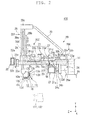
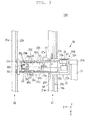
- FIG. 1 is a perspective view illustrating an example of a workpiece conveying device 100 according to a first embodiment.
- FIG. 2 is a side view illustrating an example of the workpiece conveying device 100.
- FIG. 3 is a plan view illustrating an example of the workpiece conveying device 100.
- a part of the workpiece conveying device 100 is illustrated in cross section or omitted.
- the workpiece conveying device 100 includes a workpiece holding section 10 and a moving mechanism 20.
- the workpiece conveying device 100 is mounted on a below-mentioned machine tool for use, and conveys a workpiece W between spindles 111, 112 (indicated by alternate long and short dash lines in FIG. 2 ) provided in the machine tool and a workpiece loading/unloading section (not illustrated).
- the workpiece holding section 10 includes a loader head 11.
- the loader head 11 includes chucks 12, 13 that grip the workpiece W.
- One of the chucks 12, 13 is disposed so as to face the spindle 111 (oriented in the -Z direction), and the other is disposed so as to face the floor face (oriented in the -Y direction).
- the loader head 11 is provided with a rotating mechanism (not illustrated) that exchanges the positions of the two chucks 12, 13.
- the rotating mechanism is rotatable about an axis inclined relative to the Y axis by a predetermined angle (e.g., 45 degrees).
- the rotating mechanism can exchange the positions of the two chucks 12, 13.
- the chucks 12, 13 include base members 12a, 13a, chuck jaws 12b, 13b, pusher plates 12c, 13c, and elastic members 12d, 13d, respectively.
- the base members 12a, 13a support the chuck jaws 12b, 13b and the elastic members 12d, 13d, respectively.
- the plurality of chuck jaws 12b, 13b are arranged at predetermined intervals on the peripheries of the chucks 12, 13, respectively.
- the chuck jaws 12b, 13b can be moved in the radial direction of the chucks 12, 13 to hold the workpiece W.
- a driving source for moving the chuck jaws 12b, 13b is provided, for example, in the loader head 11.
- the pusher plates 12c, 13c press an end face of the workpiece W.
- the pusher plates 12c, 13c are formed in a triple arm shape so as not to interfere with the chuck jaws 12b, 13b, respectively.
- the pusher plates 12c, 13c are supported by the elastic members 12d, 13d, respectively.
- the elastic members 12d, 13d can push out the workpiece W via the pusher plates 12c, 13c.
- the moving mechanism 20 moves the workpiece holding section 10.
- the moving mechanism 20 includes an X moving mechanism 20X, a Z moving mechanism 20Z, and a Y moving mechanism 20Y.
- the X moving mechanism 20X includes a first guide 21, a second guide 22, a movable body 23, and a driving section 24.
- the first guide 21 and the second guide 22 guides the movable body 23.
- the first guide 21 and the second guide 22 are formed longitudinally in the X direction, and are disposed spaced apart from each other in the Z direction.
- the first guide 21 and the second guide 22 are substantially parallel to each other in the X direction.
- the first guide 21 includes a frame 21a, a rack 21b, a rail 21c, and a block 21d.
- the first guide 21 has a higher strength than the second guide 22, to be described below.
- the frame 21a extends in the X direction, and is fixed to a fixing section (not illustrated).
- the frame 21a is formed hollow, for example, but may be formed solid.
- the frame 21a is formed rectangular when viewed in the X direction, for example, but the present invention is not limited thereto, and the frame 21a may have any other shape such as circle and triangle.
- the rack 21b is disposed on a -Z side face of the frame 21a, and is formed linearly in the X direction. On a -Y side face of the rack 21b, a plurality of teeth are formed. The plurality of teeth are arranged at predetermined pitches in the X direction.
- the rail 21c and the block 21d constitute, for example, a linear guide.
- the rail 21c is disposed on an upper face (+Y side face) of the frame 21a, and is formed linearly in the X direction.
- the block 21d is attached to an upper portion of the rail 21c, and is movable along the rail 21c in the X direction.
- the second guide 22 includes a frame 22a and a protruding piece 22b.
- the frame 22a is formed hollow, for example, but may be formed solid.
- the frame 22a is formed rectangular when viewed in the X direction, for example, but the present invention is not limited thereto, and the frame 22a may have any other shape such as circle and triangle.
- the frame 22a is disposed above (+Y side position) the frame 21a of the first guide 21.
- the frame 22a is provided with the protruding piece 22b.
- the protruding piece 22b is disposed on the -Z side face of the frame 22a, and is formed on substantially the entire -Z side face in the X direction.
- the protruding piece 22b protrudes toward the first guide 21 in the -Z direction.
- the movable body 23 is provided so as to extend between the first guide 21 and the second guide 22.
- the movable body 23 includes a first structure 23a, a second structure 23b, and a joint 23c.
- the first structure 23a is connected to an upper face of the block 21d of the first guide 21. Accordingly, the block 21d moves along the rail 21c so that the first structure 23a can move in the X direction integrally with the block 21d. In this manner, the first structure 23a is guided by the first guide 21.
- the +Z side end of the first structure 23a is coupled to the second structure 23b via the joint 23c.
- the first structure 23a includes a driving-section support section 23d protruding in the -Y direction.
- the driving-section support section 23d is formed integrally with the first structure 23a, and supports the driving section 24, to be described later.
- the second structure 23b has a bottom disposed along the XZ plane and walls disposed along the +X side and the -X side.
- Rollers 23e are provided at a +Z side end of the second structure 23b.
- the pair of rollers 23e are provided so as to sandwich the protruding piece 22b therebetween in the Y direction.
- a below-mentioned elevating section 29 rises and falls in the Y direction. With the pair of rollers 23e sandwiching the protruding piece 22b in the Y direction, loads caused by movement of the elevating section 29 can be supported in both of the +Y direction and the -Y direction.
- the rollers 23e are provided so as to roll on the respective upper and lower faces of the protruding piece 22b in the X direction.
- the protruding piece 22b is not limited to a plate-like shape, and may be cylindrical, for example. In the case of the cylindrical protruding piece 22b, a roller having a concave face is brought into contact with the protruding piece 22b. The roller may be disposed on the frame 22a.
- the joint 23c is tubular, or has a tubular coupling member 23f.
- the coupling member 23f is disposed parallel to the X direction.
- the coupling member 23f couples the first structure 23a and the second structure 23b such that the structures can swing about an axis of a central shaft AX. Consequently, the central shaft AX of the coupling member 23f serves as a swing shaft about which the first structure 23a and the second structure 23b swing.
- a swing shaft AX such a shaft will be referred to as a swing shaft AX.
- the swing shaft AX is set parallel to the X direction.
- one of the first structure 23a and the second structure 23b can swing about the axis of the swing shaft AX with respect to the other of the first structure 23a and the second structure 23b.
- the first structure 23a is supported by the +Y side face and the -Z side face of the frame 21a and thus, is restricted from rotating about the axis parallel to the X direction (axis of the swing shaft AX).
- the second structure 23b is disposed such that it can swing about the axis of the swing shaft AX.
- the swing shaft AX is disposed such that a distance to the first guide 21 is smaller than a distance to the second guide 22.
- the -Y side face of the first structure 23a is provided with a stopper 23i.
- the stopper 23i restricts the rotation by locking the second structure 23b such that the second structure 23b does not rotate by a predetermined angle or more, for example, at the time of assembly.
- the driving section 24 includes a driving source 24a, a transmission mechanism 24b, and a pinion 24c.
- the driving source 24a is supported by the driving-section support section 23d of the first structure 23a.
- Examples of the driving source 24a include a motor device.
- the driving source 24a rotates an output shaft (not illustrated) about the Z axis.
- the transmission mechanism 24b is coupled to the above-mentioned output shaft, and transmits rotation caused in the driving source 24a to the pinion 24c.
- the pinion 24c can rotate about the Z axis, and has a plurality of teeth arranged in a peripheral direction. The teeth of the pinion 24c are arranged to engage with the teeth of the rack 21b.
- the rotational force generated in the driving source 24a is transmitted to the pinion 24c via the transmission mechanism 24b to rotate the pinion 24c. Because the rack 21b (frame 21a) side is fixed, the pinion 24c moves in the X direction with respect to the rack 21b integrally with the driving-section support section 23d and the first structure 23a.
- the first structure 23a is connected to the block 21d on the +Y side of the frame 21a and to the rack 21b on the -Z side of the frame 21a, thereby being restricted from rotating about the axis parallel to the X direction.
- the Z moving mechanism 20Z includes guide sections 25, a slider 26, and a driving section 27.
- the guide sections 25 are provided on the +X side wall and the -X side wall of the second structure 23b.
- the guide sections 25 each extend in the Z direction.
- the guide sections 25 guide the slider 26.
- the slider 26 is formed in a rectangular parallelepiped shape.
- the slider 26 has a through hole 26a penetrating the elevating section 29.
- the slider 26 is provided with a rack 26b.
- the rack 26b is formed linearly in the Z direction, and has a plurality of teeth on its -X side face. The plurality of teeth are arranged in the Z direction.
- the driving section 27 includes a driving source 27a and a pinion 27b.
- the driving source 27a is supported by the -X side wall of the second structure 23b.
- Examples of the driving source 27a include a motor device.
- the driving source 27a transmits the rotational force about the Y axis to the pinion 27b via a transmission mechanism (not illustrated).
- the pinion 27b is attached to the second structure 23b so as to be rotatable about the Y axis.
- the pinion 27b has a plurality of teeth arranged in the peripheral direction.
- the teeth of the pinion 27b are arranged to engage with the teeth of the rack 26b.
- the rotational force generated in the driving source 27a is transmitted to the pinion 27b via a transmission mechanism (not illustrated) to rotate the pinion 27b. Since the pinion 27b is attached to the second structure 23b, due to the rotation of the pinion 27b, the rack 26b is driven in the Z direction with respect to the pinion 27b. Thereby,
- the Y moving mechanism 20Y includes guide sections 28, the elevating section 29, and a driving section 30.
- the guide sections 28 guide the elevating section 29.
- the guide sections 28 are formed on the +X side inner wall and the -X side inner wall of the through hole 26a.
- the guide sections 28 each extend parallel to the Y direction.
- the guide sections 28 have grooves formed linearly in the Y direction.
- the elevating section 29 is formed in a bar-shape. Protruding pieces 29a are provided on the +X side face and the -X side face of the elevating section 29. The protruding pieces 29a are formed linearly in the Y direction. The protruding pieces 29a are inserted into the respective grooves of the guide sections 28. Accordingly, the elevating section 29 is guided by the guide sections 28 in the Y direction with the protruding pieces 29a inserted into the grooves of the guide sections 28.
- the elevating section 29 is provided with a rack 29b.
- the rack 29b is formed linearly in the Y direction, and has a plurality of teeth on its +X side face. The plurality of teeth are arranged in the Y direction.
- the workpiece holding section 10 is fixed to the -Y side end of the elevating section 29.
- the driving section 30 includes a driving source 30a, an output shaft 30b, a spline 30c, and a pinion 30d.
- the driving source 30a is supported by the upper face (+Y side face) of the first structure 23a. Since the driving source 30a is supported by the first structure 23a instead of the slider 26, the weight of the slider 26 can be reduced. Note that the driving source 30a may be supported by the slider 26. Examples of the driving source 30a include a motor device.
- the driving source 30a transmits the rotational force about the Z axis to the pinion 30d via the output shaft 30b and the spline 30c.
- a groove extending in the Z direction is formed on an outer periphery of the output shaft 30b.
- a groove is formed on an inner periphery of the spline 30c to engage with the groove on the outer periphery of the output shaft 30b.
- the spline 30c is fixed to the slider 26, and is movable in the Z direction integrally with the slider 26.
- the pinion 30d is fixed to the +Z side end of the spline 30c, and has a plurality of teeth arranged in the peripheral direction.
- the teeth of the pinion 30d are disposed to engage with the teeth of the rack 29b.
- the rotational force generated in the driving source 30a is transmitted to the pinion 30d via the output shaft 30b and the spline 30c to rotate the pinion 30d about the Z axis. Because the pinion 30d is fixed to the slider 26, due to the rotation of the pinion 30d, the rack 29b is driven in the Y direction with respect to the pinion 30d. Thereby, the elevating section 29 moves along the guide sections 28 in the Y direction.
- Protective guide members 31 to 33 accommodate various cables including power feeding cables for the chucks 12, 13. As illustrated in FIG. 2 , one end of the protective guide member 31 is fixed to a fixing section 35 provided at a predetermined position. The other end of the protective guide member 31 is fixed to an attaching section 23g provided at the -Z side end of the first structure 23a. One end of the protective guide member 32 is fixed to an attaching section 23j of the second structure 23b. The other end of the protective guide member 32 is fixed to an attaching section 26c of the slider 26. One end of the protective guide member 33 is fixed to an attaching section 23h provided at the -Z side end of the second structure 23b. The other end of the protective guide member 33 is fixed to an attaching section 29c provided at the +Y side end of the elevating section 29.
- the X moving mechanism 20X moves the movable body 23 in the X direction.
- the slider 26 and the elevating section 29 move in the X direction integrally with the movable body 23. In this case, relative movement between the movable body 23, the slider 26, and the elevating section 29 does not occur.
- the Z moving mechanism 20Z moves the slider 26 in the Z direction.
- the elevating section 29 moves in the Z direction integrally with the slider 26, but the movable body 23 does not move. Accordingly, due to the movement of the slider 26, the elevating section 29 moves in the Z direction with respect to the movable body 23.
- the driving source 30a of the elevating section 29 is supported by the first structure 23a, thereby reducing a load on the driving section 27 during the movement of the slider 26.
- the Y moving mechanism 20Y moves the elevating section 29 in the Y direction.
- the movable body 23 and the slider 26 do not move. Consequently, due to the movement of the elevating section 29, the elevating section 29 moves in the Y direction with respect to both of the movable body 23 and the slider 26.
- the movable body 23 extends between the first guide 21 and the second guide 22.
- the first guide 21 is different from the second guide 22 in height (position in the Y direction) or distance therebetween depending on places
- loads may be exerted on the first guide 21, the second guide 22, and the movable body itself with the movement of the movable body.
- This disadvantageously obstructs smooth movement of the movable body as well as shortens the life of the first guide 21 and the second guide 22.
- the first guide 21 and the second guide 22 can be positioned with high accuracy, bending of the frame 21a, 22a and the like need to be considered, which requires an excessive workload during installation.
- the movable body 23 includes the first structure 23a, the second structure 23b, and the joint 23c, and at the joint 23c, the second structure 23b can swing about the axis of the swing shaft AX with respect to the first structure 23a. For this reason, when the movable body 23 moves in the X direction, at the joint 23c, the second structure 23b swings about the axis of the swing shaft AX so as to follow the first guide 21 and the second guide 22.
- the second structure 23b swings about the axis of the swing shaft AX such that its +Z side end is inclined toward the +Y side.
- the first structure 23a does not swing about the axis of the swing shaft AX. In this case, a load on mainly the first guide 21 (for example, a rail 21c) can be reduced.
- the second structure 23b swings about the axis of the swing shaft AX such that its +Z side end is inclined toward the -Y side.
- the first structure 23a does not swing about the axis of the swing shaft AX.
- a load on mainly the first guide 21 (for example, the rail 21c) can be reduced.
- the actual swinging of the second structure 23b includes a minute swinging that cannot be visually recognized. In FIGS. 4A and 4B , to clarify the swinging of the second structure 23b, the swinging is exaggerated than the actual swinging.
- FIG. 5 shows the example of the case where the +Z side of the second structure 23b is inclined toward the -Y side, the present invention is not limited thereto, and a similar stopper may be provided also in the case where the +Z side of the second structure 23b is inclined toward the +Y side.
- the first structure 23a swings about the axis of the swing shaft AX such that the -Z side end of the first structure 23a is inclined toward the +Y side or the -Y side.
- a load on mainly the second guide 22 (for example, the protruding piece 22b) can be reduced.
- the weight of the movable body 23 can be reduced. Since the first structure 23a and the second structure 23b swing via the joint 23c, loads on the movable body 23, the first guide 21, and the second guide 22 can be reduced. Because the loads on the first guide 21 and the second guide 22 can be reduced by the swinging of the first structure 23a and the second structure 23b, it is not necessary to adjust the positions of the first guide 21 and the second guide 22 with high accuracy.
- the two guides i.e., the first guide 21 and the second guide 22 are used, it is possible to ensure smooth movement of the movable body 23, suppress a decrease in the life of the first guide 21 and the second guide 22, and further, reduce loads on the first guide 21 and the second guide 22 at installation.
- a machine tool including the workpiece conveying device 100 in the first embodiment will be described by way of example.
- the second embodiment uses the same XYZ orthogonal coordinate system as in the first embodiment.
- the rotary axis direction of the spindles 111, 112 is defined as the Z direction
- the direction of defining the cut amount of the workpiece W is defined as the X direction.
- FIGS. 6A and 6B illustrate an example of a machine tool 200 according to the second embodiment.
- the machine tool 200 illustrated in FIGS. 6A and 6B is a parallel biaxial lathe, for example.
- the +Z side of the machine tool 200 is a front face
- the -Z side is a back face.
- the ⁇ X sides of the machine tool 200 are side faces
- the X direction is a lateral direction of the machine tool 200.
- the machine tool 200 includes a body section 110 and a workpiece loading section 120.
- the body section 110 includes spindles 111, 112 and turrets 113, 114.
- the spindles 111, 112 are arranged in the X direction.
- the spindles 111, 112 are rotatably supported by respective bearings (not illustrated).
- the spindles 111, 112 are provided with chuck jaws 111a, 112a, respectively, on their +Z side ends.
- the plurality of chuck jaws 111a, 112a are arranged at predetermined intervals around the rotary axes of the spindles 111, 112, respectively.
- the chuck jaws 111a, 112a can be moved in the radial direction of the spindles 111, 112 to hold the workpiece W.
- the turret 113 is disposed on the +X side of the spindle 111.
- the turret 114 is disposed on the -X side of the spindle 112.
- Each of the turrets 113, 114 is provided with a rotational driving device such as a motor.
- the rotational driving devices enable the turrets 113, 114 to rotate about the axis parallel to the Z direction.
- a plurality of holding sections (not illustrated) for holding a cutting tool are formed on the periphery of each of the turrets 113, 114. All or part of the holding sections hold the cutting tool. Thus, a desired cutting tool is selected by rotating the turrets 113, 114.
- the cutting tools held by the holding sections of the turrets 113, 114 can be exchanged for each holding table.
- the cutting tools include a bit that cuts the workpiece W and rotational tools such as a drill and an end mill.
- the turrets 113, 114 can move in the X direction and the Z direction by means of a driving device (not illustrated). Thereby, the cutting tool can move in the X direction and the Z direction with respect to the workpiece W.
- the workpiece W to be processed using the machine tool 200 is placed on the workpiece loading section 120.
- the workpiece loading section 120 is, for example, a fixing table, but is not limited thereto, and may be a conveyor or a rotary table.
- some machine tools include a workpiece conveying device 130.
- the workpiece conveying device 100 in the first embodiment is used as the workpiece conveying device 130.
- the two guides i.e., the first guide 21 and the second guide 22 stretch over the body section 110 and the workpiece loading section 120 in the X direction such that the workpiece holding section 10 can move between the spindles 111, 112 and the workpiece loading section 120.
- the movable body 23 moves in the X direction, so that the workpiece W can be conveyed between the spindles 111, 112 and the workpiece loading section 120.
- the movable body 23 extends between the first guide 21 and the second guide 22.
- the movable body 23 includes the first structure 23a, the second structure 23b, and the joint 23c, and at the joint 23c, the second structure 23b can swing about the axis of the swing shaft AX with respect to the first structure 23a.
- the workpiece conveying device 130 disposes the workpiece holding section 10 above (+Y side) the workpiece loading section 120. Thereafter, as illustrated in FIG. 6A , the elevating section 29 is moved in the -Y direction with the chuck 12 of the loader head 11 facing the lower side (-Y direction), and the workpiece W is gripped by the chuck jaw 12b.
- the chuck 12 and the chuck 13 are exchanged by a rotating mechanism (not illustrated).
- a rotating mechanism not illustrated
- the chuck 12 and the workpiece W are oriented to the -Z side
- the chuck 13 is oriented to the -Y side.
- the elevating section 29 is moved in the +Y direction to pull up the workpiece W.
- the X moving mechanism 20X moves the movable body 23 in the +X direction, so that the loader head 11 and the workpiece W are disposed above (+Y side) the spindle 111.
- the case where the workpiece W is disposed at the spindle 111 will be described below by way of example. In the case where the workpiece W is disposed at the spindle 112, the loader head 11 and the workpiece W are disposed above the spindle 112.
- the second structure 23b swings about the axis of the swing shaft AX so as to follow the first guide 21 and the second guide 22.
- the first structure 23a does not swing about the axis of the swing shaft AX. In this case, a load on mainly the first guide 21 can be reduced.
- the Y moving mechanism 20Y moves the elevating section 29 in the -Y direction to cause the workpiece W to face the spindle 111.
- the Z moving mechanism 20Z moves the slider 26 in the -Z direction so that the workpiece W is held by the chuck jaw 111a of the spindle 111.
- the loader head 11 is moved in the +Z direction and the +Y direction.
- the workpiece W is processed according to a predetermined processing recipe by using a tool (not illustrated) provided in the turret 114.
- the workpiece conveying device 100 that can suppress a decrease in the life of the first guide 21 and the second guide 22, and reduce a workload of assembly is used as the workpiece conveying device 130, whereby the accuracy of conveying the workpiece W can be stabilized and the machine tool 200 that can be manufactured at low costs can be obtained.
- the workpiece conveying device 100 conveys the workpiece W between the workpiece loading section 120 for loading the workpiece W and the spindles 111, 112, but the present invention is not limited thereto.
- the workpiece conveying device 100 may convey the workpiece W between the spindles 111, 112 and the workpiece unloading section.
- the configuration in which one set of the workpiece holding section 10 and the moving mechanism 20 of the workpiece conveying device 130 is provided has been described by way of example, but the present invention is not limited thereto, and multiple sets of the workpiece holding sections 10 and the moving mechanisms 20 may be provided. In this case, the plurality of moving mechanisms 20 may share the first guide 21 and the second guide 22.
Landscapes
- Engineering & Computer Science (AREA)
- Mechanical Engineering (AREA)
- Robotics (AREA)
- Machine Tool Units (AREA)
- Turning (AREA)
- Feeding Of Workpieces (AREA)
Abstract
Description
- The present invention relates to a workpiece conveying device and a machine tool.
- A lathe that is one of machine tools may include a workpiece conveying device for conveying a workpiece between a spindle that holds the workpiece to be processed and a workpiece loading/unloading section. Such a known workpiece conveying device includes a chuck that holds the workpiece and a movable body that holds the chuck and moves (refer to Japanese Unexamined Patent Publication No.
2004-216504 2004-216504 - When one guide supports the movable body, the movable body overhangs the guide and thus, the movable body is required to have enough stiffness to prevent deformation. For this reason, the movable body becomes heavy, obstructing high-speed movement. Thus, Japanese Unexamined Patent Publication No.
2004-216504 - However, it was recognized that with the structure using two guides, each guide and the movable body may receive a load by the movement of the movable body due to a mounting error between the guides in height or distance, disadvantageously limiting smooth movement of the movable body and shortening the life of the guides. Although the two guides can be positioned with respect to a frame with high accuracy, bending of the frame and the like need to be considered, which requires a large workload during installation of the guides.
- In consideration of the above-mentioned situation, an object of the present invention is to provide a workpiece conveying device and a machine tool that can reduce a weight of a movable body by using two guides, ensure smooth movement of the movable body, suppress a decrease in life of the guides, and reduce a workload during installation of the guides.
- A workpiece conveying device according to the present invention is a workpiece conveying device for conveying a workpiece, the workpiece conveying device including a chuck that holds the workpiece, and a movable body that supports the chuck, and is movable in a first direction along a first guide and a second guide, the guides disposed in parallel spaced apart from each other, wherein the movable body includes a first structure guided by the first guide, a second structure guided by the second guide, and a joint that is provided between the first structure and the second structure, and allows one of the first structure and the second structure to swing with respect to the other about an axis of a swing shaft set parallel to the first direction.
- The first structure may be guided in the first direction by the first guide while being restricted from rotating about the axis parallel to the first direction, and the second structure may be swingable about the axis of the swing shaft with respect to the first structure. The first structure may include a driving section for movement in the first direction. The second guide may include a protruding piece that is formed over a whole length of the second guide and protrudes toward the first guide, and the second structure may include a pair of rollers that sandwich the protruding piece. The swing shaft of the joint may be disposed such that a distance to the first guide is smaller than a distance to the second guide. The first direction may be set along a horizontal plane, the second structure may include a slider that moves in a second direction, the second direction crossing the first direction and set along the horizontal plane, and an elevating section that is supported by the slider and is movable in a third direction vertical to the horizontal plane, and the chuck may be disposed below the elevating section. The first guide may have a higher strength than the second guide. The chuck may include a chuck jaw that can grip the workpiece, and an elastic member that pushes out the workpiece when the gripping by the chuck jaw is released.
- A machine tool according to the present invention includes a workpiece conveying device for conveying a workpiece to a spindle, and uses the above-mentioned workpiece conveying device as the workpiece conveying device.
- According to the present invention, by using the two guides, i.e., the first guide and the second guide, a movable body having a lower stiffness can be used as compared to the case of using one guide, and the weight of the movable body can be reduced. Even in the case where the first guide is different from the second guide in height (vertical position) or distance therebetween, when the movable body moves in the first direction, at the joint, the first structure and the second structure swing about the axis of the swing shaft so as to follow the first guide and the second guide. The swinging of the first structure and the second structure reduces loads on the movable body, the first guide, and the second guide. Because the loads on the first guide and the second guide can be reduced by the swinging of the first structure and the second structure, it is not necessary to position the first guide and the second guide with high accuracy. Thus, even when the two guides, i.e., the first guide and the second guide are used, it is possible to ensure smooth movement of the movable body, suppress a decrease in the life of the guides, and reduce a workload during installation of the guides.
- In the workpiece conveying device in which the first structure is guided in the first direction by the first guide while being restricted from rotating about the axis parallel to the first direction, and the second structure can swing about the axis of the swing shaft with respect to the first structure, the movable body can be stably moved. In the workpiece conveying device in which the first structure includes the driving section for movement in the first direction, the movement in the first direction can be stably performed. In the workpiece conveying device in which the second guide includes the protruding piece that is formed over a whole length of the second guide and protrudes toward the first guide, and the second structure includes the pair of rollers that sandwich the protruding piece, displacement in the direction in which the protruding piece is sandwiched can be prevented. In the workpiece conveying device in which the swing shaft of the joint is disposed such that a distance to the first guide is smaller than a distance to the second guide, the inclination caused when the second structure swings can be reduced. In the workpiece conveying device in which the first direction is set along the horizontal plane, the second structure includes a slider that moves in the second direction, the second direction crossing the first direction and set along the horizontal plane, and the elevating section that is supported by the slider and is movable in a third direction vertical to the horizontal plane, and the chuck is disposed below the elevating section, an increase in loads on the first guide and the second guide in the third direction in which the elevating section moves can be prevented. In the workpiece conveying device in which the first guide has a higher strength than the second guide, the first structure can be stably supported by the first guide even when the first structure is designed to be heavier than the second structure. In this case, a stable configuration can be achieved because the light-weight second structure swings. In the workpiece conveying device in which the chuck includes the chuck jaw adapted to grip the workpiece, and the elastic member that pushes out the workpiece when the gripping by the chuck jaw is released, even when the chuck is inclined by the swinging of the second structure, conveyance of the inclined workpiece can be prevented.
- According to the present invention, by using the workpiece conveying device that can suppress a decrease in the life of the first guide and the second guide, and reduce a workload of assembly, the accuracy of conveying the workpiece can be stabilized to obtain a machine tool that can be manufactured at low costs.
-
-
FIG. 1 is a perspective view illustrating an example of a workpiece conveying device according to a first embodiment; -
FIG. 2 is a side sectional view illustrating an example of the workpiece conveying device according to the first embodiment; -
FIG. 3 is a plan view illustrating an example of the workpiece conveying device according to the first embodiment; -
FIGS. 4A and 4B are side views each illustrating an example of an operation of the workpiece conveying device; -
FIG. 5 is a side view illustrating an example of the workpiece conveying device; and -
FIGS. 6A and 6B are perspective views illustrating an example of a machine tool according to a second embodiment; and -
FIG. 7 is a side view illustrating an example of an operation of the workpiece conveying device according to the second embodiment. - Embodiments of the present invention will be described below with reference to the drawings. However, the present invention is not limited thereto. In the drawings, for convenience of description of the embodiments, components are scaled as appropriate, for example, by partial enlargement or exaggeration. In each of the following figures, directions in the figure are described using an XYZ coordinate system. In the XYZ coordinate system, a plane parallel to the horizontal plane is defined as an XZ plane. A direction parallel to the XZ plane is defined as a Z direction, and a direction orthogonal to the Z direction is defined as an X direction. The direction vertical to the XZ plane is defined as a Y direction. In each of the X direction, the Y direction, and the Z direction, the direction indicated by an arrow in the figure is a + direction, and the opposite direction is a - direction.
-
FIG. 1 is a perspective view illustrating an example of aworkpiece conveying device 100 according to a first embodiment.FIG. 2 is a side view illustrating an example of theworkpiece conveying device 100.FIG. 3 is a plan view illustrating an example of theworkpiece conveying device 100. However, to clarify the configuration of theworkpiece conveying device 100, inFIGS. 1 to 3 , a part of theworkpiece conveying device 100 is illustrated in cross section or omitted. - As illustrated in
FIGS. 1 to 3 , theworkpiece conveying device 100 includes aworkpiece holding section 10 and amoving mechanism 20. Theworkpiece conveying device 100 is mounted on a below-mentioned machine tool for use, and conveys a workpiece W betweenspindles 111, 112 (indicated by alternate long and short dash lines inFIG. 2 ) provided in the machine tool and a workpiece loading/unloading section (not illustrated). - As illustrated in
FIG. 2 , theworkpiece holding section 10 includes aloader head 11. Theloader head 11 includeschucks chucks - The
loader head 11 is provided with a rotating mechanism (not illustrated) that exchanges the positions of the twochucks chucks FIG. 2 , thechucks base members jaws pusher plates elastic members - The
base members chuck jaws elastic members chuck jaws chucks chuck jaws chucks chuck jaws loader head 11. - The
pusher plates pusher plates chuck jaws pusher plates elastic members chuck jaws elastic members pusher plates - The moving
mechanism 20 moves theworkpiece holding section 10. The movingmechanism 20 includes anX moving mechanism 20X, a Z moving mechanism 20Z, and aY moving mechanism 20Y. - The
X moving mechanism 20X includes afirst guide 21, asecond guide 22, amovable body 23, and adriving section 24. - The
first guide 21 and thesecond guide 22 guides themovable body 23. Thefirst guide 21 and thesecond guide 22 are formed longitudinally in the X direction, and are disposed spaced apart from each other in the Z direction. Thefirst guide 21 and thesecond guide 22 are substantially parallel to each other in the X direction. - The
first guide 21 includes aframe 21a, arack 21b, arail 21c, and ablock 21d. Thefirst guide 21 has a higher strength than thesecond guide 22, to be described below. - The
frame 21a extends in the X direction, and is fixed to a fixing section (not illustrated). Theframe 21a is formed hollow, for example, but may be formed solid. Theframe 21a is formed rectangular when viewed in the X direction, for example, but the present invention is not limited thereto, and theframe 21a may have any other shape such as circle and triangle. - The
rack 21b is disposed on a -Z side face of theframe 21a, and is formed linearly in the X direction. On a -Y side face of therack 21b, a plurality of teeth are formed. The plurality of teeth are arranged at predetermined pitches in the X direction. - The
rail 21c and theblock 21d constitute, for example, a linear guide. Therail 21c is disposed on an upper face (+Y side face) of theframe 21a, and is formed linearly in the X direction. Theblock 21d is attached to an upper portion of therail 21c, and is movable along therail 21c in the X direction. - The
second guide 22 includes aframe 22a and aprotruding piece 22b. Similarly to theframe 21a of thefirst guide 21, theframe 22a is formed hollow, for example, but may be formed solid. Theframe 22a is formed rectangular when viewed in the X direction, for example, but the present invention is not limited thereto, and theframe 22a may have any other shape such as circle and triangle. - The
frame 22a is disposed above (+Y side position) theframe 21a of thefirst guide 21. Theframe 22a is provided with the protrudingpiece 22b. The protrudingpiece 22b is disposed on the -Z side face of theframe 22a, and is formed on substantially the entire -Z side face in the X direction. The protrudingpiece 22b protrudes toward thefirst guide 21 in the -Z direction. - The
movable body 23 is provided so as to extend between thefirst guide 21 and thesecond guide 22. Themovable body 23 includes afirst structure 23a, asecond structure 23b, and a joint 23c. - The
first structure 23a is connected to an upper face of theblock 21d of thefirst guide 21. Accordingly, theblock 21d moves along therail 21c so that thefirst structure 23a can move in the X direction integrally with theblock 21d. In this manner, thefirst structure 23a is guided by thefirst guide 21. - The +Z side end of the
first structure 23a is coupled to thesecond structure 23b via the joint 23c. Thefirst structure 23a includes a driving-section support section 23d protruding in the -Y direction. The driving-section support section 23d is formed integrally with thefirst structure 23a, and supports the drivingsection 24, to be described later. - The
second structure 23b has a bottom disposed along the XZ plane and walls disposed along the +X side and the -X side.Rollers 23e are provided at a +Z side end of thesecond structure 23b. The pair ofrollers 23e are provided so as to sandwich the protrudingpiece 22b therebetween in the Y direction. A below-mentioned elevatingsection 29 rises and falls in the Y direction. With the pair ofrollers 23e sandwiching the protrudingpiece 22b in the Y direction, loads caused by movement of the elevatingsection 29 can be supported in both of the +Y direction and the -Y direction. Therollers 23e are provided so as to roll on the respective upper and lower faces of the protrudingpiece 22b in the X direction. In this manner, thesecond structure 23b is guided to thesecond guide 22 via therollers 23e. The protrudingpiece 22b is not limited to a plate-like shape, and may be cylindrical, for example. In the case of the cylindrical protrudingpiece 22b, a roller having a concave face is brought into contact with the protrudingpiece 22b. The roller may be disposed on theframe 22a. - The joint 23c is tubular, or has a
tubular coupling member 23f. Thecoupling member 23f is disposed parallel to the X direction. Thecoupling member 23f couples thefirst structure 23a and thesecond structure 23b such that the structures can swing about an axis of a central shaft AX. Consequently, the central shaft AX of thecoupling member 23f serves as a swing shaft about which thefirst structure 23a and thesecond structure 23b swing. Hereinafter, such a shaft will be referred to as a swing shaft AX. - The swing shaft AX is set parallel to the X direction. In the joint 23c, one of the
first structure 23a and thesecond structure 23b can swing about the axis of the swing shaft AX with respect to the other of thefirst structure 23a and thesecond structure 23b. In this embodiment, as described below, thefirst structure 23a is supported by the +Y side face and the -Z side face of theframe 21a and thus, is restricted from rotating about the axis parallel to the X direction (axis of the swing shaft AX). Thesecond structure 23b is disposed such that it can swing about the axis of the swing shaft AX. In this case, the swing shaft AX is disposed such that a distance to thefirst guide 21 is smaller than a distance to thesecond guide 22. With this configuration, when the +Z side end of thesecond structure 23b is displaced in the Y direction, a change of a swing angle is suppressed, thereby enabling stable movement of themovable body 23. As illustrated inFIG. 2 , the -Y side face of thefirst structure 23a is provided with astopper 23i. Thestopper 23i restricts the rotation by locking thesecond structure 23b such that thesecond structure 23b does not rotate by a predetermined angle or more, for example, at the time of assembly. - The driving
section 24 includes a drivingsource 24a, atransmission mechanism 24b, and apinion 24c. The drivingsource 24a is supported by the driving-section support section 23d of thefirst structure 23a. Examples of the drivingsource 24a include a motor device. The drivingsource 24a rotates an output shaft (not illustrated) about the Z axis. Thetransmission mechanism 24b is coupled to the above-mentioned output shaft, and transmits rotation caused in the drivingsource 24a to thepinion 24c. Thepinion 24c can rotate about the Z axis, and has a plurality of teeth arranged in a peripheral direction. The teeth of thepinion 24c are arranged to engage with the teeth of therack 21b. The rotational force generated in the drivingsource 24a is transmitted to thepinion 24c via thetransmission mechanism 24b to rotate thepinion 24c. Because therack 21b (frame 21a) side is fixed, thepinion 24c moves in the X direction with respect to therack 21b integrally with the driving-section support section 23d and thefirst structure 23a. Thefirst structure 23a is connected to theblock 21d on the +Y side of theframe 21a and to therack 21b on the -Z side of theframe 21a, thereby being restricted from rotating about the axis parallel to the X direction. - The Z moving mechanism 20Z includes
guide sections 25, aslider 26, and adriving section 27. Theguide sections 25 are provided on the +X side wall and the -X side wall of thesecond structure 23b. Theguide sections 25 each extend in the Z direction. Theguide sections 25 guide theslider 26. Theslider 26 is formed in a rectangular parallelepiped shape. Theslider 26 has a throughhole 26a penetrating the elevatingsection 29. Theslider 26 is provided with arack 26b. Therack 26b is formed linearly in the Z direction, and has a plurality of teeth on its -X side face. The plurality of teeth are arranged in the Z direction. - The driving
section 27 includes a drivingsource 27a and apinion 27b. The drivingsource 27a is supported by the -X side wall of thesecond structure 23b. Examples of the drivingsource 27a include a motor device. The drivingsource 27a transmits the rotational force about the Y axis to thepinion 27b via a transmission mechanism (not illustrated). Thepinion 27b is attached to thesecond structure 23b so as to be rotatable about the Y axis. Thepinion 27b has a plurality of teeth arranged in the peripheral direction. The teeth of thepinion 27b are arranged to engage with the teeth of therack 26b. The rotational force generated in the drivingsource 27a is transmitted to thepinion 27b via a transmission mechanism (not illustrated) to rotate thepinion 27b. Since thepinion 27b is attached to thesecond structure 23b, due to the rotation of thepinion 27b, therack 26b is driven in the Z direction with respect to thepinion 27b. Thereby, theslider 26 moves along theguide sections 25 in the Z direction. - The
Y moving mechanism 20Y includesguide sections 28, the elevatingsection 29, and adriving section 30. Theguide sections 28 guide the elevatingsection 29. Theguide sections 28 are formed on the +X side inner wall and the -X side inner wall of the throughhole 26a. Theguide sections 28 each extend parallel to the Y direction. Theguide sections 28 have grooves formed linearly in the Y direction. - The elevating
section 29 is formed in a bar-shape. Protrudingpieces 29a are provided on the +X side face and the -X side face of the elevatingsection 29. The protrudingpieces 29a are formed linearly in the Y direction. The protrudingpieces 29a are inserted into the respective grooves of theguide sections 28. Accordingly, the elevatingsection 29 is guided by theguide sections 28 in the Y direction with the protrudingpieces 29a inserted into the grooves of theguide sections 28. The elevatingsection 29 is provided with arack 29b. Therack 29b is formed linearly in the Y direction, and has a plurality of teeth on its +X side face. The plurality of teeth are arranged in the Y direction. Theworkpiece holding section 10 is fixed to the -Y side end of the elevatingsection 29. - The driving
section 30 includes a drivingsource 30a, anoutput shaft 30b, aspline 30c, and apinion 30d. The drivingsource 30a is supported by the upper face (+Y side face) of thefirst structure 23a. Since the drivingsource 30a is supported by thefirst structure 23a instead of theslider 26, the weight of theslider 26 can be reduced. Note that the drivingsource 30a may be supported by theslider 26. Examples of the drivingsource 30a include a motor device. The drivingsource 30a transmits the rotational force about the Z axis to thepinion 30d via theoutput shaft 30b and thespline 30c. A groove extending in the Z direction is formed on an outer periphery of theoutput shaft 30b. A groove is formed on an inner periphery of thespline 30c to engage with the groove on the outer periphery of theoutput shaft 30b. Thespline 30c is fixed to theslider 26, and is movable in the Z direction integrally with theslider 26. - The
pinion 30d is fixed to the +Z side end of thespline 30c, and has a plurality of teeth arranged in the peripheral direction. The teeth of thepinion 30d are disposed to engage with the teeth of therack 29b. The rotational force generated in the drivingsource 30a is transmitted to thepinion 30d via theoutput shaft 30b and thespline 30c to rotate thepinion 30d about the Z axis. Because thepinion 30d is fixed to theslider 26, due to the rotation of thepinion 30d, therack 29b is driven in the Y direction with respect to thepinion 30d. Thereby, the elevatingsection 29 moves along theguide sections 28 in the Y direction. -
Protective guide members 31 to 33 accommodate various cables including power feeding cables for thechucks FIG. 2 , one end of theprotective guide member 31 is fixed to a fixingsection 35 provided at a predetermined position. The other end of theprotective guide member 31 is fixed to an attachingsection 23g provided at the -Z side end of thefirst structure 23a. One end of theprotective guide member 32 is fixed to an attachingsection 23j of thesecond structure 23b. The other end of theprotective guide member 32 is fixed to an attachingsection 26c of theslider 26. One end of theprotective guide member 33 is fixed to an attachingsection 23h provided at the -Z side end of thesecond structure 23b. The other end of theprotective guide member 33 is fixed to an attachingsection 29c provided at the +Y side end of the elevatingsection 29. - When the
workpiece holding section 10 is moved in the X direction in theworkpiece conveying device 100 thus configured, theX moving mechanism 20X moves themovable body 23 in the X direction. At this time, theslider 26 and the elevatingsection 29 move in the X direction integrally with themovable body 23. In this case, relative movement between themovable body 23, theslider 26, and the elevatingsection 29 does not occur. - When the
workpiece holding section 10 is moved in the Z direction, the Z moving mechanism 20Z moves theslider 26 in the Z direction. At this time, the elevatingsection 29 moves in the Z direction integrally with theslider 26, but themovable body 23 does not move. Accordingly, due to the movement of theslider 26, the elevatingsection 29 moves in the Z direction with respect to themovable body 23. In this embodiment, the drivingsource 30a of the elevatingsection 29 is supported by thefirst structure 23a, thereby reducing a load on the drivingsection 27 during the movement of theslider 26. - When the
workpiece holding section 10 is moved in the Y direction, theY moving mechanism 20Y moves the elevatingsection 29 in the Y direction. At this time, themovable body 23 and theslider 26 do not move. Consequently, due to the movement of the elevatingsection 29, the elevatingsection 29 moves in the Y direction with respect to both of themovable body 23 and theslider 26. - In this embodiment, since the
X moving mechanism 20X includes the two guides, i.e. , thefirst guide 21 and thesecond guide 22, themovable body 23 extends between thefirst guide 21 and thesecond guide 22. For example, in the case where thefirst guide 21 is different from thesecond guide 22 in height (position in the Y direction) or distance therebetween depending on places, in the configuration in which the movable body merely extends between the two guides, loads may be exerted on thefirst guide 21, thesecond guide 22, and the movable body itself with the movement of the movable body. This disadvantageously obstructs smooth movement of the movable body as well as shortens the life of thefirst guide 21 and thesecond guide 22. Although thefirst guide 21 and thesecond guide 22 can be positioned with high accuracy, bending of theframe - On the contrary, in this embodiment, the
movable body 23 includes thefirst structure 23a, thesecond structure 23b, and the joint 23c, and at the joint 23c, thesecond structure 23b can swing about the axis of the swing shaft AX with respect to thefirst structure 23a. For this reason, when themovable body 23 moves in the X direction, at the joint 23c, thesecond structure 23b swings about the axis of the swing shaft AX so as to follow thefirst guide 21 and thesecond guide 22. - For example, when the
second guide 22 is located on the +Y side with respect to thefirst guide 21 as illustrated inFIG. 4A , thesecond structure 23b swings about the axis of the swing shaft AX such that its +Z side end is inclined toward the +Y side. Thefirst structure 23a does not swing about the axis of the swing shaft AX. In this case, a load on mainly the first guide 21 (for example, arail 21c) can be reduced. - For example, when the
second guide 22 is located on the -Y side with respect to thefirst guide 21 as illustrated inFIG. 4B , thesecond structure 23b swings about the axis of the swing shaft AX such that its +Z side end is inclined toward the -Y side. Thefirst structure 23a does not swing about the axis of the swing shaft AX. Also in this case, a load on mainly the first guide 21 (for example, therail 21c) can be reduced. Note that the actual swinging of thesecond structure 23b includes a minute swinging that cannot be visually recognized. InFIGS. 4A and 4B , to clarify the swinging of thesecond structure 23b, the swinging is exaggerated than the actual swinging. - As illustrated in
FIG. 5 , when thesecond structure 23b rotates by a predetermined angle or more, for example, at the time of assembly, thestopper 23i on the -Y side face of thefirst structure 23a locks the -Y side face of thesecond structure 23b. This restricts rotation of thesecond structure 23b. AlthoughFIG. 5 shows the example of the case where the +Z side of thesecond structure 23b is inclined toward the -Y side, the present invention is not limited thereto, and a similar stopper may be provided also in the case where the +Z side of thesecond structure 23b is inclined toward the +Y side. - Although not illustrated, in the configuration in which, at the joint 23c, the
first structure 23a swings about the axis of the swing shaft AX, and thesecond structure 23b does not swing about the axis of the swing shaft AX, thefirst structure 23a swings about the axis of the swing shaft AX such that the -Z side end of thefirst structure 23a is inclined toward the +Y side or the -Y side. In this case, a load on mainly the second guide 22 (for example, the protrudingpiece 22b) can be reduced. - As described above, in this embodiment, by using the two guides, i.e., the
first guide 21 and thesecond guide 22, the weight of themovable body 23 can be reduced. Since thefirst structure 23a and thesecond structure 23b swing via the joint 23c, loads on themovable body 23, thefirst guide 21, and thesecond guide 22 can be reduced. Because the loads on thefirst guide 21 and thesecond guide 22 can be reduced by the swinging of thefirst structure 23a and thesecond structure 23b, it is not necessary to adjust the positions of thefirst guide 21 and thesecond guide 22 with high accuracy. Thus, even when the two guides, i.e., thefirst guide 21 and thesecond guide 22 are used, it is possible to ensure smooth movement of themovable body 23, suppress a decrease in the life of thefirst guide 21 and thesecond guide 22, and further, reduce loads on thefirst guide 21 and thesecond guide 22 at installation. - Next, a second embodiment will be described. In the second embodiment, a machine tool including the
workpiece conveying device 100 in the first embodiment will be described by way of example. The second embodiment uses the same XYZ orthogonal coordinate system as in the first embodiment. However, in the second embodiment, the rotary axis direction of thespindles -
FIGS. 6A and 6B illustrate an example of amachine tool 200 according to the second embodiment. Themachine tool 200 illustrated inFIGS. 6A and 6B is a parallel biaxial lathe, for example. InFIGS. 6A and 6B , the +Z side of themachine tool 200 is a front face, and the -Z side is a back face. The ±X sides of themachine tool 200 are side faces, and the X direction is a lateral direction of themachine tool 200. - The
machine tool 200 includes abody section 110 and aworkpiece loading section 120. - The
body section 110 includesspindles turrets spindles spindles spindles chuck jaws chuck jaws spindles chuck jaws spindles - The
turret 113 is disposed on the +X side of thespindle 111. Theturret 114 is disposed on the -X side of thespindle 112. Each of theturrets turrets turrets turrets turrets turrets - The workpiece W to be processed using the
machine tool 200 is placed on theworkpiece loading section 120. Theworkpiece loading section 120 is, for example, a fixing table, but is not limited thereto, and may be a conveyor or a rotary table. - Like the
machine tool 200 illustrated inFIGS. 6A and 6B , some machine tools include aworkpiece conveying device 130. In this case, theworkpiece conveying device 100 in the first embodiment is used as theworkpiece conveying device 130. In theworkpiece conveying device 130, the two guides, i.e., thefirst guide 21 and thesecond guide 22 stretch over thebody section 110 and theworkpiece loading section 120 in the X direction such that theworkpiece holding section 10 can move between thespindles workpiece loading section 120. Thus, in theworkpiece conveying device 130, themovable body 23 moves in the X direction, so that the workpiece W can be conveyed between thespindles workpiece loading section 120. - The
movable body 23 extends between thefirst guide 21 and thesecond guide 22. Themovable body 23 includes thefirst structure 23a, thesecond structure 23b, and the joint 23c, and at the joint 23c, thesecond structure 23b can swing about the axis of the swing shaft AX with respect to thefirst structure 23a. - Next, the operation of the
machine tool 200 thus configured will be described. - First, the
workpiece conveying device 130 disposes theworkpiece holding section 10 above (+Y side) theworkpiece loading section 120. Thereafter, as illustrated inFIG. 6A , the elevatingsection 29 is moved in the -Y direction with thechuck 12 of theloader head 11 facing the lower side (-Y direction), and the workpiece W is gripped by thechuck jaw 12b. - Thereafter, the
chuck 12 and thechuck 13 are exchanged by a rotating mechanism (not illustrated). As a result, thechuck 12 and the workpiece W are oriented to the -Z side, and thechuck 13 is oriented to the -Y side. After thechuck 12 is oriented to the -Z side, the elevatingsection 29 is moved in the +Y direction to pull up the workpiece W. - Next, the
X moving mechanism 20X moves themovable body 23 in the +X direction, so that theloader head 11 and the workpiece W are disposed above (+Y side) thespindle 111. The case where the workpiece W is disposed at thespindle 111 will be described below by way of example. In the case where the workpiece W is disposed at thespindle 112, theloader head 11 and the workpiece W are disposed above thespindle 112. - When the
movable body 23 moves in the X direction, similarly to the first embodiment, at the joint 23c, thesecond structure 23b swings about the axis of the swing shaft AX so as to follow thefirst guide 21 and thesecond guide 22. At this time, thefirst structure 23a does not swing about the axis of the swing shaft AX. In this case, a load on mainly thefirst guide 21 can be reduced. - Next, the
Y moving mechanism 20Y moves the elevatingsection 29 in the -Y direction to cause the workpiece W to face thespindle 111. Then, the Z moving mechanism 20Z moves theslider 26 in the -Z direction so that the workpiece W is held by thechuck jaw 111a of thespindle 111. Thereafter, theloader head 11 is moved in the +Z direction and the +Y direction. Then, the workpiece W is processed according to a predetermined processing recipe by using a tool (not illustrated) provided in theturret 114. - When the
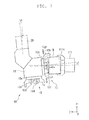
second structure 23b swings by an angle θ with the movement of themovable body 23 in the X direction, as illustrated inFIG. 7 , the elevatingsection 29 swings, and theloader head 11 fixed to the -Y side end of the elevatingsection 29 is inclined with the angle θ. In this case, the orientation of the workpiece W held by thechuck 12 is shifted from thespindle 111 by the angle θ. - On the contrary, in this embodiment, when the gripping of the workpiece W by the
chuck jaw 12b is released, the workpiece W is pushed out toward the -Z side with theelastic member 12d and thepusher plate 12c. At this time, the workpiece W is pushed to the -Z side with respect to thespindle 111, and the -Z side end face of the workpiece W comes into contact with the holding face (parallel to the XY plane) of thespindle 111. Accordingly, the orientation of the workpiece W is corrected such that the end face of the workpiece W becomes parallel to the XY plane. - As described above, according to the second embodiment, the
workpiece conveying device 100 that can suppress a decrease in the life of thefirst guide 21 and thesecond guide 22, and reduce a workload of assembly is used as theworkpiece conveying device 130, whereby the accuracy of conveying the workpiece W can be stabilized and themachine tool 200 that can be manufactured at low costs can be obtained. - The embodiments have been described above, but the present invention is not limited to the above description, and various changes can be made within the scope not deviating from the gist of the present invention.
- For example, in the above embodiments, the
workpiece conveying device 100 conveys the workpiece W between theworkpiece loading section 120 for loading the workpiece W and thespindles workpiece conveying device 100 may convey the workpiece W between thespindles - In the second embodiment, the configuration in which one set of the
workpiece holding section 10 and the movingmechanism 20 of theworkpiece conveying device 130 is provided has been described by way of example, but the present invention is not limited thereto, and multiple sets of theworkpiece holding sections 10 and the movingmechanisms 20 may be provided. In this case, the plurality of movingmechanisms 20 may share thefirst guide 21 and thesecond guide 22.
Claims (9)
- A workpiece conveying device (100, 130) for conveying a workpiece (W), the device comprising:a chuck (12, 13) configured to hold the workpiece (W); anda movable body (23) configured to support the chuck (12, 13), and being movable in a first direction along a first guide (21) and a second guide (22), the guides (21, 22) disposed in parallel spaced apart from each other,wherein the movable body (23) includes a first structure (23a) guided by the first guide (21), a second structure (23b) guided by the second guide (22), and a joint (23c) that is provided between the first structure (23a) and the second structure (23b) and is configured to allow one of the first structure (23a) and the second structure (23b) to swing with respect to the other about an axis of a swing shaft (AX) set parallel to the first direction.
- The workpiece conveying device (100, 130) according to claim 1, wherein
the first structure (23a) is guided in the first direction by the first guide (21) while being restricted from rotating about an axis parallel to the first direction, and
the second structure (23b) is swingable about the axis of the swing shaft (AX) with respect to the first structure (23a). - The workpiece conveying device (100, 130) according to claim 2, wherein
the first structure (23a) includes a driving section (24) for movement in the first direction. - The workpiece conveying device (100, 130) according to claim 2 or claim 3, wherein
the second guide (22) includes a protruding piece (22b) that is formed over a whole length of the second guide (22) and protrudes toward the first guide (21), and
the second structure (23b) includes a pair of rollers (23e) that sandwich the protruding piece (22b). - The workpiece conveying device according to any one of claim 2 to claim 4, wherein
the swing shaft (AX) of the joint (23c) is disposed such that a distance to the first guide (21) is smaller than a distance to the second guide (22). - The workpiece conveying device (100, 130) according to any one of claim 1 to claim 5, wherein
the first direction is set along a horizontal plane,
the second structure (23b) includes a slider (26) configured to move in a second direction, the second direction crossing the first direction and set along the horizontal plane, and an elevating section (29) that is supported by the slider (26) and is movable in a third direction vertical to the horizontal plane, and
the chuck (12, 13) is disposed below the elevating section (29). - The workpiece conveying device (100, 130) according to claim 6, wherein the first guide (21) has a higher strength than the second guide (22).
- The workpiece conveying device (100, 130) according to any one of claim 1 to claim 7, wherein
the chuck (12, 13) includes a chuck jaw (12b, 13b) adapted to grip the workpiece (W), and an elastic member (12d, 13d) configured to push out the workpiece (W) when the gripping by the chuck jaw (12b, 13b) is released. - A machine tool (200) comprising:a workpiece conveying device (130) for conveying a workpiece (W) to a spindle (111, 112), the workpiece conveying device (130) being the workpiece conveying device (100, 130) according to any one of claim 1 to claim 8.
Applications Claiming Priority (1)
| Application Number | Priority Date | Filing Date | Title |
|---|---|---|---|
| JP2014162265A JP2016036880A (en) | 2014-08-08 | 2014-08-08 | Work carrying device and machine tool |
Publications (2)
| Publication Number | Publication Date |
|---|---|
| EP2982474A2 true EP2982474A2 (en) | 2016-02-10 |
| EP2982474A3 EP2982474A3 (en) | 2016-03-02 |
Family
ID=53836415
Family Applications (1)
| Application Number | Title | Priority Date | Filing Date |
|---|---|---|---|
| EP15179630.7A Withdrawn EP2982474A3 (en) | 2014-08-08 | 2015-08-04 | Workpiece conveying device and machine tool |
Country Status (5)
| Country | Link |
|---|---|
| US (1) | US9469005B2 (en) |
| EP (1) | EP2982474A3 (en) |
| JP (1) | JP2016036880A (en) |
| KR (1) | KR101869504B1 (en) |
| CN (1) | CN106180762B (en) |
Cited By (2)
| Publication number | Priority date | Publication date | Assignee | Title |
|---|---|---|---|---|
| EP3441204A1 (en) * | 2017-06-27 | 2019-02-13 | Nakamura-Tome Precision Industry Co., Ltd | Loading device and method tool using the same |
| CN120735081A (en) * | 2025-09-08 | 2025-10-03 | 上海蜘蛛侠机器人有限公司 | A connecting rod driven mechanical gripper |
Families Citing this family (3)
| Publication number | Priority date | Publication date | Assignee | Title |
|---|---|---|---|---|
| EP3718659B1 (en) * | 2019-04-05 | 2022-11-23 | Horstkemper Maschinenbau GmbH | Automation device |
| DE102020102787B3 (en) * | 2020-02-04 | 2021-05-12 | Gressel Ag | Clamping device and method for clamping a workpiece between two clamping devices |
| US12258225B2 (en) | 2020-04-07 | 2025-03-25 | Kuka Systems North America Llc | System and method for automated assembly of components |
Citations (2)
| Publication number | Priority date | Publication date | Assignee | Title |
|---|---|---|---|---|
| JPH0228053A (en) * | 1988-07-18 | 1990-01-30 | Toshiba Corp | Carrier vehicle |
| JP2004216504A (en) | 2003-01-15 | 2004-08-05 | Murata Mach Ltd | Loader control device |
Family Cites Families (19)
| Publication number | Priority date | Publication date | Assignee | Title |
|---|---|---|---|---|
| US3255893A (en) * | 1963-07-10 | 1966-06-14 | Gen Mills Inc | Manipulator boom system |
| EP0076231A3 (en) * | 1981-09-24 | 1984-04-25 | Franz Schäfer | Method and apparatus for the serial treatment and/or the assembly of workpieces |
| FR2522294A1 (en) * | 1982-02-26 | 1983-09-02 | Manurhin Automatic Sa | DEVICE FOR LOADING AND UNLOADING PARTS FOR A MACHINE TOOL SUCH AS A TURNING MACHINE |
| US4637738A (en) * | 1985-07-31 | 1987-01-20 | Vincent Barkley | Alignment compensator for linear bearings |
| JPH03196979A (en) * | 1989-12-26 | 1991-08-28 | Takenaka Komuten Co Ltd | Three shaft mobile device |
| JPH07102509B2 (en) * | 1991-11-18 | 1995-11-08 | ジューキ株式会社 | Head drive mechanism |
| JP3344900B2 (en) * | 1996-09-19 | 2002-11-18 | 松下電器産業株式会社 | Cartesian robot |
| JP3674338B2 (en) * | 1998-10-09 | 2005-07-20 | 日本精工株式会社 | Linear actuator |
| DE10158194A1 (en) * | 2001-11-28 | 2003-06-18 | Mueller Weingarten Maschf | Molding transporting device has first longitudinal carriage on each rail belonging to specific holding device or half of it |
| JP3913556B2 (en) * | 2002-01-22 | 2007-05-09 | 株式会社森精機製作所 | Machine tool workpiece transfer device |
| JP4341540B2 (en) * | 2004-12-07 | 2009-10-07 | 日本精工株式会社 | 3-axis drive |
| EP1952939A1 (en) * | 2007-01-30 | 2008-08-06 | Fritz Studer AG | Workpiece operation device |
| JP4809389B2 (en) * | 2008-04-14 | 2011-11-09 | 村田機械株式会社 | Parallel mechanism |
| JP5385675B2 (en) * | 2009-05-08 | 2014-01-08 | 株式会社森精機製作所 | Machine tools for turning |
| CN103328165B (en) * | 2009-12-21 | 2015-10-21 | 威斯托机械制造及操作技术有限公司 | Manipulation device |
| JP5054830B2 (en) * | 2011-02-04 | 2012-10-24 | 住友化学株式会社 | Honeycomb structure transport device and honeycomb structure sealing method |
| JP5605514B2 (en) * | 2011-08-26 | 2014-10-15 | 村田機械株式会社 | Loader with workpiece tilt detection function |
| CN202701895U (en) * | 2012-06-11 | 2013-01-30 | 卓越(苏州)自动化设备有限公司 | Swing conveyer |
| EP2868434A1 (en) * | 2013-10-30 | 2015-05-06 | Barload Machine Co.,Ltd. | Front door-type automatic material-taking device |
-
2014
- 2014-08-08 JP JP2014162265A patent/JP2016036880A/en active Pending
-
2015
- 2015-07-03 CN CN201510387237.4A patent/CN106180762B/en active Active
- 2015-07-14 US US14/798,612 patent/US9469005B2/en active Active
- 2015-07-31 KR KR1020150108909A patent/KR101869504B1/en not_active Expired - Fee Related
- 2015-08-04 EP EP15179630.7A patent/EP2982474A3/en not_active Withdrawn
Patent Citations (2)
| Publication number | Priority date | Publication date | Assignee | Title |
|---|---|---|---|---|
| JPH0228053A (en) * | 1988-07-18 | 1990-01-30 | Toshiba Corp | Carrier vehicle |
| JP2004216504A (en) | 2003-01-15 | 2004-08-05 | Murata Mach Ltd | Loader control device |
Cited By (2)
| Publication number | Priority date | Publication date | Assignee | Title |
|---|---|---|---|---|
| EP3441204A1 (en) * | 2017-06-27 | 2019-02-13 | Nakamura-Tome Precision Industry Co., Ltd | Loading device and method tool using the same |
| CN120735081A (en) * | 2025-09-08 | 2025-10-03 | 上海蜘蛛侠机器人有限公司 | A connecting rod driven mechanical gripper |
Also Published As
| Publication number | Publication date |
|---|---|
| US20160039062A1 (en) | 2016-02-11 |
| CN106180762A (en) | 2016-12-07 |
| EP2982474A3 (en) | 2016-03-02 |
| KR20160018376A (en) | 2016-02-17 |
| CN106180762B (en) | 2019-03-22 |
| KR101869504B1 (en) | 2018-06-20 |
| JP2016036880A (en) | 2016-03-22 |
| US9469005B2 (en) | 2016-10-18 |
Similar Documents
| Publication | Publication Date | Title |
|---|---|---|
| EP2985114A2 (en) | Workpiece conveying device and machine tool | |
| US9469005B2 (en) | Workpiece conveyor and machine tool | |
| JP6332466B2 (en) | Machine tool system and work transfer method | |
| US10576642B2 (en) | Multi-jointed robot arm | |
| KR102319343B1 (en) | Apparatus for carrying pallet | |
| CN113165128B (en) | Work support device, unloading device, loading device, and long work processing device | |
| JP2008143674A (en) | Workpiece reversing device | |
| WO2019039592A1 (en) | Bending machine | |
| US20210387354A1 (en) | Automatic workpiece carrying machine | |
| US10391639B2 (en) | Transfer tool and robot | |
| CN102481671A (en) | Pallet feed mechanism for a machine tool | |
| WO2015002621A1 (en) | A processing line which can realize processes like drilling, milling and cutting | |
| US9844850B2 (en) | Machine tool | |
| JP5125129B2 (en) | Work supply / discharge device | |
| KR20160070480A (en) | Apparatus for transferring a pallet | |
| JP6634088B2 (en) | Articulated robot arm | |
| JP4343514B2 (en) | Loading device | |
| CN208628512U (en) | Chamfer machining machine | |
| JP2016175154A (en) | Loader device and manufacturing method of the same | |
| JP2015174193A (en) | Loader device and machine tool | |
| JP2017013179A (en) | Processor | |
| JP2023101196A (en) | CHUCK DEVICE, MACHINE TOOL, AND MACHINE TOOL SYSTEM | |
| KR200394222Y1 (en) | Tranfer Equipment for Machine Tool | |
| KR100658051B1 (en) | Machine tool feeders | |
| JP2012040678A (en) | Workpiece conveying apparatus |
Legal Events
| Date | Code | Title | Description |
|---|---|---|---|
| PUAL | Search report despatched |
Free format text: ORIGINAL CODE: 0009013 |
|
| PUAI | Public reference made under article 153(3) epc to a published international application that has entered the european phase |
Free format text: ORIGINAL CODE: 0009012 |
|
| AK | Designated contracting states |
Kind code of ref document: A2 Designated state(s): AL AT BE BG CH CY CZ DE DK EE ES FI FR GB GR HR HU IE IS IT LI LT LU LV MC MK MT NL NO PL PT RO RS SE SI SK SM TR |
|
| AX | Request for extension of the european patent |
Extension state: BA ME |
|
| AK | Designated contracting states |
Kind code of ref document: A3 Designated state(s): AL AT BE BG CH CY CZ DE DK EE ES FI FR GB GR HR HU IE IS IT LI LT LU LV MC MK MT NL NO PL PT RO RS SE SI SK SM TR |
|
| AX | Request for extension of the european patent |
Extension state: BA ME |
|
| RIC1 | Information provided on ipc code assigned before grant |
Ipc: B25J 15/00 20060101ALI20160122BHEP Ipc: B23Q 1/62 20060101ALI20160122BHEP Ipc: B23Q 7/04 20060101AFI20160122BHEP |
|
| 17P | Request for examination filed |
Effective date: 20160816 |
|
| RBV | Designated contracting states (corrected) |
Designated state(s): AL AT BE BG CH CY CZ DE DK EE ES FI FR GB GR HR HU IE IS IT LI LT LU LV MC MK MT NL NO PL PT RO RS SE SI SK SM TR |
|
| RIC1 | Information provided on ipc code assigned before grant |
Ipc: B23B 13/04 20060101ALN20170920BHEP Ipc: B25J 9/02 20060101ALI20170920BHEP Ipc: B25J 5/04 20060101ALI20170920BHEP Ipc: B25J 15/00 20060101ALI20170920BHEP Ipc: B23Q 7/04 20060101AFI20170920BHEP Ipc: B23B 13/02 20060101ALN20170920BHEP Ipc: B23Q 1/62 20060101ALI20170920BHEP |
|
| GRAP | Despatch of communication of intention to grant a patent |
Free format text: ORIGINAL CODE: EPIDOSNIGR1 |
|
| INTG | Intention to grant announced |
Effective date: 20171031 |
|
| STAA | Information on the status of an ep patent application or granted ep patent |
Free format text: STATUS: THE APPLICATION IS DEEMED TO BE WITHDRAWN |
|
| 18D | Application deemed to be withdrawn |
Effective date: 20180313 |