EP2980822A1 - Appareil de commutation de protection et culasse magnétique - Google Patents
Appareil de commutation de protection et culasse magnétique Download PDFInfo
- Publication number
- EP2980822A1 EP2980822A1 EP15167305.0A EP15167305A EP2980822A1 EP 2980822 A1 EP2980822 A1 EP 2980822A1 EP 15167305 A EP15167305 A EP 15167305A EP 2980822 A1 EP2980822 A1 EP 2980822A1
- Authority
- EP
- European Patent Office
- Prior art keywords
- region
- contact
- magnetic yoke
- switching device
- fixed contact
- Prior art date
- Legal status (The legal status is an assumption and is not a legal conclusion. Google has not performed a legal analysis and makes no representation as to the accuracy of the status listed.)
- Granted
Links
Images


Classifications
-
- H—ELECTRICITY
- H01—ELECTRIC ELEMENTS
- H01H—ELECTRIC SWITCHES; RELAYS; SELECTORS; EMERGENCY PROTECTIVE DEVICES
- H01H9/00—Details of switching devices, not covered by groups H01H1/00 - H01H7/00
- H01H9/30—Means for extinguishing or preventing arc between current-carrying parts
-
- H—ELECTRICITY
- H01—ELECTRIC ELEMENTS
- H01H—ELECTRIC SWITCHES; RELAYS; SELECTORS; EMERGENCY PROTECTIVE DEVICES
- H01H71/00—Details of the protective switches or relays covered by groups H01H73/00 - H01H83/00
- H01H71/10—Operating or release mechanisms
- H01H71/12—Automatic release mechanisms with or without manual release
- H01H71/24—Electromagnetic mechanisms
-
- H—ELECTRICITY
- H01—ELECTRIC ELEMENTS
- H01H—ELECTRIC SWITCHES; RELAYS; SELECTORS; EMERGENCY PROTECTIVE DEVICES
- H01H9/00—Details of switching devices, not covered by groups H01H1/00 - H01H7/00
- H01H9/30—Means for extinguishing or preventing arc between current-carrying parts
- H01H9/34—Stationary parts for restricting or subdividing the arc, e.g. barrier plate
- H01H9/36—Metal parts
-
- H—ELECTRICITY
- H01—ELECTRIC ELEMENTS
- H01H—ELECTRIC SWITCHES; RELAYS; SELECTORS; EMERGENCY PROTECTIVE DEVICES
- H01H9/00—Details of switching devices, not covered by groups H01H1/00 - H01H7/00
- H01H9/30—Means for extinguishing or preventing arc between current-carrying parts
- H01H9/44—Means for extinguishing or preventing arc between current-carrying parts using blow-out magnet
- H01H9/446—Means for extinguishing or preventing arc between current-carrying parts using blow-out magnet using magnetisable elements associated with the contacts
-
- H—ELECTRICITY
- H01—ELECTRIC ELEMENTS
- H01H—ELECTRIC SWITCHES; RELAYS; SELECTORS; EMERGENCY PROTECTIVE DEVICES
- H01H9/00—Details of switching devices, not covered by groups H01H1/00 - H01H7/00
- H01H9/30—Means for extinguishing or preventing arc between current-carrying parts
- H01H9/46—Means for extinguishing or preventing arc between current-carrying parts using arcing horns
Definitions
- the invention relates to a protective switching device, in particular a circuit breaker, which has an input terminal and an output terminal, which are designed for contacting with an electrical line.
- the protective switching device has a switching contact, which has a stationary fixed contact and a movably arranged movable contact, which are designed such that forms an arc between the moving contact and the fixed contact when opening the current-carrying switching contact.
- the protective switching device has a short-circuit release system with a coil and a relative thereto movably mounted release means, which is designed to act in the case of triggering on the moving contact to cause an opening of the switching contact.
- the invention further relates to a magnetic yoke, which is arranged adjacent to the coil of the short-circuit release system and serves to reinforce the magnetic effect of the coil on the triggering means in the event of triggering.
- Circuit breakers are designed especially for high currents.
- a circuit breaker (so-called LS switch) is an overcurrent protection device used in electrical installations and is used in particular in the field of low-voltage networks.
- Circuit-breakers and miniature circuit-breakers guarantee a safe shutdown in the event of a short circuit and protect consumers and electrical equipment from overload, for example, from damage to the cables due to excessive heating due to excessive electrical current.
- Circuit breakers and circuit breakers are used in particular as switching and safety elements in electrical energy supply networks and serve the monitoring and protection of an electrical circuit.
- the protective switching device is electrically connected via two terminals with an electrical line of the circuit to be monitored in order to interrupt the electrical current in the respective line when needed.
- the protective switching device in this case has a switching contact with a stationary fixed contact and a movable relative to moving contact.
- the moving contact is actuated via a switching mechanism of the protective switching device, so that the switching contact can be opened and closed. In this way, when a predefined state, for example a short circuit or an electrical overload, occurs, the switching contact is opened in order to disconnect the monitored circuit from the electrical line network.
- Such protective switching devices are known in the field of low-voltage technology as DIN rail mounted devices.
- a so-called fixed contact piece is arranged on the fixed contact in an electrically conductive manner, which cooperates with a moving contact piece arranged in an electrically conductive manner on the moving contact. If the switching contact is opened at a time when an electric current flows via the switching contact, then an arc is formed when the switching contact between the fixed contact piece and the moving contact piece is removed therefrom.
- conventional protective switching devices have a so-called quenching chamber with a multiplicity of splitter plates arranged next to one another and spaced apart from one another. If the arc is driven into the quenching chamber, it divides when hitting the quenching plates into several partial arcs, which then burn in series between the individual quenching plates. The multiple, electrically sequentially connected in succession partial arcs result in total to a higher arc voltage, which leads to a faster extinction of the arc as a result.
- a standing between the fixed contact piece and the BewegCount Swiss arc leads to a so-called contact erosion, i. for a removal of material on the fixed contact piece as well as on the moving contact piece.
- contact erosion leads to increased electrical resistance.
- the contact erosion leads to contamination of the contact pieces with microparticles, which in turn leads to a higher tendency to weld of fixed contact piece and moving contact piece.
- a contact erosion leads to damage of the protective switching device and is therefore to be avoided as much as possible. Therefore, the arc should be driven as quickly as possible away from the lying between the fixed contact and moving contact contact area in the quenching chamber and deleted.
- the protective switching device which is designed in particular as a circuit breaker, has an input terminal and an output terminal, which are designed for contacting the protective switching device with an electrical line. Furthermore, the protective switching device has a switching contact, which in turn has a stationary fixed contact and a movable relative to movable contact, which are designed such that forms an arc between the moving contact and the fixed contact when opening the current-carrying switching contact. Furthermore, the protective switching device on a short-circuit release system, which in turn has a coil and a relative thereto movably mounted release means and is adapted to act in the event of triggering on the moving contact to cause an opening of the switch contact.
- the short-circuit release system on a magnetic yoke which is integrally formed and has a coupling region. Furthermore, the fixed contact is formed by a fixed contact region of the magnetic yoke, which is integrally connected at its first end to the coupling region, and the second end is formed as a free end. Further, the magnetic yoke on a quenching chamber region, which is integrally connected to the coupling region and forms a bypass current path, which in the event of an arc due to an opening of the switching contact after a commutation of the arc is energized from the fixed contact region to the quenching chamber region.
- the protective switching device has a switching contact, consisting of a fixed contact and a movable relative to movable contact on.
- a separate fixed contact piece may be electrically conductively attached to the fixed contact, which cooperates with a moving contact arranged on the moving contact moving contact piece.
- the moving contact can be actuated via a switching mechanism of the protective switching device, the fixed contact is formed as part of the magnetic yoke of the short-circuit release system of the protective switching device, the so-called fixed contact region of the magnetic yoke.
- the action of the triggering means on the moving contact can be effected directly, but also indirectly - for example, by an action of the triggering means on the switching mechanism, which then in turn causes actuation of the moving contact and thus opening of the switching contact. Both possibilities, both indirect and direct action on the moving contact, can be combined.
- the design of the second end of the fixed contact area as a free end causes the fixed contact, although stationary, but not rigidly arranged in the housing of the protective device.
- the design of the second end of the fixed contact area as free end to the fact that in the case of a short circuit, the direct current flow is interrupted after the commutation of the arc to the quenching chamber area.
- the load duration acting on the fixed contact region due to the high short-circuit current can thereby be significantly reduced, so that damage due to high temperatures due to the short-circuit current is avoided.
- the magnetic yoke is integrally formed and therefore - compared to multi-part designs - relatively inexpensive to produce.
- the coupling region serves, for example, the coupling of the magnetic yoke to the coil of the short-circuit release system.
- This coupling can be both electrical, but also magnetic nature.
- a mechanical coupling with a housing of the protective switching device can be realized.
- the coupling region has an opening for the implementation of the triggering means. Since the magnetic yoke - and in particular the coupling region - is at least partially arranged between the short-circuit release system and the moving contact, the opening formed in the coupling region of the magnetic yoke represents a simple, space-saving and cost-effective means for acting on the moving contact with the aid of the triggering means Opening the switch contact to effect.
- the coupling region is shaped such that a magnetic core is formed, which is at least partially received in the coil in the mounted state.
- the magnetic core serves to significantly enhance the magnetic effect of the trip coil. This effect can be improved, ie increased, when the magnetic core is at least partially immersed in the coil.
- the coupling region of the magnetic coupling of the magnetic yoke is used with the coil of Kur gleichauslettessystems.
- the coupling region is designed for fastening a magnetic core, which is accommodated in the assembled state at least partially in the coil.
- the magnetic core can also be mounted as a separate component on the coupling region of the magnetic yoke. This has the advantage that the magnetic core can be made more massive, which increases its magnetic effect.
- a suitable material can be selected for this purpose without the design of the magnetic yoke having to be taken into account. This leads to significantly higher degrees of freedom with regard to the structural design of the protective switching device, which is particularly advantageous in high-end devices.
- the magnetic core can be connected to the coupling region by means of welding or riveting.
- Welding or riveting represent simple and cost-effective method for producing a connection of the magnetic core with the coupling region of the magnetic yoke.
- the free second end of the fixed contact region is designed as a contact horn.
- the contact horn which is oriented towards the quenching chamber area at the free end, the arc produced during the opening of the energized switching contact is pulled away from the switching contact in the direction of the quenching chamber or the prechamber region arranged in front of the quenching chamber.
- the arc commutes from the fixed contact region to the quenching chamber region of the magnetic yoke. From this point on, the electric current thus no longer flows through the fixed contact area, but via the bypass current path which is now energized. In this way, a re-ignition of the arc in the contact area as well as excessive heating - and thus a possible damage to the fixed contact area - effectively avoided.
- an electrical connection region is formed by a connection region of the coupling region with the extinguishing chamber region for contacting the coil.
- an electrical connection region for contacting the coil is formed on the coupling region, which is arranged opposite a connection region of the coupling region with the quenching chamber region.
- connection region of the coil at a connection region of the coupling region with the quenching chamber region, or opposite this connection region represent possible alternatives for electrically contacting the coil with the magnetic yoke.
- the advantage of the respective alternative is the arrangement of the remaining components of the protective switching device , Especially in confined spaces, as well as the requirements for the most ergonomic mountability of the protection device dependent.
- the magnetic yoke is produced as a sheet metal bent part.
- the design as a bent sheet metal part represents an extremely cost-effective way of producing the magnetic yoke.
- the magnetic yoke according to the invention for a short-circuit release system of a protective switching device, in particular a circuit breaker, is integrally formed and has a coupling region. Furthermore, the magnetic yoke on a fixed contact region, which forms a stationary part of a switching contact of the protective switching device, is integrally connected at its first end to the coupling region, and the second end is formed as a free end. Further, the magnetic yoke on a quenching chamber region, which is integrally connected to the coupling region and forms a bypass current path which is energized when an arc occurs due to an opening of the switch contact after commutation of the arc from the fixed contact region to the quenching chamber region.
- the magnetic yoke according to the invention has several advantages. On the one hand, due to its one-piece design, the magnetic yoke can be produced relatively inexpensively compared to multi-part embodiments. Furthermore, in the magnetic yoke according to the invention several - originally designed as individual components - integrated: By merging the original magnetic yoke with the original fixed contact area to a single component, the number of parts is significantly reduced, which has an advantageous effect on the manufacturing and assembly costs of the protective device.
- the design of the second end of the fixed contact area allows as a free end that the fixed contact while stationary, but not rigidly disposed in the housing of the protective device.
- the design of the second end of the fixed contact region as a free end means that in the case of a short circuit, the direct current flow is interrupted via the fixed contact region after commutation of the arc to the quenching chamber region.
- the energy input acting on the fixed contact area due to the high short-circuit current can thereby be significantly reduced since the fixed contact area is not permanently, i. is energized until the final extinction of the arc in the quenching chamber, but only until the commutation of the arc from the fixed contact area to the quenching chamber area. In this way damage to the fixed contact region is effectively prevented by the high temperature development associated with the short-circuit current.
- the coupling region serves, for example, the coupling of the magnetic yoke to the coil of the short-circuit release system.
- This coupling can be both electrical, but also magnetic nature.
- a mechanical coupling with a housing of the protective switching device can be realized.
- the coupling region has an opening for the passage of the triggering means. Since the magnetic yoke - and in particular the coupling region - is at least partially arranged between the short-circuit release system and the moving contact, the opening formed in the coupling region of the magnetic yoke represents a simple, space-saving and cost-effective means for acting on the moving contact with the aid of the triggering means Opening the switch contact to effect.
- the magnetic yoke of the coupling region is shaped such that a magnetic core is formed, which is at least partially received in the coil in the assembled state.
- the magnetic core serves to significantly enhance the magnetic effect of the trip coil. This effect can be improved, ie increased, when the magnetic core is at least partially immersed in the coil, ie at least partially received in the coil.
- the coupling region of the magnetic coupling of the magnetic yoke is used with the coil of Kur gleichauslettessystems.
- the free second end of the fixed contact region is designed as a contact horn.
- the contact horn which is oriented towards the quenching chamber area at the free end, the arc produced during the opening of the energized switching contact is drawn away from the switching contact in the direction of a quenching chamber of the protective switching device or an antechamber region arranged in front of the quenching chamber.
- the arc On its way towards the free second end of the fixed contact region, the arc commutates from the fixed contact region to the quenching chamber region of the magnetic yoke.
- an electrical connection region is formed by a connection region of the coupling region with the extinguishing chamber region for contacting the coil.
- the magnetic yoke is an electrical connection area to the coupling area Contacting the coil formed, which is arranged opposite a connection region of the coupling region with the quenching chamber region.
- connection region for contacting the coil at a connection region of the coupling region with the extinguishing chamber region, or opposite this connection region, represent possible alternatives for electrically contacting the coil with the magnetic yoke.
- the advantage of the respective alternative is the arrangement of the other components the protective switching device, especially in confined spaces, and the requirements for the most ergonomic mountability of the protective device dependent.
- the magnetic yoke can be produced as a sheet metal bent part.
- the design as a bent sheet metal part represents an extremely cost-effective way of producing the magnetic yoke.
- FIG. 1A shows the schematic structure of a protective switching device 1, as it is known from the prior art.
- FIG. 1A is a side view of the protective switching device 1 is shown schematically;
- FIG. 1B shows the associated equivalent circuit diagram.
- the protective switching device 1 has an input terminal 3-1 and an output terminal 3-2, which are accommodated and held in a housing 2 of the protective switching device 1.
- the input terminal 3-1 and the output terminal 3-2 are for contacting the protective switching device 1 with an electrical line (not shown) and each have a clamping screw 3-3 for clamping the electrical conductors.
- the input terminal 3-1 is electrically connected via an electrical coil 8 with a fixed contact 4 fixedly arranged in the housing 2.
- the moving contact 5 is fixed to a rotatably mounted Bewegmastown 6.
- the moving contact carrier 6 in turn is electrically connected via a strand 14 to the output terminal 3-2.
- a short-circuit release system of the protective switching device 1 serves to open the switching contact.
- the moving contact 5 is moved away from the fixed contact 4 with the aid of the moving contact carrier 6.
- the short-circuit release system has a coil 8 with a release means 9 displaceably mounted therein, which in the present case is designed as an armature-tappet unit.
- the release means 9 an anchor and a thereto formed extension - which may be formed, for example, as a plunger - on. If the armature is pulled into the coil 8 at one end of the coil, the projection formed opposite the armature is pushed out of the coil 8 at the other end of the coil. This movement is used when a short circuit occurs to open the switch contact.
- the protective switching device 1 in addition to a switching mechanism (not shown), which causes a sudden opening of the switching contact upon the action of the plunger 9 on the switching mechanism via a mechanical chain of action.
- a switching mechanism not shown
- an actuating element 2 is arranged on the front side, which - is operatively connected to the Bewegcardong 6 - for example via the switching mechanism. In this way, the switching contact can be manually opened and closed by means of the actuating element 2.
- This action of the triggering means 9 on the moving contact carrier 6 via the switching mechanism of the protective switching device 1 is referred to as indirect or indirect action.
- an arc 7, which initially burns between the fixed contact 4 and the moving contact 5 is formed. If the moving contact 5 is removed from the fixed contact 4, the arc voltage increasing with increasing length of the arc 7 causes the arc 7 on a guide rail 11, which is arranged below the opening switch contact commutes.
- the first end of the guide rail 11 is electrically conductively connected to a lower end of an arc-extinguishing chamber 10, the second end of the guide rail 11 to the output terminal 3-2.
- An upper end of the arc-extinguishing chamber 10 is electrically conductively connected to the fixed contact 4. The electro-magnetic forces occurring due to the short-circuit current interact with the arc 7 such that it is moved away from the opening switching contact.
- This force on the arc 7 acts initially in the direction of the so-called pre-chamber region 13, which is located below the switching contact in front of the arc-extinguishing chamber 10. In the course of the arc 7 then I the arc-quenching chamber 10 is urged.
- the arc quenching chamber 10 has a plurality of quenching plates. If the arc 7 impinges on the quenching plates, it decays into a corresponding multiplicity of partial arcs connected electrically in series. Due to the resulting higher arc voltage, the arc eventually breaks off and goes out.
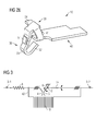
- FIGS. 2A to 2E different embodiments of the magnetic yoke 15 according to the invention are shown schematically.
- a magnetic yoke generally serves to bundle the magnetic field generated by the coil 8 in such a way that the force acting on the armature-tappet unit is amplified.
- the in the FIGS. 2A to 2E All embodiments of the magnetic yoke 15 shown have a coupling region 20, a fixed contact region 30 and a quenching chamber region 40.
- the coupling region 20 serves the mechanical coupling of the magnetic yoke 15 with a housing of the protective switching device 1.
- the coupling region 20 continues to serve the electrical and / or magnetic coupling of the magnetic yoke 15 with the coil 8 of the short-circuit release system of the protection device 1.
- the coupling region 20 a Have opening 21, through which the plunger 9 (see Fig.1 ) is guided to act on the moving contact 5 and on the Bewegtempo 6.
- a connection region 24 formed on the coupling region 20 serves to electrically contact the coil 8, for example by means of welding or brazing.
- the fixed contact region 30 is connected at its first end 31 in one piece with the coupling region 20 and forms the fixed contact 4 (see Fig.1 ) of the protective switching device 1.
- a contact element 34 is fixed to the fixed contact region 30, which with another, on the moving contact 5 (see Fig.1 ) formed contact element and forms the switching contact of the protective switching device 1.
- the use of separate contact elements allows - with regard to the materials used - a more flexible design of the individual components, in which the components are adaptable with respect to their material properties to the respective function of the component.
- the second end 32 of the fixed contact region 30 is formed as a free end. This results in the advantage that the fixed contact region 30 is less rigid and can spring to a limited extent.
- the switching contact is suddenly closed, as occurs, for example, when using a snap-action switching mechanism, a rebound of the moving contact 5 is prevented or at least reduced.
- the free second end 32 is formed as a contact horn 33.
- the quenching chamber region 40 is also connected in one piece with the coupling region 20 via a connecting region 41 and forms the upper termination of the arc quenching chamber 10 (see FIG Fig.1 ) of the protective switching device 1.
- the extinguishing chamber area 40 serves as a bypass current path 42 (see Figure 6), which is energized when a short circuit occurs only after a commutation of the arc 7 of the fixed contact region 30 to the quenching chamber region 40.
- This effect is achieved in that the second end 32 of the fixed contact region 30 is formed as a free end. This necessarily means that the free second end 32 is not directly electrically connected to the quenching chamber region 40.
- the fixed contact region 30 is thermally stressed only during the period from the formation of the arc 7 to its commutation on the quenching chamber region 40, but not during the period from commutation to the final extinction of the arc 7 in the arc quenching chamber 10th During the latter period, the electric (short-circuit) current flows from the input terminal 3-1 via the coil 8 and the quenching chamber area 40 and the arc 7 to the output terminal 3-2. The fixed contact region 30 is no longer energized in this case.
- FIG. 2A shows in a first embodiment, a basic shape of the magnetic yoke 15, in which the coupling region 20 is designed only for mounting with the coil 8.
- FIG. 2B illustrated second embodiment, a magnetic yoke 15 with a coupling region 20 to which an additional magnetic core 23 is attached.
- the magnetic field generated by the energized coil 8 is bundled, whereby the force acting on the armature plunger unit of the short-circuit release magnetic force is amplified.
- FIG. 2C such as FIG. 2D
- Illustrated embodiments show a magnetic yoke 15 with a magnetic core 24 for amplifying the force acting on the armature plunger unit magnetic force.
- FIG. 2D Illustrated embodiments show a magnetic yoke 15 with a magnetic core 24 for amplifying the force acting on the armature plunger unit magnetic force.
- the magnetic core 24 is not attached as an independent component to the coupling region 20, but integrally connected to the actual coupling region 20.
- FIG. 2E illustrated embodiment shows a magnetic yoke 15, the coupling region 20 is formed reduced and has no opening 21 for the implementation of the plunger 9. Rather, this area, ie the area of the opening 21, is completely omitted, so that the plunger 9 is guided past the magnetic yoke 15 above the coupling area 20.
- This embodiment is particularly interesting for short-circuit release systems, which operate without an additional magnetic core, since this significantly simplifies the assembly of the magnetic yoke 15.
- connection region 24 is formed for electrical contacting with the coil 8 the connecting portion 41 opposite to the coupling region 20, while the connection portion 24 in the in the FIGS. 2A to 2C illustrated embodiments is formed by the connecting portion 41 of the coupling region 20 with the quenching chamber region 40.
- FIG. 3 shows a schematic representation of an equivalent circuit diagram of the protective switching device 1 according to the invention when using the magnetic yoke according to the invention 15.
- the electric current flows from the input terminal 3-1 coming via the coil 8 of the short-circuit release and the closed switching contact to the output terminal 3-2 (upper current path) .
- the switching contact is opened, ie the moving contact 5 is moved away from the fixed contact 4 via the movable in the D point movable contact carrier 6.
- the result is an arc 7, which first burns between the fixed contact 4 and the moving contact 5.
- the switching contact area out in the direction of the quenching chamber 10th driven.
- the arc commutes from the fixed contact region 30 to the quenching chamber region 40 of the magnet yoke 15.
- This quenching chamber region 40 now acts as a bypass current path 42, ie during the period from the commutation of the arc 7 until its extinction, the electrical (short-circuit) current flows from the input terminal 3 -1 via the coil 8 and acting as a bypass current path 42 quenching chamber region 40 (lower current path), and further over the standing in or before the arc-quenching arc 10 arc 7 to the output terminal 3-2.
- the fixed contact region 30 of the magnetic yoke 15 is no longer energized from the time when the arc 7 commutes to the quenching chamber region 40.
- the thermal load of the fixed contact region 30 can thereby be significantly reduced.
Landscapes
- Physics & Mathematics (AREA)
- Electromagnetism (AREA)
- Arc-Extinguishing Devices That Are Switches (AREA)
- Electromagnets (AREA)
- Breakers (AREA)
Applications Claiming Priority (1)
| Application Number | Priority Date | Filing Date | Title |
|---|---|---|---|
| DE102014215007.8A DE102014215007A1 (de) | 2014-07-30 | 2014-07-30 | Schutzschaltgerät und Magnetjoch |
Publications (2)
| Publication Number | Publication Date |
|---|---|
| EP2980822A1 true EP2980822A1 (fr) | 2016-02-03 |
| EP2980822B1 EP2980822B1 (fr) | 2020-03-04 |
Family
ID=53267218
Family Applications (1)
| Application Number | Title | Priority Date | Filing Date |
|---|---|---|---|
| EP15167305.0A Active EP2980822B1 (fr) | 2014-07-30 | 2015-05-12 | Appareil de commutation de protection et culasse magnétique |
Country Status (3)
| Country | Link |
|---|---|
| EP (1) | EP2980822B1 (fr) |
| CN (1) | CN105321749B (fr) |
| DE (1) | DE102014215007A1 (fr) |
Cited By (24)
| Publication number | Priority date | Publication date | Assignee | Title |
|---|---|---|---|---|
| CN106206195A (zh) * | 2016-08-31 | 2016-12-07 | 厦门宏发开关设备有限公司 | 电磁脱扣装置以及电磁断路器 |
| CN107958829A (zh) * | 2017-12-08 | 2018-04-24 | 厦门宏发开关设备有限公司 | 一种n极静触头及其带n极的断路器 |
| DE102017212033A1 (de) | 2017-07-13 | 2019-01-17 | Siemens Aktiengesellschaft | Gleichstrom-Lichtbogenlöschvorrichtung und elektromechanisches Gleichstrom-Schaltgerät |
| DE102017214557A1 (de) | 2017-08-21 | 2019-02-21 | Siemens Aktiengesellschaft | Elektromechanisches Schutzschaltgerät |
| DE102020200993A1 (de) | 2020-01-28 | 2021-07-29 | Siemens Aktiengesellschaft | Fernantrieb, Anordnung mit einem Fernantrieb sowie Verfahren |
| DE102019220444B4 (de) | 2019-12-20 | 2021-08-05 | Siemens Aktiengesellschaft | Fernantrieb und Parametrier-Verfahren |
| EP3944434A1 (fr) | 2020-07-22 | 2022-01-26 | Siemens Aktiengesellschaft | Dispositif de fixation et appareil encastrable en série |
| DE102020210028A1 (de) | 2020-08-07 | 2022-02-10 | Siemens Aktiengesellschaft | Bedienerunabhängiges Kompaktsprungschaltwerk und elektromechanisches Schutzschaltgerät |
| DE102020211531A1 (de) | 2020-09-15 | 2022-03-17 | Siemens Aktiengesellschaft | Niederspannungs-Schutzschaltgerät |
| DE102020214192A1 (de) | 2020-11-11 | 2022-05-12 | Siemens Aktiengesellschaft | Kombinierte Kurzschluss-Überlast-Auslösevorrichtung und elektromechanisches Schutzschaltgerät |
| DE102021201159A1 (de) | 2021-02-08 | 2022-08-11 | Siemens Aktiengesellschaft | Isolierstoffgehäuse und Kompakt-Leitungsschutzschalter |
| DE102021202664A1 (de) | 2021-03-18 | 2022-09-22 | Siemens Aktiengesellschaft | Kompakt-Leitungsschutzschalter |
| EP4131297A1 (fr) | 2021-08-05 | 2023-02-08 | Siemens Aktiengesellschaft | Tiroir-transformateur sommateur de courant, disjoncteur-détecteur de fuites à la terre et procédé de montage |
| DE102021208516A1 (de) | 2021-08-05 | 2023-02-09 | Siemens Aktiengesellschaft | Summenstromwandler und Fehlerstromschutzschalter |
| DE102021208518A1 (de) | 2021-08-05 | 2023-02-09 | Siemens Aktiengesellschaft | Isolierstoffgehäuse und Niederspannungs-Schutzschaltgerät |
| DE102022200296A1 (de) | 2022-01-13 | 2023-07-13 | Siemens Aktiengesellschaft | Einpoliges Gehäusemodul und Niederspannungs-Schutzschaltgerät |
| DE102022200297A1 (de) | 2022-01-13 | 2023-07-13 | Siemens Aktiengesellschaft | Niederspannungs-Schutzschaltgerät und Montageverfahren |
| WO2023169804A1 (fr) | 2022-03-08 | 2023-09-14 | Siemens Aktiengesellschaft | Dispositif monté sur rail à commutation électronique et boîtier de matériau isolant |
| EP4258310A1 (fr) | 2022-04-06 | 2023-10-11 | Siemens Aktiengesellschaft | Module de boîtier, boîtier en matière isolante et appareil de commutation de protection |
| DE102022204329A1 (de) | 2022-05-02 | 2023-11-02 | Siemens Aktiengesellschaft | Modulares Isolierstoffgehäuse und mehrpoliges modulares Reiheneinbaugerät |
| WO2023247255A1 (fr) | 2022-06-21 | 2023-12-28 | Siemens Aktiengesellschaft | Dispositif disjoncteur basse tension |
| EP4312243A1 (fr) | 2022-07-28 | 2024-01-31 | Siemens Aktiengesellschaft | Ensemble transformateur sommateur de courant à tiroir, appareil à montage en série et procédé d'assemblage |
| DE102022208674A1 (de) | 2022-08-22 | 2024-02-22 | Siemens Aktiengesellschaft | Modular gebildetes, mehrpoliges Reiheneinbaugerät |
| DE102023200524B3 (de) | 2023-01-24 | 2024-05-29 | Siemens Aktiengesellschaft | Anschlussklemme und Reiheneinbaugerät |
Families Citing this family (1)
| Publication number | Priority date | Publication date | Assignee | Title |
|---|---|---|---|---|
| CN107123577B (zh) * | 2017-07-01 | 2019-11-08 | 中欧电气有限公司 | 小型智能永磁断路器 |
Citations (3)
| Publication number | Priority date | Publication date | Assignee | Title |
|---|---|---|---|---|
| DE102006026064A1 (de) * | 2006-06-03 | 2007-12-06 | Moeller Gmbh | Elektrische Schaltanordnung und Montageverfahren |
| DE102010019430A1 (de) * | 2010-05-05 | 2011-11-10 | Siemens Aktiengesellschaft | Schutzschaltgerät zum Überwachen eines Stromkreises |
| DE102011089234A1 (de) * | 2010-12-21 | 2012-06-21 | Siemens Aktiengesellschaft | Lichtbogen-Löschvorrichtung und Schutzschaltgerät |
Family Cites Families (5)
| Publication number | Priority date | Publication date | Assignee | Title |
|---|---|---|---|---|
| DE10126854A1 (de) * | 2001-06-01 | 2002-12-19 | Siemens Ag | Magnetjoch eines elektromagnetischen Auslösers |
| DE102009021771A1 (de) * | 2009-05-18 | 2010-11-25 | Abb Ag | Elektromagnetischer Auslöser und Schaltgerät |
| CN103681143A (zh) * | 2013-09-30 | 2014-03-26 | 长城电器集团有限公司 | 一种断路器电磁装置 |
| CN203596328U (zh) * | 2013-12-06 | 2014-05-14 | 童春雪 | 小型断路器 |
| CN103871796A (zh) * | 2014-03-19 | 2014-06-18 | 云南追梦科技有限公司 | 小型断路器的增磁导弧装置及具有该装置的小型断路器 |
-
2014
- 2014-07-30 DE DE102014215007.8A patent/DE102014215007A1/de not_active Withdrawn
-
2015
- 2015-05-12 EP EP15167305.0A patent/EP2980822B1/fr active Active
- 2015-07-30 CN CN201510457137.4A patent/CN105321749B/zh active Active
Patent Citations (3)
| Publication number | Priority date | Publication date | Assignee | Title |
|---|---|---|---|---|
| DE102006026064A1 (de) * | 2006-06-03 | 2007-12-06 | Moeller Gmbh | Elektrische Schaltanordnung und Montageverfahren |
| DE102010019430A1 (de) * | 2010-05-05 | 2011-11-10 | Siemens Aktiengesellschaft | Schutzschaltgerät zum Überwachen eines Stromkreises |
| DE102011089234A1 (de) * | 2010-12-21 | 2012-06-21 | Siemens Aktiengesellschaft | Lichtbogen-Löschvorrichtung und Schutzschaltgerät |
Cited By (38)
| Publication number | Priority date | Publication date | Assignee | Title |
|---|---|---|---|---|
| CN106206195A (zh) * | 2016-08-31 | 2016-12-07 | 厦门宏发开关设备有限公司 | 电磁脱扣装置以及电磁断路器 |
| DE102017212033A1 (de) | 2017-07-13 | 2019-01-17 | Siemens Aktiengesellschaft | Gleichstrom-Lichtbogenlöschvorrichtung und elektromechanisches Gleichstrom-Schaltgerät |
| DE102017214557A1 (de) | 2017-08-21 | 2019-02-21 | Siemens Aktiengesellschaft | Elektromechanisches Schutzschaltgerät |
| CN107958829A (zh) * | 2017-12-08 | 2018-04-24 | 厦门宏发开关设备有限公司 | 一种n极静触头及其带n极的断路器 |
| CN107958829B (zh) * | 2017-12-08 | 2021-09-07 | 厦门宏发开关设备有限公司 | 一种n极静触头及其带n极的断路器 |
| DE102019220444B4 (de) | 2019-12-20 | 2021-08-05 | Siemens Aktiengesellschaft | Fernantrieb und Parametrier-Verfahren |
| DE102020200993A1 (de) | 2020-01-28 | 2021-07-29 | Siemens Aktiengesellschaft | Fernantrieb, Anordnung mit einem Fernantrieb sowie Verfahren |
| DE102020200993B4 (de) | 2020-01-28 | 2023-06-01 | Siemens Aktiengesellschaft | Fernantrieb, Anordnung mit einem Fernantrieb sowie Verfahren |
| DE102020209257A1 (de) | 2020-07-22 | 2022-01-27 | Siemens Aktiengesellschaft | Befestigungsvorrichtung und Reiheneinbaugerät |
| EP3944434A1 (fr) | 2020-07-22 | 2022-01-26 | Siemens Aktiengesellschaft | Dispositif de fixation et appareil encastrable en série |
| DE102020210028A1 (de) | 2020-08-07 | 2022-02-10 | Siemens Aktiengesellschaft | Bedienerunabhängiges Kompaktsprungschaltwerk und elektromechanisches Schutzschaltgerät |
| WO2022028849A1 (fr) | 2020-08-07 | 2022-02-10 | Siemens Aktiengesellschaft | Mécanisme de commutation à ressort compact indépendant de l'opérateur et dispositif de commutation de protection électromécanique |
| DE102020211531A1 (de) | 2020-09-15 | 2022-03-17 | Siemens Aktiengesellschaft | Niederspannungs-Schutzschaltgerät |
| DE102020214192A1 (de) | 2020-11-11 | 2022-05-12 | Siemens Aktiengesellschaft | Kombinierte Kurzschluss-Überlast-Auslösevorrichtung und elektromechanisches Schutzschaltgerät |
| DE102021201159A1 (de) | 2021-02-08 | 2022-08-11 | Siemens Aktiengesellschaft | Isolierstoffgehäuse und Kompakt-Leitungsschutzschalter |
| WO2022167538A1 (fr) | 2021-02-08 | 2022-08-11 | Siemens Aktiengesellschaft | Boîtier en matériau isolant et disjoncteur compact |
| DE102021202664A1 (de) | 2021-03-18 | 2022-09-22 | Siemens Aktiengesellschaft | Kompakt-Leitungsschutzschalter |
| DE102021208516A1 (de) | 2021-08-05 | 2023-02-09 | Siemens Aktiengesellschaft | Summenstromwandler und Fehlerstromschutzschalter |
| DE102021208514A1 (de) | 2021-08-05 | 2023-02-09 | Siemens Aktiengesellschaft | Einschub-Summenstromwandler, Fehlerstromschutzschalter und Montageverfahren |
| DE102021208518A1 (de) | 2021-08-05 | 2023-02-09 | Siemens Aktiengesellschaft | Isolierstoffgehäuse und Niederspannungs-Schutzschaltgerät |
| EP4138112A1 (fr) | 2021-08-05 | 2023-02-22 | Siemens Aktiengesellschaft | Boîtier en matière isolante et disjoncteur de protection basse tension |
| EP4131297A1 (fr) | 2021-08-05 | 2023-02-08 | Siemens Aktiengesellschaft | Tiroir-transformateur sommateur de courant, disjoncteur-détecteur de fuites à la terre et procédé de montage |
| DE102022200296A1 (de) | 2022-01-13 | 2023-07-13 | Siemens Aktiengesellschaft | Einpoliges Gehäusemodul und Niederspannungs-Schutzschaltgerät |
| DE102022200297A1 (de) | 2022-01-13 | 2023-07-13 | Siemens Aktiengesellschaft | Niederspannungs-Schutzschaltgerät und Montageverfahren |
| EP4213175A1 (fr) | 2022-01-13 | 2023-07-19 | Siemens Aktiengesellschaft | Disjoncteur basse tension avec circuit imprime et prise de tension et procédé de montage |
| EP4213174A1 (fr) | 2022-01-13 | 2023-07-19 | Siemens Aktiengesellschaft | Module de boîtier unipolaire et disjoncteur basse tension |
| WO2023169804A1 (fr) | 2022-03-08 | 2023-09-14 | Siemens Aktiengesellschaft | Dispositif monté sur rail à commutation électronique et boîtier de matériau isolant |
| DE102022202311A1 (de) | 2022-03-08 | 2023-09-14 | Siemens Aktiengesellschaft | Elektronisch schaltendes Reiheneinbaugerät und Isolierstoffgehäuse |
| EP4258310A1 (fr) | 2022-04-06 | 2023-10-11 | Siemens Aktiengesellschaft | Module de boîtier, boîtier en matière isolante et appareil de commutation de protection |
| DE102022203408A1 (de) | 2022-04-06 | 2023-10-12 | Siemens Aktiengesellschaft | Gehäusemodul, Isolierstoffgehäuse und Schutzschaltgerät |
| DE102022204329A1 (de) | 2022-05-02 | 2023-11-02 | Siemens Aktiengesellschaft | Modulares Isolierstoffgehäuse und mehrpoliges modulares Reiheneinbaugerät |
| EP4274041A1 (fr) | 2022-05-02 | 2023-11-08 | Siemens Aktiengesellschaft | Boîtier isolant modulaire et appareil modulaire multipolaire à montage en série |
| WO2023247255A1 (fr) | 2022-06-21 | 2023-12-28 | Siemens Aktiengesellschaft | Dispositif disjoncteur basse tension |
| EP4312243A1 (fr) | 2022-07-28 | 2024-01-31 | Siemens Aktiengesellschaft | Ensemble transformateur sommateur de courant à tiroir, appareil à montage en série et procédé d'assemblage |
| DE102022207779A1 (de) | 2022-07-28 | 2024-02-08 | Siemens Aktiengesellschaft | Einschub-Summenstromwandler-Baugruppe, Reiheneinbaugerät und Montageverfahren |
| DE102022208674A1 (de) | 2022-08-22 | 2024-02-22 | Siemens Aktiengesellschaft | Modular gebildetes, mehrpoliges Reiheneinbaugerät |
| WO2024041855A1 (fr) | 2022-08-22 | 2024-02-29 | Siemens Aktiengesellschaft | Dispositif modulaire monté sur rail multipolaire |
| DE102023200524B3 (de) | 2023-01-24 | 2024-05-29 | Siemens Aktiengesellschaft | Anschlussklemme und Reiheneinbaugerät |
Also Published As
| Publication number | Publication date |
|---|---|
| DE102014215007A1 (de) | 2016-02-04 |
| EP2980822B1 (fr) | 2020-03-04 |
| CN105321749A (zh) | 2016-02-10 |
| CN105321749B (zh) | 2019-08-30 |
Similar Documents
| Publication | Publication Date | Title |
|---|---|---|
| EP2980822B1 (fr) | Appareil de commutation de protection et culasse magnétique | |
| EP2685482B1 (fr) | Appareil de commutation de protection et culasse magnétique | |
| DE102013211539B4 (de) | Schaltmechanik und elektromechanisches Schutzschaltgerät | |
| DE102015217704A1 (de) | Lichtbogen-Löschvorrichtung und Schutzschaltgerät | |
| DE3021867A1 (de) | Selbstschalter | |
| EP3428942A1 (fr) | Dispositif d'extinction d'arc de courant continu et appareil de commutation de courant continu électromécanique | |
| DE102011002714B4 (de) | Schutzschaltgerät | |
| DE102017202370B4 (de) | Lichtbogenlöschvorrichtung, elektromechanisches Schutzschaltgerät und Herstellverfahren | |
| EP2830076B1 (fr) | Appareil de commutation | |
| EP2989653B1 (fr) | Contacteur avec un mécanisme de déclenchement amélioré en cas de court-circuit | |
| EP2313905A1 (fr) | Dispositif de commutation | |
| DE102017204942B4 (de) | Elektromechanisches Schutzschaltgerät | |
| EP3258231A1 (fr) | Appareil de protection électromécanique comprenant un dispositif de déclenchement contre la surcharge | |
| EP3055875B1 (fr) | Appareil de commutation pourvu d'un élément amortisseur pour le système de contact lors d'une mise en circuit brusque | |
| EP2541574B1 (fr) | Disjoncteur électrique à double point de rupture | |
| EP3327742B1 (fr) | Dispositif d'extinction d'un arc électrique et disjoncteur électromécanique | |
| DE102009035299B4 (de) | Kontaktsystem und Schaltgerät | |
| DE102016203506A1 (de) | Auslösevorrichtung und elektromechanisches Schutzschaltgerät | |
| DE102016203508B4 (de) | Auslösevorrichtung und elektromechanisches Schutzschaltgerät | |
| EP3889986B1 (fr) | Disjoncteur de protection compact électromécanique | |
| DE102017214557A1 (de) | Elektromechanisches Schutzschaltgerät | |
| DE102011079593B4 (de) | Elektromechanisches Schutzschaltgerät | |
| DE102017202790B4 (de) | Elektromechanisches Schutzschaltgerät | |
| EP2431993B1 (fr) | Commutateur modulaire basse tension | |
| DE102015217694A1 (de) | Lichtbogen-Löschvorrichtung und Schutzschaltgerät |
Legal Events
| Date | Code | Title | Description |
|---|---|---|---|
| PUAI | Public reference made under article 153(3) epc to a published international application that has entered the european phase |
Free format text: ORIGINAL CODE: 0009012 |
|
| AK | Designated contracting states |
Kind code of ref document: A1 Designated state(s): AL AT BE BG CH CY CZ DE DK EE ES FI FR GB GR HR HU IE IS IT LI LT LU LV MC MK MT NL NO PL PT RO RS SE SI SK SM TR |
|
| AX | Request for extension of the european patent |
Extension state: BA ME |
|
| 17P | Request for examination filed |
Effective date: 20160720 |
|
| RBV | Designated contracting states (corrected) |
Designated state(s): AL AT BE BG CH CY CZ DE DK EE ES FI FR GB GR HR HU IE IS IT LI LT LU LV MC MK MT NL NO PL PT RO RS SE SI SK SM TR |
|
| RAP1 | Party data changed (applicant data changed or rights of an application transferred) |
Owner name: SIEMENS AKTIENGESELLSCHAFT |
|
| GRAP | Despatch of communication of intention to grant a patent |
Free format text: ORIGINAL CODE: EPIDOSNIGR1 |
|
| STAA | Information on the status of an ep patent application or granted ep patent |
Free format text: STATUS: GRANT OF PATENT IS INTENDED |
|
| INTG | Intention to grant announced |
Effective date: 20191010 |
|
| GRAS | Grant fee paid |
Free format text: ORIGINAL CODE: EPIDOSNIGR3 |
|
| GRAA | (expected) grant |
Free format text: ORIGINAL CODE: 0009210 |
|
| STAA | Information on the status of an ep patent application or granted ep patent |
Free format text: STATUS: THE PATENT HAS BEEN GRANTED |
|
| AK | Designated contracting states |
Kind code of ref document: B1 Designated state(s): AL AT BE BG CH CY CZ DE DK EE ES FI FR GB GR HR HU IE IS IT LI LT LU LV MC MK MT NL NO PL PT RO RS SE SI SK SM TR |
|
| REG | Reference to a national code |
Ref country code: GB Ref legal event code: FG4D Free format text: NOT ENGLISH |
|
| REG | Reference to a national code |
Ref country code: CH Ref legal event code: EP |
|
| REG | Reference to a national code |
Ref country code: AT Ref legal event code: REF Ref document number: 1241324 Country of ref document: AT Kind code of ref document: T Effective date: 20200315 |
|
| REG | Reference to a national code |
Ref country code: DE Ref legal event code: R096 Ref document number: 502015011906 Country of ref document: DE |
|
| REG | Reference to a national code |
Ref country code: IE Ref legal event code: FG4D Free format text: LANGUAGE OF EP DOCUMENT: GERMAN |
|
| PG25 | Lapsed in a contracting state [announced via postgrant information from national office to epo] |
Ref country code: RS Free format text: LAPSE BECAUSE OF FAILURE TO SUBMIT A TRANSLATION OF THE DESCRIPTION OR TO PAY THE FEE WITHIN THE PRESCRIBED TIME-LIMIT Effective date: 20200304 Ref country code: FI Free format text: LAPSE BECAUSE OF FAILURE TO SUBMIT A TRANSLATION OF THE DESCRIPTION OR TO PAY THE FEE WITHIN THE PRESCRIBED TIME-LIMIT Effective date: 20200304 Ref country code: NO Free format text: LAPSE BECAUSE OF FAILURE TO SUBMIT A TRANSLATION OF THE DESCRIPTION OR TO PAY THE FEE WITHIN THE PRESCRIBED TIME-LIMIT Effective date: 20200604 |
|
| REG | Reference to a national code |
Ref country code: NL Ref legal event code: MP Effective date: 20200304 |
|
| PG25 | Lapsed in a contracting state [announced via postgrant information from national office to epo] |
Ref country code: HR Free format text: LAPSE BECAUSE OF FAILURE TO SUBMIT A TRANSLATION OF THE DESCRIPTION OR TO PAY THE FEE WITHIN THE PRESCRIBED TIME-LIMIT Effective date: 20200304 Ref country code: BG Free format text: LAPSE BECAUSE OF FAILURE TO SUBMIT A TRANSLATION OF THE DESCRIPTION OR TO PAY THE FEE WITHIN THE PRESCRIBED TIME-LIMIT Effective date: 20200604 Ref country code: LV Free format text: LAPSE BECAUSE OF FAILURE TO SUBMIT A TRANSLATION OF THE DESCRIPTION OR TO PAY THE FEE WITHIN THE PRESCRIBED TIME-LIMIT Effective date: 20200304 Ref country code: GR Free format text: LAPSE BECAUSE OF FAILURE TO SUBMIT A TRANSLATION OF THE DESCRIPTION OR TO PAY THE FEE WITHIN THE PRESCRIBED TIME-LIMIT Effective date: 20200605 Ref country code: SE Free format text: LAPSE BECAUSE OF FAILURE TO SUBMIT A TRANSLATION OF THE DESCRIPTION OR TO PAY THE FEE WITHIN THE PRESCRIBED TIME-LIMIT Effective date: 20200304 |
|
| REG | Reference to a national code |
Ref country code: LT Ref legal event code: MG4D |
|
| PG25 | Lapsed in a contracting state [announced via postgrant information from national office to epo] |
Ref country code: NL Free format text: LAPSE BECAUSE OF FAILURE TO SUBMIT A TRANSLATION OF THE DESCRIPTION OR TO PAY THE FEE WITHIN THE PRESCRIBED TIME-LIMIT Effective date: 20200304 |
|
| PG25 | Lapsed in a contracting state [announced via postgrant information from national office to epo] |
Ref country code: LT Free format text: LAPSE BECAUSE OF FAILURE TO SUBMIT A TRANSLATION OF THE DESCRIPTION OR TO PAY THE FEE WITHIN THE PRESCRIBED TIME-LIMIT Effective date: 20200304 Ref country code: SM Free format text: LAPSE BECAUSE OF FAILURE TO SUBMIT A TRANSLATION OF THE DESCRIPTION OR TO PAY THE FEE WITHIN THE PRESCRIBED TIME-LIMIT Effective date: 20200304 Ref country code: PT Free format text: LAPSE BECAUSE OF FAILURE TO SUBMIT A TRANSLATION OF THE DESCRIPTION OR TO PAY THE FEE WITHIN THE PRESCRIBED TIME-LIMIT Effective date: 20200729 Ref country code: EE Free format text: LAPSE BECAUSE OF FAILURE TO SUBMIT A TRANSLATION OF THE DESCRIPTION OR TO PAY THE FEE WITHIN THE PRESCRIBED TIME-LIMIT Effective date: 20200304 Ref country code: IS Free format text: LAPSE BECAUSE OF FAILURE TO SUBMIT A TRANSLATION OF THE DESCRIPTION OR TO PAY THE FEE WITHIN THE PRESCRIBED TIME-LIMIT Effective date: 20200704 Ref country code: RO Free format text: LAPSE BECAUSE OF FAILURE TO SUBMIT A TRANSLATION OF THE DESCRIPTION OR TO PAY THE FEE WITHIN THE PRESCRIBED TIME-LIMIT Effective date: 20200304 Ref country code: CZ Free format text: LAPSE BECAUSE OF FAILURE TO SUBMIT A TRANSLATION OF THE DESCRIPTION OR TO PAY THE FEE WITHIN THE PRESCRIBED TIME-LIMIT Effective date: 20200304 Ref country code: ES Free format text: LAPSE BECAUSE OF FAILURE TO SUBMIT A TRANSLATION OF THE DESCRIPTION OR TO PAY THE FEE WITHIN THE PRESCRIBED TIME-LIMIT Effective date: 20200304 Ref country code: SK Free format text: LAPSE BECAUSE OF FAILURE TO SUBMIT A TRANSLATION OF THE DESCRIPTION OR TO PAY THE FEE WITHIN THE PRESCRIBED TIME-LIMIT Effective date: 20200304 |
|
| REG | Reference to a national code |
Ref country code: DE Ref legal event code: R097 Ref document number: 502015011906 Country of ref document: DE |
|
| PLBE | No opposition filed within time limit |
Free format text: ORIGINAL CODE: 0009261 |
|
| STAA | Information on the status of an ep patent application or granted ep patent |
Free format text: STATUS: NO OPPOSITION FILED WITHIN TIME LIMIT |
|
| PG25 | Lapsed in a contracting state [announced via postgrant information from national office to epo] |
Ref country code: IT Free format text: LAPSE BECAUSE OF FAILURE TO SUBMIT A TRANSLATION OF THE DESCRIPTION OR TO PAY THE FEE WITHIN THE PRESCRIBED TIME-LIMIT Effective date: 20200304 Ref country code: DK Free format text: LAPSE BECAUSE OF FAILURE TO SUBMIT A TRANSLATION OF THE DESCRIPTION OR TO PAY THE FEE WITHIN THE PRESCRIBED TIME-LIMIT Effective date: 20200304 Ref country code: MC Free format text: LAPSE BECAUSE OF FAILURE TO SUBMIT A TRANSLATION OF THE DESCRIPTION OR TO PAY THE FEE WITHIN THE PRESCRIBED TIME-LIMIT Effective date: 20200304 Ref country code: LI Free format text: LAPSE BECAUSE OF NON-PAYMENT OF DUE FEES Effective date: 20200531 Ref country code: CH Free format text: LAPSE BECAUSE OF NON-PAYMENT OF DUE FEES Effective date: 20200531 |
|
| 26N | No opposition filed |
Effective date: 20201207 |
|
| PG25 | Lapsed in a contracting state [announced via postgrant information from national office to epo] |
Ref country code: SI Free format text: LAPSE BECAUSE OF FAILURE TO SUBMIT A TRANSLATION OF THE DESCRIPTION OR TO PAY THE FEE WITHIN THE PRESCRIBED TIME-LIMIT Effective date: 20200304 Ref country code: PL Free format text: LAPSE BECAUSE OF FAILURE TO SUBMIT A TRANSLATION OF THE DESCRIPTION OR TO PAY THE FEE WITHIN THE PRESCRIBED TIME-LIMIT Effective date: 20200304 |
|
| REG | Reference to a national code |
Ref country code: BE Ref legal event code: MM Effective date: 20200531 |
|
| GBPC | Gb: european patent ceased through non-payment of renewal fee |
Effective date: 20200604 |
|
| PG25 | Lapsed in a contracting state [announced via postgrant information from national office to epo] |
Ref country code: LU Free format text: LAPSE BECAUSE OF NON-PAYMENT OF DUE FEES Effective date: 20200512 |
|
| PG25 | Lapsed in a contracting state [announced via postgrant information from national office to epo] |
Ref country code: IE Free format text: LAPSE BECAUSE OF NON-PAYMENT OF DUE FEES Effective date: 20200512 Ref country code: GB Free format text: LAPSE BECAUSE OF NON-PAYMENT OF DUE FEES Effective date: 20200604 Ref country code: FR Free format text: LAPSE BECAUSE OF NON-PAYMENT OF DUE FEES Effective date: 20200531 |
|
| PG25 | Lapsed in a contracting state [announced via postgrant information from national office to epo] |
Ref country code: BE Free format text: LAPSE BECAUSE OF NON-PAYMENT OF DUE FEES Effective date: 20200531 |
|
| REG | Reference to a national code |
Ref country code: AT Ref legal event code: MM01 Ref document number: 1241324 Country of ref document: AT Kind code of ref document: T Effective date: 20200512 |
|
| PG25 | Lapsed in a contracting state [announced via postgrant information from national office to epo] |
Ref country code: AT Free format text: LAPSE BECAUSE OF NON-PAYMENT OF DUE FEES Effective date: 20200512 |
|
| PG25 | Lapsed in a contracting state [announced via postgrant information from national office to epo] |
Ref country code: TR Free format text: LAPSE BECAUSE OF FAILURE TO SUBMIT A TRANSLATION OF THE DESCRIPTION OR TO PAY THE FEE WITHIN THE PRESCRIBED TIME-LIMIT Effective date: 20200304 Ref country code: MT Free format text: LAPSE BECAUSE OF FAILURE TO SUBMIT A TRANSLATION OF THE DESCRIPTION OR TO PAY THE FEE WITHIN THE PRESCRIBED TIME-LIMIT Effective date: 20200304 Ref country code: CY Free format text: LAPSE BECAUSE OF FAILURE TO SUBMIT A TRANSLATION OF THE DESCRIPTION OR TO PAY THE FEE WITHIN THE PRESCRIBED TIME-LIMIT Effective date: 20200304 |
|
| PG25 | Lapsed in a contracting state [announced via postgrant information from national office to epo] |
Ref country code: MK Free format text: LAPSE BECAUSE OF FAILURE TO SUBMIT A TRANSLATION OF THE DESCRIPTION OR TO PAY THE FEE WITHIN THE PRESCRIBED TIME-LIMIT Effective date: 20200304 Ref country code: AL Free format text: LAPSE BECAUSE OF FAILURE TO SUBMIT A TRANSLATION OF THE DESCRIPTION OR TO PAY THE FEE WITHIN THE PRESCRIBED TIME-LIMIT Effective date: 20200304 |
|
| PGFP | Annual fee paid to national office [announced via postgrant information from national office to epo] |
Ref country code: DE Payment date: 20220620 Year of fee payment: 9 |