EP2980234A1 - Valve seat - Google Patents
Valve seat Download PDFInfo
- Publication number
- EP2980234A1 EP2980234A1 EP15179135.7A EP15179135A EP2980234A1 EP 2980234 A1 EP2980234 A1 EP 2980234A1 EP 15179135 A EP15179135 A EP 15179135A EP 2980234 A1 EP2980234 A1 EP 2980234A1
- Authority
- EP
- European Patent Office
- Prior art keywords
- valve seat
- present disclosure
- valve
- wear resistance
- comparative example
- Prior art date
- Legal status (The legal status is an assumption and is not a legal conclusion. Google has not performed a legal analysis and makes no representation as to the accuracy of the status listed.)
- Granted
Links
Images

Classifications
-
- C—CHEMISTRY; METALLURGY
- C22—METALLURGY; FERROUS OR NON-FERROUS ALLOYS; TREATMENT OF ALLOYS OR NON-FERROUS METALS
- C22C—ALLOYS
- C22C33/00—Making ferrous alloys
- C22C33/02—Making ferrous alloys by powder metallurgy
- C22C33/0257—Making ferrous alloys by powder metallurgy characterised by the range of the alloying elements
- C22C33/0278—Making ferrous alloys by powder metallurgy characterised by the range of the alloying elements with at least one alloying element having a minimum content above 5%
- C22C33/0285—Making ferrous alloys by powder metallurgy characterised by the range of the alloying elements with at least one alloying element having a minimum content above 5% with Cr, Co, or Ni having a minimum content higher than 5%
-
- B—PERFORMING OPERATIONS; TRANSPORTING
- B22—CASTING; POWDER METALLURGY
- B22F—WORKING METALLIC POWDER; MANUFACTURE OF ARTICLES FROM METALLIC POWDER; MAKING METALLIC POWDER; APPARATUS OR DEVICES SPECIALLY ADAPTED FOR METALLIC POWDER
- B22F3/00—Manufacture of workpieces or articles from metallic powder characterised by the manner of compacting or sintering; Apparatus specially adapted therefor ; Presses and furnaces
- B22F3/24—After-treatment of workpieces or articles
- B22F3/26—Impregnating
-
- C—CHEMISTRY; METALLURGY
- C22—METALLURGY; FERROUS OR NON-FERROUS ALLOYS; TREATMENT OF ALLOYS OR NON-FERROUS METALS
- C22C—ALLOYS
- C22C38/00—Ferrous alloys, e.g. steel alloys
- C22C38/02—Ferrous alloys, e.g. steel alloys containing silicon
-
- C—CHEMISTRY; METALLURGY
- C22—METALLURGY; FERROUS OR NON-FERROUS ALLOYS; TREATMENT OF ALLOYS OR NON-FERROUS METALS
- C22C—ALLOYS
- C22C38/00—Ferrous alloys, e.g. steel alloys
- C22C38/04—Ferrous alloys, e.g. steel alloys containing manganese
-
- C—CHEMISTRY; METALLURGY
- C22—METALLURGY; FERROUS OR NON-FERROUS ALLOYS; TREATMENT OF ALLOYS OR NON-FERROUS METALS
- C22C—ALLOYS
- C22C38/00—Ferrous alloys, e.g. steel alloys
- C22C38/18—Ferrous alloys, e.g. steel alloys containing chromium
- C22C38/40—Ferrous alloys, e.g. steel alloys containing chromium with nickel
- C22C38/42—Ferrous alloys, e.g. steel alloys containing chromium with nickel with copper
-
- C—CHEMISTRY; METALLURGY
- C22—METALLURGY; FERROUS OR NON-FERROUS ALLOYS; TREATMENT OF ALLOYS OR NON-FERROUS METALS
- C22C—ALLOYS
- C22C38/00—Ferrous alloys, e.g. steel alloys
- C22C38/18—Ferrous alloys, e.g. steel alloys containing chromium
- C22C38/40—Ferrous alloys, e.g. steel alloys containing chromium with nickel
- C22C38/44—Ferrous alloys, e.g. steel alloys containing chromium with nickel with molybdenum or tungsten
-
- C—CHEMISTRY; METALLURGY
- C22—METALLURGY; FERROUS OR NON-FERROUS ALLOYS; TREATMENT OF ALLOYS OR NON-FERROUS METALS
- C22C—ALLOYS
- C22C38/00—Ferrous alloys, e.g. steel alloys
- C22C38/18—Ferrous alloys, e.g. steel alloys containing chromium
- C22C38/40—Ferrous alloys, e.g. steel alloys containing chromium with nickel
- C22C38/46—Ferrous alloys, e.g. steel alloys containing chromium with nickel with vanadium
-
- C—CHEMISTRY; METALLURGY
- C22—METALLURGY; FERROUS OR NON-FERROUS ALLOYS; TREATMENT OF ALLOYS OR NON-FERROUS METALS
- C22C—ALLOYS
- C22C38/00—Ferrous alloys, e.g. steel alloys
- C22C38/18—Ferrous alloys, e.g. steel alloys containing chromium
- C22C38/40—Ferrous alloys, e.g. steel alloys containing chromium with nickel
- C22C38/52—Ferrous alloys, e.g. steel alloys containing chromium with nickel with cobalt
-
- C—CHEMISTRY; METALLURGY
- C22—METALLURGY; FERROUS OR NON-FERROUS ALLOYS; TREATMENT OF ALLOYS OR NON-FERROUS METALS
- C22C—ALLOYS
- C22C38/00—Ferrous alloys, e.g. steel alloys
- C22C38/60—Ferrous alloys, e.g. steel alloys containing lead, selenium, tellurium, or antimony, or more than 0.04% by weight of sulfur
-
- C—CHEMISTRY; METALLURGY
- C22—METALLURGY; FERROUS OR NON-FERROUS ALLOYS; TREATMENT OF ALLOYS OR NON-FERROUS METALS
- C22C—ALLOYS
- C22C9/00—Alloys based on copper
-
- F—MECHANICAL ENGINEERING; LIGHTING; HEATING; WEAPONS; BLASTING
- F01—MACHINES OR ENGINES IN GENERAL; ENGINE PLANTS IN GENERAL; STEAM ENGINES
- F01L—CYCLICALLY OPERATING VALVES FOR MACHINES OR ENGINES
- F01L3/00—Lift-valve, i.e. cut-off apparatus with closure members having at least a component of their opening and closing motion perpendicular to the closing faces; Parts or accessories thereof
- F01L3/02—Selecting particular materials for valve-members or valve-seats; Valve-members or valve-seats composed of two or more materials
Definitions
- the present disclosure relates to a valve seat used for gas and diesel engines.
- valve seat which is one of the component parts of an engine, is closely adhered to a valve face, to provide an airtight combustion chamber. Since the valve seat is exposed to combustion gases at high temperature, and continuously contacted with the valve face, physical properties such as heat resistance and wear resistance are required.
- valve seat containing lead (Pb) is excellent in wear resistance and inexpensive, but includes lead (Pb) which causes environmental problems, the use range thereof is limited, and there is a problem in that the valve seat is melted in a high-temperature environment.
- valve seat by using a material including hard particles, such as Fe-Mo or Fe-Cr, has been proposed, but since the valve seat has extremely high wear resistance, there is a problem of damaging the valve which is a counterpart material.
- an object of the present disclosure is to provide a valve seat having excellent physical properties such as heat resistance and wear resistance.
- valve seat including 0.8 to 1.7 wt% of carbon (C), 0.5 to 1.5 wt% of silicon (Si), 0.5 to 1.5 wt% of manganese (Mn), 0.01 to 1.0 wt% of sulfur (S), 2.0 to 6.0 wt% of chromium (Cr), 7.0 to 16.0 wt% of molybdenum (Mo), 2.0 to 8.0 wt% of nickel (Ni), 0.01 to 3.0 wt% of tungsten (W), 0.01 to 1.0 wt% of vanadium (V), 14.0 to 25.0 wt% of cobalt (Co), and the balance of iron and impurities.
- the valve seat of the present disclosure may include a bainite structure, a structure including a silicide to which cobalt (Co) and molybdenum (Mo) are combined, a martensite structure including chromium composite carbide, and an austenite structure in the structure of the valve seat.
- the bainite structure is present in an amount of 2 to 12 vol% based on a total 100 vol% of the valve seat.
- a ratio of the area, which the bainite structure occupies at the cut surface formed by cutting the valve seat is 2 to 12% of the area of the cut surface.
- valve seat of the present disclosure may be a valve seat in which copper (Cu) or a copper alloy is infiltrated into pores in the structure.
- valve seat of the present disclosure may be a valve seat to which an iron-based sintered material is further combined.
- the valve seat of the present disclosure includes predetermined ranges of carbon, silicon, manganese, sulfur, chromium, molybdenum, nickel, tungsten, vanadium, and cobalt, and thus has excellent physical properties such as heat resistance and wear resistance. Furthermore, the valve seat of the present disclosure does not include lead (Pb), and thus, may also reduce the occurrence of environmental problems.
- the valve seat of the present disclosure includes predetermined ranges of carbon, silicon, manganese, sulfur, chromium, molybdenum, nickel, tungsten, vanadium, and cobalt, and thus has excellent physical properties such as heat resistance and wear resistance, and this will be described in detail as follows.
- the valve seat of the present disclosure includes 0.8 to 1.7 wt% of carbon (C) based on the total weight.
- C carbon
- the content of carbon is less than 0.8 wt%, the formation of the carbide structure in the structure of the valve seat deteriorates, and when the content of carbon exceeds 1.7 wt%, the ferrite structure remains in the structure of the valve seat, so that wear resistance of the valve seat may deteriorate. Therefore, it is preferred that carbon is included in the aforementioned range.
- the valve seat of the present disclosure includes 0.5 to 1.5 wt% of silicon (Si) based on the total weight.
- Si silicon
- the content of silicon is less than 0.5 wt%, production of a silicide produced by combining molybdenum (Mo) and cobalt (Co) deteriorates, so that wear resistance of the valve seat may deteriorate, and when the content of silicon exceeds 1.5 wt%, compressibility and sinterability may deteriorate when the valve seat is manufactured. Therefore, it is preferred that silicon is included in the aforementioned range.
- the valve seat of the present disclosure includes 0.5 to 1.5 wt% of manganese (Mn) based on the total weight.
- Mn manganese
- the valve seat of the present disclosure includes 0.01 to 1.0 wt% of sulfur (S) based on the total weight.
- S sulfur
- the content of sulfur is less than 0.01 wt%, production of a material combined to manganese deteriorates, and when the content of sulfur exceeds 1.0 wt%, the carbide structure is excessively formed in the structure of the valve seat, so that processability may deteriorate when the valve seat is manufactured. Therefore, it is preferred that sulfur is included in the aforementioned range.
- the valve seat of the present disclosure includes 2.0 to 6.0 wt% of chromium (Cr) based on the total weight.
- Cr chromium
- the content of chromium is less than 2.0 wt%, formation of the carbide structure in the structure of the valve seat deteriorates, so that wear resistance of the valve seat may deteriorate, and when the content of chromium exceeds 6.0 wt%, compressibility and sinterability deteriorate when the valve seat is manufactured, and wear resistance becomes excessively high, so that a degree that the valve, which is a counterpart material, is damaged may be increased. Therefore, it is preferred that chromium is included in the aforementioned range.
- the valve seat of the present disclosure includes 7.0 to 16.0 wt% of molybdenum (Mo) based on the total weight.
- Mo molybdenum
- production of the silicide to which cobalt and molybdenum are combined deteriorates, so that wear resistance of the valve seat may deteriorate, and when the content of molybdenum exceeds 16.0 wt%, compressibility may deteriorate when the valve seat is manufactured. Therefore, it is preferred that molybdenum is included in the aforementioned range.
- the valve seat of the present disclosure includes 2.0 to 8.0 wt% of nickel (Ni) based on the total weight.
- Ni nickel
- the content of nickel is less than 2.0 wt%, formation of the austenite structure in the structure of the valve seat deteriorates, so that wear resistance and heat resistance of the valve seat may deteriorate, and when the content of nickel exceeds 8.0 wt%, toughness of the valve seat becomes excessively high, and formation of the bainite structure deteriorates, so that wear resistance of the valve seat may deteriorate. Therefore, it is preferred that nickel is included in the aforementioned range.
- the valve seat of the present disclosure includes 0.01 to 3.0 wt% of tungsten (W) based on the total weight.
- W tungsten
- the content of tungsten is less than 0.01 wt%, formation of the carbide structure in the structure of the valve seat deteriorates, so that wear resistance of the valve seat may deteriorate, and when the content of tungsten exceeds 3.0 wt%, wear resistance of the valve seat becomes excessively high, so that a degree that the valve, which is a counterpart material, is damaged may be increased. Therefore, it is preferred that tungsten is included in the aforementioned range.
- the valve seat of the present disclosure includes 0.01 to 1.0 wt% of vanadium (V) based on the total weight.
- V vanadium
- the content of vanadium is less than 0.01 wt%, formation of the carbide structure in the structure of the valve seat deteriorates, so that wear resistance of the valve seat may deteriorate, and when the content of vanadium exceeds 1.0 wt%, compressibility and sinterability may deteriorate when the valve seat is manufactured. Therefore, it is preferred that vanadium is included in the aforementioned range.
- the valve seat of the present disclosure includes 14.0 to 25.0 wt% of cobalt (Co) based on the total weight.
- cobalt cobalt
- the content of cobalt is less than 14.0 wt%, production of the silicide to which cobalt and molybdenum are combined deteriorates, so that wear resistance and heat resistance of the valve seat may deteriorate, and when the content of cobalt exceeds 25.0 wt%, compressibility and sinterability may deteriorate when the valve seat is manufactured. Therefore, it is preferred that cobalt is included in the aforementioned range.
- the valve seat of the present disclosure includes the balance of iron (Fe) and impurities (for example, phosphorus (P), sulfur (S), and the like) in addition to the aforementioned components.
- Fe iron
- impurities for example, phosphorus (P), sulfur (S), and the like
- a bainite structure a structure including a silicide to which cobalt (Co) and molybdenum (Mo) are combined, a martensite structure including chromium composite carbide, and an austenite structure co-exist in the structure of the valve seat.
- the martensite structure including chromium composite carbide improves wear resistance of the valve seat, but when the structure is present alone, wear resistance of the valve seat becomes excessively high, so that a degree that the valve, which is a counterpart material, is damaged is increased.
- the bainite structure which increases wear resistance of the valve seat while less damaging the valve that is a counterpart material
- the austenite structure which secures toughness of the valve seat, co-exist along with the martensite structure in the valve seat of the present disclosure, it is possible to minimize a degree that the valve, which is a counterpart material, is damaged while wear resistance is excellent.
- valve seat of the present disclosure As a structure including a silicide to which cobalt (Co) and molybdenum (Mo) are combined exists in the structure of the valve seat of the present disclosure, combining properties between the structures are improved, so that the valve seat of the present disclosure also has excellent heat resistance.
- the bainite structure present in the structure of the valve seat of the present disclosure is present in an amount of 2 to 12 vol% based on the total 100 vol% of the valve seat.
- the volume of the bainite structure may be calculated by the following method, and in this case, the ratio of the calculated volume to the total volume of the valve seat is 2 to 12 vol%.
- the valve seat is cut in a direction vertical to the ground surface, and then the area of the bainite structure found at each cut surface is measured.
- the area of the bainite structure may be measured through an image analysis of the cut surface.
- the degree is preferably 2 to 12 vol%, and when a degree that the bainite structure occupies at the cut surface produced by cutting the valve seat is converted into area%, the degree is preferably 2 to 12% of the area of the cut surface.
- the valve seat of the present disclosure may further include copper (Cu) or a copper alloy (for example, Cu-Zn, Cu-Co, Cu-Fe-Mn, Cu-Fe-Mn-Zn, and the like) infiltrated into pores in the structure in order to increase combining properties of the structure.
- copper (Cu) or a copper alloy present in the structure of the valve seat is not particularly limited, but in consideration of processability of the valve seat, the content is preferably 1.0 to 25.0 wt% based on the total weight of the valve seat regardless of the chemical composition of the valve seat of the present disclosure.
- an iron-based sintered material may be further combined to the valve seat of the present disclosure in order to reduce the costs.
- the valve seat of the present disclosure may have a dual-layer structure in which a part, which is closely adhered to a valve face (a part which is contacted with the valve), is composed of the component and composition described above and a part, which is not closely adhered to the valve face (a part which is not contacted with the valve), is composed of an iron-based sintered material.
- the component and composition of the iron-based sintered material are not particularly limited, but 0.1 to 1.5 wt% of carbon (C) and 0.1 to 25 wt% of copper (Cu) are included based on the total weight of the iron-based sintered material, and the balance may be composed of iron (Fe) and impurities.
- the present disclosure provides an engine including the valve seat described above.
- the kind of engine of the present disclosure is not particularly limited, but the engine may be a gas or diesel engine.
- a valve seat having the shape as in FIG. 1 was molded by selecting the powder of each component through a powder metallurgical method, and then mixing and pressing the powder. Thereafter, the valve seat having the composition in the following Table 1 was each manufactured by sinteringvalve seat in a sintering furnace, and subjected the valve seat to post-processing (heat treatment). In this case, when the molded valve seat was sintered, a process of infiltrating copper (Cu) was added to Examples 6 to 9. Meanwhile, the composition of each valve seat manufactured was confirmed by an inductively-coupled plasma-mass spectrometer.
- Example 1 Classification Chemical Component (wt%) C Si Mn S Cr Mo Ni Cu Pb W V Co Fe / Impurities
- Example 2 1.2 1.0 1.0 0.6 4.3 12 4.5 - - 1.4 0.4 19 Bal.
- Example 3 1.0 0.9 1.0 0.5 3.1 10 5.0 - - 0.6 0.2 21 Bal.
- Example 4 1.3 1.4 1.0 0.5 2.8 15 5.0 - - 0.9 0.3 18 Bal.
- Example 5 1.1 0.8 1.1 0.5 5.6 9 3.7 - - 2.0 0.6 25 Bal.
- Example 6 1.2 1.0 1.0 0.5 3.6 11 4.4 5 - 1.4 0.4 21 Bal.
- Example 7 1.2 1.0 1.0 0.5 3.6 11 4.4 15 - 1.4 0.4 21 Bal.
- Example 8 1.2 1.0 1.0 0.5 3.6 11 4.4 25 - 1.4 0.4 21 Bal.
- Example 9 1.2 1.0 1.0 0.5 3.6 11 4.4 30 - 1.4 0.4 21 Bal.
- the valve seat having the composition in the following Table 2 was each manufactured by applying the method which is the same as in Example 1. In this case, a process of sintering the molded valve seat, and then impregnating lead (Pb) was added to Comparative Examples 5 and 9, and a process of infiltrating copper (Cu) when the molded valve seat was sintered was added to Comparative Examples 6, 8, 10, and 11. Meanwhile, the composition of each valve seat manufactured was confirmed by an inductively-coupled plasma-mass spectrometer. [Table 2] Classification Chemical Component (wt%) C Si Mn S Cr Mo Ni Cu Pb W V Co Fe / Impurities Comparative Example 1 1.2 0.3 1.0 0.5 1.7 4 5.3 - - 1.4 0.4 6 Bal.
- Comparative Example 2 1.4 1.4 1.1 0.6 6.5 16.5 3.4 - - 2.6 0.8 25.5 Bal.
- Comparative Example 3 1.2 0.2 1.0 0.5 1.3 2.5 6.0 - - 1.4 0.4 3 Bal.
- Comparative Example 4 1.4 0.4 1.1 0.6 6.7 18 4.0 - - 2.7 0.9 29 Bal.
- Comparative Example 5 1.0 - - - 3.0 5 - - 20 6.0 3.0 - Bal.
- Comparative Example 6 1.0 - - - 3.0 5 - 20 - 6.0 3.0 - Bal.
- Comparative Example 7 0.6 1.0 1.0 0.5 5.5 13 0.5 0.3 - 3.5 1.0 20 Bal.
- Comparative Example 8 1.0 1.1 1.1 0.5 5.0 15 0.6 15 - 2.5 1.5 25 Bal. Comparative Example 9 0.8 1.5 - - 1.0 8 1.0 3 10 - - 10 Bal. Comparative Example 10 1.0 1.0 1.2 0.6 1.5 12 0.2 12 - - - 15 Bal. Comparative Example 11 0.5 0.8 2.0 1.4 2.0 13 - 12 - - - 16 Bal.
- the valve seat manufactured in Example 1 was vertically cut (see FIG. 2 ), the cut surface was polished and etched, and then observed by an optical microscope (200 times magnification was applied), and the results are shown in FIG. 3 .
- a bainite structure a structure including a silicide to which cobalt (Co) and molybdenum (Mo) are combined, a martensite structure including chromium composite carbide, and an austenite structure co-exist in the structure of the valve seat.
- valve seat was cut in a direction vertical to the ground surface at A 1 , A 2 , and A 3 points (see FIG. 1 ) of each valve seat manufactured in Examples 1 to 5 and Comparative Examples 1 to 4, the cut surface was polished and etched, and then observed by an optical microscope to measure the area of the bainite structure found at each cut surface.
- the bainite structure is present in an amount of 2 to 12 vol% based on the total 100 vol% of the valve seat.
- valve seats (Examples 1 to 9) of the present disclosure have excellent wear resistance. Further, it can be confirmed that the rate of change in wear amount is low even though the temperature was increased from 150°C to 300°C, which supports that the valve seat of the present disclosure has excellent heat resistance.
- the post-processability was evaluated by the following method when the valve seats in Examples 1 and 6 to 9 were manufactured, and the results are shown in FIG. 4 .
- Example 9 As the content of copper (Cu) infiltrated in Example 9 is higher than those in Examples 1 and 6 to 8, the cutting amount is increased when the post-processing is performed. This supports that it is preferred that the content of copper (Cu) infiltrated does not exceed 25 wt% in consideration of post-processability.
Landscapes
- Chemical & Material Sciences (AREA)
- Engineering & Computer Science (AREA)
- Mechanical Engineering (AREA)
- Materials Engineering (AREA)
- Metallurgy (AREA)
- Organic Chemistry (AREA)
- General Engineering & Computer Science (AREA)
- Manufacturing & Machinery (AREA)
- Powder Metallurgy (AREA)
- Lift Valve (AREA)
Description
- The present disclosure relates to a valve seat used for gas and diesel engines.
- In general, a valve seat, which is one of the component parts of an engine, is closely adhered to a valve face, to provide an airtight combustion chamber. Since the valve seat is exposed to combustion gases at high temperature, and continuously contacted with the valve face, physical properties such as heat resistance and wear resistance are required.
- In order to secure the physical properties as described above, a technology of manufacturing a valve seat by containing lead (Pb) in materials for manufacturing the valve seat has been proposed in the related art. Since the valve seat containing lead (Pb) is excellent in wear resistance and inexpensive, but includes lead (Pb) which causes environmental problems, the use range thereof is limited, and there is a problem in that the valve seat is melted in a high-temperature environment.
- Further, a technology of manufacturing a valve seat by using a material including hard particles, such as Fe-Mo or Fe-Cr, has been proposed, but since the valve seat has extremely high wear resistance, there is a problem of damaging the valve which is a counterpart material.
- In order to solve the aforementioned problems, an object of the present disclosure is to provide a valve seat having excellent physical properties such as heat resistance and wear resistance.
- In order to achieve the aforementioned object, the present disclosure provides a valve seat including 0.8 to 1.7 wt% of carbon (C), 0.5 to 1.5 wt% of silicon (Si), 0.5 to 1.5 wt% of manganese (Mn), 0.01 to 1.0 wt% of sulfur (S), 2.0 to 6.0 wt% of chromium (Cr), 7.0 to 16.0 wt% of molybdenum (Mo), 2.0 to 8.0 wt% of nickel (Ni), 0.01 to 3.0 wt% of tungsten (W), 0.01 to 1.0 wt% of vanadium (V), 14.0 to 25.0 wt% of cobalt (Co), and the balance of iron and impurities.
- The valve seat of the present disclosure may include a bainite structure, a structure including a silicide to which cobalt (Co) and molybdenum (Mo) are combined, a martensite structure including chromium composite carbide, and an austenite structure in the structure of the valve seat.
- In this case, it is preferred that the bainite structure is present in an amount of 2 to 12 vol% based on a total 100 vol% of the valve seat.
- Further, it is preferred that a ratio of the area, which the bainite structure occupies at the cut surface formed by cutting the valve seat, is 2 to 12% of the area of the cut surface.
- Meanwhile, the valve seat of the present disclosure may be a valve seat in which copper (Cu) or a copper alloy is infiltrated into pores in the structure.
- In addition, the valve seat of the present disclosure may be a valve seat to which an iron-based sintered material is further combined.
- The valve seat of the present disclosure includes predetermined ranges of carbon, silicon, manganese, sulfur, chromium, molybdenum, nickel, tungsten, vanadium, and cobalt, and thus has excellent physical properties such as heat resistance and wear resistance. Furthermore, the valve seat of the present disclosure does not include lead (Pb), and thus, may also reduce the occurrence of environmental problems.
-
-
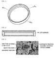
FIG. 1 is a perspective view illustrating a valve seat according to an exemplary embodiment of the present disclosure. -
FIG. 2 is a reference view for describing Experimental Example 1 of the present disclosure. -
FIG. 3 is an image in which the cut surface of the valve seat according to Example 1 of the present disclosure is analyzed. -
FIG. 4 is a reference view for describing Experimental Example 4 of the present disclosure. - Hereinafter, the present disclosure will be described.
- The valve seat of the present disclosure includes predetermined ranges of carbon, silicon, manganese, sulfur, chromium, molybdenum, nickel, tungsten, vanadium, and cobalt, and thus has excellent physical properties such as heat resistance and wear resistance, and this will be described in detail as follows.
- The valve seat of the present disclosure includes 0.8 to 1.7 wt% of carbon (C) based on the total weight. When the content of carbon is less than 0.8 wt%, the formation of the carbide structure in the structure of the valve seat deteriorates, and when the content of carbon exceeds 1.7 wt%, the ferrite structure remains in the structure of the valve seat, so that wear resistance of the valve seat may deteriorate. Therefore, it is preferred that carbon is included in the aforementioned range.
- The valve seat of the present disclosure includes 0.5 to 1.5 wt% of silicon (Si) based on the total weight. When the content of silicon is less than 0.5 wt%, production of a silicide produced by combining molybdenum (Mo) and cobalt (Co) deteriorates, so that wear resistance of the valve seat may deteriorate, and when the content of silicon exceeds 1.5 wt%, compressibility and sinterability may deteriorate when the valve seat is manufactured. Therefore, it is preferred that silicon is included in the aforementioned range.
- The valve seat of the present disclosure includes 0.5 to 1.5 wt% of manganese (Mn) based on the total weight. When the content of manganese is less than 0.5 wt%, processability of the valve seat may deteriorate, and when the content of manganese exceeds 1.5 wt%, compressibility and sinterability may deteriorate when the valve seat is manufactured. Therefore, it is preferred that manganese is included in the aforementioned range.
- The valve seat of the present disclosure includes 0.01 to 1.0 wt% of sulfur (S) based on the total weight. When the content of sulfur is less than 0.01 wt%, production of a material combined to manganese deteriorates, and when the content of sulfur exceeds 1.0 wt%, the carbide structure is excessively formed in the structure of the valve seat, so that processability may deteriorate when the valve seat is manufactured. Therefore, it is preferred that sulfur is included in the aforementioned range.
- The valve seat of the present disclosure includes 2.0 to 6.0 wt% of chromium (Cr) based on the total weight. When the content of chromium is less than 2.0 wt%, formation of the carbide structure in the structure of the valve seat deteriorates, so that wear resistance of the valve seat may deteriorate, and when the content of chromium exceeds 6.0 wt%, compressibility and sinterability deteriorate when the valve seat is manufactured, and wear resistance becomes excessively high, so that a degree that the valve, which is a counterpart material, is damaged may be increased. Therefore, it is preferred that chromium is included in the aforementioned range.
- The valve seat of the present disclosure includes 7.0 to 16.0 wt% of molybdenum (Mo) based on the total weight. When the content of molybdenum is less than 7.0 wt%, production of the silicide to which cobalt and molybdenum are combined deteriorates, so that wear resistance of the valve seat may deteriorate, and when the content of molybdenum exceeds 16.0 wt%, compressibility may deteriorate when the valve seat is manufactured. Therefore, it is preferred that molybdenum is included in the aforementioned range.
- The valve seat of the present disclosure includes 2.0 to 8.0 wt% of nickel (Ni) based on the total weight. When the content of nickel is less than 2.0 wt%, formation of the austenite structure in the structure of the valve seat deteriorates, so that wear resistance and heat resistance of the valve seat may deteriorate, and when the content of nickel exceeds 8.0 wt%, toughness of the valve seat becomes excessively high, and formation of the bainite structure deteriorates, so that wear resistance of the valve seat may deteriorate. Therefore, it is preferred that nickel is included in the aforementioned range.
- The valve seat of the present disclosure includes 0.01 to 3.0 wt% of tungsten (W) based on the total weight. When the content of tungsten is less than 0.01 wt%, formation of the carbide structure in the structure of the valve seat deteriorates, so that wear resistance of the valve seat may deteriorate, and when the content of tungsten exceeds 3.0 wt%, wear resistance of the valve seat becomes excessively high, so that a degree that the valve, which is a counterpart material, is damaged may be increased. Therefore, it is preferred that tungsten is included in the aforementioned range.
- The valve seat of the present disclosure includes 0.01 to 1.0 wt% of vanadium (V) based on the total weight. When the content of vanadium is less than 0.01 wt%, formation of the carbide structure in the structure of the valve seat deteriorates, so that wear resistance of the valve seat may deteriorate, and when the content of vanadium exceeds 1.0 wt%, compressibility and sinterability may deteriorate when the valve seat is manufactured. Therefore, it is preferred that vanadium is included in the aforementioned range.
- The valve seat of the present disclosure includes 14.0 to 25.0 wt% of cobalt (Co) based on the total weight. When the content of cobalt is less than 14.0 wt%, production of the silicide to which cobalt and molybdenum are combined deteriorates, so that wear resistance and heat resistance of the valve seat may deteriorate, and when the content of cobalt exceeds 25.0 wt%, compressibility and sinterability may deteriorate when the valve seat is manufactured. Therefore, it is preferred that cobalt is included in the aforementioned range.
- The valve seat of the present disclosure includes the balance of iron (Fe) and impurities (for example, phosphorus (P), sulfur (S), and the like) in addition to the aforementioned components.
- For the valve seat of the present disclosure, it is preferred that a bainite structure, a structure including a silicide to which cobalt (Co) and molybdenum (Mo) are combined, a martensite structure including chromium composite carbide, and an austenite structure co-exist in the structure of the valve seat. This is because it is possible to provide a valve seat in which wear resistance and heat resistance are excellent, and a degree that that the valve, which is a counterpart material, is damaged is minimized when the aforementioned structures co-exist.
- That is, the martensite structure including chromium composite carbide improves wear resistance of the valve seat, but when the structure is present alone, wear resistance of the valve seat becomes excessively high, so that a degree that the valve, which is a counterpart material, is damaged is increased. However, since the bainite structure, which increases wear resistance of the valve seat while less damaging the valve that is a counterpart material, and the austenite structure, which secures toughness of the valve seat, co-exist along with the martensite structure in the valve seat of the present disclosure, it is possible to minimize a degree that the valve, which is a counterpart material, is damaged while wear resistance is excellent.
- Further, as a structure including a silicide to which cobalt (Co) and molybdenum (Mo) are combined exists in the structure of the valve seat of the present disclosure, combining properties between the structures are improved, so that the valve seat of the present disclosure also has excellent heat resistance.
- Herein, in consideration of wear resistance of the valve seat and a degree that the valve, which is a counterpart material, is damaged, it is preferred that the bainite structure present in the structure of the valve seat of the present disclosure is present in an amount of 2 to 12 vol% based on the total 100 vol% of the valve seat. Specifically, the volume of the bainite structure may be calculated by the following method, and in this case, the ratio of the calculated volume to the total volume of the valve seat is 2 to 12 vol%.
- That is, at each point of A1, A2, and A3 in the valve seat, the valve seat is cut in a direction vertical to the ground surface, and then the area of the bainite structure found at each cut surface is measured. Herein, the area of the bainite structure may be measured through an image analysis of the cut surface. Thereafter, the volume (V) of the bainite structure may be calculated by the following equation.

- When a degree that the bainite structure occupies in the structure of the valve seat is converted into vol% as described above, the degree is preferably 2 to 12 vol%, and when a degree that the bainite structure occupies at the cut surface produced by cutting the valve seat is converted into area%, the degree is preferably 2 to 12% of the area of the cut surface.
- Meanwhile, the valve seat of the present disclosure may further include copper (Cu) or a copper alloy (for example, Cu-Zn, Cu-Co, Cu-Fe-Mn, Cu-Fe-Mn-Zn, and the like) infiltrated into pores in the structure in order to increase combining properties of the structure. Herein, the content of copper (Cu) or a copper alloy present in the structure of the valve seat is not particularly limited, but in consideration of processability of the valve seat, the content is preferably 1.0 to 25.0 wt% based on the total weight of the valve seat regardless of the chemical composition of the valve seat of the present disclosure.
- Furthermore, an iron-based sintered material may be further combined to the valve seat of the present disclosure in order to reduce the costs. That is, the valve seat of the present disclosure may have a dual-layer structure in which a part, which is closely adhered to a valve face (a part which is contacted with the valve), is composed of the component and composition described above and a part, which is not closely adhered to the valve face (a part which is not contacted with the valve), is composed of an iron-based sintered material. In this case, the component and composition of the iron-based sintered material are not particularly limited, but 0.1 to 1.5 wt% of carbon (C) and 0.1 to 25 wt% of copper (Cu) are included based on the total weight of the iron-based sintered material, and the balance may be composed of iron (Fe) and impurities.
- The present disclosure provides an engine including the valve seat described above. The kind of engine of the present disclosure is not particularly limited, but the engine may be a gas or diesel engine.
- A valve seat having the shape as in
FIG. 1 was molded by selecting the powder of each component through a powder metallurgical method, and then mixing and pressing the powder. Thereafter, the valve seat having the composition in the following Table 1 was each manufactured by sinteringvalve seat in a sintering furnace, and subjected the valve seat to post-processing (heat treatment). In this case, when the molded valve seat was sintered, a process of infiltrating copper (Cu) was added to Examples 6 to 9. Meanwhile, the composition of each valve seat manufactured was confirmed by an inductively-coupled plasma-mass spectrometer.[Table 1] Classification Chemical Component (wt%) C Si Mn S Cr Mo Ni Cu Pb W V Co Fe / Impurities Example 1 1.2 1.0 1.0 0.5 3.6 11 4.4 - - 1.4 0.4 21 Bal. Example 2 1.2 1.0 1.0 0.6 4.3 12 4.5 - - 1.4 0.4 19 Bal. Example 3 1.0 0.9 1.0 0.5 3.1 10 5.0 - - 0.6 0.2 21 Bal. Example 4 1.3 1.4 1.0 0.5 2.8 15 5.0 - - 0.9 0.3 18 Bal. Example 5 1.1 0.8 1.1 0.5 5.6 9 3.7 - - 2.0 0.6 25 Bal. Example 6 1.2 1.0 1.0 0.5 3.6 11 4.4 5 - 1.4 0.4 21 Bal. Example 7 1.2 1.0 1.0 0.5 3.6 11 4.4 15 - 1.4 0.4 21 Bal. Example 8 1.2 1.0 1.0 0.5 3.6 11 4.4 25 - 1.4 0.4 21 Bal. Example 9 1.2 1.0 1.0 0.5 3.6 11 4.4 30 - 1.4 0.4 21 Bal. - The valve seat having the composition in the following Table 2 was each manufactured by applying the method which is the same as in Example 1. In this case, a process of sintering the molded valve seat, and then impregnating lead (Pb) was added to Comparative Examples 5 and 9, and a process of infiltrating copper (Cu) when the molded valve seat was sintered was added to Comparative Examples 6, 8, 10, and 11. Meanwhile, the composition of each valve seat manufactured was confirmed by an inductively-coupled plasma-mass spectrometer.
[Table 2] Classification Chemical Component (wt%) C Si Mn S Cr Mo Ni Cu Pb W V Co Fe / Impurities Comparative Example 1 1.2 0.3 1.0 0.5 1.7 4 5.3 - - 1.4 0.4 6 Bal. Comparative Example 2 1.4 1.4 1.1 0.6 6.5 16.5 3.4 - - 2.6 0.8 25.5 Bal. Comparative Example 3 1.2 0.2 1.0 0.5 1.3 2.5 6.0 - - 1.4 0.4 3 Bal. Comparative Example 4 1.4 0.4 1.1 0.6 6.7 18 4.0 - - 2.7 0.9 29 Bal. Comparative Example 5 1.0 - - - 3.0 5 - - 20 6.0 3.0 - Bal. Comparative Example 6 1.0 - - - 3.0 5 - 20 - 6.0 3.0 - Bal. Comparative Example 7 0.6 1.0 1.0 0.5 5.5 13 0.5 0.3 - 3.5 1.0 20 Bal. Comparative Example 8 1.0 1.1 1.1 0.5 5.0 15 0.6 15 - 2.5 1.5 25 Bal. Comparative Example 9 0.8 1.5 - - 1.0 8 1.0 3 10 - - 10 Bal. Comparative Example 10 1.0 1.0 1.2 0.6 1.5 12 0.2 12 - - - 15 Bal. Comparative Example 11 0.5 0.8 2.0 1.4 2.0 13 - 12 - - - 16 Bal. - The valve seat manufactured in Example 1 was vertically cut (see
FIG. 2 ), the cut surface was polished and etched, and then observed by an optical microscope (200 times magnification was applied), and the results are shown inFIG. 3 . - Referring to
FIG. 3 , it can be confirmed that a bainite structure, a structure including a silicide to which cobalt (Co) and molybdenum (Mo) are combined, a martensite structure including chromium composite carbide, and an austenite structure co-exist in the structure of the valve seat. - The valve seat was cut in a direction vertical to the ground surface at A1, A2, and A3 points (see
FIG. 1 ) of each valve seat manufactured in Examples 1 to 5 and Comparative Examples 1 to 4, the cut surface was polished and etched, and then observed by an optical microscope to measure the area of the bainite structure found at each cut surface. - Thereafter, the volume (V) that the bainite structure occupies at the valve seat was calculated by the following equation, and the results are shown in the following Table 3.

[Table 3] Classification Ratio of Area that Bainite Structure Occupies at Cut Surface Ratio of Volume that Bainite Structure Occupies at Valve Seat A1% A2% A3% V% Example 1 6.6 7.9 9.2 7.9 Example 2 7.1 9.5 8.1 8.2 Example 3 7.7 6.2 7.7 7.2 Example 4 11.0 12.2 9.9 11.0 Example 5 7.2 6.3 6.2 6.6 Comparative Example 1 1.5 1.6 2.1 1.7 Comparative Example 2 13.5 12.2 13.8 13.2 Comparative Example 3 1.1 0.6 1.1 0.9 Comparative Example 4 14.2 14.7 15.1 14.7 - Referring to Table 3, it can be confirmed that in the valve seat of the present disclosure (Examples 1 to 5), the bainite structure is present in an amount of 2 to 12 vol% based on the total 100 vol% of the valve seat.
- Wear resistance was evaluated by applying the valve seats manufactured in Examples 1 to 5 and Comparative Examples 1 to 11 to a rig tester which simulated an engine valve train system, and the results are shown in the following Table 4. In this case, the test conditions and evaluation methods of the rig tester were as follows.
- Cam rotation speed: 1,100 rpm
- Temperature of valve seat: 150°C / 300°C
- Test time: 20 hours
- Evaluation method: the shape of a contact surface at which the valve and the valve seat were contacted was measured by a shape measuring machine, and then the maximum wear depth was analyzed at the measured shape.[Table 4] Classification Wear amount Rate of change in wear amount (%) 150°C 300°C Valve seat Valve Total Valve seat Valve Total Example 1 0.9 0.6 1.5 1.0 0.7 1.7 13.3 Example 2 1.4 0.5 1.9 1.7 0.5 2.2 15.8 Example 3 1.8 0.5 2.3 2.1 0.6 2.7 17.4 Example 4 1.5 0.4 1.9 1.6 0.5 2.1 10.5 Example 5 1.3 0.7 2.0 1.4 0.8 2.2 10.0 Example 6 1.0 0.6 1.6 1.1 0.7 1.8 12.5 Example 7 1.2 0.7 1.9 1.3 0.9 2.2 15.8 Example 8 1.4 0.9 2.3 1.6 1.1 2.7 17.4 Example 9 1.7 1.2 2.9 2.0 1.5 3.5 19.9 Comparative Example 1 2.2 0.7 2.9 2.8 0.8 3.6 24.1 Comparative Example 2 2.0 1.0 3.0 2.3 1.3 3.6 20.0 Comparative Example 3 2.2 0.7 2.9 3.0 0.8 3.8 31.0 Comparative Example 4 2.1 0.9 3.0 3.0 0.7 3.7 23.3 Comparative Example 5 2.0 0.7 2.7 2.7 1.2 3.9 44.4 Comparative Example 6 1.8 1.0 2.8 2.6 1.1 3.7 32.1 Comparative Example 7 4.0 1.1 5.1 4.8 1.7 6.5 27.5 Comparative Example 8 2.1 0.9 3.0 2.7 1.1 3.8 26.7 Comparative Example 9 2.2 1.1 3.3 3.7 1.3 5.0 51.5 Comparative Example 10 3.0 1.0 4.0 4.3 1.2 5.5 37.5 Comparative Example 11 3.1 0.8 3.9 4.0 1.2 5.2 33.3 - Referring to Table 4, it can be confirmed that the valve seats (Examples 1 to 9) of the present disclosure have excellent wear resistance. Further, it can be confirmed that the rate of change in wear amount is low even though the temperature was increased from 150°C to 300°C, which supports that the valve seat of the present disclosure has excellent heat resistance.
- The post-processability was evaluated by the following method when the valve seats in Examples 1 and 6 to 9 were manufactured, and the results are shown in
FIG. 4 . - Evaluation method: the molded valve seat was sintered, the depth of cut according to the post-processing was measured, and then the relative amount was calculated by defining the depth of cut in Example 6 as 1.
- Referring to
FIG. 4 , it can be confirmed that as the content of copper (Cu) infiltrated in Example 9 is higher than those in Examples 1 and 6 to 8, the cutting amount is increased when the post-processing is performed. This supports that it is preferred that the content of copper (Cu) infiltrated does not exceed 25 wt% in consideration of post-processability.
Claims (7)
- A valve seat comprising 0.8 to 1.7 wt% of carbon (C), 0.5 to 1.5 wt% of silicon (Si), 0.5 to 1.5 wt% of manganese (Mn), 0.01 to 1.0 wt% of sulfur (S), 2.0 to 6.0 wt% of chromium (Cr), 7.0 to 16.0 wt% of molybdenum (Mo), 2.0 to 8.0 wt% of nickel (Ni), 0.01 to 3.0 wt% of tungsten (W), 0.01 to 1.0 wt% of vanadium (V), 14.0 to 25.0 wt% of cobalt (Co), and a balance of iron and impurities.
- The valve seat of claim 1, wherein the valve seat comprises a bainite structure, a structure comprising a silicide to which cobalt (Co) and molybdenum (Mo) are combined, a martensite structure comprising chromium composite carbide, and an austenite structure in the structure of the valve seat.
- The valve seat of claim 1, wherein a bainite structure is present in an amount of 2 to 12 vol% based on a total 100 vol% of the valve seat.
- The valve seat of claim 1, wherein a ratio of an area that a bainite structure occupies at the cut surface formed by cutting the valve seat is 2 to 12% based on the area of the cut surface.
- The valve seat of claim 1, wherein copper (Cu) or a copper alloy is infiltrated into pores in the structure.
- The valve seat of claim 1, wherein an iron-based sintered material is further combined to the valve seat.
- An engine comprising the valve seat of any one of claims 1 to 6.
Applications Claiming Priority (1)
| Application Number | Priority Date | Filing Date | Title |
|---|---|---|---|
| KR1020140097222A KR102199856B1 (en) | 2014-07-30 | 2014-07-30 | A valve seat |
Publications (2)
| Publication Number | Publication Date |
|---|---|
| EP2980234A1 true EP2980234A1 (en) | 2016-02-03 |
| EP2980234B1 EP2980234B1 (en) | 2019-05-01 |
Family
ID=54010832
Family Applications (1)
| Application Number | Title | Priority Date | Filing Date |
|---|---|---|---|
| EP15179135.7A Active EP2980234B1 (en) | 2014-07-30 | 2015-07-30 | Valve seat |
Country Status (3)
| Country | Link |
|---|---|
| EP (1) | EP2980234B1 (en) |
| KR (1) | KR102199856B1 (en) |
| CN (1) | CN105316600B (en) |
Cited By (1)
| Publication number | Priority date | Publication date | Assignee | Title |
|---|---|---|---|---|
| DE102017102544A1 (en) | 2017-02-09 | 2018-08-09 | Man Diesel & Turbo Se | Valve seat ring of a gas exchange valve, gas exchange valve and method of manufacturing the valve seat ring |
Families Citing this family (1)
| Publication number | Priority date | Publication date | Assignee | Title |
|---|---|---|---|---|
| JP6929313B2 (en) * | 2018-09-03 | 2021-09-01 | ユソン エンタープライズ カンパニー,リミテッド | Iron-based sintered alloy for high-temperature wear resistance |
Citations (3)
| Publication number | Priority date | Publication date | Assignee | Title |
|---|---|---|---|---|
| US20050193861A1 (en) * | 2004-03-03 | 2005-09-08 | Nippon Piston Ring Co., Ltd. | Iron-based sintered alloy material for valve seat |
| US20110023808A1 (en) * | 2008-03-31 | 2011-02-03 | Nippon Piston Ring Co., Ltd. | Iron-based sintered alloy for valve seat, and valve seat for internal combustion engine |
| EP2927333A1 (en) * | 2014-03-31 | 2015-10-07 | Nippon Piston Ring Co., Ltd. | Iron-base sintered alloy material for valve seat insert and method for manufacturing the same |
Family Cites Families (6)
| Publication number | Priority date | Publication date | Assignee | Title |
|---|---|---|---|---|
| KR950014352B1 (en) | 1993-11-02 | 1995-11-25 | 대우중공업주식회사 | Process for making sintering alloy of valve sheet and article made thereby |
| JP3447030B2 (en) * | 1996-01-19 | 2003-09-16 | 日立粉末冶金株式会社 | Wear resistant sintered alloy and method for producing the same |
| JP2002285293A (en) * | 2001-03-27 | 2002-10-03 | Hitachi Powdered Metals Co Ltd | Valve seat material for high load engine and production method therefor |
| JP3786267B2 (en) * | 2002-10-02 | 2006-06-14 | 三菱マテリアルPmg株式会社 | Method for producing a valve seat made of an Fe-based sintered alloy that exhibits excellent wear resistance under high surface pressure application conditions |
| JP3926320B2 (en) * | 2003-01-10 | 2007-06-06 | 日本ピストンリング株式会社 | Iron-based sintered alloy valve seat and method for manufacturing the same |
| KR101438602B1 (en) * | 2012-04-02 | 2014-09-05 | 현대자동차 주식회사 | Sintered alloy for valve seat and manufacturing method of exhaust valve seat using the same |
-
2014
- 2014-07-30 KR KR1020140097222A patent/KR102199856B1/en active Active
-
2015
- 2015-07-29 CN CN201510454867.9A patent/CN105316600B/en active Active
- 2015-07-30 EP EP15179135.7A patent/EP2980234B1/en active Active
Patent Citations (3)
| Publication number | Priority date | Publication date | Assignee | Title |
|---|---|---|---|---|
| US20050193861A1 (en) * | 2004-03-03 | 2005-09-08 | Nippon Piston Ring Co., Ltd. | Iron-based sintered alloy material for valve seat |
| US20110023808A1 (en) * | 2008-03-31 | 2011-02-03 | Nippon Piston Ring Co., Ltd. | Iron-based sintered alloy for valve seat, and valve seat for internal combustion engine |
| EP2927333A1 (en) * | 2014-03-31 | 2015-10-07 | Nippon Piston Ring Co., Ltd. | Iron-base sintered alloy material for valve seat insert and method for manufacturing the same |
Cited By (1)
| Publication number | Priority date | Publication date | Assignee | Title |
|---|---|---|---|---|
| DE102017102544A1 (en) | 2017-02-09 | 2018-08-09 | Man Diesel & Turbo Se | Valve seat ring of a gas exchange valve, gas exchange valve and method of manufacturing the valve seat ring |
Also Published As
| Publication number | Publication date |
|---|---|
| KR102199856B1 (en) | 2021-01-11 |
| EP2980234B1 (en) | 2019-05-01 |
| CN105316600A (en) | 2016-02-10 |
| CN105316600B (en) | 2017-07-21 |
| KR20160015449A (en) | 2016-02-15 |
Similar Documents
| Publication | Publication Date | Title |
|---|---|---|
| CN105431256B (en) | Iron-based alloys and methods of making and using same | |
| US10605374B2 (en) | Valve seat insert excellent in wear resistance made of iron-base sintered alloy for internal combustion engines, and assembly of valve seat insert and valve | |
| US8733313B2 (en) | Iron-based sintered alloy for valve seat, and valve seat for internal combustion engine | |
| EP3047041B1 (en) | Iron-based alloys, methods of making them and use thereof | |
| TWI509085B (en) | Nitrogen containing, low nickel sintered stainless steel | |
| EP3276040B1 (en) | Nitrided or soft nitrided part with excellent wear resistance and pitting resistance | |
| EP2357262B1 (en) | Production method for a crankshaft | |
| JP6871361B2 (en) | Valve seat made of iron-based sintered alloy for internal combustion engine with excellent thermal conductivity | |
| JP2013213278A (en) | Sintered alloy for valve seat, method for manufacturing valve seat and valve seat utilizing the same | |
| EP2980234B1 (en) | Valve seat | |
| CN100475389C (en) | Sintered metal part and method for manufacturing same | |
| US20160052059A1 (en) | Compact for producing a sintered alloy, a wear-resistant iron-based sintered alloy, and a method for producing the same | |
| CN104907554A (en) | Powder material for powder metallurgy, preparation method thereof and application thereof | |
| JP6788817B2 (en) | Manufacturing method of vacuum carburized nitrided parts | |
| JP2012036418A (en) | High-strength spring and method for manufacturing the same | |
| JP2019026881A (en) | Steel member | |
| JP6378717B2 (en) | Iron-based sintered alloy and method for producing the same | |
| JP2001294970A (en) | Wear resistant sintered alloy for valve seat and its producing method | |
| JPS63109142A (en) | Ferrous sintered alloy combining heat resistance with wear resistance | |
| JP2002180215A (en) | Composite magnetic member having excellent low temperature magnetic stability and its production method | |
| EP2474637B1 (en) | Sintered material for valve guides and production method therefor | |
| EP3899077B1 (en) | Cemented carbide for high demand applications, and method of manufacturing thereof | |
| JP4188970B2 (en) | Cam lobe material, camshaft using the same, and method of manufacturing cam lobe material | |
| JP2705376B2 (en) | Valve seat made of Fe-based sintered alloy with high strength and toughness | |
| EP4026629A1 (en) | Iron-based pre-alloyed powder for powder metallurgy, diffusion-bonded powder for powder metallurgy, iron-based alloy powder for powder metallurgy, and sinter-forged member |
Legal Events
| Date | Code | Title | Description |
|---|---|---|---|
| PUAI | Public reference made under article 153(3) epc to a published international application that has entered the european phase |
Free format text: ORIGINAL CODE: 0009012 |
|
| AK | Designated contracting states |
Kind code of ref document: A1 Designated state(s): AL AT BE BG CH CY CZ DE DK EE ES FI FR GB GR HR HU IE IS IT LI LT LU LV MC MK MT NL NO PL PT RO RS SE SI SK SM TR |
|
| AX | Request for extension of the european patent |
Extension state: BA ME |
|
| 17P | Request for examination filed |
Effective date: 20160801 |
|
| RBV | Designated contracting states (corrected) |
Designated state(s): AL AT BE BG CH CY CZ DE DK EE ES FI FR GB GR HR HU IE IS IT LI LT LU LV MC MK MT NL NO PL PT RO RS SE SI SK SM TR |
|
| R17P | Request for examination filed (corrected) |
Effective date: 20160801 |
|
| GRAP | Despatch of communication of intention to grant a patent |
Free format text: ORIGINAL CODE: EPIDOSNIGR1 |
|
| STAA | Information on the status of an ep patent application or granted ep patent |
Free format text: STATUS: GRANT OF PATENT IS INTENDED |
|
| INTG | Intention to grant announced |
Effective date: 20181114 |
|
| GRAS | Grant fee paid |
Free format text: ORIGINAL CODE: EPIDOSNIGR3 |
|
| GRAA | (expected) grant |
Free format text: ORIGINAL CODE: 0009210 |
|
| STAA | Information on the status of an ep patent application or granted ep patent |
Free format text: STATUS: THE PATENT HAS BEEN GRANTED |
|
| AK | Designated contracting states |
Kind code of ref document: B1 Designated state(s): AL AT BE BG CH CY CZ DE DK EE ES FI FR GB GR HR HU IE IS IT LI LT LU LV MC MK MT NL NO PL PT RO RS SE SI SK SM TR |
|
| REG | Reference to a national code |
Ref country code: GB Ref legal event code: FG4D |
|
| REG | Reference to a national code |
Ref country code: CH Ref legal event code: EP Ref country code: AT Ref legal event code: REF Ref document number: 1126957 Country of ref document: AT Kind code of ref document: T Effective date: 20190515 |
|
| REG | Reference to a national code |
Ref country code: DE Ref legal event code: R096 Ref document number: 602015029185 Country of ref document: DE |
|
| REG | Reference to a national code |
Ref country code: IE Ref legal event code: FG4D |
|
| REG | Reference to a national code |
Ref country code: SE Ref legal event code: TRGR |
|
| REG | Reference to a national code |
Ref country code: NL Ref legal event code: MP Effective date: 20190501 |
|
| REG | Reference to a national code |
Ref country code: LT Ref legal event code: MG4D |
|
| PG25 | Lapsed in a contracting state [announced via postgrant information from national office to epo] |
Ref country code: HR Free format text: LAPSE BECAUSE OF FAILURE TO SUBMIT A TRANSLATION OF THE DESCRIPTION OR TO PAY THE FEE WITHIN THE PRESCRIBED TIME-LIMIT Effective date: 20190501 Ref country code: NO Free format text: LAPSE BECAUSE OF FAILURE TO SUBMIT A TRANSLATION OF THE DESCRIPTION OR TO PAY THE FEE WITHIN THE PRESCRIBED TIME-LIMIT Effective date: 20190801 Ref country code: NL Free format text: LAPSE BECAUSE OF FAILURE TO SUBMIT A TRANSLATION OF THE DESCRIPTION OR TO PAY THE FEE WITHIN THE PRESCRIBED TIME-LIMIT Effective date: 20190501 Ref country code: ES Free format text: LAPSE BECAUSE OF FAILURE TO SUBMIT A TRANSLATION OF THE DESCRIPTION OR TO PAY THE FEE WITHIN THE PRESCRIBED TIME-LIMIT Effective date: 20190501 Ref country code: LT Free format text: LAPSE BECAUSE OF FAILURE TO SUBMIT A TRANSLATION OF THE DESCRIPTION OR TO PAY THE FEE WITHIN THE PRESCRIBED TIME-LIMIT Effective date: 20190501 Ref country code: AL Free format text: LAPSE BECAUSE OF FAILURE TO SUBMIT A TRANSLATION OF THE DESCRIPTION OR TO PAY THE FEE WITHIN THE PRESCRIBED TIME-LIMIT Effective date: 20190501 Ref country code: PT Free format text: LAPSE BECAUSE OF FAILURE TO SUBMIT A TRANSLATION OF THE DESCRIPTION OR TO PAY THE FEE WITHIN THE PRESCRIBED TIME-LIMIT Effective date: 20190901 Ref country code: FI Free format text: LAPSE BECAUSE OF FAILURE TO SUBMIT A TRANSLATION OF THE DESCRIPTION OR TO PAY THE FEE WITHIN THE PRESCRIBED TIME-LIMIT Effective date: 20190501 |
|
| PG25 | Lapsed in a contracting state [announced via postgrant information from national office to epo] |
Ref country code: BG Free format text: LAPSE BECAUSE OF FAILURE TO SUBMIT A TRANSLATION OF THE DESCRIPTION OR TO PAY THE FEE WITHIN THE PRESCRIBED TIME-LIMIT Effective date: 20190801 Ref country code: GR Free format text: LAPSE BECAUSE OF FAILURE TO SUBMIT A TRANSLATION OF THE DESCRIPTION OR TO PAY THE FEE WITHIN THE PRESCRIBED TIME-LIMIT Effective date: 20190802 Ref country code: LV Free format text: LAPSE BECAUSE OF FAILURE TO SUBMIT A TRANSLATION OF THE DESCRIPTION OR TO PAY THE FEE WITHIN THE PRESCRIBED TIME-LIMIT Effective date: 20190501 Ref country code: RS Free format text: LAPSE BECAUSE OF FAILURE TO SUBMIT A TRANSLATION OF THE DESCRIPTION OR TO PAY THE FEE WITHIN THE PRESCRIBED TIME-LIMIT Effective date: 20190501 |
|
| REG | Reference to a national code |
Ref country code: AT Ref legal event code: MK05 Ref document number: 1126957 Country of ref document: AT Kind code of ref document: T Effective date: 20190501 |
|
| PG25 | Lapsed in a contracting state [announced via postgrant information from national office to epo] |
Ref country code: IS Free format text: LAPSE BECAUSE OF FAILURE TO SUBMIT A TRANSLATION OF THE DESCRIPTION OR TO PAY THE FEE WITHIN THE PRESCRIBED TIME-LIMIT Effective date: 20190901 |
|
| PG25 | Lapsed in a contracting state [announced via postgrant information from national office to epo] |
Ref country code: SK Free format text: LAPSE BECAUSE OF FAILURE TO SUBMIT A TRANSLATION OF THE DESCRIPTION OR TO PAY THE FEE WITHIN THE PRESCRIBED TIME-LIMIT Effective date: 20190501 Ref country code: AT Free format text: LAPSE BECAUSE OF FAILURE TO SUBMIT A TRANSLATION OF THE DESCRIPTION OR TO PAY THE FEE WITHIN THE PRESCRIBED TIME-LIMIT Effective date: 20190501 Ref country code: DK Free format text: LAPSE BECAUSE OF FAILURE TO SUBMIT A TRANSLATION OF THE DESCRIPTION OR TO PAY THE FEE WITHIN THE PRESCRIBED TIME-LIMIT Effective date: 20190501 Ref country code: CZ Free format text: LAPSE BECAUSE OF FAILURE TO SUBMIT A TRANSLATION OF THE DESCRIPTION OR TO PAY THE FEE WITHIN THE PRESCRIBED TIME-LIMIT Effective date: 20190501 Ref country code: RO Free format text: LAPSE BECAUSE OF FAILURE TO SUBMIT A TRANSLATION OF THE DESCRIPTION OR TO PAY THE FEE WITHIN THE PRESCRIBED TIME-LIMIT Effective date: 20190501 Ref country code: EE Free format text: LAPSE BECAUSE OF FAILURE TO SUBMIT A TRANSLATION OF THE DESCRIPTION OR TO PAY THE FEE WITHIN THE PRESCRIBED TIME-LIMIT Effective date: 20190501 |
|
| REG | Reference to a national code |
Ref country code: DE Ref legal event code: R097 Ref document number: 602015029185 Country of ref document: DE |
|
| PG25 | Lapsed in a contracting state [announced via postgrant information from national office to epo] |
Ref country code: SM Free format text: LAPSE BECAUSE OF FAILURE TO SUBMIT A TRANSLATION OF THE DESCRIPTION OR TO PAY THE FEE WITHIN THE PRESCRIBED TIME-LIMIT Effective date: 20190501 Ref country code: MC Free format text: LAPSE BECAUSE OF FAILURE TO SUBMIT A TRANSLATION OF THE DESCRIPTION OR TO PAY THE FEE WITHIN THE PRESCRIBED TIME-LIMIT Effective date: 20190501 |
|
| REG | Reference to a national code |
Ref country code: CH Ref legal event code: PL |
|
| PLBE | No opposition filed within time limit |
Free format text: ORIGINAL CODE: 0009261 |
|
| STAA | Information on the status of an ep patent application or granted ep patent |
Free format text: STATUS: NO OPPOSITION FILED WITHIN TIME LIMIT |
|
| PG25 | Lapsed in a contracting state [announced via postgrant information from national office to epo] |
Ref country code: TR Free format text: LAPSE BECAUSE OF FAILURE TO SUBMIT A TRANSLATION OF THE DESCRIPTION OR TO PAY THE FEE WITHIN THE PRESCRIBED TIME-LIMIT Effective date: 20190501 |
|
| 26N | No opposition filed |
Effective date: 20200204 |
|
| REG | Reference to a national code |
Ref country code: BE Ref legal event code: MM Effective date: 20190731 |
|
| PG25 | Lapsed in a contracting state [announced via postgrant information from national office to epo] |
Ref country code: PL Free format text: LAPSE BECAUSE OF FAILURE TO SUBMIT A TRANSLATION OF THE DESCRIPTION OR TO PAY THE FEE WITHIN THE PRESCRIBED TIME-LIMIT Effective date: 20190501 |
|
| PG25 | Lapsed in a contracting state [announced via postgrant information from national office to epo] |
Ref country code: BE Free format text: LAPSE BECAUSE OF NON-PAYMENT OF DUE FEES Effective date: 20190731 Ref country code: CH Free format text: LAPSE BECAUSE OF NON-PAYMENT OF DUE FEES Effective date: 20190731 Ref country code: LU Free format text: LAPSE BECAUSE OF NON-PAYMENT OF DUE FEES Effective date: 20190730 Ref country code: LI Free format text: LAPSE BECAUSE OF NON-PAYMENT OF DUE FEES Effective date: 20190731 Ref country code: SI Free format text: LAPSE BECAUSE OF FAILURE TO SUBMIT A TRANSLATION OF THE DESCRIPTION OR TO PAY THE FEE WITHIN THE PRESCRIBED TIME-LIMIT Effective date: 20190501 |
|
| PG25 | Lapsed in a contracting state [announced via postgrant information from national office to epo] |
Ref country code: IE Free format text: LAPSE BECAUSE OF NON-PAYMENT OF DUE FEES Effective date: 20190730 |
|
| PG25 | Lapsed in a contracting state [announced via postgrant information from national office to epo] |
Ref country code: CY Free format text: LAPSE BECAUSE OF FAILURE TO SUBMIT A TRANSLATION OF THE DESCRIPTION OR TO PAY THE FEE WITHIN THE PRESCRIBED TIME-LIMIT Effective date: 20190501 |
|
| PG25 | Lapsed in a contracting state [announced via postgrant information from national office to epo] |
Ref country code: HU Free format text: LAPSE BECAUSE OF FAILURE TO SUBMIT A TRANSLATION OF THE DESCRIPTION OR TO PAY THE FEE WITHIN THE PRESCRIBED TIME-LIMIT; INVALID AB INITIO Effective date: 20150730 Ref country code: MT Free format text: LAPSE BECAUSE OF FAILURE TO SUBMIT A TRANSLATION OF THE DESCRIPTION OR TO PAY THE FEE WITHIN THE PRESCRIBED TIME-LIMIT Effective date: 20190501 |
|
| REG | Reference to a national code |
Ref country code: DE Ref legal event code: R081 Ref document number: 602015029185 Country of ref document: DE Owner name: HYUNDAI DOOSAN INFRACORE CO., LTD., KR Free format text: FORMER OWNER: DOOSAN INFRACORE CO., LTD., DONG-GU, INCHEON, KR Ref country code: DE Ref legal event code: R081 Ref document number: 602015029185 Country of ref document: DE Owner name: HD HYUNDAI INFRACORE CO., LTD., KR Free format text: FORMER OWNER: DOOSAN INFRACORE CO., LTD., DONG-GU, INCHEON, KR |
|
| PG25 | Lapsed in a contracting state [announced via postgrant information from national office to epo] |
Ref country code: MK Free format text: LAPSE BECAUSE OF FAILURE TO SUBMIT A TRANSLATION OF THE DESCRIPTION OR TO PAY THE FEE WITHIN THE PRESCRIBED TIME-LIMIT Effective date: 20190501 |
|
| REG | Reference to a national code |
Ref country code: DE Ref legal event code: R081 Ref document number: 602015029185 Country of ref document: DE Owner name: HD HYUNDAI INFRACORE CO., LTD., KR Free format text: FORMER OWNER: HYUNDAI DOOSAN INFRACORE CO., LTD., INCHEON, KR |
|
| PGFP | Annual fee paid to national office [announced via postgrant information from national office to epo] |
Ref country code: GB Payment date: 20250605 Year of fee payment: 11 |
|
| PGFP | Annual fee paid to national office [announced via postgrant information from national office to epo] |
Ref country code: FR Payment date: 20250610 Year of fee payment: 11 |
|
| PGFP | Annual fee paid to national office [announced via postgrant information from national office to epo] |
Ref country code: SE Payment date: 20250610 Year of fee payment: 11 |
|
| PGFP | Annual fee paid to national office [announced via postgrant information from national office to epo] |
Ref country code: DE Payment date: 20250604 Year of fee payment: 11 |
|
| PGFP | Annual fee paid to national office [announced via postgrant information from national office to epo] |
Ref country code: IT Payment date: 20250623 Year of fee payment: 11 |