EP2979806B1 - Widerstandspunktschweissverfahren - Google Patents
Widerstandspunktschweissverfahren Download PDFInfo
- Publication number
- EP2979806B1 EP2979806B1 EP14772698.8A EP14772698A EP2979806B1 EP 2979806 B1 EP2979806 B1 EP 2979806B1 EP 14772698 A EP14772698 A EP 14772698A EP 2979806 B1 EP2979806 B1 EP 2979806B1
- Authority
- EP
- European Patent Office
- Prior art keywords
- welding
- heat generated
- current
- amount
- time variation
- Prior art date
- Legal status (The legal status is an assumption and is not a legal conclusion. Google has not performed a legal analysis and makes no representation as to the accuracy of the status listed.)
- Active
Links
- 238000003466 welding Methods 0.000 title claims description 230
- 230000001186 cumulative effect Effects 0.000 claims description 49
- 238000012360 testing method Methods 0.000 claims description 45
- 239000000463 material Substances 0.000 claims description 42
- 230000003044 adaptive effect Effects 0.000 claims description 31
- 238000004364 calculation method Methods 0.000 claims description 5
- 238000003825 pressing Methods 0.000 claims description 3
- 229910052751 metal Inorganic materials 0.000 claims description 2
- 239000002184 metal Substances 0.000 claims description 2
- 229910000831 Steel Inorganic materials 0.000 description 17
- 239000010959 steel Substances 0.000 description 17
- 238000000034 method Methods 0.000 description 15
- 239000011248 coating agent Substances 0.000 description 8
- 238000000576 coating method Methods 0.000 description 8
- 230000000694 effects Effects 0.000 description 8
- 230000000052 comparative effect Effects 0.000 description 5
- 238000012544 monitoring process Methods 0.000 description 5
- 230000015572 biosynthetic process Effects 0.000 description 4
- 238000001514 detection method Methods 0.000 description 4
- 230000007423 decrease Effects 0.000 description 3
- 238000012546 transfer Methods 0.000 description 3
- 238000013459 approach Methods 0.000 description 2
- ZTXONRUJVYXVTJ-UHFFFAOYSA-N chromium copper Chemical compound [Cr][Cu][Cr] ZTXONRUJVYXVTJ-UHFFFAOYSA-N 0.000 description 2
- 239000004020 conductor Substances 0.000 description 2
- 238000004088 simulation Methods 0.000 description 2
- 229910001335 Galvanized steel Inorganic materials 0.000 description 1
- 229910001209 Low-carbon steel Inorganic materials 0.000 description 1
- 238000010586 diagram Methods 0.000 description 1
- 238000009826 distribution Methods 0.000 description 1
- 238000005530 etching Methods 0.000 description 1
- 238000002474 experimental method Methods 0.000 description 1
- 230000004927 fusion Effects 0.000 description 1
- 239000008397 galvanized steel Substances 0.000 description 1
- 238000004519 manufacturing process Methods 0.000 description 1
- 238000005259 measurement Methods 0.000 description 1
- 238000002844 melting Methods 0.000 description 1
- 230000008018 melting Effects 0.000 description 1
- OXNIZHLAWKMVMX-UHFFFAOYSA-N picric acid Chemical class OC1=C([N+]([O-])=O)C=C([N+]([O-])=O)C=C1[N+]([O-])=O OXNIZHLAWKMVMX-UHFFFAOYSA-N 0.000 description 1
- 238000005070 sampling Methods 0.000 description 1
Images


Classifications
-
- B—PERFORMING OPERATIONS; TRANSPORTING
- B23—MACHINE TOOLS; METAL-WORKING NOT OTHERWISE PROVIDED FOR
- B23K—SOLDERING OR UNSOLDERING; WELDING; CLADDING OR PLATING BY SOLDERING OR WELDING; CUTTING BY APPLYING HEAT LOCALLY, e.g. FLAME CUTTING; WORKING BY LASER BEAM
- B23K11/00—Resistance welding; Severing by resistance heating
- B23K11/10—Spot welding; Stitch welding
- B23K11/11—Spot welding
- B23K11/115—Spot welding by means of two electrodes placed opposite one another on both sides of the welded parts
-
- B—PERFORMING OPERATIONS; TRANSPORTING
- B23—MACHINE TOOLS; METAL-WORKING NOT OTHERWISE PROVIDED FOR
- B23K—SOLDERING OR UNSOLDERING; WELDING; CLADDING OR PLATING BY SOLDERING OR WELDING; CUTTING BY APPLYING HEAT LOCALLY, e.g. FLAME CUTTING; WORKING BY LASER BEAM
- B23K11/00—Resistance welding; Severing by resistance heating
- B23K11/24—Electric supply or control circuits therefor
- B23K11/25—Monitoring devices
- B23K11/252—Monitoring devices using digital means
- B23K11/255—Monitoring devices using digital means the measured parameter being a force
Definitions
- This disclosure relates to a resistance spot welding system for multistep current passage in which the current pattern has two or more steps.
- this disclosure attempts to form a suitable nugget by utilizing adaptive control welding in each step.
- Resistance spot welding which is a type of lap resistance welding, is typically used to join overlapping steel sheets.
- This welding method is a method to join two or more overlapping steel sheets by applying a high welding current for a short time between a pair of electrodes squeezing the steel sheets from above and below.
- a point-like weld is obtained using the resistance heat generated by passing the high-current welding current.
- Such a point-like weld is referred to as a nugget and is the portion where both of the overlapping steel sheets fuse and coagulate at a location of contact between the steel sheets when current is applied to the steel sheets.
- the steel sheets are joined in a point-like manner by this nugget.
- the nugget diameter is determined by welding conditions such as the welding current, welding time, electrode shape, electrode force, and the like. Therefore, to form an appropriate nugget diameter, the above welding conditions need to be set appropriately in accordance with the conditions of materials to be welded, such as the material properties, sheet thickness, number of sheets overlapped, and the like.
- a resistance welding device provided with a function (stepper function) to increase the welding current after welding a predetermined number of times, so as to compensate for the reduction in current density due to wear of the electrodes, has also been used conventionally.
- stepper function the above-described pattern for changing the welding current needs to be set appropriately in advance. Performing tests or the like, however, to derive a pattern for changing the welding current that corresponds to numerous welding conditions and conditions of materials to be welded is highly time-consuming and expensive.
- the state of progress of electrode wear also varies during actual work. Therefore, the predetermined pattern for changing the welding current cannot always be considered appropriate.
- JP H9-216071 A discloses a control unit of a resistance welder that obtains a set nugget by comparing an estimated temperature distribution of the weld with a target nugget and controlling output of the welder.
- JP H10-94883 A discloses a method of controlling welding conditions of a resistance welder to achieve good welding by detecting the welding current and the voltage between tips, performing a simulation of the weld by heat transfer calculation, and estimating the formation state of the nugget.
- JP H11-33743 A discloses the achievement of a good weld, regardless of the type of materials being welded or the wear state of the electrodes, with a welding system that first uses the sheet thickness of the materials being welded and the welding time to calculate the cumulative amount of heat generated per unit volume that allows for good welding of the materials being welded and then adjusts the welding current or voltage that yields the calculated amount of heat generated per unit volume and unit time.
- the resistance spot welding system recited in PTL 3 always allows for good welding regardless of the degree of electrode wear by controlling the cumulative amount of heat generated to be a target value.
- the set conditions of materials to be welded and the actual conditions of materials to be welded greatly differ, however, for example in cases such as when there is a disturbance nearby such as the aforementioned previously welded point, when the time variation pattern of the amount of heat generated changes greatly in a short period of time, or when welding hot-dip galvanized steel sheets with a large coating weight, then adaptive control cannot keep up, the necessary nugget diameter might not be obtained, or splashing may occur due to excessive heat input.
- the system further comprises:
- the materials to be welded are welded with constant current control in an ideal state (a state with no sheet gap, electrode core misalignment, or the like) to discover conditions for forming an appropriate nugget.
- This welding is treated as test welding, and the time variation of the instantaneous amount of heat generated during the welding is calculated and stored. Therefore, as long as regular resistance spot welding can be applied to the material, adaptive control-based resistance spot welding can be applied to any type of steel sheet upon the next welding.
- the stored time variation of the instantaneous amount of heat generated is divided into two or more steps, and the time variation of the instantaneous amount of heat generated for each step, as well as a cumulative amount of heat generated, are newly stored as target values.
- the designation of timing for this division into a plurality of steps may be made by input from an external source. Therefore, by monitoring parameters during welding such as the current, voltage between electrodes, resistance between electrodes, distance between electrodes, electrode force, and the like, it is possible for the test welding to be divided into a plurality of steps easily at an appropriate timing desired by the operator based on the results of monitoring.
- the electrode force state change detector measures the timing of when the electrode force during test welding reaches a designated value.
- test welding is performed before the actual welding, and from an electrical property between electrodes when forming an appropriate nugget, the time variation of the instantaneous amount of heat generated as well as the cumulative amount of heat generated are calculated and stored. Based on the time variation of the instantaneous amount of heat generated, a current pattern is divided into a plurality of steps in accordance with input from an external source, and the time variation of the instantaneous amount of heat generated and the cumulative amount of heat generated for each step are stored as target values.
- adaptive control welding is utilized to compensate for the difference during the remaining welding time in the step so as to match the cumulative amount of heat generated of the actual welding to the cumulative amount of heat generated that was calculated during the test welding.
- FIG. 1 illustrates the structure of our resistance spot welding system.
- reference numeral 1 indicates a resistance spot welding power source
- 2 indicates a control processor providing a control signal to the resistance spot welding power source
- 3 indicates a welding current detector that inputs a detected signal into the control processor 2.
- Reference numeral 4 indicates a secondary conductor that is connected to the output of the resistance spot welding power source 1 and is connected to electrodes 7 in order to pass current to the electrodes 7.
- Reference numeral 5 indicates a lower arm and 6 indicates a pressure cylinder, to which respective electrodes 7 are attached. The materials to be welded 8 are squeezed by the electrodes 7.
- a strain sensor 9 is attached to the lower arm 5.
- Reference numeral 10 indicates an electrode force input processor that acts as an electrode force state change detector connected to the strain sensor 9. The electrode force input processor 10 is configured to allow for measurement of the change in the electrode force during welding by digitizing, with an A/D converter, the strain detected by the strain sensor 9 and calculating the electrode force from the strain amount of the arm when pressure is being applied.
- Reference numeral 11 indicates inter-electrode voltage detection lines, attached to the electrodes 7, that enter the control processor 2.
- the control processor 2 can switch between a mode to perform test welding and a mode to perform actual welding.
- the instantaneous amount of heat generated is calculated from the current that is input from the welding current detector 3 and the voltage that is input from the inter-electrode voltage detection lines 11, and the time variation of the instantaneous amount of heat generated is stored.
- the stored time variation of the instantaneous amount of heat generated is divided into a plurality of steps at a timing that is input from an external input processor 12, and the time variation of the instantaneous amount of heat generated and a cumulative amount of heat generated are stored separately for each step as target values.
- the system is configured so that input to the external input processor 12 may be numeric input of the division timing from a user, and that the timing of when the electrode force during welding reaches a designated value is automatically determined in the electrode force input processor 10 from collected data and is input automatically as a numerical value.
- the designated electrode force is not limited to being one point. As necessary, the designated electrode force may be two points, three points, or more.
- the target of monitoring is not limited to the electrode force. As long as a change in a phenomenon during welding can be discerned, any of the following may be monitored: a change in distance between electrodes, a value from a servomotor encoder used in pressing, resistance, the amount of heat generated that is calculated from current, voltage, or other value by some sort of equation, or the like. Furthermore, monitoring a combination of a plurality of parameters to set many division timings is more effective, as doing so allows for adaptive control that is highly responsive to a change in a phenomenon during welding.
- a test on the same type of steel and thickness as the materials to be welded is performed by welding under a variety of conditions with constant current control in a state with no gap or diversion to a previously welded point.
- the welding conditions for obtaining a necessary nugget diameter i.e. the appropriate electrode force F, welding time T, and welding current I, are thus discovered.
- an inverter DC resistance spot welder is preferable as the welder, and chromium copper electrodes with DR-shaped tips may be advantageously adapted for use as the electrodes.
- the nugget diameter may be determined by a peel test or by cross-sectional observation at the nugget center (by etching with a saturated picric acid solution).
- the electrical property between electrodes refers to the resistance between electrodes or the voltage between electrodes.
- the current pattern is divided into two or more steps.
- adaptive control that is highly responsive to a change in a phenomenon during welding can be performed, yet a desired effect can be obtained with just two or three steps. Therefore, taking practicality into account, the cases of dividing into two and three steps are described.
- the time when the weld forms between steel sheets is preferably used as the dividing point. This is the point between the beginning of weld formation between the steel sheets and the subsequent process of nugget growth.
- the timing at which the weld begins to form between the steel sheets can be determined by observation through a peel test, or through cross-sectional observation of the weld, after welding by changing the welding time.
- the materials to be welded are coated steel sheets, three-step division that takes fusion of the coating into account is more preferable.
- the reason is that when coating is present, the effect of diversion is large, resulting in a large change in the phenomenon up until a stable current path forms directly below the electrodes. Since the melting point of the coating is lower than that of the steel sheets, the coating between the steel sheets first fuses after passage of current begins, and a portion of the fused coating is expelled from between the steel sheets due to the electrode force. The coating that is expelled at this time expands the current conducting area, thereby greatly reducing the resistance between electrodes during welding. Conversely, the specific resistance of the materials to be welded increases along with a rise in temperature.
- the specific resistance increases as the welding time lengthens, and after the decrease in resistance between electrodes due to the expanded current conducting area, an increase in the resistance between electrodes occurs due to the rise in temperature of the materials to be welded. Subsequently, the weld forms. Therefore, dividing the welding process into three steps, i.e. the step in which the coating fuses and the current conducting area expands suddenly, the step up until a stable current path (weld) forms between the electrodes due to subsequent passage of current, and the subsequent nugget formation step, and then performing, in each step, adaptive control welding to guarantee the cumulative amount of heat generated per unit volume allows for a stable current path to be formed by resistance spot welding of coated steel sheets, even if a previously welded point is located nearby. This approach also allows for stable nugget growth in the subsequent third step.
- Performing multistep adaptive control divided into multiple steps so as to correspond to a change in the welding state, as described above, allows for a nugget with the necessary diameter to be obtained stably even for a workpiece in which the effect of a disturbance is great.
- the time variation of the instantaneous amount of heat generated that is stored in the test welding is divided at the timing input from the external input processor 10, and the time variation of the instantaneous amount of heat generated and a cumulative amount of heat generated are stored for each step as target values.
- Another effective method is to monitor the resistance between electrodes, voltage between electrodes, distance between electrodes, electrode force, or the like during welding and determine the timing from the change in these factors.
- the case of using a change in electrode force during welding as an index of the timing for division into multiple steps is described.
- the change in electrode force during welding can be measured with the strain sensor 9 attached to the lower arm 5.
- the strain sensor 9 attached to the lower arm 5.
- the area near the weld undergoes thermal expansion due to the temperature rise in the weld.
- the gap between the clamping electrodes is expanded by force, and the substantial electrode force increases.
- the electrode force then exhibits a waveform pattern with a peak, after which the electrode force decreases due to the electrode sinking into the materials to be welded as a result of formation of the weld and softening of the materials. Therefore, the point in time indicating the peak can be considered the timing at which a stable current path is formed.
- the welding system may be configured so that during welding in the test welding mode, the timing for obtaining the maximum electrode force during welding is determined automatically by the electrode force input processor 10 from collected data, with the resulting numerical value being automatically input into the external input processor 12.
- This approach yields target values for instantaneous amount of heat generated and cumulative amount of heat generated effectively divided into multiple steps.
- the actual welding is started using, as a standard, a time variation curve of the instantaneous amount of heat generated that is obtained by the test welding, and in each of the steps, when the time variation amount of the instantaneous amount of heat generated follows the time variation curve that is the standard, welding is performed as is to completion.
- adaptive control welding is performed to control the current passage amount in response to the difference, thereby compensating during the remaining welding time in the step so that the cumulative amount of heat generated in the actual welding matches the cumulative amount of heat generated determined in advance in the test welding.
- PTL 3 discloses one example, which is used in this disclosure.
- the amount of heat generated per unit volume and the cumulative amount of heat generated per unit volume can be treated as target values.
- the cumulative amount of heat generated Q per unit volume is calculated with this method as follows.
- the total thickness of the two materials to be welded be t
- the electrical resistivity of the materials to be welded be r
- the voltage between electrodes be V
- the welding current be I
- the area of contact between the electrodes and the materials to be welded be S.
- the welding current passes through a columnar portion with a cross-sectional area S and thickness t, generating resistance heat.
- the amount of heat generated q per unit volume and unit time in this columnar portion is determined with Equation (1) below.
- the amount of heat generated q per unit volume and unit time can be calculated from the voltage between electrodes V, total thickness t of materials being welded, and electrical resistivity r of the materials being welded. Therefore, the amount of heat generated q is not affected by the area S of contact between the electrodes and the materials being welded.
- Equation (3) the amount of heat generated is calculated from the voltage between electrodes V, yet the amount of heat generated q may also be calculated from the current between electrodes 1. In this case as well, the area S of contact between the electrodes and the materials being welded need not be used.
- Examples of the disturbance referred to in this disclosure include the above-described presence of a previously welded point near the welding point or contact point between the materials to be welded, as well as wear of the electrodes or the like.
- test welding has been described as being performed in a state without disturbances such as previously welded points. Performing the test welding in a state with a previously welded point, however, poses no problem whatsoever, as doing so reduces the difference between the conditions of test welding and actual welding, thereby facilitating effective performance of adaptive control.
- Mild steel (thickness: 1.6 mm) was prepared as the materials to be welded.
- the welding current was passed with a two-step current passage method.
- Two sheets of the materials to be welded were overlapped and welded with constant current control in a state with no gap or diversion to a previously welded point.
- the welding conditions for obtaining a suitable nugget diameter were thus obtained.
- An inverter DC resistance spot welder was used as the welder, and chromium copper electrodes with 6 mm face diameter DR-shaped tips were used as the electrodes.
- an electrode force of 3.43 kN (350 kgf) and a welding time of 16 cyc (50 Hz (hereinafter, time units all refer to the number of cycles at 50 Hz)) were kept constant, and the welding current was changed to a variety of settings to determine the current at which a nugget diameter of 4 ⁇ t (t: sheet thickness) was obtained.
- FIG. 2(a) illustrates a weld cross-section when performing this test welding
- FIG. 2(b) illustrates the corresponding change over time of the welding current, electrical resistance, cumulative amount of heat generated, and electrode force.
- the timing for dividing the welding process into two steps was set to 4 cyc, which indicates the peak of the electrode force during the welding, and was input from the external input processor 12 into the control processor 2.
- 4 cyc indicates the peak of the electrode force during the welding
- 4 cyc to 16 cyc the time variation of the instantaneous amount of heat generated per unit volume and the cumulative amount of heat generated per unit volume were stored as target values for each step.
- the target cumulative amount of heat generated that was obtained in the test welding was 138 J for the first step and 167 J for the second step. Therefore, the final target cumulative amount of heat generated was 305 J.
- Multistep adaptive control resistance spot welding according to our system was performed with the above test welding as a standard, under the conditions of a previously welded point present near the welding point (distance between centers of points: 7.5 mm) and a large effect of diversion.
- resistance spot welding was performed using, as a standard, the time variation curve of the instantaneous amount of heat generated per unit volume obtained by test welding.
- FIG. 3(a) illustrates a weld cross-section at that time
- FIG. 3(b) illustrates the change over time of the welding current, electrical resistance, and cumulative amount of heat generated.
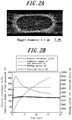
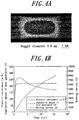
- resistance spot welding with constant current control (Comparative Example 1) and adaptive control welding with conventional one-step current passage were performed under the condition of a previously welded point present near the welding point (distance between centers of points: 7.5 mm).
- the constant current control welding was performed under the conditions of an electrode force of 3.43 kN (350 kgf), welding time of 16 cyc, and welding current of 6.2 kA.
- the adaptive control welding with conventional one-step current passage was performed under the condition of a previously welded point being present while using, as a standard, test welding with one-step current passage performed under the conditions of an electrode force of 3.43 kN (350 kgf), welding time of 16 cyc, welding current of 6.2 kA, and the absence of previously welded points.
- FIG. 4(a) illustrates a weld cross-section when performing constant current control welding
- FIG. 4(b) illustrates the corresponding change over time of the welding current, electrical resistance, and cumulative amount of heat generated.
- FIG. 5(a) illustrates a weld cross-section when performing adaptive control welding with conventional one-step current passage
- FIG. 5(b) illustrates the corresponding change over time of the welding current, electrical resistance, and cumulative amount of heat generated.
- the current greatly changed so that the cumulative amount of heat generated became equivalent to the case of the test welding.
- the obtained nugget had a nugget diameter of 5.0 mm, nearly the target diameter.
- the cumulative amount of heat generated was 135 J in the first step and 172 J in the second step.
- the resulting cumulative amount of heat generated of 307 J thus nearly equaled that of the test welding.
- the current control could not keep pace with the change in the welding phenomenon, and the cumulative amount of heat generated grew larger than that of the test welding.
- the nugget diameter of 5.6 mm was too large, and a state in which splashing occurred easily was reached.
- Table 1 compares the cumulative amount of heat generated in the first step (up to the fourth cycle) for the test welding, two-step adaptive control welding according to our system, conventional constant current control welding, and conventional one-step adaptive control welding.
- Table 1 Test welding Example (two-step adaptive control) Comparative Example 1 (constant current control) Comparative Example 2 (one-step adaptive control) Cumulative amount of heat generated up to fourth cycle 138 J 135 J 113 J 113 J
Landscapes
- Engineering & Computer Science (AREA)
- Mechanical Engineering (AREA)
- Resistance Welding (AREA)
- Feedback Control In General (AREA)
Claims (1)
- Widerstands-Punktschweißsystem zum Verbinden von zu verschweißenden Materialien durch Zusammendrücken der Materialien zwischen einem Paar von Elektroden (7) und Durchleiten von Strom während des Aufbringens von Druck, wobei die Materialien eine Vielzahl von überlappenden Metallblechen (8) sind, und wobei das System umfasst:eine Berechnungseinheit, die dazu eingerichtet ist, eine zeitliche Änderung einer momentan erzeugten Wärmemenge zu berechnen und zu speichern, wobei diese aus einer elektrischen Eigenschaft zwischen den Elektroden (7) während eines Testschweißens vor dem tatsächlichen Schweißen, das eine geeignete Schweißlinie bildet, indem Strom mit konstanter Stromsteuerung durchgeleitet wird, berechnet wird;eine Divisionseinheit, die dazu eingerichtet ist, dass sie basierend auf der zeitlichen Änderung der momentan erzeugten Wärmemenge ein Strommuster in eine Vielzahl von Schritten in Übereinstimmung mit der Energiezufuhr von einer externen Quelle nach dem Testschweißen aufteilt und die zeitliche Änderung der momentan erzeugten Wärmemenge und eine kumulative Menge der erzeugten Wärme für jeden Schritt als Zielwert speichert; undeine adaptive Steuereinheit, die dazu eingerichtet ist, dass sie mit dem nachfolgenden tatsächlichen Schweißen beginnt, wobei standardmäßig eine Zeitvariationskurve der momentan erzeugten Wärmemenge, die als Zielwert gespeichert ist, verwendet wird, und um einen Schweißstrom und eine Spannung während des Schweißens einzustellen, wenn eine zeitliche Änderungsmenge einer momentan erzeugten Wärmemenge während irgendeines Schritts von der Zeitvariationskurve um eine Differenz abweicht, um so die Differenz während einer verbleibenden Schweißzeit in dem Schritt zu kompensieren und um eine momentan erzeugte Wärmemenge und eine kumulative Menge der erzeugten Wärme zu erzeugen, um die kumulative Menge der erzeugten Wärme, die der Zielwert des Schritts ist, zu erreichen; wobei das System dadurch gekennzeichnet ist, dass es ferner umfasst:einen Elektrodenkraftzustandsänderungsdetektor (10), der dazu eingerichtet ist, eine Änderung des Zustands der Elektrodenkraft nach dem Start des Schweißens zu erfassen, wobeider Elektrodenkraftzustandsänderungsdetektor (10) einen Zeitpunkt bestimmt, zu dem die Elektrodenkraft während des Testschweißens einen bestimmten Wert erreicht und den Zeitpunkt als eine Zeit zum Teilen des Strommusters in die Vielzahl von Schritten eingibt.
Applications Claiming Priority (2)
| Application Number | Priority Date | Filing Date | Title |
|---|---|---|---|
| JP2013073415 | 2013-03-29 | ||
| PCT/JP2014/052181 WO2014156290A1 (ja) | 2013-03-29 | 2014-01-24 | 抵抗スポット溶接システム |
Publications (3)
| Publication Number | Publication Date |
|---|---|
| EP2979806A1 EP2979806A1 (de) | 2016-02-03 |
| EP2979806A4 EP2979806A4 (de) | 2016-06-15 |
| EP2979806B1 true EP2979806B1 (de) | 2017-07-26 |
Family
ID=51623292
Family Applications (1)
| Application Number | Title | Priority Date | Filing Date |
|---|---|---|---|
| EP14772698.8A Active EP2979806B1 (de) | 2013-03-29 | 2014-01-24 | Widerstandspunktschweissverfahren |
Country Status (6)
| Country | Link |
|---|---|
| US (1) | US9895764B2 (de) |
| EP (1) | EP2979806B1 (de) |
| KR (1) | KR101584495B1 (de) |
| CN (1) | CN105073326B (de) |
| MX (1) | MX344288B (de) |
| WO (1) | WO2014156290A1 (de) |
Families Citing this family (26)
| Publication number | Priority date | Publication date | Assignee | Title |
|---|---|---|---|---|
| CN106132622B (zh) | 2013-12-27 | 2018-08-31 | 杰富意钢铁株式会社 | 电阻点焊方法 |
| US10081074B2 (en) | 2014-06-12 | 2018-09-25 | Jfe Steel Corporation | Resistance spot welding device and resistance spot welding method |
| KR101906084B1 (ko) * | 2014-12-01 | 2018-10-08 | 제이에프이 스틸 가부시키가이샤 | 저항 스폿 용접 방법 |
| DE102014117923A1 (de) * | 2014-12-04 | 2016-06-09 | Thyssenkrupp Ag | Verfahren und Vorrichtung zum Widerstandsschweißen von Sandwichblechen |
| JP5999293B1 (ja) * | 2015-03-16 | 2016-09-28 | Jfeスチール株式会社 | 抵抗スポット溶接方法および抵抗スポット溶接継手の製造方法 |
| JP5988015B1 (ja) * | 2015-04-27 | 2016-09-07 | Jfeスチール株式会社 | 抵抗スポット溶接方法 |
| WO2016174842A1 (ja) * | 2015-04-27 | 2016-11-03 | Jfeスチール株式会社 | 抵抗スポット溶接方法 |
| EP3470161B1 (de) * | 2016-06-09 | 2024-07-03 | JFE Steel Corporation | Widerstandspunktschweissverfahren |
| US10875117B2 (en) | 2016-09-01 | 2020-12-29 | Esab Ab | Arc start |
| CN107030361B (zh) * | 2016-12-09 | 2019-05-17 | 广东技术师范大学 | 一种焊接能量在线控制方法 |
| JP6764369B2 (ja) * | 2017-04-06 | 2020-09-30 | 株式会社日立製作所 | 接合監視システムおよび接合装置 |
| CN107378221B (zh) * | 2017-08-01 | 2019-11-26 | 钟小磊 | 汽车焊接控制系统及汽车焊枪状态数据采集系统 |
| JP6572281B2 (ja) * | 2017-10-06 | 2019-09-04 | ファナック株式会社 | スポット溶接システム |
| CN111770807B (zh) * | 2018-02-19 | 2022-03-08 | 杰富意钢铁株式会社 | 电阻点焊方法和焊接部件的制造方法 |
| JP7006388B2 (ja) * | 2018-03-09 | 2022-01-24 | トヨタ自動車株式会社 | 抵抗スポット溶接方法および抵抗スポット溶接装置 |
| CN110277204B (zh) * | 2018-03-14 | 2021-12-10 | 国巨电子(中国)有限公司 | 分流电阻器及其制造方法 |
| JP6658993B1 (ja) * | 2018-06-29 | 2020-03-04 | Jfeスチール株式会社 | 抵抗スポット溶接方法および溶接部材の製造方法 |
| US20210213556A1 (en) * | 2018-06-29 | 2021-07-15 | Jfe Steel Corporation | Resistance spot welding method and weld member production method |
| JP6790050B2 (ja) * | 2018-12-13 | 2020-11-25 | 本田技研工業株式会社 | 抵抗溶接評価装置及び抵抗溶接評価方法 |
| DE102019200199A1 (de) * | 2019-01-10 | 2020-07-16 | Robert Bosch Gmbh | Verfahren zum Überprüfen einer Schweißzange zum Widerstandsschweißen von Werkstücken |
| JP6892039B1 (ja) * | 2019-10-09 | 2021-06-18 | Jfeスチール株式会社 | 抵抗スポット溶接方法および溶接部材の製造方法 |
| US20230121205A1 (en) * | 2019-10-09 | 2023-04-20 | Jfe Steel Corporation | Resistance spot welding method and weld member production method |
| DE102019215887A1 (de) * | 2019-10-16 | 2021-04-22 | Robert Bosch Gmbh | Verfahren zum Widerstandsschweißen von Werkstücken |
| US11167378B1 (en) * | 2020-05-01 | 2021-11-09 | David W. Steinmeier | Techniques for determining weld quality |
| JP7435505B2 (ja) * | 2021-03-04 | 2024-02-21 | トヨタ自動車株式会社 | 抵抗スポット溶接方法、および、抵抗スポット溶接装置 |
| CN116810117B (zh) * | 2023-08-28 | 2023-11-17 | 苏州同泰新能源科技股份有限公司 | 一种温度补偿输出能量的电阻焊接机焊接方法 |
Family Cites Families (23)
| Publication number | Priority date | Publication date | Assignee | Title |
|---|---|---|---|---|
| JPS57202988A (en) * | 1981-06-10 | 1982-12-13 | Nippon Abionikusu Kk | Accommodation controlling device for resistance welding |
| CH667410A5 (de) * | 1985-09-10 | 1988-10-14 | Elpatronic Ag | Verfahren und anordnung zum regeln des schweissvorganges bei einer widerstandsschweissmaschine. |
| DE68902897T2 (de) | 1988-08-16 | 1993-04-01 | Tornos Sa Fabrique De Machine | Antriebsvorrichtung fuer eine mehrspindelbearbeitungsmaschine. |
| JP3211586B2 (ja) * | 1994-10-17 | 2001-09-25 | 松下電器産業株式会社 | 溶接品質監視装置 |
| JP3536081B2 (ja) | 1995-06-15 | 2004-06-07 | 株式会社竹中工務店 | 空気調和システム |
| DE69626429T2 (de) * | 1995-12-21 | 2003-07-17 | Matsushita Electric Industrial Co., Ltd. | Steuervorrichtung für eine Widerstandsschweissmaschine |
| JP3379323B2 (ja) | 1996-02-07 | 2003-02-24 | 松下電器産業株式会社 | 抵抗溶接機の制御装置 |
| JP3161339B2 (ja) | 1996-09-24 | 2001-04-25 | 松下電器産業株式会社 | 抵抗溶接機の溶接条件制御方法 |
| JP3886603B2 (ja) * | 1997-07-14 | 2007-02-28 | 株式会社ナ・デックス | 単位体積当たりの累積発熱量を指標とする抵抗溶接システム |
| US20050218120A1 (en) | 2004-04-06 | 2005-10-06 | Kelvin Shih | Energy balanced weld controller |
| US7759596B2 (en) | 2005-11-30 | 2010-07-20 | Ford Motor Company | Method for controlling weld energy |
| US20070221629A1 (en) | 2006-03-22 | 2007-09-27 | Vernon Fernandez | Resistance spot welding system and method |
| JP5640410B2 (ja) * | 2009-03-17 | 2014-12-17 | Jfeスチール株式会社 | 抵抗スポット溶接継手の製造方法 |
| JP5473048B2 (ja) * | 2009-03-25 | 2014-04-16 | 株式会社ダイヘン | 抵抗溶接制御方法 |
| JP5332857B2 (ja) * | 2009-04-20 | 2013-11-06 | 新日鐵住金株式会社 | 高張力鋼板の抵抗溶接方法 |
| CN101623793B (zh) | 2009-08-11 | 2011-05-11 | 郑州大学 | 铝基复合材料的电阻点焊方法 |
| JP5052586B2 (ja) * | 2009-11-18 | 2012-10-17 | 株式会社豊田中央研究所 | 抵抗溶接方法、抵抗溶接部材、抵抗溶接機とその制御装置、抵抗溶接機の制御方法とその制御プログラム、抵抗溶接の評価方法とその評価プログラムおよび抵抗溶接の溶融開始時の検出方法 |
| JP5584026B2 (ja) * | 2010-07-02 | 2014-09-03 | 株式会社ダイヘン | 抵抗溶接制御方法 |
| JP5209749B2 (ja) * | 2011-03-04 | 2013-06-12 | 株式会社豊田中央研究所 | 抵抗溶接方法、抵抗溶接部材、抵抗溶接機とその制御装置、抵抗溶接機の制御方法とその制御プログラムおよび抵抗溶接の評価方法とその評価プログラム |
| US10328518B2 (en) * | 2013-03-08 | 2019-06-25 | Jfe Steel Corporation | Resistance spot welding method |
| MX351205B (es) * | 2013-10-04 | 2017-10-05 | Jfe Steel Corp | Metodo de soldadura por puntos de resistencia. |
| CN106132622B (zh) * | 2013-12-27 | 2018-08-31 | 杰富意钢铁株式会社 | 电阻点焊方法 |
| US10081074B2 (en) * | 2014-06-12 | 2018-09-25 | Jfe Steel Corporation | Resistance spot welding device and resistance spot welding method |
-
2014
- 2014-01-24 MX MX2015013788A patent/MX344288B/es active IP Right Grant
- 2014-01-24 CN CN201480019068.2A patent/CN105073326B/zh active Active
- 2014-01-24 US US14/773,017 patent/US9895764B2/en active Active
- 2014-01-24 EP EP14772698.8A patent/EP2979806B1/de active Active
- 2014-01-24 KR KR1020157029912A patent/KR101584495B1/ko active IP Right Grant
- 2014-01-24 WO PCT/JP2014/052181 patent/WO2014156290A1/ja active Application Filing
Non-Patent Citations (1)
| Title |
|---|
| None * |
Also Published As
| Publication number | Publication date |
|---|---|
| MX344288B (es) | 2016-12-13 |
| WO2014156290A1 (ja) | 2014-10-02 |
| KR101584495B1 (ko) | 2016-01-13 |
| KR20150121262A (ko) | 2015-10-28 |
| US20160008914A1 (en) | 2016-01-14 |
| CN105073326A (zh) | 2015-11-18 |
| US9895764B2 (en) | 2018-02-20 |
| MX2015013788A (es) | 2016-02-16 |
| EP2979806A1 (de) | 2016-02-03 |
| CN105073326B (zh) | 2018-01-30 |
| EP2979806A4 (de) | 2016-06-15 |
Similar Documents
| Publication | Publication Date | Title |
|---|---|---|
| EP2979806B1 (de) | Widerstandspunktschweissverfahren | |
| EP2965848B1 (de) | Widerstandspunktschweissverfahren | |
| US11504796B2 (en) | Resistance spot welding method | |
| US9821404B2 (en) | Resistance spot welding method | |
| KR101974298B1 (ko) | 저항 스폿 용접 방법 | |
| CN102137730B (zh) | 电阻焊接方法、电阻焊接器以及用于评估电阻焊接的方法和装置 | |
| EP3130424B1 (de) | Widerstandspunktschweissvorrichtung und widerstandspunktschweissverfahren | |
| EP3646980B1 (de) | Widerstandspunktschweissverfahren und verfahren zur herstellung eines schweissteils | |
| JP5582277B1 (ja) | 抵抗スポット溶接システム | |
| JP5988015B1 (ja) | 抵抗スポット溶接方法 | |
| JPH07116862A (ja) | 抵抗溶接用電極の品質監視方法およびその装置 |
Legal Events
| Date | Code | Title | Description |
|---|---|---|---|
| PUAI | Public reference made under article 153(3) epc to a published international application that has entered the european phase |
Free format text: ORIGINAL CODE: 0009012 |
|
| 17P | Request for examination filed |
Effective date: 20150918 |
|
| AK | Designated contracting states |
Kind code of ref document: A1 Designated state(s): AL AT BE BG CH CY CZ DE DK EE ES FI FR GB GR HR HU IE IS IT LI LT LU LV MC MK MT NL NO PL PT RO RS SE SI SK SM TR |
|
| AX | Request for extension of the european patent |
Extension state: BA ME |
|
| A4 | Supplementary search report drawn up and despatched |
Effective date: 20160512 |
|
| RIC1 | Information provided on ipc code assigned before grant |
Ipc: B23K 11/25 20060101ALI20160506BHEP Ipc: B23K 11/24 20060101AFI20160506BHEP Ipc: B23K 11/11 20060101ALI20160506BHEP |
|
| DAX | Request for extension of the european patent (deleted) | ||
| GRAP | Despatch of communication of intention to grant a patent |
Free format text: ORIGINAL CODE: EPIDOSNIGR1 |
|
| INTG | Intention to grant announced |
Effective date: 20170223 |
|
| GRAS | Grant fee paid |
Free format text: ORIGINAL CODE: EPIDOSNIGR3 |
|
| GRAJ | Information related to disapproval of communication of intention to grant by the applicant or resumption of examination proceedings by the epo deleted |
Free format text: ORIGINAL CODE: EPIDOSDIGR1 |
|
| GRAL | Information related to payment of fee for publishing/printing deleted |
Free format text: ORIGINAL CODE: EPIDOSDIGR3 |
|
| GRAR | Information related to intention to grant a patent recorded |
Free format text: ORIGINAL CODE: EPIDOSNIGR71 |
|
| GRAA | (expected) grant |
Free format text: ORIGINAL CODE: 0009210 |
|
| INTC | Intention to grant announced (deleted) | ||
| AK | Designated contracting states |
Kind code of ref document: B1 Designated state(s): AL AT BE BG CH CY CZ DE DK EE ES FI FR GB GR HR HU IE IS IT LI LT LU LV MC MK MT NL NO PL PT RO RS SE SI SK SM TR |
|
| INTG | Intention to grant announced |
Effective date: 20170620 |
|
| REG | Reference to a national code |
Ref country code: GB Ref legal event code: FG4D |
|
| RIN1 | Information on inventor provided before grant (corrected) |
Inventor name: IKEDA, RINSEI Inventor name: SAWANISHI, CHIKAUMI Inventor name: OKITA, YASUAKI |
|
| REG | Reference to a national code |
Ref country code: CH Ref legal event code: EP |
|
| REG | Reference to a national code |
Ref country code: AT Ref legal event code: REF Ref document number: 911979 Country of ref document: AT Kind code of ref document: T Effective date: 20170815 |
|
| REG | Reference to a national code |
Ref country code: IE Ref legal event code: FG4D |
|
| REG | Reference to a national code |
Ref country code: DE Ref legal event code: R096 Ref document number: 602014012342 Country of ref document: DE |
|
| REG | Reference to a national code |
Ref country code: NL Ref legal event code: MP Effective date: 20170726 |
|
| REG | Reference to a national code |
Ref country code: LT Ref legal event code: MG4D |
|
| REG | Reference to a national code |
Ref country code: AT Ref legal event code: MK05 Ref document number: 911979 Country of ref document: AT Kind code of ref document: T Effective date: 20170726 |
|
| REG | Reference to a national code |
Ref country code: FR Ref legal event code: PLFP Year of fee payment: 5 |
|
| PG25 | Lapsed in a contracting state [announced via postgrant information from national office to epo] |
Ref country code: FI Free format text: LAPSE BECAUSE OF FAILURE TO SUBMIT A TRANSLATION OF THE DESCRIPTION OR TO PAY THE FEE WITHIN THE PRESCRIBED TIME-LIMIT Effective date: 20170726 Ref country code: NL Free format text: LAPSE BECAUSE OF FAILURE TO SUBMIT A TRANSLATION OF THE DESCRIPTION OR TO PAY THE FEE WITHIN THE PRESCRIBED TIME-LIMIT Effective date: 20170726 Ref country code: SE Free format text: LAPSE BECAUSE OF FAILURE TO SUBMIT A TRANSLATION OF THE DESCRIPTION OR TO PAY THE FEE WITHIN THE PRESCRIBED TIME-LIMIT Effective date: 20170726 Ref country code: LT Free format text: LAPSE BECAUSE OF FAILURE TO SUBMIT A TRANSLATION OF THE DESCRIPTION OR TO PAY THE FEE WITHIN THE PRESCRIBED TIME-LIMIT Effective date: 20170726 Ref country code: NO Free format text: LAPSE BECAUSE OF FAILURE TO SUBMIT A TRANSLATION OF THE DESCRIPTION OR TO PAY THE FEE WITHIN THE PRESCRIBED TIME-LIMIT Effective date: 20171026 Ref country code: AT Free format text: LAPSE BECAUSE OF FAILURE TO SUBMIT A TRANSLATION OF THE DESCRIPTION OR TO PAY THE FEE WITHIN THE PRESCRIBED TIME-LIMIT Effective date: 20170726 Ref country code: HR Free format text: LAPSE BECAUSE OF FAILURE TO SUBMIT A TRANSLATION OF THE DESCRIPTION OR TO PAY THE FEE WITHIN THE PRESCRIBED TIME-LIMIT Effective date: 20170726 |
|
| PG25 | Lapsed in a contracting state [announced via postgrant information from national office to epo] |
Ref country code: GR Free format text: LAPSE BECAUSE OF FAILURE TO SUBMIT A TRANSLATION OF THE DESCRIPTION OR TO PAY THE FEE WITHIN THE PRESCRIBED TIME-LIMIT Effective date: 20171027 Ref country code: BG Free format text: LAPSE BECAUSE OF FAILURE TO SUBMIT A TRANSLATION OF THE DESCRIPTION OR TO PAY THE FEE WITHIN THE PRESCRIBED TIME-LIMIT Effective date: 20171026 Ref country code: PL Free format text: LAPSE BECAUSE OF FAILURE TO SUBMIT A TRANSLATION OF THE DESCRIPTION OR TO PAY THE FEE WITHIN THE PRESCRIBED TIME-LIMIT Effective date: 20170726 Ref country code: IS Free format text: LAPSE BECAUSE OF FAILURE TO SUBMIT A TRANSLATION OF THE DESCRIPTION OR TO PAY THE FEE WITHIN THE PRESCRIBED TIME-LIMIT Effective date: 20171126 Ref country code: RS Free format text: LAPSE BECAUSE OF FAILURE TO SUBMIT A TRANSLATION OF THE DESCRIPTION OR TO PAY THE FEE WITHIN THE PRESCRIBED TIME-LIMIT Effective date: 20170726 Ref country code: ES Free format text: LAPSE BECAUSE OF FAILURE TO SUBMIT A TRANSLATION OF THE DESCRIPTION OR TO PAY THE FEE WITHIN THE PRESCRIBED TIME-LIMIT Effective date: 20170726 Ref country code: LV Free format text: LAPSE BECAUSE OF FAILURE TO SUBMIT A TRANSLATION OF THE DESCRIPTION OR TO PAY THE FEE WITHIN THE PRESCRIBED TIME-LIMIT Effective date: 20170726 |
|
| PG25 | Lapsed in a contracting state [announced via postgrant information from national office to epo] |
Ref country code: CZ Free format text: LAPSE BECAUSE OF FAILURE TO SUBMIT A TRANSLATION OF THE DESCRIPTION OR TO PAY THE FEE WITHIN THE PRESCRIBED TIME-LIMIT Effective date: 20170726 Ref country code: DK Free format text: LAPSE BECAUSE OF FAILURE TO SUBMIT A TRANSLATION OF THE DESCRIPTION OR TO PAY THE FEE WITHIN THE PRESCRIBED TIME-LIMIT Effective date: 20170726 Ref country code: RO Free format text: LAPSE BECAUSE OF FAILURE TO SUBMIT A TRANSLATION OF THE DESCRIPTION OR TO PAY THE FEE WITHIN THE PRESCRIBED TIME-LIMIT Effective date: 20170726 |
|
| REG | Reference to a national code |
Ref country code: DE Ref legal event code: R097 Ref document number: 602014012342 Country of ref document: DE |
|
| PG25 | Lapsed in a contracting state [announced via postgrant information from national office to epo] |
Ref country code: SM Free format text: LAPSE BECAUSE OF FAILURE TO SUBMIT A TRANSLATION OF THE DESCRIPTION OR TO PAY THE FEE WITHIN THE PRESCRIBED TIME-LIMIT Effective date: 20170726 Ref country code: IT Free format text: LAPSE BECAUSE OF FAILURE TO SUBMIT A TRANSLATION OF THE DESCRIPTION OR TO PAY THE FEE WITHIN THE PRESCRIBED TIME-LIMIT Effective date: 20170726 Ref country code: SK Free format text: LAPSE BECAUSE OF FAILURE TO SUBMIT A TRANSLATION OF THE DESCRIPTION OR TO PAY THE FEE WITHIN THE PRESCRIBED TIME-LIMIT Effective date: 20170726 Ref country code: EE Free format text: LAPSE BECAUSE OF FAILURE TO SUBMIT A TRANSLATION OF THE DESCRIPTION OR TO PAY THE FEE WITHIN THE PRESCRIBED TIME-LIMIT Effective date: 20170726 |
|
| PLBE | No opposition filed within time limit |
Free format text: ORIGINAL CODE: 0009261 |
|
| STAA | Information on the status of an ep patent application or granted ep patent |
Free format text: STATUS: NO OPPOSITION FILED WITHIN TIME LIMIT |
|
| 26N | No opposition filed |
Effective date: 20180430 |
|
| PG25 | Lapsed in a contracting state [announced via postgrant information from national office to epo] |
Ref country code: SI Free format text: LAPSE BECAUSE OF FAILURE TO SUBMIT A TRANSLATION OF THE DESCRIPTION OR TO PAY THE FEE WITHIN THE PRESCRIBED TIME-LIMIT Effective date: 20170726 |
|
| REG | Reference to a national code |
Ref country code: CH Ref legal event code: PL |
|
| PG25 | Lapsed in a contracting state [announced via postgrant information from national office to epo] |
Ref country code: LU Free format text: LAPSE BECAUSE OF NON-PAYMENT OF DUE FEES Effective date: 20180124 |
|
| REG | Reference to a national code |
Ref country code: IE Ref legal event code: MM4A |
|
| REG | Reference to a national code |
Ref country code: BE Ref legal event code: MM Effective date: 20180131 |
|
| PG25 | Lapsed in a contracting state [announced via postgrant information from national office to epo] |
Ref country code: LI Free format text: LAPSE BECAUSE OF NON-PAYMENT OF DUE FEES Effective date: 20180131 Ref country code: BE Free format text: LAPSE BECAUSE OF NON-PAYMENT OF DUE FEES Effective date: 20180131 Ref country code: CH Free format text: LAPSE BECAUSE OF NON-PAYMENT OF DUE FEES Effective date: 20180131 |
|
| PG25 | Lapsed in a contracting state [announced via postgrant information from national office to epo] |
Ref country code: IE Free format text: LAPSE BECAUSE OF NON-PAYMENT OF DUE FEES Effective date: 20180124 |
|
| PG25 | Lapsed in a contracting state [announced via postgrant information from national office to epo] |
Ref country code: MC Free format text: LAPSE BECAUSE OF FAILURE TO SUBMIT A TRANSLATION OF THE DESCRIPTION OR TO PAY THE FEE WITHIN THE PRESCRIBED TIME-LIMIT Effective date: 20170726 |
|
| PG25 | Lapsed in a contracting state [announced via postgrant information from national office to epo] |
Ref country code: MT Free format text: LAPSE BECAUSE OF NON-PAYMENT OF DUE FEES Effective date: 20180124 |
|
| PG25 | Lapsed in a contracting state [announced via postgrant information from national office to epo] |
Ref country code: TR Free format text: LAPSE BECAUSE OF FAILURE TO SUBMIT A TRANSLATION OF THE DESCRIPTION OR TO PAY THE FEE WITHIN THE PRESCRIBED TIME-LIMIT Effective date: 20170726 |
|
| PGFP | Annual fee paid to national office [announced via postgrant information from national office to epo] |
Ref country code: GB Payment date: 20200115 Year of fee payment: 7 |
|
| PG25 | Lapsed in a contracting state [announced via postgrant information from national office to epo] |
Ref country code: PT Free format text: LAPSE BECAUSE OF FAILURE TO SUBMIT A TRANSLATION OF THE DESCRIPTION OR TO PAY THE FEE WITHIN THE PRESCRIBED TIME-LIMIT Effective date: 20170726 |
|
| PG25 | Lapsed in a contracting state [announced via postgrant information from national office to epo] |
Ref country code: MK Free format text: LAPSE BECAUSE OF NON-PAYMENT OF DUE FEES Effective date: 20170726 Ref country code: HU Free format text: LAPSE BECAUSE OF FAILURE TO SUBMIT A TRANSLATION OF THE DESCRIPTION OR TO PAY THE FEE WITHIN THE PRESCRIBED TIME-LIMIT; INVALID AB INITIO Effective date: 20140124 Ref country code: CY Free format text: LAPSE BECAUSE OF FAILURE TO SUBMIT A TRANSLATION OF THE DESCRIPTION OR TO PAY THE FEE WITHIN THE PRESCRIBED TIME-LIMIT Effective date: 20170726 |
|
| PG25 | Lapsed in a contracting state [announced via postgrant information from national office to epo] |
Ref country code: AL Free format text: LAPSE BECAUSE OF FAILURE TO SUBMIT A TRANSLATION OF THE DESCRIPTION OR TO PAY THE FEE WITHIN THE PRESCRIBED TIME-LIMIT Effective date: 20170726 |
|
| GBPC | Gb: european patent ceased through non-payment of renewal fee |
Effective date: 20210124 |
|
| PG25 | Lapsed in a contracting state [announced via postgrant information from national office to epo] |
Ref country code: GB Free format text: LAPSE BECAUSE OF NON-PAYMENT OF DUE FEES Effective date: 20210124 |
|
| PGFP | Annual fee paid to national office [announced via postgrant information from national office to epo] |
Ref country code: FR Payment date: 20231212 Year of fee payment: 11 |
|
| PGFP | Annual fee paid to national office [announced via postgrant information from national office to epo] |
Ref country code: DE Payment date: 20231128 Year of fee payment: 11 |