EP2978108A2 - Chemise réfrigérante pour une machine électrique et procédé de montage de la chemise réfrigérante et machine électrique équipée d'une chemise réfrigérante - Google Patents
Chemise réfrigérante pour une machine électrique et procédé de montage de la chemise réfrigérante et machine électrique équipée d'une chemise réfrigérante Download PDFInfo
- Publication number
- EP2978108A2 EP2978108A2 EP15166570.0A EP15166570A EP2978108A2 EP 2978108 A2 EP2978108 A2 EP 2978108A2 EP 15166570 A EP15166570 A EP 15166570A EP 2978108 A2 EP2978108 A2 EP 2978108A2
- Authority
- EP
- European Patent Office
- Prior art keywords
- outer shell
- inner shell
- shell
- adhesive
- cooling jacket
- Prior art date
- Legal status (The legal status is an assumption and is not a legal conclusion. Google has not performed a legal analysis and makes no representation as to the accuracy of the status listed.)
- Granted
Links
Images

Classifications
-
- H—ELECTRICITY
- H02—GENERATION; CONVERSION OR DISTRIBUTION OF ELECTRIC POWER
- H02K—DYNAMO-ELECTRIC MACHINES
- H02K5/00—Casings; Enclosures; Supports
- H02K5/04—Casings or enclosures characterised by the shape, form or construction thereof
- H02K5/20—Casings or enclosures characterised by the shape, form or construction thereof with channels or ducts for flow of cooling medium
- H02K5/203—Casings or enclosures characterised by the shape, form or construction thereof with channels or ducts for flow of cooling medium specially adapted for liquids, e.g. cooling jackets
Definitions
- the invention relates to a cooling jacket for an electrical machine, having an inner shell and an outer shell and extending between the inner shell and the outer shell and by a coolant flow-through cooling space, wherein the inner shell and the outer shell are connected by at least one cohesive connection and the cooling space through the cohesive connection is hermetically sealed. Furthermore, the invention relates to a method for mounting a cooling jacket for an electrical machine and equipped with a cooling jacket electrical machine.
- Electrical machines are used as a motor or generator in many technical fields, usually have a stationary stator or stator and a rotatably mounted rotor or rotor and produce during operation waste heat, which can significantly limit the efficiency and life of the electric machine.
- cooling which is realized either with air or with a coolant. Cooling with air requires large areas for the effective removal of the waste heat generated in the electrical machine, as a result of which the housings must have a corresponding size.
- Electric drives which are used for example in a motor vehicle or a rail vehicle to its electric driving, however, must be designed as compact as possible to optimize the available space. Air cooling is therefore usually eliminated for such electric drives.
- liquid-flowed cooling jackets are used.
- the previously known cooling solutions for electrical machines are based on flows through a cooling jacket or a cooling line with a liquid coolant.
- the coolant removes the waste heat from the electrical machine so that trouble-free operation can be ensured at a high level of performance.
- the coolant used is usually a mixture of water and glycol or oil or another suitable cooling fluid.
- the cooling jacket is double-walled constructed from an inner shell and an outer shell, so that designed as an annular gap cooling space can be flowed through by the coolant. It is also already known to provide a plurality of cooling channels in the annular gap, which ensure a defined flow of the coolant so as to optimize the heat dissipation.
- the DE 10 2012 016 208 A1 also already describes a cooling jacket for an electric machine with a cooling space arranged between an outer shell and an inner shell.
- the invention has for its object to provide a cooling jacket through which the assembly costs and the assembly time can be reduced, as well as to provide a method for mounting a cooling jacket. Another object is to provide an electric machine equipped with such a cooling jacket, which ensures reliable operation and simplifies manufacture.
- the first object is achieved with a cooling jacket according to the features of claim 1.
- the dependent claims 2 to 6 relate to particularly expedient developments of the cooling jacket according to the invention.
- a cooling jacket for an electrical machine in which the at least one cohesive connection between the inner shell and the outer shell is designed as an adhesive connection.
- the adhesive bond comprises an adhesive surface of the inner shell, an adhesive surface of the outer shell and an adhesive layer arranged between the adhesive surfaces of an adhesive.
- the adhesive combines the two joining partners, namely the inner shell and the outer shell, by adhesion and cohesion.
- connection area By gluing an unrestricted accessibility of the connection area, as required for example in welding, not mandatory.
- the adhesive bond can therefore also be produced in a section which is not accessible from the outside, in particular also concealed between the inner shell and the outer shell, so that the connection region is not visible from the outside and thus the visual appearance of the cooling jacket is not changed.
- the apparatus required for the production of the adhesive bond is much lower compared to the welded joint.
- the adhesive bond results in a uniform distribution of stress and force transmission over the entire adhesive surface, both with static and dynamic loading of the components.
- voltage peaks occur at the connecting elements, while the space in between only insignificantly contributes to power transmission.
- screwing the visible surface is changed, while the surface remains unchanged during bonding.
- connection partners no high temperatures are introduced into the connection partners, so that warping, cooling-down stresses or structural changes in the connection partners, as is usual in welding, do not occur. Due to the elasticity of the adhesive, the vibration damping in the adhesive bond according to the invention is better than in a welded or screwed connection.
- the adhesive connection takes over the power transmission between the inner shell and the outer shell and a pressure-tight and leakproof sealing sealing function sealing the cooling chamber.
- the adhesive connection is formed circumferentially.
- an adhesive surface of the inner shell and an adhesive surface of the outer shell form a cone connection, wherein the adhesive surface of the inner shell is formed as an inner cone and an associated adhesive surface of the outer shell as an outer cone.
- the inner shell and the outer shell are centered such that the shells are arranged coaxially to each other and forms between the shells of the refrigerator.
- the adhesive between the adhesive surfaces of the inner and outer shell receiving it is pressed against one another with a defined pressure, so that no additional pressure or holding forces must be introduced into the adhesive surfaces during the curing of the adhesive.
- the cooling space extends in the axial direction between the two adhesive bonds.
- the cooling space is hermetically sealed by the two sealing adhesive joints over the entire circumference, so that leakage of cooling liquid can be effectively prevented.
- the reliability of the electrical machine is optimized.
- outer shell made of plastic or aluminum. This results in respect to outer shells made of steel, a significant weight saving.
- the outer shell and the inner shell may consist of the same material.
- a further optimization of the installation effort and the assembly time is also achieved in that a space provided for receiving the electrical machine interior is bounded radially by the inner shell and axially by two end shields, wherein the inner shell with a first bearing plate and the outer shell with a second bearing shield in one piece connected is.
- the cooling jacket consists of only two parts, so that a simple and quick installation of the cooling jacket is guaranteed.
- the second-mentioned object namely to provide a method for mounting a cooling jacket for an electrical machine, is achieved by a method according to the features of claim 7.
- the subclaims 8 and 9 relate to particularly expedient developments of the method.
- the inner shell and the outer shell are first arranged coaxially in an assembly process and then connected together by welding.
- no downstream work steps for the production of the cohesive connection are required after the assembly process.
- the time required for mounting the cooling jacket compared to the known from the prior art method can be significantly reduced.
- a accessibility of the joint is not required, so that the adhesive joints can be positioned in places that are not usable in welding.
- the adhesive bonds are positioned in a region not visible or hidden from the outside between the inner shell and the outer shell, so that the adhesive bond is also protected from external influences influencing the life of the adhesive joint.
- a particularly advantageous embodiment of the method according to the invention is also provided in that the adhesive is applied exclusively to the adhesive surface of the inner shell, which is arranged in an end portion of the inner shell facing away from the insertion, and on the adhesive surface of the outer shell, which in an end portion facing away from the insertion the outer shell is arranged.
- This ensures that the adhesive during the joining movement or during the relative movement of the inner shell and the outer shell comes into contact with the respective opposite surface of the inner shell or the outer shell only in the final phase of the joining movement.
- a bead formation of the adhesive during insertion of the inner shell in the outer shell can be prevented.
- a bonding of the cooling space bounding the inner shell or the outer shell is excluded by adhesive, thereby ensuring a reliable operation or cooling of the electric machine.
- a conical connection between the adhesive surface of the inner shell forming an inner cone and the adhesive surface forming an outer cone Outer shell forms, through which the two are pressed against each other, the adhesive between them receiving adhesive surfaces of the inner shell and the outer shell.
- the third object is inventively achieved by an electric machine equipped with a cooling jacket according to at least one of claims 1 to 6, in which the at least one cohesive connection between the inner shell and the outer shell of the cooling jacket is formed as an adhesive bond. This ensures reliable operation and enables easy and problem-free installation.
- FIG. 1 shows a perspective view of an electric machine 1, which comprises a stator, not shown, and a likewise not shown and about a rotation axis 2 rotatably mounted rotor.
- the rotor is connected to a shaft 3.
- a cooling jacket 4 enclosing the stator is provided for cooling the electric machine 1, a cooling jacket 4 enclosing the stator.
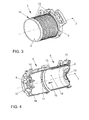
- the serving for cooling the electric machine 1 and designed as a sleeve cooling jacket 4 will be described below with reference to the FIG. 2 explained in more detail.
- This consists of a cylindrical inner shell 5, which is also referred to as a stator support, and a likewise outer shell 6, which is also cylindrical and concentrically arranged, which encloses the inner shell 5 at least in sections.
- a central longitudinal axis 7 of the cooling jacket 4 is arranged coaxially with the axis of rotation 2 of the rotor or the shaft 3.
- An intended for receiving the stator interior 8 of the cooling jacket 4 is bounded radially by the inner shell 5 and the outer shell 6 and axially by two end shields 9, wherein in each case a bearing plate 9 is integrally connected to the inner shell 5 and the outer shell 6.
- the bearing plates 9 each have an opening 10.
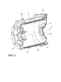
- the outer shell 6 and the inner shell 5 include a cooling space 11 through which a coolant can flow and which is designed as an annular gap.
- a cooling space 11 through which a coolant can flow and which is designed as an annular gap.
- the two adhesive bonds 12 are arranged on both sides of the cooling space 11 and delimit this in the axial direction, so that the cooling space 11 is hermetically sealed by the adhesive joints 12.
- Adhesive surfaces 13 of the inner shell 5 are adhesively bonded in the region of the adhesive connections 12 with corresponding adhesive surfaces 14 of the outer shell 6 by a hardened adhesive.
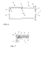
- an adhesive is first applied to the adhesive surfaces 13 of the inner shell 5 and / or the adhesive surfaces 14 of the outer shell 6. Subsequently, the inner shell 5 is moved in a joining direction 15 relative to the outer shell 6, so that initially an insertion section 16 of the inner shell 5 is inserted into a limited by the outer shell 6 insertion opening 17. By a progressive movement of the inner shell 5 in the joining direction 15, the inner shell 5 is then in the in the FIG. 5 arranged assembly position shown.
- the adhesive is applied exclusively to the adhesive surface 13 of the inner shell 5 facing away from the insertion section 16 and to an adhesive surface 14 of the outer shell 6 facing away from the insertion opening 17.
- the adhesive comes into contact with the respectively opposite surfaces of the inner shell 5 or the outer shell 6 only in the final phase of the joining movement, so that beading of the adhesive or sticking of the surfaces of the inner shell 5 and the outer shell 6 delimiting the cooling space 11 is precluded ,
- FIGS. 6 and 7 show another embodiment of the cooling jacket 4, in which the adhesive surfaces 13, 14 in the in FIG. 7 assembly position shown form a cone connection 18.
- the adhesive between them receiving adhesive surfaces 13 of the inner shell 5 and the adhesive surfaces 14 of the outer shell 6 are automatically pressed against each other with a compressive force F, so no external pressure force on the adhesive surfaces 13, 14 must be exercised to a reliable, solid and liquid-tight adhesive bond 12 between the inner shell 5 and the outer shell 6 to ensure.
- the adhesive surfaces 13 of the inner shell 5 are at least partially formed as an inner cone and the adhesive surfaces 14 of the outer shell 6 at least partially as an outer cone.
Applications Claiming Priority (1)
| Application Number | Priority Date | Filing Date | Title |
|---|---|---|---|
| DE102014214724.7A DE102014214724A1 (de) | 2014-07-25 | 2014-07-25 | Kühlmantel für eine elektrische Maschine und Verfahren zur Montage des Kühlmantels sowie eine mit einem Kühlmantel ausgestattete elektrische Maschine |
Publications (3)
| Publication Number | Publication Date |
|---|---|
| EP2978108A2 true EP2978108A2 (fr) | 2016-01-27 |
| EP2978108A3 EP2978108A3 (fr) | 2016-03-16 |
| EP2978108B1 EP2978108B1 (fr) | 2017-08-23 |
Family
ID=53180546
Family Applications (1)
| Application Number | Title | Priority Date | Filing Date |
|---|---|---|---|
| EP15166570.0A Not-in-force EP2978108B1 (fr) | 2014-07-25 | 2015-05-06 | Chemise réfrigérante pour une machine électrique et procédé de montage de la chemise réfrigérante et machine électrique équipée d'une chemise réfrigérante |
Country Status (3)
| Country | Link |
|---|---|
| EP (1) | EP2978108B1 (fr) |
| CN (1) | CN105281495B (fr) |
| DE (1) | DE102014214724A1 (fr) |
Cited By (4)
| Publication number | Priority date | Publication date | Assignee | Title |
|---|---|---|---|---|
| FR3052934A1 (fr) * | 2016-06-15 | 2017-12-22 | Valeo Equip Electr Moteur | Machine electrique tournante munie d'un palier en deux parties |
| WO2021019058A1 (fr) * | 2019-07-31 | 2021-02-04 | Fraunhofer-Gesellschaft zur Förderung der angewandten Forschung e.V. | Carter moteur et procédé de fabrication d'un carter moteur |
| EP3829029A1 (fr) * | 2019-11-27 | 2021-06-02 | Robert Bosch GmbH | Agencement de boitier d'une unité d'entraînement électrique |
| DE102022203244A1 (de) | 2022-04-01 | 2023-10-05 | Volkswagen Aktiengesellschaft | Gehäuse für eine elektrische Maschine, Bausatz zu dessen Aufbau und Antriebsanordnung |
Families Citing this family (8)
| Publication number | Priority date | Publication date | Assignee | Title |
|---|---|---|---|---|
| DE102016215187A1 (de) | 2016-08-16 | 2018-02-22 | Volkswagen Aktiengesellschaft | Gehäuseanordnung für eine elektrische Maschine mit geklemmtem Stator |
| DE102016217361A1 (de) | 2016-09-12 | 2018-03-15 | Volkswagen Aktiengesellschaft | Rotatorische Elektromaschine |
| DE102016218154A1 (de) * | 2016-09-21 | 2018-03-22 | Zf Friedrichshafen Ag | Elektrische Antriebseinheit mit Kühlhülse |
| DE102016222051A1 (de) | 2016-11-10 | 2018-05-17 | Volkswagen Aktiengesellschaft | Gehäuseanordnung für eine elektrische Maschine mit Kühlmantel |
| CN109104032A (zh) * | 2018-10-18 | 2018-12-28 | 濮阳市华南重工科技有限公司 | 电机及其冷却壳体结构 |
| DE102018129401B4 (de) * | 2018-11-22 | 2021-01-14 | Carl Freudenberg Kg | Mantelkühlsystem |
| DE102020211432A1 (de) | 2020-09-11 | 2022-03-17 | Robert Bosch Gesellschaft mit beschränkter Haftung | Elektrische Antriebseinheit und ein Fahrzeug mit einer entsprechenden elektrischen Antriebseinheit |
| CN114530989A (zh) * | 2022-03-01 | 2022-05-24 | 臻驱科技(上海)有限公司 | 一种油冷驱动电机及其装配方法 |
Citations (2)
| Publication number | Priority date | Publication date | Assignee | Title |
|---|---|---|---|---|
| EP1953897A2 (fr) | 2007-02-01 | 2008-08-06 | Honeywell International Inc. | Chemise de refroidissement pour moteur électrique |
| DE102012016208A1 (de) | 2012-08-16 | 2014-02-20 | Volkswagen Aktiengesellschaft | Aggregat und Gehäuse mit einem Kühlmantel |
Family Cites Families (4)
| Publication number | Priority date | Publication date | Assignee | Title |
|---|---|---|---|---|
| DE19624519A1 (de) * | 1996-06-20 | 1998-01-02 | Bosch Gmbh Robert | Flüssigkeitskühlung von elektrischen Maschinen |
| DE102010042259A1 (de) * | 2010-10-11 | 2012-04-12 | Robert Bosch Gmbh | Elektromaschine |
| DE102012205754A1 (de) * | 2012-04-10 | 2013-10-10 | Continental Automotive Gmbh | Gehäuse für eine rotierende elektrische Maschine |
| DE102012023050A1 (de) * | 2012-11-26 | 2014-05-28 | Volkswagen Aktiengesellschaft | Elektrische Maschine und Verfahren zur Herstellung einer elektrischen Maschine |
-
2014
- 2014-07-25 DE DE102014214724.7A patent/DE102014214724A1/de not_active Withdrawn
-
2015
- 2015-05-06 EP EP15166570.0A patent/EP2978108B1/fr not_active Not-in-force
- 2015-07-24 CN CN201510440673.3A patent/CN105281495B/zh not_active Expired - Fee Related
Patent Citations (2)
| Publication number | Priority date | Publication date | Assignee | Title |
|---|---|---|---|---|
| EP1953897A2 (fr) | 2007-02-01 | 2008-08-06 | Honeywell International Inc. | Chemise de refroidissement pour moteur électrique |
| DE102012016208A1 (de) | 2012-08-16 | 2014-02-20 | Volkswagen Aktiengesellschaft | Aggregat und Gehäuse mit einem Kühlmantel |
Cited By (4)
| Publication number | Priority date | Publication date | Assignee | Title |
|---|---|---|---|---|
| FR3052934A1 (fr) * | 2016-06-15 | 2017-12-22 | Valeo Equip Electr Moteur | Machine electrique tournante munie d'un palier en deux parties |
| WO2021019058A1 (fr) * | 2019-07-31 | 2021-02-04 | Fraunhofer-Gesellschaft zur Förderung der angewandten Forschung e.V. | Carter moteur et procédé de fabrication d'un carter moteur |
| EP3829029A1 (fr) * | 2019-11-27 | 2021-06-02 | Robert Bosch GmbH | Agencement de boitier d'une unité d'entraînement électrique |
| DE102022203244A1 (de) | 2022-04-01 | 2023-10-05 | Volkswagen Aktiengesellschaft | Gehäuse für eine elektrische Maschine, Bausatz zu dessen Aufbau und Antriebsanordnung |
Also Published As
| Publication number | Publication date |
|---|---|
| CN105281495B (zh) | 2018-06-08 |
| EP2978108A3 (fr) | 2016-03-16 |
| EP2978108B1 (fr) | 2017-08-23 |
| DE102014214724A1 (de) | 2016-01-28 |
| CN105281495A (zh) | 2016-01-27 |
Similar Documents
| Publication | Publication Date | Title |
|---|---|---|
| EP2978108B1 (fr) | Chemise réfrigérante pour une machine électrique et procédé de montage de la chemise réfrigérante et machine électrique équipée d'une chemise réfrigérante | |
| EP2569848B1 (fr) | Procédé de fabrication d'un moteur électrique | |
| DE102012023050A1 (de) | Elektrische Maschine und Verfahren zur Herstellung einer elektrischen Maschine | |
| EP2135796B1 (fr) | Unité d'entraînement d'engrenage et procédé de fabrication de celle-ci | |
| EP3369159A1 (fr) | Boîtier de refroidissement pour machine électrique et procédé de fabrication | |
| DE102006035697A1 (de) | Maschinengehäuse einer elektrischen Maschine | |
| DE102017203833A1 (de) | Flüssigkeitspumpe | |
| DE102015103053A1 (de) | Elektrodurchführungseinheit | |
| DE102019112830A1 (de) | Spaltrohrmotor mit erhöhtem Wirkungsgrad | |
| DE102018000313A1 (de) | Gehäuse für eine Fahrzeugbatterie eines Kraftwagens sowie Verfahren zum Herstellen eines Gehäuses für eine Kraftfahrzeugbatterie | |
| DE102020117266A1 (de) | Statoranordnung für eine Elektromaschine | |
| DE102011079162A1 (de) | Getriebevorrichtung mit mindestens einem Elektromotor für ein Fahrzeug | |
| DE102011079157B4 (de) | Getriebevorrichtung mit mindestens einem Elektromotor mit radial begrenztem Bauraum für ein Fahrzeug | |
| DE19935723B4 (de) | Verfahren zur Herstellung einer Elektromotoranordnung | |
| EP3114754B1 (fr) | Machine électrique, par exemple pour un générateur de courant | |
| DE102011017041A1 (de) | Fluiddynamisches Lagersystem | |
| DE102021126459A1 (de) | Gehäuse für einen elektrischen Antrieb eines Kraftfahrzeugs, Kraftfahrzeug sowie Verfahren | |
| DE102019216567A1 (de) | Elektrische Maschine umfassend eine Kühlhülse | |
| DE102015221776A1 (de) | Gehäuseanordnung für eine elektrische Maschine | |
| DE102016215187A1 (de) | Gehäuseanordnung für eine elektrische Maschine mit geklemmtem Stator | |
| DE102014224022A1 (de) | Stator | |
| DE102016222051A1 (de) | Gehäuseanordnung für eine elektrische Maschine mit Kühlmantel | |
| DE102017007533A1 (de) | Abdichtanordnung eines Statorträgers einer elektrischen Maschine an einem Gehäuse | |
| DE102016218142A1 (de) | Zwischenantriebsmodul | |
| DE102014215292A1 (de) | Antriebsanordnung mit Elektromotor und Drehmomentwandler |
Legal Events
| Date | Code | Title | Description |
|---|---|---|---|
| PUAI | Public reference made under article 153(3) epc to a published international application that has entered the european phase |
Free format text: ORIGINAL CODE: 0009012 |
|
| AK | Designated contracting states |
Kind code of ref document: A2 Designated state(s): AL AT BE BG CH CY CZ DE DK EE ES FI FR GB GR HR HU IE IS IT LI LT LU LV MC MK MT NL NO PL PT RO RS SE SI SK SM TR |
|
| AX | Request for extension of the european patent |
Extension state: BA ME |
|
| PUAL | Search report despatched |
Free format text: ORIGINAL CODE: 0009013 |
|
| AK | Designated contracting states |
Kind code of ref document: A3 Designated state(s): AL AT BE BG CH CY CZ DE DK EE ES FI FR GB GR HR HU IE IS IT LI LT LU LV MC MK MT NL NO PL PT RO RS SE SI SK SM TR |
|
| AX | Request for extension of the european patent |
Extension state: BA ME |
|
| RIC1 | Information provided on ipc code assigned before grant |
Ipc: H02K 5/20 20060101AFI20160211BHEP Ipc: H02K 9/19 20060101ALI20160211BHEP |
|
| 17P | Request for examination filed |
Effective date: 20160916 |
|
| RBV | Designated contracting states (corrected) |
Designated state(s): AL AT BE BG CH CY CZ DE DK EE ES FI FR GB GR HR HU IE IS IT LI LT LU LV MC MK MT NL NO PL PT RO RS SE SI SK SM TR |
|
| 17Q | First examination report despatched |
Effective date: 20161017 |
|
| GRAP | Despatch of communication of intention to grant a patent |
Free format text: ORIGINAL CODE: EPIDOSNIGR1 |
|
| INTG | Intention to grant announced |
Effective date: 20170405 |
|
| GRAS | Grant fee paid |
Free format text: ORIGINAL CODE: EPIDOSNIGR3 |
|
| GRAA | (expected) grant |
Free format text: ORIGINAL CODE: 0009210 |
|
| AK | Designated contracting states |
Kind code of ref document: B1 Designated state(s): AL AT BE BG CH CY CZ DE DK EE ES FI FR GB GR HR HU IE IS IT LI LT LU LV MC MK MT NL NO PL PT RO RS SE SI SK SM TR |
|
| REG | Reference to a national code |
Ref country code: GB Ref legal event code: FG4D Free format text: NOT ENGLISH |
|
| REG | Reference to a national code |
Ref country code: CH Ref legal event code: EP |
|
| REG | Reference to a national code |
Ref country code: AT Ref legal event code: REF Ref document number: 922303 Country of ref document: AT Kind code of ref document: T Effective date: 20170915 |
|
| REG | Reference to a national code |
Ref country code: IE Ref legal event code: FG4D Free format text: LANGUAGE OF EP DOCUMENT: GERMAN |
|
| REG | Reference to a national code |
Ref country code: DE Ref legal event code: R096 Ref document number: 502015001716 Country of ref document: DE |
|
| REG | Reference to a national code |
Ref country code: NL Ref legal event code: FP |
|
| REG | Reference to a national code |
Ref country code: LT Ref legal event code: MG4D |
|
| PG25 | Lapsed in a contracting state [announced via postgrant information from national office to epo] |
Ref country code: SE Free format text: LAPSE BECAUSE OF FAILURE TO SUBMIT A TRANSLATION OF THE DESCRIPTION OR TO PAY THE FEE WITHIN THE PRESCRIBED TIME-LIMIT Effective date: 20170823 Ref country code: FI Free format text: LAPSE BECAUSE OF FAILURE TO SUBMIT A TRANSLATION OF THE DESCRIPTION OR TO PAY THE FEE WITHIN THE PRESCRIBED TIME-LIMIT Effective date: 20170823 Ref country code: LT Free format text: LAPSE BECAUSE OF FAILURE TO SUBMIT A TRANSLATION OF THE DESCRIPTION OR TO PAY THE FEE WITHIN THE PRESCRIBED TIME-LIMIT Effective date: 20170823 Ref country code: HR Free format text: LAPSE BECAUSE OF FAILURE TO SUBMIT A TRANSLATION OF THE DESCRIPTION OR TO PAY THE FEE WITHIN THE PRESCRIBED TIME-LIMIT Effective date: 20170823 Ref country code: NO Free format text: LAPSE BECAUSE OF FAILURE TO SUBMIT A TRANSLATION OF THE DESCRIPTION OR TO PAY THE FEE WITHIN THE PRESCRIBED TIME-LIMIT Effective date: 20171123 |
|
| PG25 | Lapsed in a contracting state [announced via postgrant information from national office to epo] |
Ref country code: PL Free format text: LAPSE BECAUSE OF FAILURE TO SUBMIT A TRANSLATION OF THE DESCRIPTION OR TO PAY THE FEE WITHIN THE PRESCRIBED TIME-LIMIT Effective date: 20170823 Ref country code: LV Free format text: LAPSE BECAUSE OF FAILURE TO SUBMIT A TRANSLATION OF THE DESCRIPTION OR TO PAY THE FEE WITHIN THE PRESCRIBED TIME-LIMIT Effective date: 20170823 Ref country code: ES Free format text: LAPSE BECAUSE OF FAILURE TO SUBMIT A TRANSLATION OF THE DESCRIPTION OR TO PAY THE FEE WITHIN THE PRESCRIBED TIME-LIMIT Effective date: 20170823 Ref country code: GR Free format text: LAPSE BECAUSE OF FAILURE TO SUBMIT A TRANSLATION OF THE DESCRIPTION OR TO PAY THE FEE WITHIN THE PRESCRIBED TIME-LIMIT Effective date: 20171124 Ref country code: BG Free format text: LAPSE BECAUSE OF FAILURE TO SUBMIT A TRANSLATION OF THE DESCRIPTION OR TO PAY THE FEE WITHIN THE PRESCRIBED TIME-LIMIT Effective date: 20171123 Ref country code: RS Free format text: LAPSE BECAUSE OF FAILURE TO SUBMIT A TRANSLATION OF THE DESCRIPTION OR TO PAY THE FEE WITHIN THE PRESCRIBED TIME-LIMIT Effective date: 20170823 Ref country code: IS Free format text: LAPSE BECAUSE OF FAILURE TO SUBMIT A TRANSLATION OF THE DESCRIPTION OR TO PAY THE FEE WITHIN THE PRESCRIBED TIME-LIMIT Effective date: 20171223 |
|
| PG25 | Lapsed in a contracting state [announced via postgrant information from national office to epo] |
Ref country code: CZ Free format text: LAPSE BECAUSE OF FAILURE TO SUBMIT A TRANSLATION OF THE DESCRIPTION OR TO PAY THE FEE WITHIN THE PRESCRIBED TIME-LIMIT Effective date: 20170823 Ref country code: DK Free format text: LAPSE BECAUSE OF FAILURE TO SUBMIT A TRANSLATION OF THE DESCRIPTION OR TO PAY THE FEE WITHIN THE PRESCRIBED TIME-LIMIT Effective date: 20170823 Ref country code: RO Free format text: LAPSE BECAUSE OF FAILURE TO SUBMIT A TRANSLATION OF THE DESCRIPTION OR TO PAY THE FEE WITHIN THE PRESCRIBED TIME-LIMIT Effective date: 20170823 |
|
| REG | Reference to a national code |
Ref country code: DE Ref legal event code: R097 Ref document number: 502015001716 Country of ref document: DE |
|
| REG | Reference to a national code |
Ref country code: FR Ref legal event code: PLFP Year of fee payment: 4 |
|
| PG25 | Lapsed in a contracting state [announced via postgrant information from national office to epo] |
Ref country code: SM Free format text: LAPSE BECAUSE OF FAILURE TO SUBMIT A TRANSLATION OF THE DESCRIPTION OR TO PAY THE FEE WITHIN THE PRESCRIBED TIME-LIMIT Effective date: 20170823 Ref country code: SK Free format text: LAPSE BECAUSE OF FAILURE TO SUBMIT A TRANSLATION OF THE DESCRIPTION OR TO PAY THE FEE WITHIN THE PRESCRIBED TIME-LIMIT Effective date: 20170823 Ref country code: IT Free format text: LAPSE BECAUSE OF FAILURE TO SUBMIT A TRANSLATION OF THE DESCRIPTION OR TO PAY THE FEE WITHIN THE PRESCRIBED TIME-LIMIT Effective date: 20170823 Ref country code: EE Free format text: LAPSE BECAUSE OF FAILURE TO SUBMIT A TRANSLATION OF THE DESCRIPTION OR TO PAY THE FEE WITHIN THE PRESCRIBED TIME-LIMIT Effective date: 20170823 |
|
| PLBE | No opposition filed within time limit |
Free format text: ORIGINAL CODE: 0009261 |
|
| STAA | Information on the status of an ep patent application or granted ep patent |
Free format text: STATUS: NO OPPOSITION FILED WITHIN TIME LIMIT |
|
| 26N | No opposition filed |
Effective date: 20180524 |
|
| PG25 | Lapsed in a contracting state [announced via postgrant information from national office to epo] |
Ref country code: SI Free format text: LAPSE BECAUSE OF FAILURE TO SUBMIT A TRANSLATION OF THE DESCRIPTION OR TO PAY THE FEE WITHIN THE PRESCRIBED TIME-LIMIT Effective date: 20170823 |
|
| PG25 | Lapsed in a contracting state [announced via postgrant information from national office to epo] |
Ref country code: MT Free format text: LAPSE BECAUSE OF FAILURE TO SUBMIT A TRANSLATION OF THE DESCRIPTION OR TO PAY THE FEE WITHIN THE PRESCRIBED TIME-LIMIT Effective date: 20170823 |
|
| REG | Reference to a national code |
Ref country code: CH Ref legal event code: PL |
|
| REG | Reference to a national code |
Ref country code: BE Ref legal event code: MM Effective date: 20180531 |
|
| PG25 | Lapsed in a contracting state [announced via postgrant information from national office to epo] |
Ref country code: MC Free format text: LAPSE BECAUSE OF FAILURE TO SUBMIT A TRANSLATION OF THE DESCRIPTION OR TO PAY THE FEE WITHIN THE PRESCRIBED TIME-LIMIT Effective date: 20170823 |
|
| REG | Reference to a national code |
Ref country code: IE Ref legal event code: MM4A |
|
| PG25 | Lapsed in a contracting state [announced via postgrant information from national office to epo] |
Ref country code: CH Free format text: LAPSE BECAUSE OF NON-PAYMENT OF DUE FEES Effective date: 20180531 Ref country code: LI Free format text: LAPSE BECAUSE OF NON-PAYMENT OF DUE FEES Effective date: 20180531 |
|
| PG25 | Lapsed in a contracting state [announced via postgrant information from national office to epo] |
Ref country code: LU Free format text: LAPSE BECAUSE OF NON-PAYMENT OF DUE FEES Effective date: 20180506 |
|
| PG25 | Lapsed in a contracting state [announced via postgrant information from national office to epo] |
Ref country code: IE Free format text: LAPSE BECAUSE OF NON-PAYMENT OF DUE FEES Effective date: 20180506 |
|
| PG25 | Lapsed in a contracting state [announced via postgrant information from national office to epo] |
Ref country code: BE Free format text: LAPSE BECAUSE OF NON-PAYMENT OF DUE FEES Effective date: 20180531 |
|
| PG25 | Lapsed in a contracting state [announced via postgrant information from national office to epo] |
Ref country code: TR Free format text: LAPSE BECAUSE OF FAILURE TO SUBMIT A TRANSLATION OF THE DESCRIPTION OR TO PAY THE FEE WITHIN THE PRESCRIBED TIME-LIMIT Effective date: 20170823 |
|
| PG25 | Lapsed in a contracting state [announced via postgrant information from national office to epo] |
Ref country code: PT Free format text: LAPSE BECAUSE OF FAILURE TO SUBMIT A TRANSLATION OF THE DESCRIPTION OR TO PAY THE FEE WITHIN THE PRESCRIBED TIME-LIMIT Effective date: 20170823 |
|
| PG25 | Lapsed in a contracting state [announced via postgrant information from national office to epo] |
Ref country code: CY Free format text: LAPSE BECAUSE OF FAILURE TO SUBMIT A TRANSLATION OF THE DESCRIPTION OR TO PAY THE FEE WITHIN THE PRESCRIBED TIME-LIMIT Effective date: 20170823 Ref country code: HU Free format text: LAPSE BECAUSE OF FAILURE TO SUBMIT A TRANSLATION OF THE DESCRIPTION OR TO PAY THE FEE WITHIN THE PRESCRIBED TIME-LIMIT; INVALID AB INITIO Effective date: 20150506 Ref country code: MK Free format text: LAPSE BECAUSE OF NON-PAYMENT OF DUE FEES Effective date: 20170823 |
|
| PG25 | Lapsed in a contracting state [announced via postgrant information from national office to epo] |
Ref country code: AL Free format text: LAPSE BECAUSE OF FAILURE TO SUBMIT A TRANSLATION OF THE DESCRIPTION OR TO PAY THE FEE WITHIN THE PRESCRIBED TIME-LIMIT Effective date: 20170823 |
|
| PGFP | Annual fee paid to national office [announced via postgrant information from national office to epo] |
Ref country code: FR Payment date: 20200527 Year of fee payment: 6 Ref country code: DE Payment date: 20200531 Year of fee payment: 6 Ref country code: NL Payment date: 20200526 Year of fee payment: 6 |
|
| PGFP | Annual fee paid to national office [announced via postgrant information from national office to epo] |
Ref country code: GB Payment date: 20200528 Year of fee payment: 6 |
|
| REG | Reference to a national code |
Ref country code: AT Ref legal event code: MM01 Ref document number: 922303 Country of ref document: AT Kind code of ref document: T Effective date: 20200506 |
|
| PG25 | Lapsed in a contracting state [announced via postgrant information from national office to epo] |
Ref country code: AT Free format text: LAPSE BECAUSE OF NON-PAYMENT OF DUE FEES Effective date: 20200506 |
|
| REG | Reference to a national code |
Ref country code: DE Ref legal event code: R119 Ref document number: 502015001716 Country of ref document: DE |
|
| REG | Reference to a national code |
Ref country code: NL Ref legal event code: MM Effective date: 20210601 |
|
| GBPC | Gb: european patent ceased through non-payment of renewal fee |
Effective date: 20210506 |
|
| PG25 | Lapsed in a contracting state [announced via postgrant information from national office to epo] |
Ref country code: GB Free format text: LAPSE BECAUSE OF NON-PAYMENT OF DUE FEES Effective date: 20210506 Ref country code: DE Free format text: LAPSE BECAUSE OF NON-PAYMENT OF DUE FEES Effective date: 20211201 |
|
| PG25 | Lapsed in a contracting state [announced via postgrant information from national office to epo] |
Ref country code: NL Free format text: LAPSE BECAUSE OF NON-PAYMENT OF DUE FEES Effective date: 20210601 Ref country code: FR Free format text: LAPSE BECAUSE OF NON-PAYMENT OF DUE FEES Effective date: 20210531 |