EP1953897A2 - Chemise de refroidissement pour moteur électrique - Google Patents
Chemise de refroidissement pour moteur électrique Download PDFInfo
- Publication number
- EP1953897A2 EP1953897A2 EP08101076A EP08101076A EP1953897A2 EP 1953897 A2 EP1953897 A2 EP 1953897A2 EP 08101076 A EP08101076 A EP 08101076A EP 08101076 A EP08101076 A EP 08101076A EP 1953897 A2 EP1953897 A2 EP 1953897A2
- Authority
- EP
- European Patent Office
- Prior art keywords
- inner sleeve
- cooling jacket
- sleeve
- cooling
- outer sleeve
- Prior art date
- Legal status (The legal status is an assumption and is not a legal conclusion. Google has not performed a legal analysis and makes no representation as to the accuracy of the status listed.)
- Withdrawn
Links
Images


Classifications
-
- H—ELECTRICITY
- H02—GENERATION; CONVERSION OR DISTRIBUTION OF ELECTRIC POWER
- H02K—DYNAMO-ELECTRIC MACHINES
- H02K5/00—Casings; Enclosures; Supports
- H02K5/04—Casings or enclosures characterised by the shape, form or construction thereof
- H02K5/20—Casings or enclosures characterised by the shape, form or construction thereof with channels or ducts for flow of cooling medium
- H02K5/203—Casings or enclosures characterised by the shape, form or construction thereof with channels or ducts for flow of cooling medium specially adapted for liquids, e.g. cooling jackets
-
- Y—GENERAL TAGGING OF NEW TECHNOLOGICAL DEVELOPMENTS; GENERAL TAGGING OF CROSS-SECTIONAL TECHNOLOGIES SPANNING OVER SEVERAL SECTIONS OF THE IPC; TECHNICAL SUBJECTS COVERED BY FORMER USPC CROSS-REFERENCE ART COLLECTIONS [XRACs] AND DIGESTS
- Y10—TECHNICAL SUBJECTS COVERED BY FORMER USPC
- Y10T—TECHNICAL SUBJECTS COVERED BY FORMER US CLASSIFICATION
- Y10T29/00—Metal working
- Y10T29/49—Method of mechanical manufacture
- Y10T29/4935—Heat exchanger or boiler making
- Y10T29/49359—Cooling apparatus making, e.g., air conditioner, refrigerator
Definitions
- the present invention generally relates to electric motors/generators and electrically driven compressors and, more particularly, to a cooling jacket of a dry-liquid cooled electric motor/generator and a method for dry liquid cooling an electric motor/generator of an electrically driven compressor.
- Electric motors or generators typically generate a substantial amount of heat during operation, especially if operated at high speeds. Consequently, an electric motor or generator needs to be cooled in order to avoid damage and to ensure smooth and efficient operation of the motor or generator. Since the heat transfer coefficient for cooling using a liquid is generally much higher than the heat transfer coefficient for air, the stator of an electric motor or generator is often cooled with a liquid coolant.
- stator iron stack and the stator winding end turns are typically completely immersed in a cooling liquid, such as oil. Heat is extracted from the stator by conducting the heat from the stator core and winding to the cooling liquid.
- Wet liquid cooling of the stator requires sealing the rotor from the space surrounding the stator and is limited to the use of nonconductive liquids, since the stator winding end turns typically are immersed in the cooling liquid as well.
- Dry liquid cooling of the stator is often used as an alternative to wet liquid cooling and utilizes in many cases a cooling jacket that surrounds the iron stack and winding of the stator, for example, U.S. Patent 5,220,233 , U.S. Patent 5,923,108 , U.S. Patent 6,617,715 , and U.S. Patent 6,909,210 .
- a cooling liquid which may be a conductive liquid such as water or a water-based cooling liquid, is typically circulated through channels within the cooling jacket and heat is transferred from the stator through direct contact of the stator with the cooling jacket.
- U.S. Patent 6,900,561 discloses a cooling jacket where the cooling liquid enters the cooling jacket axially in an inclined plane and exits the cooling jacket radially from an inclined plane, which may cause pressure losses in the liquid cooling loop.
- U.S. Patent 5,220,233 and U.S. Patent 3,567,975 the cooling liquid travels in helical channels and enters/exits these channels radially, which may lead to even higher pressure losses and uneven distribution of the cooling liquid.
- U.S. Patent 5,923,108 may be manufactured form cast iron and, therefore, may be too heavy for aerospace applications. Furthermore, cooling jackets manufactured from iron-based materials may be prone to corrosion. Corrosion products that may build-up within the cooling jacket over time may cause degradation of the heat transfer capability of the cooling jacket.
- a cooling jacket that is leak proof and pressure tight, that minimizes pressure losses in the liquid cooling loop, and that has a reduced susceptibility to corrosion. Furthermore, there is a need for a cooling jacket that may be manufactured at a lower cost and that may be easier to assemble and to integrate into electrically driven machines than prior art cooling jackets. Still further, there is a need for a method for dry liquid cooling an electric motor or generator, which has a higher cooling efficiency than prior art dry liquid cooling methods and is also applicable in the aerospace industry.
- a cooling jacket comprises a cylindrical inner sleeve, a cylindrical outer sleeve, and a passageway.
- the outer sleeve coaxially surrounds the inner sleeve forming a circular space between the outer sleeve and the inner sleeve.
- the passageway extends within the circular space between the outer sleeve and the inner sleeve and is a continuous winding path that extends axially back and forth along the circumference of the inner sleeve.
- a cooling jacket of a dry-liquid cooled electric motor or generator comprises a cylindrical inner sleeve extending longitudinally along an axis, a cylindrical outer sleeve, a first and a second weld joint, a plurality of fins that form a passageway, a first opening and a second opening, a cylindrical bearing housing, and a stator stop.
- the inner sleeve forms a cylindrical hollow space, and the hollow space receives a stator of the electric motor or generator.
- the outer sleeve coaxially surrounds the inner sleeve forming a circular space between the outer sleeve and the inner sleeve.
- the first and the second weld joint permanently attach the outer sleeve to the inner sleeve and hermetically seal the circular space between the outer sleeve and the inner sleeve.
- the passageway is a continuous winding path that extends axially back and forth along the circumference of the inner sleeve within the circular space between the outer sleeve and the inner sleeve.
- the first and second opening are positioned across from each other, provide access to the circular space between the inner sleeve and the outer sleeve, and are in fluid connection with the passageway.
- the bearing housing is integrated into the inner sleeve and is axially placed within the hollow space formed by the inner sleeve and receives a bearing of the electric motor or generator.
- the stator stop is an axially extending area of the inner surface of the inner sleeve that has a smaller diameter that adjacent areas and contacts an end of a stator of the electric motor or generator.
- a method for dry liquid cooling an electric motor or generator comprises the steps of: axially passing a cooling liquid from a back end of a cooling jacket through a first opening into a passageway of the cooling jacket, letting the cooling liquid flow axially back and forth through the passageway along both sides of the circumference of an inner surface of the cooling jacket, and axially passing the cooling liquid out of the passageway of the cooling jacket through a second opening positioned at the back end and across from the first opening.
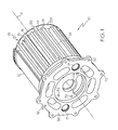
- Figure 1 is a perspective cut-away view of an electric motor cooling jacket according to an embodiment of the present invention
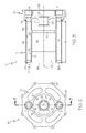
- Figure 2 is a rear view of an electric motor cooling jacket according to an embodiment of the present invention.
- Figure 3 is a cross-sectional side view along line 3-3 of the electric motor cooling jacket of Figure 2 ;
- Figure 4A is a cross-sectional front view of an inner sleeve of a cooling jacket according to an embodiment of the present invention
- Figure 4B is a spread-out top view of an inner sleeve of a cooling jacket according to an embodiment of the present invention
- Figure 5 is a schematic cross-sectional side view of an electrically driven compressor according to an embodiment of the present invention.
- Figure 6 is a flow chart representing a method for dry liquid cooling an electric motor according to an embodiment of the present invention.
- the present invention provides a cooling jacket of a dry-liquid cooled electric motor or generator and a method for dry liquid cooling an electric motor or generator.
- the present invention provides a cooling jacket of an electric motor or generator that is leak proof and pressure tight, that has a compact design that eliminates the need for "o"-rings, that can be manufactured at a low cost, and that may be easily assembled and integrated into an electrically driven machine, such as an electrically driven compressor.
- An embodiment of the present invention provides a cooling jacket that is suitable for, but not limited to, applications in the aircraft and aerospace industries, for example, in air-conditioning systems.
- the cooling jacket and method for dry liquid cooling an electric motor or generator as in one embodiment of the present invention may be suitable, but not limited to, cooling a high power density electric motor or generator. Furthermore, the cooling jacket as in an embodiment of the present invention may be used in connection with any electric motor or generator that requires dry liquid cooling.
- the cooling jacket as in one embodiment of the present invention consists of only two parts, an inner sleeve and an outer sleeve that are connected to each other by two weld joints to form a leak proof and pressure tight cooling jacket. Therefore, by using the cooling jacket as in one embodiment of the present invention, prior art seals and "o"-rings may be eliminated along with the risk of leakage.
- the cooling jacket as in one embodiment of the present invention may be manufactured out of aluminum or aluminum alloys that are suitable for pressure die casting, investment casting, or injection molding.
- the susceptibility to corrosion may be reduced and over time loss of heat transfer capability caused by corrosion products may be prevented.
- the cooling jacket as in one embodiment of the present invention may be lightweight.
- a casting process such as pressure die casting, investment casting, or injection molding, may be used to manufacture the cooling jacket as in one embodiment of the present invention.
- Using a casting or molding process to manufacture the cooling jacket as in one embodiment of the present invention may allow reducing the number of parts that need to be assembled to two, whereas prior art cooling jackets often include more than two parts that need to be assembled.
- using a casting or molding process to manufacture the cooling jacket instead of prior art machining may enable building features - such as an integrated bearing housing and an integrated stop for the stator iron stack - directly into the cooling jacket as in one embodiment of the present invention.
- Integration of such features may enable simple and easy integration of the cooling jacket as in one embodiment of the present invention into an electrically driven machine, such as a compressor. Since bearing alignments are crucial in the assembly of an machine, integrating installation guides and bearing housings into the cooling jacket as in one embodiment of the present invention may also eliminate the need to match set housings during the installation process of the cooling jacket into the electrically driven machine, for example, a cabin air compressor of an aircraft. Consequently, the manufacturing and installation costs of the cooling jacket as in one embodiment of the present invention may be reduced compared to manufacturing and installation costs of prior art cooling jackets.
- the inner sleeve of the cooling jacket as in one embodiment of the present invention may include fins that form axially oriented passageways in which the cooling liquid may travel circumferentially in an axial direction.
- the passageway as in one embodiment of the present invention enables the cooling liquid to stay and travel within the cooling jacket for a longer time, increasing the efficiency of the heat transfer from the stator to the cooling jacket compared to prior art cooling jackets.
- FIG. 1 a perspective view of a cooling jacket 10 of an electric motor 40 (shown in Figure 5 ) is illustrated according to an embodiment of the present invention.
- the cooling jacket 10 may also be used for cooling an electric generator 40.
- the cooling jacket 10 may extend longitudinally along an axis 11 from a front end 35 to a back end 36.
- the cooling jacket 10 may include an outer sleeve 12 shown cut away and an inner sleeve 13.
- the outer sleeve 12 and the inner sleeve 13 may both have a cylindrical shape and may extend coaxially along the axis 11.
- the outer sleeve 12 may surround the inner sleeve 13 forming a circular space 19 between the outer sleeve 12 and the inner sleeve 13.
- the inner sleeve 13 may have a cylindrical outer surface 22 that may extend axially from the front end 35 for a length 18 ( Figure 3 ).
- a first vertical wall 331 may extend vertically at the front end 35 and a second vertical wall 332 may extend vertically proximate to the backend 36. Walls 331 and 332 may define the length 18.
- the inner sleeve 13 may include a plurality of fins 14 that may extend vertically from the outer surface 22 (shown in Figure 3 ) into the circular space 19 (shown in Figure 3 ) along the circumference of the inner sleeve 13.
- the fins 14 may be positioned in an interlocking-finger arrangement to form a passageway 15.
- the passageway 15 may allow a cooling liquid 30 ( Figures 4B and 5 ) to travel axially along the circumference of the inner sleeve 13.
- the passageway 15 may be a continuous winding path that extends axially along the circumference of the inner sleeve 13 within the circular space 19 and that enables the cooling liquid 30 to travel axially back and forth over the length 18 (shown in Figure 3 ) of the inner sleeve 13 along the circumference of the inner sleeve 13.
- the cooling liquid 30 may be a water-based liquid coolant, for example, a propylene glycol water (PGW) coolant that may contain about 60% propylene glycol and about 40% water.
- PGW propylene glycol water
- the inner sleeve 13 may include an end section 16.
- the end section 16 may include two openings 17 positioned across from each other. Each of the openings 17 may provide access to the space 19 (shown in Figure 3 ) between the outer sleeve 12 and the inner sleeve 13 and to the passageway 15.
- Each of the openings 17 may be used as either an inlet or an outlet for the cooling liquid 30, whereas always a first opening 17 may function as an inlet for the cooling liquid 30 and the other, second opening 17 may function as an outlet for the cooling liquid 30, concurrently.
- Each of the openings 17 may be in fluid connection with a portion 151 of the passageway 15.
- the passageway 15 may include two portions 151 leading either to or from the openings 17 that may have a larger width than the remaining portions of the passageway 15.
- the end section 16 may further include mounting holes 20 and 32 that assist integration of the cooling jacket 10 into an electrically driven machine, such as a compressor 50 (as shown in Figure 5 ).
- the inner sleeve 13 may further have a cylindrical inner surface 21 that forms a hollow space 23 for receiving a stator 41 of an electric motor or generator 40 (shown in Figure 5 ).
- the inner sleeve 13 may further include a cylindrical bearing housing 24 axially placed within the hollow space 23 proximate to the end section 16 (also shown in Figure 3 ).
- the outer sleeve 12 may have a smooth cylindrical inner surface 25 and may be coaxially disposed around the inner sleeve 13.
- the outer sleeve 12 may fit tight on the inner sleeve 13 but may not completely seal the passageways 15 and 151.
- Each, the outer sleeve 12 and the inner sleeve 13, may be manufactured as a single piece cast during pressure die-casting, investment casting, or injection molding.
- the outer sleeve 12 and the inner sleeve 13 may be manufactured from aluminum and aluminum alloys.
- FIG. 2 a rear view of the cooling jacket 10 of the electric motor or generator 40 (shown in Figure 5 ) is illustrated according to an embodiment of the present invention.
- Shown in Figure 2 is the end section 16 including the openings 17, the opening 26 of the bearing housing 24, and the mounting holes 20 and 32.
- the opening 26 of the bearing housing may be positioned in the center 27 of the cooling jacket 10.
- the mounting holes 20 may be evenly distributed along the circumference of the end section 16 in close proximity to the outer edge of the end section 16.
- Mounting holes 20 may receive bolts 28 ( Figure 5 ) and mounting holes 20 and 32 may assist the installation of the cooling jacket 10 in the compressor 50 ( Figure 5 ).
- a line 3-3 may vertically advance through the center 27 of the cooling jacket 10. As can be seen, the openings 17 may be centered on the line 3-3.
- FIG. 3 a cross-sectional side view along line 3-3 of the cooling jacket 10 of Figure 2 is illustrated according to an embodiment of the present invention.
- Figure 3 is a vertical cross-section through the center of the openings 17.
- the cooling jacket 10 may extend axially from a front end 35 to a back end 36.
- An end section 16 may be positioned at the back end 36.
- each opening 17 may be in fluid connection with a portion 151 of the passageway 15.
- the bearing housing 24 may be integrated in the inner sleeve 13 in close proximity to the end section 16 and may extend coaxially along axis 11.
- the outer sleeve 12 may be coaxially disposed around the inner sleeve 13.
- Two weld joints 29 may secure the outer sleeve 12 to the inner sleeve 13 and may hermetically seal the circular space 19 between the outer sleeve 12 and the inner sleeve 13.
- the first weld 29 joint may be positioned where the outer sleeve 12 meets the end section 16 of the inner sleeve 13 and the second weld joint 29 may be positioned where the outer sleeve 12 meets the vertical wall 331 that may be positioned opposite from the front end 35.
- the cylindrical inner surface 21 of the inner sleeve 13 may include a stator stop 31, which may be an axially extending area of the inner surface that may have a smaller diameter than the adjacent areas.
- the stator stop 31 may contact an end of the stator 41 of the electric motor or generator 40 ( Figure 5 ).
- the inner surface 21 may further include an axially extending section 34 for receiving the iron stack 42 ( Figure 5 ) of an electric motor or generator 40.
- the section 34 may be positioned adjacent to the stator stop 31 and between the front end 35 and the stator stop 31 and may have a diameter that may be larger than the diameter of the stator stop 31.
- the diameter of the section 34 may be chosen such that the section 34 is in direct contact with the iron stack 42 ( Figure 5 ).
- FIG. 4A und 4B a cross-sectional front view and a spread-out top view of an inner sleeve 13 of a cooling jacket 10 is illustrated, respectively, according to an embodiment of the present invention.
- the fins 14 may be arranged in parallel to each other.
- the fins 14 may extend axially in the direction of the axis 11 covering most of the length 18 of the inner sleeve 13.
- the fins 14 may alternate ending short of the wall 331 and the wall 332.
- Each two fins 14 that are positioned next to each other may define a portion of the passageway 15 therebetween.
- the passageway 15 may be a continuous winding path that extends around the circumference of the inner sleeve 13.
- a cooling liquid 30 may axially travel along the passageway 15 back and forth over the entire length 18.
- the cooling liquid 30 may enter the passageway 15 at one of the opening 17 and may flow in the direction indicated by arrows 37 toward the other opening 17.
- the portions 151 of the passageway 15 where the cooling liquid 30 may enter or exit the passageway 15 may have a width that may be wider than the remaining portions of the passageway 15.
- the cooling liquid 30 may enter the passageway 15 though a first opening 17, which may extend through the wall 332.
- the cooling liquid 30 may travel axially within a first portion 151 of the passageway 15 towards the wall 331 at the front end 35 of the cooling jacket 10.
- the flow of the cooling liquid 30 may split and the cooling liquid 30 may travel in the passageway 15 to the right and to the left simultaneously.
- the cooling liquid 30 may travel simultaneously in both directions, to the left and to the right, along the circumference of the inner sleeve 13 in axial direction back and forth until it reaches the second portion 151 of the passageway 15 leading to the second opening 17. Since the cooling liquid 30 arrives at the second portion 151 from the left and from the right it may be forced to enter the second portion 151 and to travel in axially direction towards the second opening 17, which may extend through the wall 332. As can be seen, the cooling liquid 30 may enter the passageway 15 of the cooling jacket 10 axially from the back end 36.
- the cooling liquid 30 may further exit the passageway 15 of the cooling jacket 10 through the back end 36. Either opening 17 may be used as exit or entrance for the cooling liquid 30.
- the flow 37 of the cooling liquid 30 is independent from the position, such as vertical or horizontal, of the openings 17 and, therefore, the cooling jacket 10 may be suitable for applications in the aerospace industry. By axially traveling back and forth, the cooling liquid 30 may stay for a relatively long time within the passageway 15, which may enable relatively high heat transfer efficiency.
- the compressor 50 may include an electric motor 40, a compressor housing 51, a connector housing 52, a compressor wheel 53, a tie rod 54, and bearings 55.
- the electric motor 40 may include a cooling jacket 10, a stator 41 having an iron stack 42 and a winding 46 with end turns 44, and a rotor 45.
- the tie rod 54 may connect the compressor wheel 53 with the rotor 45 of the motor 40.
- the cooling jacket 10 may be integrated in the assembly of the compressor 50 and may be sandwiched between the compressor housing 51 and the connector housing 52.
- Bolts 28 may secure the cooling jacket 10 to the compressor housing 51 via mounting holes 20.
- the connector housing 52 may be connected to the cooling jacket 10 utilizing mounting holes 32.
- the compressor 50 may be any type of electrically driven compressor, such as an air compressor, that uses dry liquid cooling.
- the axially extending section 34 of the inner surface 21 of the inner sleeve 13 may be in direct contact with the outer diameter of the iron stack 42 of the stator 41.
- the remaining inner surface 21 of the inner sleeve 13 may be in contact with a potting material 43.
- the potting material 43 may fill the space between end turns 44 of the stator winding 46 and the inner surface 21 of the inner sleeve 13 of the cooling jacket 10.
- the cooling liquid 30 axially traveling in the passageway 15 of the cooling jacket 10 in the direction indicated by arrows 37 may draw heat from the stator 41 including the stator iron stack 42 the winding 46, and the end turns 44 of the stator winding 46.
- the length 18, over which the cooling liquid 30 may axially travel may cover the entire length of the iron stack 42 and the stator winding 46 including end turns 44, which may enable a relatively high heat transfer efficiency.
- the bearing housing 24 may be integrated into the inner sleeve 13 of the cooling jacket 10 and may be sized to receive the bearings 55, which may be, for example, air-foil bearings.
- the bearing housing 24 may assist the bearing alignment during assembly of the compressor 50 and may, therefore, eliminate the need to match set housings, for example, the compressor housing 51, the connector housing 52, the bearing housing 24 and a cooling housing, such as the cooling jacket 10.
- the method 60 may involve a step 61 where a cooling jacket 10 may be installed around a stator 41 an electric motor or generator 40.
- step 62 direct contact of the inner surface 21 of the inner sleeve 13 of the cooling jacket 10 with the outer diameter of the iron stack 42 of the stator 41 may be realized. Further realized may be direct contact of the inner surface 21 of the inner sleeve 13 of the cooling jacket 10 with potting material 43 in a step 63.
- the potting material 43 may fill the space between the inner surface 21 of the inner sleeve 13 of the cooling jacket 10 and the end turns 33 of the winding 46 of the stator 41.
- a step 64 may involve axially passing a cooling liquid 30 from the back end 36 of the cooling jacket 10 through a first opening 17 into the passageway 15.
- a following step 65 may involve letting the cooling liquid 30 axially flow through the passageway 15 along both sides of the circumference of the inner sleeve 13 of the cooling jacket 10.
- a step 66 heat may be drawn from the iron stack 42, the winding 46, and the end turns 44 of the winding 46 with the cooling liquid 30.
- the now heated cooling liquid 30 may axially pass through a second opening 17, which may be positioned at the back end 36 of the cooling jacket 10 and across from the first opening 17, out of the cooling jacket 10.
Applications Claiming Priority (1)
| Application Number | Priority Date | Filing Date | Title |
|---|---|---|---|
| US11/670,371 US7675209B2 (en) | 2007-02-01 | 2007-02-01 | Electric motor cooling jacket |
Publications (1)
| Publication Number | Publication Date |
|---|---|
| EP1953897A2 true EP1953897A2 (fr) | 2008-08-06 |
Family
ID=39092795
Family Applications (1)
| Application Number | Title | Priority Date | Filing Date |
|---|---|---|---|
| EP08101076A Withdrawn EP1953897A2 (fr) | 2007-02-01 | 2008-01-29 | Chemise de refroidissement pour moteur électrique |
Country Status (2)
| Country | Link |
|---|---|
| US (1) | US7675209B2 (fr) |
| EP (1) | EP1953897A2 (fr) |
Cited By (11)
| Publication number | Priority date | Publication date | Assignee | Title |
|---|---|---|---|---|
| EP2154770A1 (fr) * | 2008-08-11 | 2010-02-17 | JS Kanalrobotik GmbH | Dispositif de moteur de fraise pour un robot de nettoyage de calandre |
| EP2299561A3 (fr) * | 2009-09-22 | 2013-04-17 | ArvinMeritor Technology, LLC | Gaine de refroidissement pour moteur |
| DE102012016208A1 (de) | 2012-08-16 | 2014-02-20 | Volkswagen Aktiengesellschaft | Aggregat und Gehäuse mit einem Kühlmantel |
| DE102012016207A1 (de) | 2012-08-16 | 2014-02-20 | Volkswagen Aktiengesellschaft | Wärmetauschereinrichtung und Funktionseinrichtung für die Wärmetauschereinrichtung |
| EP2369723A3 (fr) * | 2010-03-23 | 2015-11-11 | Hamilton Sundstrand Corporation | Agencement de refroidisseur pour machine électrique |
| EP2978108A2 (fr) | 2014-07-25 | 2016-01-27 | Volkswagen Aktiengesellschaft | Chemise réfrigérante pour une machine électrique et procédé de montage de la chemise réfrigérante et machine électrique équipée d'une chemise réfrigérante |
| DE102014222959A1 (de) | 2014-11-11 | 2016-05-12 | Volkswagen Aktiengesellschaft | Kühlmantel für eine elektrische Maschine |
| EP2572438A4 (fr) * | 2010-05-21 | 2017-01-04 | BAE Systems Hägglunds Aktiebolag | Dispositif de refroidissement pour moteur électrique |
| WO2017211800A1 (fr) | 2016-06-06 | 2017-12-14 | Moteurs Leroy-Somer | Carcasse d'une machine electrique à double enveloppe |
| EP2609337A4 (fr) * | 2010-08-25 | 2017-12-27 | Magna Powertrain Inc. | Pompe à eau électrique avec refroidissement de stator |
| DE102018207842A1 (de) * | 2018-05-18 | 2019-11-21 | Volkswagen Aktiengesellschaft | Ein von einem Kühlmittel durchströmbarer Kühlmantel sowie eine mit einem solchen Kühlmantel ausgestattete elektrische Kraft- oder Arbeitsmaschine |
Families Citing this family (80)
| Publication number | Priority date | Publication date | Assignee | Title |
|---|---|---|---|---|
| US8641609B2 (en) * | 2007-10-23 | 2014-02-04 | Zimmer Spine, Inc. | Surgical access system and method of using the same |
| DE102009001387A1 (de) * | 2009-03-06 | 2010-09-09 | Robert Bosch Gmbh | Elektromaschine |
| JP4919108B2 (ja) * | 2009-03-26 | 2012-04-18 | アイシン・エィ・ダブリュ株式会社 | ステータ |
| WO2011041403A2 (fr) * | 2009-09-29 | 2011-04-07 | A. O. Smith Corporation | Moteur électrique refroidi par l'air |
| US9010407B2 (en) * | 2010-04-01 | 2015-04-21 | Mac-Dan Innovations Llc | Waste water heat recovery system |
| CN102959837B (zh) * | 2010-08-30 | 2015-11-25 | 丰田自动车株式会社 | 旋转电机的冷却构造 |
| CN102468709B (zh) * | 2010-11-12 | 2016-06-01 | 奇鋐科技股份有限公司 | 电动马达的水冷结构 |
| CN102651579B (zh) | 2011-02-25 | 2017-03-29 | 德昌电机(深圳)有限公司 | 冷却机构及电机 |
| US20120318479A1 (en) * | 2011-06-14 | 2012-12-20 | Fukuta Electric & Machinery Co., Ltd. | Liquid cooled motor assembly and cover thereof |
| US8546982B2 (en) * | 2011-07-12 | 2013-10-01 | Remy Technologies, Llc | Electric machine module cooling system and method |
| KR20140033505A (ko) * | 2011-07-26 | 2014-03-18 | 닛본 세이고 가부시끼가이샤 | 볼 나사의 베어링장치 |
| DE102011081507B4 (de) * | 2011-08-24 | 2013-06-06 | Schaeffler Technologies AG & Co. KG | Abschirmblech mit Kühlmittelleitung |
| US20130069455A1 (en) * | 2011-09-15 | 2013-03-21 | Colin J. Hamer | Electric machine module cooling system and method |
| US8960038B2 (en) * | 2011-10-01 | 2015-02-24 | Hiwin Technologies Corp. | Motion transmission module with a cooling device |
| US20130081497A1 (en) * | 2011-10-01 | 2013-04-04 | Yueh-Ling Chiu | Motion transmission module with a cooling device |
| JP5663451B2 (ja) * | 2011-10-19 | 2015-02-04 | 株式会社安川電機 | 固定子および回転電機 |
| TWI455461B (zh) * | 2011-11-23 | 2014-10-01 | Delta Electronics Inc | 冷卻套 |
| TWI477039B (zh) * | 2011-11-23 | 2015-03-11 | Delta Electronics Inc | 冷卻套 |
| US8405262B1 (en) * | 2011-11-30 | 2013-03-26 | Kollmorgen Corporation | Cooling of electric motor with coolant pipe and conduction plates or cups |
| US9024460B2 (en) * | 2012-01-04 | 2015-05-05 | General Electric Company | Waste heat recovery system generator encapsulation |
| US9559569B2 (en) | 2012-02-13 | 2017-01-31 | Ge Aviation Systems Llc | Arrangement for cooling an electric machine with a layer of thermally conducting and electrically insulating material |
| DE102012206442A1 (de) * | 2012-04-19 | 2013-10-24 | Robert Bosch Gmbh | Stator für eine Elektromaschine mit in ein Gehäuse verpressten Wickelköpfen |
| DE102012008209A1 (de) * | 2012-04-21 | 2013-10-24 | Volkswagen Aktiengesellschaft | Elektrische Maschine |
| US9006943B2 (en) | 2012-09-12 | 2015-04-14 | Remy Technologies, L.L.C. | Electro-dynamic machine with coolant chargeable bladder |
| FR2995719B1 (fr) * | 2012-09-20 | 2018-04-27 | Valeo Systemes De Controle Moteur | Actionneur de volet d'un circuit d'air de moteur thermique |
| US20140103757A1 (en) * | 2012-10-16 | 2014-04-17 | Larry Kubes | Electric machine housing |
| TWI574492B (zh) * | 2012-11-19 | 2017-03-11 | 鴻海精密工業股份有限公司 | 馬達裝置及其冷卻治具 |
| WO2014084989A2 (fr) * | 2012-11-28 | 2014-06-05 | Johnson Controls Technology Company | Procédé de refroidissement de moteur pour un compresseur |
| US9843236B2 (en) * | 2012-12-21 | 2017-12-12 | WEG Equipamentos Eletricos S.A.-Motores | Heat exchange system for casings of rotary electric machines |
| DE102013201758A1 (de) * | 2013-02-04 | 2014-08-07 | Schaeffler Technologies Gmbh & Co. Kg | Elektromaschine mit einer Kühleinrichtung und Verfahren zu deren Herstellung |
| US20140246933A1 (en) * | 2013-03-04 | 2014-09-04 | Remy Technologies, Llc | Liquid-cooled rotary electric machine having heat source-surrounding fluid passage |
| US9525325B2 (en) * | 2013-03-04 | 2016-12-20 | Remy Technologies, Llc | Liquid-cooled rotary electric machine having axial end cooling |
| US9356492B2 (en) * | 2013-05-30 | 2016-05-31 | Remy Technologies, Llc | Electric machine with liquid cooled housing |
| WO2014194060A1 (fr) * | 2013-05-30 | 2014-12-04 | Remy Technologies. Llc | Machine électrique ayant un boîtier refroidi par liquide |
| EP2879278B1 (fr) * | 2013-11-27 | 2017-06-28 | Skf Magnetic Mechatronics | Boîtier de refroidissement polyvalent destiné à un moteur électrique |
| JP6295726B2 (ja) * | 2014-03-03 | 2018-03-20 | コベルコ建機株式会社 | 電動機 |
| JP2016086611A (ja) * | 2014-10-29 | 2016-05-19 | 三菱電機株式会社 | 回転電機のステータコア冷却構造 |
| CN105703524A (zh) * | 2014-11-24 | 2016-06-22 | 舍弗勒技术有限两合公司 | 一种具有液冷系统的机动车轮毂电机及机动车辆 |
| JP6428434B2 (ja) * | 2015-03-27 | 2018-11-28 | 株式会社豊田自動織機 | 圧縮機 |
| DE102015205783A1 (de) * | 2015-03-31 | 2016-07-14 | Schaeffler Technologies AG & Co. KG | Kühlmantelanordnung zur Aufnahme eines Elektromotors, elektrischer Antrieb mit der Kühlmantelanordnung sowie Verfahren zur Fertigung der Kühlmantelanordnung und/oder des elektrischen Antriebs |
| US10097066B2 (en) * | 2016-03-17 | 2018-10-09 | Ford Global Technologies, Llc | Electric machine for vehicle |
| CN105871124A (zh) * | 2016-06-15 | 2016-08-17 | 上虞奥克斯齿轮电机有限公司 | 一种整体水冷的电机 |
| BE1024712B1 (nl) * | 2016-11-03 | 2018-06-07 | Atlas Copco Airpower Nv | Aandrijving voor een compressorelement en watergeïnjecteerde compressorinrichting daarmee uitgerust |
| SE1651461A1 (en) * | 2016-11-08 | 2018-04-03 | Aros Electronics Ab | Electric machine with liquid cooling |
| USD826277S1 (en) | 2017-03-07 | 2018-08-21 | Regal Beloit America, Inc. | Motor housing |
| US10374486B2 (en) | 2017-03-24 | 2019-08-06 | Ge Aviation Systems Llc | Method and assembly of an electric machine |
| CN116566125A (zh) * | 2017-03-24 | 2023-08-08 | 江森自控泰科知识产权控股有限责任合伙公司 | 具有冷却流路的冷却器马达 |
| US10381900B2 (en) * | 2017-03-24 | 2019-08-13 | Ge Aviation Systems Llc | Method and assembly of an electric machine |
| US11273700B2 (en) * | 2017-08-18 | 2022-03-15 | Arvinmeritor Technology, Llc | Axle assembly having an electric motor module |
| US20190089233A1 (en) * | 2017-09-15 | 2019-03-21 | Borgwarner Inc. | Method of forming a two-piece electric motor housing |
| KR102575713B1 (ko) * | 2017-12-04 | 2023-09-07 | 현대자동차주식회사 | 모터 냉각구조 |
| WO2019165524A1 (fr) * | 2018-03-02 | 2019-09-06 | Weg Equipamentos Elétricos S.a. | Machine électrique tournante et enveloppe pour une machine électrique tournante |
| CN108566023B (zh) * | 2018-03-26 | 2023-12-22 | 永济德耐电气机械有限公司 | 一种w型铸铝水冷机座及其制备方法 |
| KR102055746B1 (ko) * | 2018-09-07 | 2019-12-13 | 엠에이치기술개발 주식회사 | 비누출 유체 채널이 매립된 모터 하우징 |
| US11041439B2 (en) * | 2018-09-14 | 2021-06-22 | Raytheon Technologies Corporation | Hybrid expander cycle with turbo-generator and cooled power electronics |
| CN109441621A (zh) * | 2018-11-19 | 2019-03-08 | 宁波丰沃涡轮增压系统有限公司 | 用于燃烧发动机的增压装置 |
| DE112019006640T5 (de) * | 2019-01-10 | 2021-10-07 | Mitsubishi Heavy Industries Engine & Turbocharger, Ltd. | Motor und inverter-integrierte rotierbare elektrische maschine |
| US11190083B2 (en) * | 2019-01-22 | 2021-11-30 | Ford Global Technologies, Llc | Methods and systems for an electric motor cooling jacket |
| US11125185B2 (en) * | 2019-01-31 | 2021-09-21 | Pratt & Whiiney Canada Corp. | Engine assembly with heat management system |
| US20210044172A1 (en) * | 2019-08-05 | 2021-02-11 | Dana Heavy Vehicle Systems Group, Llc | Electric axle assembly |
| US11509178B2 (en) | 2019-08-20 | 2022-11-22 | Deere & Company | Electric machine distributed cooling system and method |
| US11732638B2 (en) * | 2019-11-26 | 2023-08-22 | Garrett Transportation I Inc. | E-charger with longitudinal cooling passage |
| US10888036B1 (en) | 2019-12-18 | 2021-01-05 | Toyota Motor Engineering & Manufacturing North America, Inc. | Thermal management assemblies for electronic assemblies circumferentially mounted on a motor |
| US11545874B2 (en) | 2019-12-18 | 2023-01-03 | Toyota Motor Engineering & Manufacturing North America, Inc. | Thermal management assemblies for electronic assemblies circumferentially mounted around a motor using a flexible substrate |
| US11153996B2 (en) | 2019-12-18 | 2021-10-19 | Toyota Motor Engineering & Manufacturing North America, Inc. | Thermal management assemblies for electronic assemblies mounted on a motor end |
| FR3105649B1 (fr) * | 2019-12-19 | 2021-11-26 | Valeo Equip Electr Moteur | Machine électrique tournante refroidie |
| US11876405B2 (en) | 2020-01-14 | 2024-01-16 | Hamilton Sundstrand Corporation | Electric motor with cooling channels |
| US11431227B2 (en) | 2020-03-03 | 2022-08-30 | Dana Belgium N.V. | Systems and methods for providing direct spray cooling in an electric motor |
| US11563354B2 (en) | 2020-03-05 | 2023-01-24 | Dana Belgium N.V. | Electric motor cooling system and method for operation of said system |
| US11611259B2 (en) | 2020-03-05 | 2023-03-21 | Dana Belgium N.V. | Systems for a cooling jacket in an electric motor |
| US11780000B2 (en) | 2020-04-29 | 2023-10-10 | Deere & Company | Method of forming parallel spiral channels in housing to be formed by casting or molding process |
| US11569707B2 (en) | 2020-07-23 | 2023-01-31 | Ge Aviation Systems Llc | Apparatus and method for cooling an electrical machine |
| US11677292B2 (en) | 2020-09-23 | 2023-06-13 | Dana Automotive Systems Group, Llc | Electric motor cooling jacket |
| US11658542B2 (en) | 2020-12-23 | 2023-05-23 | Hamilton Sundstrand Corporation | Cabin air compressor with liquid cooled jacket |
| US11916459B2 (en) | 2020-12-30 | 2024-02-27 | Dana Heavy Vehicle Systems Group, Llc | Systems and method for an electric motor with spray ring |
| US11949316B2 (en) | 2021-03-03 | 2024-04-02 | Tyco Fire & Security Gmbh | Motor jacket for HVAC system |
| CN113300527B (zh) * | 2021-05-19 | 2022-06-21 | 浙爆集团有限公司 | 一种隔爆型三相异步电动机 |
| US11876434B2 (en) | 2021-09-03 | 2024-01-16 | Dana Limited | Air gap scavenging system for oil cooled electric motor |
| DE102022100750A1 (de) | 2022-01-13 | 2023-07-13 | Borgwarner, Inc. | Wasserstoffrezirkulationsgebläse |
| DE102022201163A1 (de) * | 2022-02-03 | 2023-08-03 | Vitesco Technologies Germany Gmbh | Gehäuse einer elektrischen Maschine, elektrische Maschine und Kraftfahrzeug |
Citations (6)
| Publication number | Priority date | Publication date | Assignee | Title |
|---|---|---|---|---|
| US3567975A (en) | 1969-12-12 | 1971-03-02 | Marvin L Biesack | Electric high-speed spindle with cooling means |
| US5220233A (en) | 1988-03-31 | 1993-06-15 | Aisin Seiki Kabushiki Kaisha | Dynamoelectric machines |
| US5923108A (en) | 1996-07-30 | 1999-07-13 | Ebara Corporation | Canned motor |
| US6617715B1 (en) | 2002-11-27 | 2003-09-09 | Visteon Global Technologies, Inc. | Liquid cooled alternator having finned stator sleeve |
| US6900561B2 (en) | 2001-08-25 | 2005-05-31 | Robert Bosch Gmbh | Electric machine, especially a generator for motor vehicles |
| US6909210B1 (en) | 2004-02-06 | 2005-06-21 | Emerson Electric Co. | Cooling system for dynamoelectric machine |
Family Cites Families (6)
| Publication number | Priority date | Publication date | Assignee | Title |
|---|---|---|---|---|
| US2862120A (en) * | 1957-07-02 | 1958-11-25 | Onsrud Machine Works Inc | Fluid-cooled motor housing |
| US3060335A (en) * | 1961-02-07 | 1962-10-23 | Garrett Corp | Fluid cooled dynamoelectric machine |
| US4644210A (en) * | 1985-12-12 | 1987-02-17 | Rockwell International Corporation | High speed induction motor with squirrel cage rotor |
| US5091666A (en) * | 1990-06-15 | 1992-02-25 | General Electric Company | Stator cooling system for electrical machinery |
| DE19624145A1 (de) * | 1996-06-18 | 1998-01-08 | Wilo Gmbh | Elektromotor |
| US5859482A (en) * | 1997-02-14 | 1999-01-12 | General Electric Company | Liquid cooled electric motor frame |
-
2007
- 2007-02-01 US US11/670,371 patent/US7675209B2/en active Active
-
2008
- 2008-01-29 EP EP08101076A patent/EP1953897A2/fr not_active Withdrawn
Patent Citations (6)
| Publication number | Priority date | Publication date | Assignee | Title |
|---|---|---|---|---|
| US3567975A (en) | 1969-12-12 | 1971-03-02 | Marvin L Biesack | Electric high-speed spindle with cooling means |
| US5220233A (en) | 1988-03-31 | 1993-06-15 | Aisin Seiki Kabushiki Kaisha | Dynamoelectric machines |
| US5923108A (en) | 1996-07-30 | 1999-07-13 | Ebara Corporation | Canned motor |
| US6900561B2 (en) | 2001-08-25 | 2005-05-31 | Robert Bosch Gmbh | Electric machine, especially a generator for motor vehicles |
| US6617715B1 (en) | 2002-11-27 | 2003-09-09 | Visteon Global Technologies, Inc. | Liquid cooled alternator having finned stator sleeve |
| US6909210B1 (en) | 2004-02-06 | 2005-06-21 | Emerson Electric Co. | Cooling system for dynamoelectric machine |
Cited By (14)
| Publication number | Priority date | Publication date | Assignee | Title |
|---|---|---|---|---|
| EP2154770A1 (fr) * | 2008-08-11 | 2010-02-17 | JS Kanalrobotik GmbH | Dispositif de moteur de fraise pour un robot de nettoyage de calandre |
| EP2299561A3 (fr) * | 2009-09-22 | 2013-04-17 | ArvinMeritor Technology, LLC | Gaine de refroidissement pour moteur |
| EP2369723A3 (fr) * | 2010-03-23 | 2015-11-11 | Hamilton Sundstrand Corporation | Agencement de refroidisseur pour machine électrique |
| EP2572438A4 (fr) * | 2010-05-21 | 2017-01-04 | BAE Systems Hägglunds Aktiebolag | Dispositif de refroidissement pour moteur électrique |
| EP2609337A4 (fr) * | 2010-08-25 | 2017-12-27 | Magna Powertrain Inc. | Pompe à eau électrique avec refroidissement de stator |
| DE102012016208A1 (de) | 2012-08-16 | 2014-02-20 | Volkswagen Aktiengesellschaft | Aggregat und Gehäuse mit einem Kühlmantel |
| DE102012016207A1 (de) | 2012-08-16 | 2014-02-20 | Volkswagen Aktiengesellschaft | Wärmetauschereinrichtung und Funktionseinrichtung für die Wärmetauschereinrichtung |
| DE102012016207B4 (de) | 2012-08-16 | 2023-09-07 | Volkswagen Aktiengesellschaft | Wärmetauschereinrichtung und Funktionseinrichtung für die Wärmetauschereinrichtung |
| DE102014214724A1 (de) | 2014-07-25 | 2016-01-28 | Volkswagen Aktiengesellschaft | Kühlmantel für eine elektrische Maschine und Verfahren zur Montage des Kühlmantels sowie eine mit einem Kühlmantel ausgestattete elektrische Maschine |
| EP2978108A2 (fr) | 2014-07-25 | 2016-01-27 | Volkswagen Aktiengesellschaft | Chemise réfrigérante pour une machine électrique et procédé de montage de la chemise réfrigérante et machine électrique équipée d'une chemise réfrigérante |
| DE102014222959A1 (de) | 2014-11-11 | 2016-05-12 | Volkswagen Aktiengesellschaft | Kühlmantel für eine elektrische Maschine |
| WO2017211800A1 (fr) | 2016-06-06 | 2017-12-14 | Moteurs Leroy-Somer | Carcasse d'une machine electrique à double enveloppe |
| US10892666B2 (en) | 2016-06-06 | 2021-01-12 | Moteurs Leroy-Somer | Double-casing frame of an electric machine |
| DE102018207842A1 (de) * | 2018-05-18 | 2019-11-21 | Volkswagen Aktiengesellschaft | Ein von einem Kühlmittel durchströmbarer Kühlmantel sowie eine mit einem solchen Kühlmantel ausgestattete elektrische Kraft- oder Arbeitsmaschine |
Also Published As
| Publication number | Publication date |
|---|---|
| US20080185924A1 (en) | 2008-08-07 |
| US7675209B2 (en) | 2010-03-09 |
Similar Documents
| Publication | Publication Date | Title |
|---|---|---|
| US7675209B2 (en) | Electric motor cooling jacket | |
| US7737585B2 (en) | Electric machine with improved water cooling system | |
| US5859482A (en) | Liquid cooled electric motor frame | |
| US8803380B2 (en) | Electric machine module cooling system and method | |
| US6879069B1 (en) | Rotating machine with cooled hollow rotor bars | |
| US8067865B2 (en) | Electric motor/generator low hydraulic resistance cooling mechanism | |
| US9054565B2 (en) | Electric machine cooling system and method | |
| US7626292B2 (en) | Cast groove electric motor/generator cooling mechanism | |
| US8492952B2 (en) | Coolant channels for electric machine stator | |
| US7800259B2 (en) | Stator assembly for use in a fluid-cooled motor and method of making the same | |
| US20030048031A1 (en) | Mechanical joining for water-cooled motor frame | |
| CN113241880A (zh) | 内置油路结构的油冷电机 | |
| CN111971877B (zh) | 具有冷却套的定子、电机以及机动车 | |
| US20140217841A1 (en) | High efficiency, low coolant flow electric motor coolant system | |
| CN103858322A (zh) | 电机模块冷却系统和方法 | |
| US5623175A (en) | Thermally efficient, liquid cooled housing for dynamoelectric machine | |
| US20130076166A1 (en) | Electric machine module cooling system and method | |
| CN112865397B (zh) | 一种电机冷却油路结构 | |
| JPS61170254A (ja) | 液冷モ−タ | |
| CN114123611A (zh) | 冷却套、壳体组件和电机 | |
| CN220421565U (zh) | 一种具有冷却系统的驱动电机 | |
| KR102415135B1 (ko) | 교차방열 리어커버 일체형 수냉식 모터하우징의 제조방법, 및 상기 제조방법에 의해 제조된 교차방열 리어커버 일체형 수냉식 모터하우징 | |
| CN219067978U (zh) | 一种液冷风冷两用的电机壳体 | |
| CN220440497U (zh) | 定子的冷却结构、壳体、电机及车辆 | |
| US20230268795A1 (en) | Cooling jacket for cooling permanent magnet synchronous electric motor |
Legal Events
| Date | Code | Title | Description |
|---|---|---|---|
| PUAI | Public reference made under article 153(3) epc to a published international application that has entered the european phase |
Free format text: ORIGINAL CODE: 0009012 |
|
| 17P | Request for examination filed |
Effective date: 20080129 |
|
| AK | Designated contracting states |
Kind code of ref document: A2 Designated state(s): AT BE BG CH CY CZ DE DK EE ES FI FR GB GR HR HU IE IS IT LI LT LU LV MC MT NL NO PL PT RO SE SI SK TR |
|
| AX | Request for extension of the european patent |
Extension state: AL BA MK RS |
|
| STAA | Information on the status of an ep patent application or granted ep patent |
Free format text: STATUS: THE APPLICATION HAS BEEN WITHDRAWN |
|
| 18W | Application withdrawn |
Effective date: 20090929 |