EP2978087B1 - Bündelungsvorrichtung für Kabel und Verfahren zum Bündeln von Kabeln - Google Patents
Bündelungsvorrichtung für Kabel und Verfahren zum Bündeln von Kabeln Download PDFInfo
- Publication number
- EP2978087B1 EP2978087B1 EP14002545.3A EP14002545A EP2978087B1 EP 2978087 B1 EP2978087 B1 EP 2978087B1 EP 14002545 A EP14002545 A EP 14002545A EP 2978087 B1 EP2978087 B1 EP 2978087B1
- Authority
- EP
- European Patent Office
- Prior art keywords
- supply
- cable
- manifold
- tube
- bundling device
- Prior art date
- Legal status (The legal status is an assumption and is not a legal conclusion. Google has not performed a legal analysis and makes no representation as to the accuracy of the status listed.)
- Active
Links
- 238000000034 method Methods 0.000 title claims description 13
- 238000002360 preparation method Methods 0.000 claims description 8
- 239000000969 carrier Substances 0.000 claims 4
- 238000011144 upstream manufacturing Methods 0.000 claims 4
- 238000003032 molecular docking Methods 0.000 description 2
- 241000405070 Percophidae Species 0.000 description 1
- 239000002390 adhesive tape Substances 0.000 description 1
- 238000009954 braiding Methods 0.000 description 1
- 238000005520 cutting process Methods 0.000 description 1
- 230000001419 dependent effect Effects 0.000 description 1
- 230000000694 effects Effects 0.000 description 1
- 239000004744 fabric Substances 0.000 description 1
- 239000000835 fiber Substances 0.000 description 1
- 238000004519 manufacturing process Methods 0.000 description 1
- 239000013307 optical fiber Substances 0.000 description 1
- 239000007787 solid Substances 0.000 description 1
Images


Classifications
-
- H—ELECTRICITY
- H02—GENERATION; CONVERSION OR DISTRIBUTION OF ELECTRIC POWER
- H02G—INSTALLATION OF ELECTRIC CABLES OR LINES, OR OF COMBINED OPTICAL AND ELECTRIC CABLES OR LINES
- H02G3/00—Installations of electric cables or lines or protective tubing therefor in or on buildings, equivalent structures or vehicles
- H02G3/02—Details
- H02G3/04—Protective tubing or conduits, e.g. cable ladders or cable troughs
- H02G3/0406—Details thereof
-
- H—ELECTRICITY
- H02—GENERATION; CONVERSION OR DISTRIBUTION OF ELECTRIC POWER
- H02G—INSTALLATION OF ELECTRIC CABLES OR LINES, OR OF COMBINED OPTICAL AND ELECTRIC CABLES OR LINES
- H02G1/00—Methods or apparatus specially adapted for installing, maintaining, repairing or dismantling electric cables or lines
- H02G1/06—Methods or apparatus specially adapted for installing, maintaining, repairing or dismantling electric cables or lines for laying cables, e.g. laying apparatus on vehicle
- H02G1/08—Methods or apparatus specially adapted for installing, maintaining, repairing or dismantling electric cables or lines for laying cables, e.g. laying apparatus on vehicle through tubing or conduit, e.g. rod or draw wire for pushing or pulling
-
- H—ELECTRICITY
- H02—GENERATION; CONVERSION OR DISTRIBUTION OF ELECTRIC POWER
- H02G—INSTALLATION OF ELECTRIC CABLES OR LINES, OR OF COMBINED OPTICAL AND ELECTRIC CABLES OR LINES
- H02G3/00—Installations of electric cables or lines or protective tubing therefor in or on buildings, equivalent structures or vehicles
- H02G3/02—Details
- H02G3/04—Protective tubing or conduits, e.g. cable ladders or cable troughs
- H02G3/0462—Tubings, i.e. having a closed section
- H02G3/0481—Tubings, i.e. having a closed section with a circular cross-section
Definitions
- the invention relates to a bundling device for cables with the features of the preamble of claim 1 and a method for bundling cables.
- the cables to be bundled are, for example, data cables, while the hose can be a hose with mesh or a thin, elastic hose.
- bundling devices and methods are known in which the hose is drawn onto the cable bundle with the feed directions opposite. With increasing length of the cable bundle enclosed by the hose, the friction increases, so that in practice there is an upper limit for such hose-enclosed cable bundles of about 30 m.
- the problem is avoided in other known bundling devices and methods in which the tube initially consists only of threads which are braided on the cable bundle to form the tube, as is practiced for example in braided shields.
- the US 2007/0053646 A1 discloses a cable bundle, the cables of which are passed through a funnel-collecting tube. Subsequently, the collecting tube is displaced while a pushed onto the manifold tube is discharged onto the cable bundle.
- the bundling apparatus has a first collecting screen with closely spaced, small openings as a fine guide for each cable and - in the feed direction before - a second collecting screen aligned with the first collecting screen with further spaced, larger openings as a coarse guide for each cable.
- the cables are each drawn from commercial Abrollboxen.
- the cable bundle is enclosed by individual cable ties.
- the US 6,267,355 B1 shows a device in which a plurality of cables are unrolled by unwinders and individually pulled through openings through a collecting screen to be subsequently installed in a building.
- the invention is therefore based on the object to improve a bundling device and a method of the type mentioned. This object is achieved by a bundling device with the features of claim 1 and a method having the features of claim 8.
- Advantageous embodiments are the subject of the dependent claims.
- the proposed manifold is designed both as a cable supply and as a hose.
- the relative friction of hose and cable bundle, as occurs in the known (opposing) pulling the hose on the cable bundle is avoided. Rather, the cables and the hose have the same feed direction.
- a guide hole as a common coarse guide and a collecting screen with openings as individual fine guides are provided for the cable.
- the bundling device according to the invention is much simpler.
- the tensile force can be used up manually, so that the bundling device is very inexpensive to manufacture.
- a stretched execution of the manifold is advantageous in terms of friction against a curved design.
- the cables to be bundled are preferably data cables and may be formed, for example, as twisted-pair, coaxial or optical fiber cables. Combinations are possible.
- a bundling device 1 for cable C, in particular for data cables, has a first mounting frame 3.
- the first mounting frame 3 has, for example, a rectangular plan and has a platform or a suitable number of transverse struts.
- the first mounting frame 3 in the present case has four transport rollers for moving. From the first mounting frame 3 are several, parallel to each other carrier 5 (vertically upwards) from. Two preferably arranged on the edge of the first mounting frame 3 carrier 5 are connected by a cross-beam 7.
- the two supports 5 and the cross-beam 7 form a tube holder 8.
- the cross-beam 7 has (at least approximately centrally) a collection opening 9, which is aligned horizontally.
- the attachment of the manifold 11 is preferably releasable for the user so that the manifold 11 is interchangeable with an alternative manifold of different diameter and / or other length.
- the collecting pipe 11 projects beyond the first mounting frame 3.
- the hollow, cylindrical collecting tube 11 is aligned with the collecting opening 9 and is preferably oriented horizontally, so it is horizontal from the cross-beam 7.
- the orientation of the manifold 11 defines a feed direction z.
- a Auschieb Anlagenl3 (“duckbill") releasably attachable, preferably in the hollow manifold 11 can be inserted.
- the push-on aid 13 tapers (preferably conically) from the diameter of the collecting tube 11 to a small, spherical tip.
- a collecting screen 15 is attached, which is aligned with the collecting opening 9.
- the collecting screen 15 is formed in the manner of a pot having a plurality of openings in the bottom.
- the attachment of the collection screen 15 is preferably releasable for the user so that the collection screen 15 is interchangeable with an alternative collection screen having openings of different diameter and / or cross-section and / or other numbers.
- Two further carrier 5 store a plurality, in this case four rotatable guide rollers 17 which form between them a guide opening 19 which is aligned with the collecting opening 9, that is aligned in the feed direction z.
- Two guide rollers 17 are horizontal, the other two arranged vertically, so that according to the number of guide rollers 17, the guide opening 19 results in a rectangular shape.
- the guide rollers 17 are preferably hollow (or solid) tubes (of cylindrical or conical shape) that engage at their ends in openings of bearings on the supports 5.
- a funnel-shaped block made of a particularly sliding plastic could be used. The goal is the lowest possible frictional resistance at the boundary of the guide opening 19.
- the first mounting frame 3 and its structures form the mounting part of the bundling device. 1
- the bundling apparatus 1 preferably has a second mounting frame 21.
- the second mounting frame 21 has, for example, a rectangular floor plan and four transport rollers for moving.
- the two mounting frames 3 and 21 are movable independently of each other, but are brought into contact with each other for the use of the bundling apparatus 1 ("docking") and can optionally also be connected.
- From the second mounting frame 21 are further, mutually parallel support 5 (vertically upwards) from.
- On the supports 5 of the second mounting frame 21 a plurality of dispensers 23 are mounted, which are designed to receive wound cable C or drums with coiled cables C.
- the dispenser 23 has a vertically upwardly open pot shape with a central core, which may be rotatable about a vertical axis.
- a plurality of cables C can be combined to form a cable bundle T, which is enclosed by a hose H, in particular a coarse-mesh braided hose (mesh hose) or a fine-mesh fabric hose.
- the bundling device 1 is designed as a mounting device, i. the hose H is applied by means of tensile force on the bundled cable C.
- the method for this involves three preparation steps with which the bundling apparatus 1 is prepared (upgraded) and the processing step. The order of the three preparation steps may vary, with the order described below being the preferred one.
- a first preparation step the push-on aid 13 is inserted into the collecting tube 11, the tube H to be used is pushed over the push-on aid 13 onto the collecting tube 11 (counter to the feeding direction z) and the push-on aid 13 is removed again.
- the hose H throws when pushed folds, so that compared to the length of the manifold 11 a multiple amount of hose H can be pushed and thus can be stored.
- the outside of the manifold 11 now forms a hose 11a.
- the amount of hose H is tuned to the length to be manufactured, enclosed by the hose H cable bundle T, ie. the hose H is cut to length in a suitable length beforehand.
- the length results in particular from the parameters bundle diameter, hose diameter, strength of the hose after mounting.
- the ratio of cable C to hose H is about 1.2: 1, since the hose H becomes longer by tightening described below, with a tolerance of the tightening tensile force on the actually required amount of hose H effects.
- a second preparation step the cables C to be bundled are inserted into the dispensers 23 and the respective outer end is threaded through the unrolling opening 23a.
- a third preparation step for which the two mounting frames 3 and 21 (and thus the mounting part and the unwinding part of the bundling device 1) are in contact with each other, the end of each cable C is first through the guide opening 19 (as a "rough” guide) and then each inserted into exactly one opening of the collecting screen 15 (as a "fine” guide), the associated cable C in the feed direction z pushed further (usually together with the other cables to be bundled C) through the collection port 9 and the manifold 11 (ie the cable feed 11i) through to the exit from the now open, free end of the collecting tube 11. The interior of the collecting tube 11 now forms a cable feed 11i.
- the collection screen 15 positions the cables C in the introduction into the manifold 11 so that they have the desired arrangement to each other when exiting the manifold 11.
- the collection screen 15 is with respect to the diameter (for example, twisted pair 5 to 8 mm, fiber optic thinner), the cross section (for example, round or triangular) and the number (for example, 12, 16, 24) of its opening to be produced, enclosed by the hose H. Cable bundle T adapted. If the number of dispensers 23 of the unwinding part of the bundling device 1 is not sufficient for the desired number of cables C, a further unwinding part is used.
- the free ends of the cables C to be bundled are further pulled out of the cable feed 11i, so that this protruding part ("whip") of the cable bundle T (for example 0.5 m) remains free from the hose H.
- the end of the hose H located at the free end of the hose feed 11a is fastened to the part of the cable bundle protruding from the cable feed 11i, for example adhesively bonded by means of an adhesive tape.
- the free end of the collecting tube 11 forms the bundling point 11e.
- the cables C are pulled out of the cable feed 11i (in the feed direction z) and at the same time the hose H is withdrawn from the hose feed 11a (also in the feed direction z), for example manually or by means of a gripper or by means of an electrically driven cable reel, so that at the bundling point 11e together creates the cable bundle T enclosed by the hose H and is delivered in extension of the feed direction z.
- the guide rollers 17 and the collecting screen 15 ensure a uniform and low-friction supply of the cable feed 11i with additional cable.
- the tensile force on the hose H (which is transmitted by means of the attachment to the cable bundle T and the already surrounding the cable bundle T part of the hose H to the hose H at the free end of the hose 11a) ensures that the hose H close to the cable bundle T. invests.
- a device is provided which emits the hose H with the correct voltage from the hose supply 11a, unless this control is done manually.
- the splices at the ends of the tube H can be secured or replaced by an elastic rubber tube or a shrink tube (or other sleeve).
- plugs, such as RJ45 may be attached to the respective ends of the cables C to obtain a bundle of patch cord ("cord” or "cord”).
- the unwinding part and the mounting part of the bundling device 1 are not connected to one another.
- at least one further unwinding part can be used, ie a further second mounting frame 21 together with superstructures.
- the Abrollermaschine be pre-populated with the cables to be bundled C, for example as replenishment for the next bundling process or for another color coding.
- the loading can, for example, directly after the cutting machine respectively.
- the used Abrollerteil can then be replaced after the processing step by the prepared, further Abrollerteil and dock the Aufzieherteil to further bundle without significant loss of time, ie the set-up of the bundling device 1 are shortened, especially in the second preparation step. Docking is followed by the third preparation step.
Landscapes
- Engineering & Computer Science (AREA)
- Architecture (AREA)
- Civil Engineering (AREA)
- Structural Engineering (AREA)
- Basic Packing Technique (AREA)
Description
- Die Erfindung betrifft eine Bündelungsvorrichtung für Kabel mit den Merkmalen des Oberbegriffs des Anspruches 1 und ein Verfahren zum Bündeln von Kabeln. Die zu bündelnden Kabel sind beispielsweise Datenkabel, während der Schlauch ein Schlauch mit Maschen oder ein dünner, elastischer Schlauch sein kann. Durch Benutzung sind Bündelungsvorrichtungen und Verfahren bekannt, bei denen der Schlauch auf das Kabelbündel aufgezogen wird, wobei die Zufuhrrichtungen entgegengesetzt sind. Mit zunehmender Länge des vom Schlauch umschlossenen Kabelbündels nimmt die Reibung zu, so dass in der Praxis eine Obergrenze für derartige schlauchumschlossene Kabelbündel von etwa 30 m besteht. Das Problem wird vermieden bei anderen bekannten Bündelungsvorrichtungen und Verfahren, bei denen der Schlauch zunächst nur aus Fäden besteht, welche auf das Kabelbündel geflochten werden unter Bildung des Schlauches, wie es beispielsweise auch bei geflochtenen Schirmungen praktiziert wird.
- Aus der
US 2009/0277344 A1 ist eine Bündelungsvorrichtung der eingangs genannten Art bekannt.Auf einem tischförmigen Rohrhalter ist mittels eines Montageswinkels ein Sammelrohr mit seinem festen Ende befestigt, während das die Bündelungsstelle bildende freie Ende zwischen zwei Führungsrollen angeordnet ist. Der Schlauch ist auf das Sammelrohr aufgeschoben. Von mehreren Abrollern werden Kabel zur Sammelöffnung im Montagewinkel des Rohrhalters geführt und direkt durch diese Sammelöffnung in das Sammelrohr hinein geführt. Das vom Schlauch umschlossene Kabelbündel wird nach den zwei Führungsrollen zu einem Aufroller geführt und dort aufgerollt. - Die
US 2007/0053646 A1 offenbart ein Kabelbündel, dessen Kabel durch ein Sammelrohr mit Trichter geführt werden. Anschließend wird das Sammelrohr verschoben und dabei ein auf das Sammelrohr aufgeschobener Schlauch auf das Kabelbündel abgegeben. - In der
US 2010/0212263 A1 wird eine Bündelungsvorrichtung für Kabel beschrieben, die auf einer Sackkarre montiert ist. Die Bündelungsvorrichtung weist ein erstes Sammelsieb mit eng beieinander liegenden, kleinen Öffnungen als feine Führung für die einzelnen Kabel und - in Zufuhrrichtung davor - einem mit dem ersten Sammelsieb fluchtendes zweites Sammelsieb mit weiter beabstandeten, größeren Öffnungen als grobe Führung für die einzelnen Kabel auf. In Zufuhrrichtung vor dem zweiten Sammelsieb werden die Kabel jeweils aus handelsüblichen Abrollboxen gezogen. In Zufuhrrichtung nach dem ersten Sammelsieb wird das Kabelbündel von einzelnen Kabelbindern umschlossen. - Die
US 6,267,355 B1 zeigt eine Vorrichtung, bei welcher mehrere Kabel von Abrollern abgerollt und einzeln durch Öffnungen durch ein Sammelsieb gezogen werden, um anschließend in einem Gebäude verbaut zu werden. - Schließlich ist in der
EP 0 149 032 A2 beschrieben, wie zwei Kabel mittels einer Hülse verbunden werden. Dabei wird die Hülse zunächst mittels einer Aufschiebhilfe auf ein Führungsrohr geschoben, bevor dann die beiden in das Führungsrohr eingeführt und die Hülse an die Verbindungsstelle geschoben wird. - Die drei letztgenannten Druckschriften geben keine Hinweise zum Aufbringen eines Schlauches auf ein Kabelbündel.
- Der Erfindung liegt daher die Aufgabe zu Grunde, eine Bündelungsvorrichtung und ein Verfahren der eingangs genannten Art zu verbessern. Diese Aufgabe wird erfindungsgemäß gelöst durch eine Bündelungsvorrichtung mit den Merkmalen des Anspruches 1 und ein Verfahren mit den Merkmalen des Anspruches 8. Vorteilhafte Ausgestaltungen sind Gegenstand der Unteransprüche.
- Das vorgesehene Sammelrohr ist sowohl als Kabelzufuhr als auch als Schlauchzufuhr ausgebildet. Die relative Reibung von Schlauch und Kabelbündel, wie sie bei dem bekannten (gegenläufigen) Aufziehen des Schlauchs auf das Kabelbündel auftritt, wird vermieden. Vielmehr haben die Kabel und der Schlauch die gleiche Zufuhrrichtung.
- Zwischen den Abrollern und dem Sammelrohr sind für die Kabel eine Führungsöffnung als gemeinsame grobe Führung und ein Sammelsieb mit Öffnungen als einzelne feine Führungen vorgesehen.
- Gegenüber dem Flechten des Schlauches aus einzelnen Fäden besteht der Vorteil, dass die erfindungsgemäße Bündelungsvorrichtung sehr viel einfacher ausgebildet ist. Die Zugkraft kann manuell aufgebraucht werden, so dass die Bündelungsvorrichtung sehr kostengünstig in der Herstellung ist. Eine gestreckte Ausführung des Sammelrohres ist hinsichtlich der Reibung vorteilhaft gegenüber einer gebogenen Ausführung.
- Die zu bündelnden Kabel sind vorzugsweise Datenkabel und können beispielsweise als Twisted-Pair-, Koaxial- oder Glasfaser-Kabel ausgebildet sein. Kombinationen sind möglich.
- Im Folgenden ist die Erfindung anhand eines in der Zeichnung dargestellten Ausführungsbeispiels näher erläutert. Es zeigen
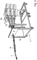
- Fig. 1
- eine perspektivische Ansicht der Bündelungsvorrichtung ohne Kabel und ohne Schlauch,
- Fig. 2
- eine weitere perspektivische Ansicht des Aufzieherteils der Bündelungsvorrichtung,
- Fig. 3
- eine schematische Darstellung eines von einem Schlauch umschlossenen Kabelbündels, und
- Fig. 4
- eine
Fig. 1 entsprechende Ansicht der Bündelungsvorrichtung mit Kabel und Schlauch. - Eine Bündelungsvorrichtung 1 für Kabel C, insbesondere für Datenkabel, weist einen ersten Montagerahmen 3 auf. Der erste Montagerahmen 3 hat beispielsweise einen rechteckigen Grundriss und weist eine Plattform oder eine geeignete Anzahl von Querstreben auf. Außerdem weist der erste Montagerahmen 3 vorliegend vier Transportrollen zum Bewegen auf. Von dem ersten Montagerahmen 3 stehen mehrere, zueinander parallele Träger 5 (senkrecht nach oben) ab. Zwei vorzugsweise am Rand des ersten Montagerahmens 3 angeordnete Träger 5 sind mittels einer Quertraverse 7 verbunden. Die beiden Träger 5 und die Quertraverse 7 bilden einen Rohrhalter 8. Die Quertraverse 7 weist (wenigstens näherungsweise mittig) eine Sammelöffnung 9 auf, die horizontal ausgerichtet ist.
- Ein Sammelrohr 11, welches ein festes und ein freies Ende aufweist, ist am Rohrhalter 8, genauer gesagt an der Quertraverse 7, mittels des festen Endes angebracht. Die Anbringung des Sammelrohrs 11 ist vorzugsweise für den Benutzer lösbar, so dass das Sammelrohr 11 gegen ein alternatives Sammelrohr mit anderem Durchmesser und/oder anderer Länge austauschbar ist. Das Sammelrohr 11 steht über den ersten Montagerahmen 3 über. Das hohle, zylindrische Sammelrohr 11 fluchtet mit der Sammelöffnung 9 und ist vorzugsweise horizontal ausgerichtet, steht also von der Quertraverse 7 horizontal ab. Die Ausrichtung des Sammelrohres 11 definiert eine Zufuhrrichtung z. Am freien Ende des Sammelrohres 11 ist ein Auschiebhilfel3 ("Entenschnabel") lösbar anbringbar, vorzugsweise in das hohle Sammelrohr 11 einsteckbar. Die Aufschiebhilfe 13 verjüngt sich (vorzugsweise konisch) von dem Durchmesser des Sammelrohres 11 zu eine kleinen, kugelförmigen Spitze. Auf der vom Sammelrohr 11 abgewandten Seite der Quertraverse 7 ist ein Sammelsieb 15 angebracht, welches mit der Sammelöffnung 9 fluchtet. Das Sammelsieb 15 ist in der Art eines Topfes mit mehreren Öffnungen im Boden ausgebildet. Auch die Anbringung des Sammelsiebs 15 ist vorzugsweise für den Benutzer lösbar, so dass das Sammelsieb 15 gegen ein alternatives Sammelsieb mit Öffnungen von anderem Durchmesser und/oder anderem Querschnitt und/oder andererAnzahl austauschbar ist.
- Zwei weitere Träger 5 lagern mehrere, vorliegend vier drehbare Führungsrollen 17, welche zwischen sich eine Führungsöffnung 19 bilden, die mit der Sammelöffnung 9 fluchtet, also in Zufuhrrichtung z ausgerichtet ist. Zwei Führungsrollen 17 sind horizontal, die beiden anderen vertikal angeordnet, so dass sich entsprechend der Anzahl der Führungsrollen 17 die Führungsöffnung 19 in rechteckiger Form ergibt. Mit einer anderen Anzahl von Führungsrollen 17 ergibt sich eine andere Form der Führungsöffnung 19. Die Führungsrollen 17 sind vorzugsweise hohle (oder massive) Rohre (von zylindrischer oder konischer Form), die an ihren Enden in Öffnungen von Lagern an den Trägern 5 greifen. Anstelle der Führungsrollen 19 könnte beispielsweise ein trichterförmiger Block aus einem besonders gleitenden Kunststoff verwenden werden. Ziel ist ein möglichst geringer Reibungswiderstand an der Begrenzung der Führungsöffnung 19. Der erste Montagerahmen 3 und seine Aufbauten bilden das Aufzieherteil der Bündelungsvorrichtung 1.
- Die Bündelungsvorrichtung 1 weist vorzugsweise einen zweiten Montagerahmen 21 auf. Die zweite Montagerahmen 21 weist beispielsweise einen rechteckigen Grundriss und vier Transportrollen zum Bewegen auf. Vorzugsweise sind die beiden Montagerahmen 3 und 21 unabhängig voneinander bewegbar, werden aber für den Gebrauch der Bündelungsvorrichtung 1 in Anlage aneinander gebracht ("andocken") und können gegebenenfalls auch verbunden werden. Von dem zweiten Montagerahmen 21 stehen weitere, zueinander parallele Träger 5 (senkrecht nach oben) ab. An den Trägern 5 des zweiten Montagerahmens 21 sind mehrere Abroller 23 montiert, welche zur Aufnahme von aufgewickelten Kabel C oder Trommeln mit aufgewickelten Kabeln C ausgebildet sind. Hierzu weisen die Abroller 23 eine vertikal nach oben offene Topfform mit einem zentralen Kern auf, welcher um eine vertikale Achse drehbar sein kann. Dadurch wird (im Gegensatz zu feststehenden Kabelzuführungen) eine Verwindung der Kabel C beim Abrollen verhindert. In der Wand des Abrollers 23 öffnet sich tangential eine Abrollöffnung 23a. Die Abroller 23 sind so montiert, dass die Abrollöffnung 23a in Zufuhrrichtung z (oder näherungsweise parallel dazu) ausgerichtet ist, wenn die beiden Montagerahmen 3 und 21 sich in Anlage aneinander befinden. Der zweite Montagerahmen 21 und seine Aufbauten bilden das Abrollerteil der Bündelungsvorrichtung 1.
- Mit der Bündelungsvorrichtung 1 können mehrere Kabel C zu einem Kabelbündel T zusammengefasst werden, welches von einem Schlauch H, insbesondere einem grobmaschigen Geflechtsschlauch (Netzschlauch) oder einem feinmaschigen Gewebeschlauch, umschlossen wird. Die Bündelungsvorrichtung 1 ist dabei als Aufziehvorrichtung ausgebildet, d.h. der Schlauch H wird mittels Zugkraft auf die gebündelten Kabel C aufgebracht. Das Verfahren hierzu umfasst drei Vorbereitungsschritte, mit denen die Bündelungsvorrichtung 1 vorbereitet (aufgerüstet) wird, und den Verarbeitungsschritt. Die Reihenfolge der drei Vorbereitungsschritte kann variieren, wobei die nachfolgend beschriebene Reihenfolge die bevorzugte ist.
- In einem ersten Vorbereitungsschritt wird die Aufschiebhilfe 13 in das Sammelrohr 11 gesteckt, der zu verwendete Schlauch H über die Aufschiebhilfe 13 auf das Sammelrohr 11 aufgeschoben (entgegen der Zufuhrrichtung z) und die Aufschiebhilfe 13 wieder entfernt. Der Schlauch H wirft beim Aufschieben Falten, so dass gegenüber der Länge des Sammelrohres 11 eine mehrfache Menge an Schlauch H aufschiebbar ist und damit gespeichert werden kann. Die Außenseite des Sammelrohrs 11 bildet nun eine Schlauchzufuhr 11a. Die Menge an Schlauch H ist auf die Länge herzustellenden, vom Schlauch H umschlossenen Kabelbündels T abgestimmt, d.h.. der Schlauch H wird vorher in einer passenden Länge abgelängt. Die Länge ergibt sich insbesondere aus den Parametern Bündeldurchmesser, Schlauchdurchmesser, Festigkeit des Schlauchs nach dem Aufziehen. In der Regel ist das Verhältnis Kabel C zu Schlauch H etwa 1,2:1, da der Schlauch H durch die nachfolgend beschriebene Straffung länger wird, wobei eine Toleranz der straffenden Zugkraft sich auf die tatsächlich benötigte Menge an Schlauch H auswirkt.
- In einem zweiten Vorbereitungsschritt werden die zu bündelnden Kabel C in die Abroller 23 eingelegt und das jeweils äußere Ende durch die Abrollöffnung 23a gefädelt. In einem dritten Vorbereitungsschritt, für den sich die beiden Montagerahmen 3 und 21 (und damit das Aufzieherteil und das Abrollerteil der Bündelungsvorrichtung 1) in Anlage aneinander befinden, wird von jedem Kabel C das Ende zunächst durch die Führungsöffnung 19 (als "grobe" Führung) und dann jeweils in genau eine Öffnung des Sammelsiebes 15 (als "feine" Führung) gesteckt, das zugeordnete Kabel C in Zufuhrrichtung z weitergeschoben (in der Regel zusammen mit den anderen zu bündelnden Kabeln C) durch die Sammelöffnung 9 und das Sammelrohr 11 (also die Kabelzufuhr 11i) hindurch bis zum Austritt aus dem nunmehr offenen, freien Ende des Sammelrohrs 11. Das Innere des Sammelrohres 11 bildet nun eine Kabelzufuhr 11i.
- Das Sammelsieb 15 positioniert die Kabel C bei der Einführung in das Sammelrohr 11, so dass sie beim Austritt aus dem Sammelrohr 11 die gewünschte Anordnung zueinander aufweisen. Das Sammelsieb 15 ist bezüglich des Durchmessers (beispielsweise Twisted-Pair 5 bis 8 mm, Lichtwellenleiter dünner), des Querschnitts (beispielsweise rund oder dreieckig) und der Anzahl (beispielsweise 12, 16, 24) seiner Öffnung an das herzustellende, vom Schlauch H umschlossene Kabelbündel T angepasst. Sofern die Anzahl der Abroller 23 des Abrollerteils der Bündelungsvorrichtung 1 nicht für die gewünschte Anzahl von Kabeln C ausreichen, wird ein weiteres Abrollerteil verwendet.
- Die freien Enden der zu bündelnden Kabel C werden ein Stück weiter aus der Kabelzufuhr 11i herausgezogen, so dass dieser herausragende Teil ("Peitsche") des Kabelbündels T (beispielsweise 0,5 m) frei vom Schlauch H bleibt. Zum Ende des dritten Vorbereitungsschritts wird das am freien Ende der Schlauchzufuhr 11a angeordnete Ende des Schlauchs H an dem aus der Kabelzufuhr 11i herausragenden Teil des Kabelbündels befestigt, beispielsweise mittels eines Klebeband provisiorisch angeklebt.
- Im Verarbeitungsschritt bildet das freie Ende des Sammelrohrs 11 die Bündelungsstelle 11e. Die Kabel C werden aus der Kabelzufuhr 11i gezogen (in Zufuhrrichtung z) und dabei zugleich der Schlauch H von der Schlauchzufuhr 11a abgezogen (ebenfalls in Zufuhrrichtung z), beispielsweise manuell oder mittels eines Greifers oder mittels eines elektrisch angetriebenen Kabelaufrollers, so dass an der Bündelungsstelle 11e gemeinsam das vom Schlauch H umschlossene Kabelbündel T entsteht und in Verlängerung der Zufuhrrichtung z abgegeben wird. Die Führungsrollen 17 und das Sammelsieb 15 sorgen für eine gleichmäßige und reibungsarme Versorgung der Kabelzufuhr 11i mit weiterem Kabel. Die Zugkraft am Schlauch H (welche mittels der Befestigung am Kabelbündel T und den bereits das Kabelbündel T umschließenden Teil des Schlauchs H auf den Schlauch H am freien Ende der Schlauchzufuhr 11a übertragen wird) sorgt dafür, dass sich der Schlauch H eng an das Kabelbündel T anlegt. Gegebenenfalls ist auch eine Einrichtung vorgesehen, welche den Schlauch H mit der richtigen Spannung von der Schlauchzufuhr 11a abgibt, sofern diese Regelung nicht manuell erfolgt.
- In einem späteren Verfahrensschritt können die Klebestellen an den Enden des Schlauchs H durch einen elastischen Gummischlauch oder einen Schrumpfschlauch (oder eine sonstige Manschette) gesichert oder ersetzt werden. Ferner können Stecker, beispielsweise RJ45, an den jeweiligen Enden der Kabel C angebracht werden, um ein Bündel konfektionierter Datenkabel ("Patch Cord" oder kurz "Cord") zu erhalten.
- Vorliegend sind das Abrollerteil und das Aufzieherteil der Bündelungsvorrichtung 1 nicht miteinander verbunden. Dadurch kann wenigstens ein weiteres Abrollerteil zum Einsatz kommen, d.h. ein weiterer zweiter Montagerahmen 21 samt Aufbauten. Die Abrollerteile werden vorab mit den zu bündelnden Kabeln C bestückt, beispielsweise als Nachschub für den nächsten Bündelungsvorgang oder für eine andere Farbkodierung. Das Bestücken kann beispielsweise direkt nach der Ablängmaschine erfolgen. Das benutzte Abrollerteil kann dann nach dem Verarbeitungsschritt durch das vorbereitete, weitere Abrollerteil ersetzt werden und an das Aufzieherteil andocken, um ohne nennenswerten Zeitverlust weiter bündeln zu können, d.h. die Rüstzeiten der Bündelungsvorrichtung 1 werden verkürzt, insbesondere beim zweiten Vorbereitungsschritt. An das Andocken schließt sich wieder der dritter Vorbereitungsschritt an.
-
- 1
- Bündelungsvorrichtung
- 3
- erster Montagerahmen
- 5
- Träger
- 7
- Quertraverse
- 8
- Rohrhalter
- 9
- Sammelöffnung
- 11
- Sammelrohr
- 11a
- Schlauchzufuhr
- 11e
- Bündelungsstelle
- 11i
- Kabelzufuhr
- 13
- Aufschiebhilfe
- 15
- Sammelsieb
- 17
- Führungsrolle
- 19
- Führungsöffnung
- 21
- zweiter Montagerahmen
- 23
- Abroller
- 23a
- Abrollöffnung
- C
- Kabel
- H
- Schlauch
- T
- Kabelbündel, vom Schlauch umschlossen
- z
- Zufuhrrichtung
Claims (12)
- Bündelungsvorrichtung (1) für Kabel, mita) wenigstens einer Kabelzufuhr (11i), welche mehrere, zu bündelnde Kabel (C) in einer Zufuhrrichtung (z) zuführt,b) einer Schlauchzufuhr (11a), welche einen Schlauch (H) zuführt,c) einer Bündelungsstelle (11e), ab welcher der Schlauch (H) das Kabelbündel (T) umschließt,d) einem hohlen Sammelrohr (11), dessen Inneres die Kabelzufuhr (11i) und dessen Außenseite die Schlauchzufuhr (11a) bildet, wobei ein freies Ende des Sammelrohres (11), welches in Zufuhrrichtung nach der Kabelzufuhr (11i) angeordnet ist, die Bündelungsstelle (11e) bildet, und wobei das Sammelrohr (11) auf der vom freien Ende abgewandten Seite ein festes Ende aufweist, welches an einem Rohrhalter (8) befestigt ist und welches in Zufuhrrichtung (z) vor der Kabelzufuhr (11i) angeordnet ist,e) einer Sammelöffnung (9), welche im Rohrhalter (8) ausgebildet ist, mit welcher das Sammelrohr (11) fluchtet, welche in Zufuhrrichtung (z) vor der Kabelzufuhr (11i) angeordnet ist und durch welche die zu bündelnden Kabel (C) gemeinsam geführt sind, undf) einem Abroller (23) für jedes zu bündelnde Kabel (C), welcher das Kabel (C) abgibt,
gekennzeichnet durchg) ein Sammelsieb (15) mit mehreren Öffnungen, welches am Rohrhalter (8) befestigt ist, mit welchem das Sammelrohr (11) fluchtet, welches in Zufuhrrichtung (z) vor der Kabelzufuhr (11i) angeordnet ist und durch welches - als feine Führung - die zu bündelnden Kabel (C) durch jeweils genau eine Öffnung einzeln geführt sind, undh) eine Führungsöffnung (19), welche zwischen den Abrollern (23) und dem festen Ende des Sammelrohrs (11) mit der Sammelöffnung (9) und dem Sammelsieb (15) in Zufuhrrichtung (z) vor der Kabelzufuhr (11i) vorgesehen ist und durch welche - als grobe Führung - jedes der zu bündelnden Kabel (C) geführt ist. - Bündelungsvorrichtung nach Anspruch 1, gekennzeichnet durch einen ersten Montagerahmen (3), von dem mehrere Träger (5) abstehen, wobei zwei Träger (5) zusammen mit einer Quertraverse (7) den Rohrhalter (8) bilden, und zwei weitere Träger (5) mehrere Führungsrollen (17), welche zwischen sich die Führungsöffnung (19) bilden, wobei der erste Montagerahmen (3) und seine Aufbauten ein Aufzieherteil der Bündelungsvorrichtung (1) bilden.
- Bündelungsvorrichtung nach Anspruch 1 oder 2, gekennzeichnet durch einen zweiten Montagerahmen (21), von dem weitere Träger (5) abstehen, an denen die vorgesehenen Abroller (23) montiert sind, wobei der zweite Montagerahmen (21) und seine Aufbauten ein Abrollerteil der Bündelungsvorrichtung (1) bilden.
- Bündelungsvorrichtung nach Anspruch 2 und 3, dadurch gekennzeichnet, dass die beiden Montagerahmen (3, 21) unabhängig voneinander bewegbar und für den Gebrauch der Bündelungsvorrichtung (1) in Anlage aneinander bringbar sind.
- Bündelungsvorrichtung nach Anspruch 3 oder 4, dadurch gekennzeichnet, dass ein weiteres Abrollerteil vorgesehen ist.
- Bündelungsvorrichtung nach einem der vorhergehenden Ansprüche, dadurch gekennzeichnet, dass die Bündelungsvorrichtung (1) eine Aufschiebhilfe (13) zum erleichterten Aufschieben des Schlauchs (H) auf die Schlauchzufuhr (11a) aufweist, wobei die Aufschiebhilfe (13) lösbar am Sammelrohr (11) anbringbar ist, insbesondere in das Sammelrohr (11) einsteckbar ist.
- Bündelungsvorrichtung nach einem der vorhergehenden Ansprüche, dadurch gekennzeichnet, dass das Sammelrohr (11) und/oder das Sammelsieb (15) austauschbar am Rohrhalter (8) befestigt sind.
- Verfahren zum Bündeln von Kabeln mittels einer Bündelungsvorrichtung nach einem der vorhergehenden Ansprüche, wobei in einem Verarbeitungsschritt die zu bündelnden Kabel (C) die zu bündelnden Kabel (C) von den Abrollern (23) der Bündelungsvorrichtung (1) abgerollt, durch die Führungsöffnung (19) und das Sammelsieb (15) und die Sammelöffnung (9) im Rohrhalter (8) der Kabelzufuhr (11i) zugeführt und mittels der Kabelzufuhr (11i) in der Zufuhrrichtung (z) der Bündelungsstelle (11e) zugeführt werden, während der Schlauch (H) mittels der Schlauchzufuhr (11a) der Bündelungsstelle (11e) zugeführt wird, und in Zufuhrrichtung (z) nach der Bündelungsstelle (11e) das vom Schlauch (H) umschlossene Kabelbündel (T) abgegeben wird.
- Verfahren nach Anspruch 8, dadurch gekennzeichnet, das die Schlauchzufuhr (11a) den Schlauch (H) in der Zufuhrrichtung (z) der Bündelungsstelle (11e) zuführt.
- Verfahren nach Anspruch 8 oder 9, dadurch gekennzeichnet, dass in einem Vorbereitungsschritt die Aufschiebhilfe (13) am freien Ende des Sammelrohres (11) angebracht wird, der Schlauch (H) auf die Schlauchzufuhr (11a) aufgeschoben wird, und die Aufschiebhilfe (13) wieder vom Sammelrohr (11) getrennt wird.
- Verfahren nach einem der Ansprüche 8 bis 10, dadurch gekennzeichnet, dass nach dem Verarbeitungsschritt das benutzte Abrollerteil durch das vorbereitete, weitere Abrollerteil ersetzt wird und an das Aufzieherteil andockt.
- Verfahren nach einem der Ansprüche 8 bis 11, dadurch gekennzeichnet, dass das Sammelrohr (11) gegen ein alternatives Sammelrohr mit anderem Durchmesser und/oder anderer Länge ausgetauscht wird, und/oder dass das Sammelsieb (15) gegen ein alternatives Sammelsieb mit Öffnungen von anderem Durchmesser und/oder anderem Querschnitt und/oder andererAnzahl ausgetauscht wird.
Priority Applications (2)
| Application Number | Priority Date | Filing Date | Title |
|---|---|---|---|
| HUE14002545A HUE037697T2 (hu) | 2014-07-23 | 2014-07-23 | Kötegelõberendezés kábelek számára és eljárás kábelek kötegelésére |
| EP14002545.3A EP2978087B1 (de) | 2014-07-23 | 2014-07-23 | Bündelungsvorrichtung für Kabel und Verfahren zum Bündeln von Kabeln |
Applications Claiming Priority (1)
| Application Number | Priority Date | Filing Date | Title |
|---|---|---|---|
| EP14002545.3A EP2978087B1 (de) | 2014-07-23 | 2014-07-23 | Bündelungsvorrichtung für Kabel und Verfahren zum Bündeln von Kabeln |
Publications (2)
| Publication Number | Publication Date |
|---|---|
| EP2978087A1 EP2978087A1 (de) | 2016-01-27 |
| EP2978087B1 true EP2978087B1 (de) | 2017-09-06 |
Family
ID=51263173
Family Applications (1)
| Application Number | Title | Priority Date | Filing Date |
|---|---|---|---|
| EP14002545.3A Active EP2978087B1 (de) | 2014-07-23 | 2014-07-23 | Bündelungsvorrichtung für Kabel und Verfahren zum Bündeln von Kabeln |
Country Status (2)
| Country | Link |
|---|---|
| EP (1) | EP2978087B1 (de) |
| HU (1) | HUE037697T2 (de) |
Families Citing this family (2)
| Publication number | Priority date | Publication date | Assignee | Title |
|---|---|---|---|---|
| CN109677992B (zh) * | 2018-12-21 | 2023-11-17 | 中国信息通信研究院 | 一种用于串音测试的样品制作系统 |
| DE102022130323A1 (de) | 2022-11-16 | 2024-05-16 | Kromberg & Schubert Automotive Gmbh & Co. Kg | Vorrichtung und Verfahren zum Zusammenführen mehrerer Leitungen zu einer Verarbeitungsvorrichtung |
Family Cites Families (5)
| Publication number | Priority date | Publication date | Assignee | Title |
|---|---|---|---|---|
| IT1203719B (it) * | 1983-12-27 | 1989-02-23 | Pirelli Cavi Spa | Procedimento e dispositivo per realizzare giunti per cavi |
| US6267355B1 (en) * | 1999-06-15 | 2001-07-31 | Douglas D. Fletcher | Cable installing method and apparatus |
| US7433571B2 (en) * | 2005-09-08 | 2008-10-07 | David Kendricks | Cable bundling and organizing system |
| US7861501B2 (en) * | 2008-05-10 | 2011-01-04 | Btx Technologies, Inc. | Method and apparatus for applying flexible sleeving |
| US8322690B2 (en) * | 2009-02-25 | 2012-12-04 | Matthew Cathlina | Cable dressing fixture |
-
2014
- 2014-07-23 EP EP14002545.3A patent/EP2978087B1/de active Active
- 2014-07-23 HU HUE14002545A patent/HUE037697T2/hu unknown
Non-Patent Citations (1)
| Title |
|---|
| None * |
Also Published As
| Publication number | Publication date |
|---|---|
| HUE037697T2 (hu) | 2018-09-28 |
| EP2978087A1 (de) | 2016-01-27 |
Similar Documents
| Publication | Publication Date | Title |
|---|---|---|
| DE69318291T3 (de) | Verfahren und einrichtung zur herstellung eines verbindungskabels | |
| DE102017109819B4 (de) | Umwickeln eines Leitungssatzes mit Band | |
| DE4205574C2 (de) | Kanalkörper und Verfahren zum Verlegen eines Kabels in diesem | |
| DE3320250A1 (de) | Verfahren zum weiterverarbeiten von mit hilfe eines flyers aufgewickeltem strangfoermigen gut | |
| DE102014100426B4 (de) | Wickeldorn | |
| EP2978087B1 (de) | Bündelungsvorrichtung für Kabel und Verfahren zum Bündeln von Kabeln | |
| EP0368801B1 (de) | Verfahren und Vorrichtung zur Fadenteilung an einer Schärmaschine | |
| DE102011015060A1 (de) | Vorrichtung und Verfahren zum Herstellen von Rundbürsten | |
| DE102016119983A1 (de) | Pneumatisches Fadenspeicherorgan, Arbeitsstelle einer Textilmaschine mit einem Fadenspeicherorgan und Textilmaschine mit einer Vielzahl von Arbeitsstellen mit einem Fadenspeicherorgan | |
| WO2016150632A1 (de) | Verfahren und vorrichtung zur herstellung eines rohrverbundes aus kabelrohren | |
| DD207854A5 (de) | Verfahren und vorrichtung zur herstellung von borstenbuendeln und einzelborsten aus kunststoff | |
| CH683809A5 (de) | Verfahren und Einrichtung zum Ablängen und Abisolieren ummantelter Kabel. | |
| EP0842716B1 (de) | Vorrichtung zur Herstellung von Metallröhrchen grosser Länge | |
| DE2946248A1 (de) | Verfahren und vorrichtung zur kontinuierlichen verseilung von adern groesseren querschnitts fuer elektrische kabel | |
| DE102017110535B4 (de) | Verfahren zur Handhabung von Geflechtschläuchen sowie Vorrichtung zur Handhabung von Geflechtschläuchen | |
| EP0437709B1 (de) | Langgestrecktes Element zum Einziehen in ein Rohr und Verfahren zur Anwendung hierfür | |
| EP3000340B1 (de) | Fadenzuführvorrichtung | |
| EP1562845B1 (de) | Mehrfach-wickelmaschine | |
| WO2019076562A1 (de) | Kabelsammler | |
| DE102012219578A1 (de) | Faserlegemaschine zum gleichzeitigen Verlegen und Vernähen mehrerer Faserstränge | |
| WO1993020903A1 (de) | Verfahren zum herstellen einer bespannungssaite in lieferform für ballschläger, insbesondere tennisschläger | |
| DE102015220693B4 (de) | Vorrichtung zum Legen eines biegeschlaffen, strangförmigen Elements und Verfahren dazu | |
| WO1991000537A1 (de) | Verfahren und einrichtung zum einziehen von insbesondere lichtwellenleiterkabeln in schutzrohre | |
| WO1988007279A1 (en) | Device for subsequent insertion of cables into cable ducts | |
| DE102004018361B3 (de) | Hohlgeflechtschlauch aus rundgeflochtenen Litzen sowie Verfahren zum Herstellen eines solchen Hohlgeflechtschlauchs |
Legal Events
| Date | Code | Title | Description |
|---|---|---|---|
| PUAI | Public reference made under article 153(3) epc to a published international application that has entered the european phase |
Free format text: ORIGINAL CODE: 0009012 |
|
| 17P | Request for examination filed |
Effective date: 20150905 |
|
| AK | Designated contracting states |
Kind code of ref document: A1 Designated state(s): AL AT BE BG CH CY CZ DE DK EE ES FI FR GB GR HR HU IE IS IT LI LT LU LV MC MK MT NL NO PL PT RO RS SE SI SK SM TR |
|
| AX | Request for extension of the european patent |
Extension state: BA ME |
|
| GRAP | Despatch of communication of intention to grant a patent |
Free format text: ORIGINAL CODE: EPIDOSNIGR1 |
|
| RIC1 | Information provided on ipc code assigned before grant |
Ipc: H02G 1/06 20060101AFI20170411BHEP Ipc: H02G 3/04 20060101ALI20170411BHEP Ipc: H02G 1/08 20060101ALI20170411BHEP |
|
| INTG | Intention to grant announced |
Effective date: 20170508 |
|
| GRAS | Grant fee paid |
Free format text: ORIGINAL CODE: EPIDOSNIGR3 |
|
| GRAA | (expected) grant |
Free format text: ORIGINAL CODE: 0009210 |
|
| AK | Designated contracting states |
Kind code of ref document: B1 Designated state(s): AL AT BE BG CH CY CZ DE DK EE ES FI FR GB GR HR HU IE IS IT LI LT LU LV MC MK MT NL NO PL PT RO RS SE SI SK SM TR |
|
| REG | Reference to a national code |
Ref country code: GB Ref legal event code: FG4D Free format text: NOT ENGLISH |
|
| REG | Reference to a national code |
Ref country code: CH Ref legal event code: EP Ref country code: AT Ref legal event code: REF Ref document number: 926855 Country of ref document: AT Kind code of ref document: T Effective date: 20170915 |
|
| REG | Reference to a national code |
Ref country code: IE Ref legal event code: FG4D Free format text: LANGUAGE OF EP DOCUMENT: GERMAN |
|
| REG | Reference to a national code |
Ref country code: DE Ref legal event code: R096 Ref document number: 502014005289 Country of ref document: DE |
|
| REG | Reference to a national code |
Ref country code: NL Ref legal event code: MP Effective date: 20170906 |
|
| REG | Reference to a national code |
Ref country code: LT Ref legal event code: MG4D |
|
| PG25 | Lapsed in a contracting state [announced via postgrant information from national office to epo] |
Ref country code: HR Free format text: LAPSE BECAUSE OF FAILURE TO SUBMIT A TRANSLATION OF THE DESCRIPTION OR TO PAY THE FEE WITHIN THE PRESCRIBED TIME-LIMIT Effective date: 20170906 Ref country code: SE Free format text: LAPSE BECAUSE OF FAILURE TO SUBMIT A TRANSLATION OF THE DESCRIPTION OR TO PAY THE FEE WITHIN THE PRESCRIBED TIME-LIMIT Effective date: 20170906 Ref country code: NO Free format text: LAPSE BECAUSE OF FAILURE TO SUBMIT A TRANSLATION OF THE DESCRIPTION OR TO PAY THE FEE WITHIN THE PRESCRIBED TIME-LIMIT Effective date: 20171206 Ref country code: LT Free format text: LAPSE BECAUSE OF FAILURE TO SUBMIT A TRANSLATION OF THE DESCRIPTION OR TO PAY THE FEE WITHIN THE PRESCRIBED TIME-LIMIT Effective date: 20170906 Ref country code: FI Free format text: LAPSE BECAUSE OF FAILURE TO SUBMIT A TRANSLATION OF THE DESCRIPTION OR TO PAY THE FEE WITHIN THE PRESCRIBED TIME-LIMIT Effective date: 20170906 |
|
| PG25 | Lapsed in a contracting state [announced via postgrant information from national office to epo] |
Ref country code: LV Free format text: LAPSE BECAUSE OF FAILURE TO SUBMIT A TRANSLATION OF THE DESCRIPTION OR TO PAY THE FEE WITHIN THE PRESCRIBED TIME-LIMIT Effective date: 20170906 Ref country code: BG Free format text: LAPSE BECAUSE OF FAILURE TO SUBMIT A TRANSLATION OF THE DESCRIPTION OR TO PAY THE FEE WITHIN THE PRESCRIBED TIME-LIMIT Effective date: 20171206 Ref country code: ES Free format text: LAPSE BECAUSE OF FAILURE TO SUBMIT A TRANSLATION OF THE DESCRIPTION OR TO PAY THE FEE WITHIN THE PRESCRIBED TIME-LIMIT Effective date: 20170906 Ref country code: RS Free format text: LAPSE BECAUSE OF FAILURE TO SUBMIT A TRANSLATION OF THE DESCRIPTION OR TO PAY THE FEE WITHIN THE PRESCRIBED TIME-LIMIT Effective date: 20170906 Ref country code: GR Free format text: LAPSE BECAUSE OF FAILURE TO SUBMIT A TRANSLATION OF THE DESCRIPTION OR TO PAY THE FEE WITHIN THE PRESCRIBED TIME-LIMIT Effective date: 20171207 |
|
| PG25 | Lapsed in a contracting state [announced via postgrant information from national office to epo] |
Ref country code: NL Free format text: LAPSE BECAUSE OF FAILURE TO SUBMIT A TRANSLATION OF THE DESCRIPTION OR TO PAY THE FEE WITHIN THE PRESCRIBED TIME-LIMIT Effective date: 20170906 |
|
| PG25 | Lapsed in a contracting state [announced via postgrant information from national office to epo] |
Ref country code: RO Free format text: LAPSE BECAUSE OF FAILURE TO SUBMIT A TRANSLATION OF THE DESCRIPTION OR TO PAY THE FEE WITHIN THE PRESCRIBED TIME-LIMIT Effective date: 20170906 Ref country code: PL Free format text: LAPSE BECAUSE OF FAILURE TO SUBMIT A TRANSLATION OF THE DESCRIPTION OR TO PAY THE FEE WITHIN THE PRESCRIBED TIME-LIMIT Effective date: 20170906 Ref country code: CZ Free format text: LAPSE BECAUSE OF FAILURE TO SUBMIT A TRANSLATION OF THE DESCRIPTION OR TO PAY THE FEE WITHIN THE PRESCRIBED TIME-LIMIT Effective date: 20170906 |
|
| PG25 | Lapsed in a contracting state [announced via postgrant information from national office to epo] |
Ref country code: EE Free format text: LAPSE BECAUSE OF FAILURE TO SUBMIT A TRANSLATION OF THE DESCRIPTION OR TO PAY THE FEE WITHIN THE PRESCRIBED TIME-LIMIT Effective date: 20170906 Ref country code: SK Free format text: LAPSE BECAUSE OF FAILURE TO SUBMIT A TRANSLATION OF THE DESCRIPTION OR TO PAY THE FEE WITHIN THE PRESCRIBED TIME-LIMIT Effective date: 20170906 Ref country code: IS Free format text: LAPSE BECAUSE OF FAILURE TO SUBMIT A TRANSLATION OF THE DESCRIPTION OR TO PAY THE FEE WITHIN THE PRESCRIBED TIME-LIMIT Effective date: 20180106 Ref country code: IT Free format text: LAPSE BECAUSE OF FAILURE TO SUBMIT A TRANSLATION OF THE DESCRIPTION OR TO PAY THE FEE WITHIN THE PRESCRIBED TIME-LIMIT Effective date: 20170906 Ref country code: SM Free format text: LAPSE BECAUSE OF FAILURE TO SUBMIT A TRANSLATION OF THE DESCRIPTION OR TO PAY THE FEE WITHIN THE PRESCRIBED TIME-LIMIT Effective date: 20170906 |
|
| REG | Reference to a national code |
Ref country code: DE Ref legal event code: R097 Ref document number: 502014005289 Country of ref document: DE |
|
| PLBE | No opposition filed within time limit |
Free format text: ORIGINAL CODE: 0009261 |
|
| STAA | Information on the status of an ep patent application or granted ep patent |
Free format text: STATUS: NO OPPOSITION FILED WITHIN TIME LIMIT |
|
| PG25 | Lapsed in a contracting state [announced via postgrant information from national office to epo] |
Ref country code: DK Free format text: LAPSE BECAUSE OF FAILURE TO SUBMIT A TRANSLATION OF THE DESCRIPTION OR TO PAY THE FEE WITHIN THE PRESCRIBED TIME-LIMIT Effective date: 20170906 |
|
| 26N | No opposition filed |
Effective date: 20180607 |
|
| PG25 | Lapsed in a contracting state [announced via postgrant information from national office to epo] |
Ref country code: SI Free format text: LAPSE BECAUSE OF FAILURE TO SUBMIT A TRANSLATION OF THE DESCRIPTION OR TO PAY THE FEE WITHIN THE PRESCRIBED TIME-LIMIT Effective date: 20170906 |
|
| PG25 | Lapsed in a contracting state [announced via postgrant information from national office to epo] |
Ref country code: MT Free format text: LAPSE BECAUSE OF FAILURE TO SUBMIT A TRANSLATION OF THE DESCRIPTION OR TO PAY THE FEE WITHIN THE PRESCRIBED TIME-LIMIT Effective date: 20170906 |
|
| REG | Reference to a national code |
Ref country code: HU Ref legal event code: AG4A Ref document number: E037697 Country of ref document: HU |
|
| REG | Reference to a national code |
Ref country code: CH Ref legal event code: PL |
|
| GBPC | Gb: european patent ceased through non-payment of renewal fee |
Effective date: 20180723 |
|
| PG25 | Lapsed in a contracting state [announced via postgrant information from national office to epo] |
Ref country code: LU Free format text: LAPSE BECAUSE OF NON-PAYMENT OF DUE FEES Effective date: 20180723 Ref country code: MC Free format text: LAPSE BECAUSE OF FAILURE TO SUBMIT A TRANSLATION OF THE DESCRIPTION OR TO PAY THE FEE WITHIN THE PRESCRIBED TIME-LIMIT Effective date: 20170906 |
|
| REG | Reference to a national code |
Ref country code: BE Ref legal event code: MM Effective date: 20180731 |
|
| REG | Reference to a national code |
Ref country code: IE Ref legal event code: MM4A |
|
| PG25 | Lapsed in a contracting state [announced via postgrant information from national office to epo] |
Ref country code: FR Free format text: LAPSE BECAUSE OF NON-PAYMENT OF DUE FEES Effective date: 20180731 Ref country code: GB Free format text: LAPSE BECAUSE OF NON-PAYMENT OF DUE FEES Effective date: 20180723 Ref country code: CH Free format text: LAPSE BECAUSE OF NON-PAYMENT OF DUE FEES Effective date: 20180731 Ref country code: IE Free format text: LAPSE BECAUSE OF NON-PAYMENT OF DUE FEES Effective date: 20180723 Ref country code: LI Free format text: LAPSE BECAUSE OF NON-PAYMENT OF DUE FEES Effective date: 20180731 |
|
| PG25 | Lapsed in a contracting state [announced via postgrant information from national office to epo] |
Ref country code: BE Free format text: LAPSE BECAUSE OF NON-PAYMENT OF DUE FEES Effective date: 20180731 |
|
| PG25 | Lapsed in a contracting state [announced via postgrant information from national office to epo] |
Ref country code: TR Free format text: LAPSE BECAUSE OF FAILURE TO SUBMIT A TRANSLATION OF THE DESCRIPTION OR TO PAY THE FEE WITHIN THE PRESCRIBED TIME-LIMIT Effective date: 20170906 |
|
| PG25 | Lapsed in a contracting state [announced via postgrant information from national office to epo] |
Ref country code: PT Free format text: LAPSE BECAUSE OF FAILURE TO SUBMIT A TRANSLATION OF THE DESCRIPTION OR TO PAY THE FEE WITHIN THE PRESCRIBED TIME-LIMIT Effective date: 20170906 |
|
| PG25 | Lapsed in a contracting state [announced via postgrant information from national office to epo] |
Ref country code: CY Free format text: LAPSE BECAUSE OF FAILURE TO SUBMIT A TRANSLATION OF THE DESCRIPTION OR TO PAY THE FEE WITHIN THE PRESCRIBED TIME-LIMIT Effective date: 20170906 Ref country code: MK Free format text: LAPSE BECAUSE OF NON-PAYMENT OF DUE FEES Effective date: 20170906 |
|
| PG25 | Lapsed in a contracting state [announced via postgrant information from national office to epo] |
Ref country code: AL Free format text: LAPSE BECAUSE OF FAILURE TO SUBMIT A TRANSLATION OF THE DESCRIPTION OR TO PAY THE FEE WITHIN THE PRESCRIBED TIME-LIMIT Effective date: 20170906 |
|
| REG | Reference to a national code |
Ref country code: DE Ref legal event code: R082 Ref document number: 502014005289 Country of ref document: DE Representative=s name: LANGPATENT ANWALTSKANZLEI IP LAW FIRM, DE Ref country code: AT Ref legal event code: MM01 Ref document number: 926855 Country of ref document: AT Kind code of ref document: T Effective date: 20190723 Ref country code: DE Ref legal event code: R082 Ref document number: 502014005289 Country of ref document: DE Representative=s name: JONES DAY RECHTSANWAELTE PATENTANWAELTE, DE Ref country code: DE Ref legal event code: R081 Ref document number: 502014005289 Country of ref document: DE Owner name: SINBON ELECTRONICS CO. LTD., TW Free format text: FORMER OWNER: KOVACS, TIBOR, 84347 PFARRKIRCHEN, DE |
|
| REG | Reference to a national code |
Ref country code: HU Ref legal event code: GB9C Owner name: SINBON ELECTRONICS CO. LTD., TW Free format text: FORMER OWNER(S): KOVACS, TIBOR, DE |
|
| PG25 | Lapsed in a contracting state [announced via postgrant information from national office to epo] |
Ref country code: AT Free format text: LAPSE BECAUSE OF NON-PAYMENT OF DUE FEES Effective date: 20190723 |
|
| REG | Reference to a national code |
Ref country code: DE Ref legal event code: R082 Ref document number: 502014005289 Country of ref document: DE Representative=s name: LANGPATENT ANWALTSKANZLEI IP LAW FIRM, DE |
|
| PGFP | Annual fee paid to national office [announced via postgrant information from national office to epo] |
Ref country code: HU Payment date: 20230619 Year of fee payment: 10 Ref country code: DE Payment date: 20230619 Year of fee payment: 10 |