EP2978007A1 - Commutateur thermosensible avec film isolant - Google Patents
Commutateur thermosensible avec film isolant Download PDFInfo
- Publication number
- EP2978007A1 EP2978007A1 EP15176424.8A EP15176424A EP2978007A1 EP 2978007 A1 EP2978007 A1 EP 2978007A1 EP 15176424 A EP15176424 A EP 15176424A EP 2978007 A1 EP2978007 A1 EP 2978007A1
- Authority
- EP
- European Patent Office
- Prior art keywords
- cover part
- switch according
- insulating film
- wall
- inner diameter
- Prior art date
- Legal status (The legal status is an assumption and is not a legal conclusion. Google has not performed a legal analysis and makes no representation as to the accuracy of the status listed.)
- Withdrawn
Links
Images


Classifications
-
- H—ELECTRICITY
- H01—ELECTRIC ELEMENTS
- H01H—ELECTRIC SWITCHES; RELAYS; SELECTORS; EMERGENCY PROTECTIVE DEVICES
- H01H37/00—Thermally-actuated switches
- H01H37/02—Details
- H01H37/04—Bases; Housings; Mountings
-
- H—ELECTRICITY
- H01—ELECTRIC ELEMENTS
- H01H—ELECTRIC SWITCHES; RELAYS; SELECTORS; EMERGENCY PROTECTIVE DEVICES
- H01H37/00—Thermally-actuated switches
- H01H37/02—Details
-
- H—ELECTRICITY
- H01—ELECTRIC ELEMENTS
- H01H—ELECTRIC SWITCHES; RELAYS; SELECTORS; EMERGENCY PROTECTIVE DEVICES
- H01H37/00—Thermally-actuated switches
- H01H37/02—Details
- H01H37/32—Thermally-sensitive members
- H01H37/52—Thermally-sensitive members actuated due to deflection of bimetallic element
- H01H37/54—Thermally-sensitive members actuated due to deflection of bimetallic element wherein the bimetallic element is inherently snap acting
- H01H37/5427—Thermally-sensitive members actuated due to deflection of bimetallic element wherein the bimetallic element is inherently snap acting encapsulated in sealed miniaturised housing
-
- H—ELECTRICITY
- H01—ELECTRIC ELEMENTS
- H01H—ELECTRIC SWITCHES; RELAYS; SELECTORS; EMERGENCY PROTECTIVE DEVICES
- H01H37/00—Thermally-actuated switches
- H01H37/02—Details
- H01H37/32—Thermally-sensitive members
- H01H37/52—Thermally-sensitive members actuated due to deflection of bimetallic element
-
- H—ELECTRICITY
- H01—ELECTRIC ELEMENTS
- H01H—ELECTRIC SWITCHES; RELAYS; SELECTORS; EMERGENCY PROTECTIVE DEVICES
- H01H37/00—Thermally-actuated switches
- H01H37/02—Details
- H01H37/60—Means for producing snap action
-
- H—ELECTRICITY
- H01—ELECTRIC ELEMENTS
- H01H—ELECTRIC SWITCHES; RELAYS; SELECTORS; EMERGENCY PROTECTIVE DEVICES
- H01H2205/00—Movable contacts
- H01H2205/002—Movable contacts fixed to operating part
Definitions
- the present invention relates to a temperature-dependent switch with a housing having a lid part with an upper side and a lower part with an inner circumferential shoulder and a wall above the shoulder circumferential wall, which has an inner side above the shoulder, wherein disposed between the lower part and the cover part an insulating film is, which extends with its edge region to the top of the lid part, and the wall of the lower part is bent over to the top and thereby holds the cover part with the interposition of the insulating film on the peripheral shoulder in the lower part, and arranged in the housing with a temperature-dependent Derailleur, which produces or opens an electrically conductive connection between two externally provided on the housing contact surfaces as a function of its temperature.
- Such a switch is from the DE 196 23 570 A1 known.
- the known temperature-dependent switch is used in a conventional manner to monitor the temperature of a device. For this purpose, for example, it is brought into thermal contact with the device to be protected via one of its outer surfaces, so that the temperature of the device to be protected influences the temperature of the derailleur.
- the switch is electrically connected via the soldered to its outer contact pads leads in series in the supply circuit of the device to be protected, so that below the response temperature of the switch, the supply current of the device to be protected flows through the switch.
- the known switch has a deep-drawn lower part, in which an inner circumferential shoulder is provided, on which a lid part rests.
- the lid part is held by a raised and flanged edge of the base firmly on this shoulder.
- cover part and lower part are made of electrically conductive material, between them an insulating film is provided which extends parallel to the cover part and is pulled up laterally, so that its edge region extends to the top of the cover part.
- the flanged edge, so the bent wall of the lower part presses with the interposition of the insulating film on the cover part, so that the insulating film between the edge and the upper part and the peripheral shoulder and the inside of the cover part is clamped.
- the temperature-dependent switching mechanism here comprises a spring snap-action disk, which carries the movable contact part, as well as a bimetallic disk which is put over the movable contact part.
- the spring snap-action disc presses the movable contact part against a stationary counter contact on the inside of the cover part.
- the spring snap-action disc With its edge, the spring snap-action disc is supported in the lower part of the housing, so that the electric current flows from the lower part through the spring snap-action disc and the movable contact part into the stationary counter-contact and from there into the cover part.
- the first external connection is a contact surface, which is arranged centrally on the cover part.
- This design is particularly chosen when very high currents must be switched, which can not be easily passed through the spring washer itself.
- a bimetal disc is provided for the temperature-dependent switching function, which rests below its critical temperature without force in the switching mechanism, wherein it is arranged geometrically between the contact part or the contact bridge and the spring snap-action disc.
- a bimetal part is understood as meaning a multilayer, active, sheet-metal component made of two, three or four components with different coefficients of expansion that are inseparably connected to one another.
- the connection of the individual layers of metals or metal alloys are cohesively or positively and are achieved for example by rolling.
- bimetallic parts In their low-temperature position, such bimetallic parts have a first and their high-temperature position have a second stable geometric conformation, between which they change over in a temperature-dependent manner in the manner of a hysteresis. When the temperature changes beyond its response temperature or below its return temperature, the bimetal parts snap over into the other conformation.
- the bimetal parts are therefore often referred to as snap disks, wherein they can have an elongated, oval or circular shape in plan view.
- the bimetallic disc changes its configuration and works against the spring snap-action disc, that they are the movable contact part of the stationary mating contact or the current transfer member of the two stationary mating contacts lifts, so that the switch opens and the device to be protected is turned off and can not heat up.
- the bimetallic disc is mounted mechanically free of forces below its transition temperature, wherein the bimetallic disc is not used to guide the flow.
- bimetallic discs have a long mechanical life, and that the switching point, so the critical temperature of the bimetal disc, not changed even after many switching cycles.
- the bimetallic snap disk can also take over the function of the spring snap-action disc and possibly even the current transfer member, so that the switching mechanism comprises only a bimetallic disc, which then the movable Contact part carries or instead of the power transmission element has two contact surfaces, so that the bimetallic disc not only ensures the closing pressure of the switch, but also leads the power in the closed state of the switch.
- the bimetallic disc can take over the function of the spring snap-action disc.
- temperature-dependent switch which have no contact plate as a current transfer member but a spring member which carries the two mating contact or on which the two mating contacts are formed.
- the spring member may be a Bimetallteil, in particular a bimetallic snap disk, which not only provides the temperature-dependent switching function, but at the same time also provides the contact pressure and the current leads when the switch is closed.
- the PTC thermistor cover is electrically connected in parallel to the two outer terminals, so that it gives the switch a self-holding function.
- PTC thermistors are also referred to as PTC resistors. They are made, for example, from semiconductive, polycrystalline ceramics such as BaTiO 3 .
- the cover part is made of PTC thermistor, so that it also has a self-holding function.
- the outer heads form the two outer terminals, and their inner heads interact as stationary mating contacts with the contact bridge.
- the known switches are therefore often used in enclosing or protective caps that serve the mechanical and / or electrical protection and often the case should also protect against the entry of impurities. Examples of this can be found for example in the DE 10 2009 030 353 B3 and the DE 197 54 158 ,
- the known switches are often provided after soldering the connecting cables with a impregnating varnish or protective varnish.
- the lid part is provided with a bead in the aforementioned switch, with which it penetrates into the insulating film when flanging the wall of the lower part. Although this ensures a better seal, in many cases, however, penetrates paint into the interior of the housing.
- Such temperature-dependent switches must also have a reliable electrical isolation between the cover part and the lower part, so show a high insulation resistance, which does not break through when high voltages.
- the present invention seeks to eliminate the above-mentioned problems in the known switch in a structurally simple and inexpensive and easy to install manner, at least to reduce.
- the inventor of the present application has recognized that the problems with the tightness of the known switch are due to the fact that creepage paths for liquids arise between the insulating film and the wall of the lower part, so that when impregnating the known switch with protective lacquers they penetrate into the interior of the Switch can creep into it.
- the flanged edge of the lower part does not seal the upper side so well that in any case it is ensured that no liquid can get into the interior of the switch during resinification.
- the cover part has an outer diameter
- the insulating foil has a thickness
- the wall has a lower inner diameter above the shoulder, the sum of outer diameter and double thickness being greater than the lower inner diameter
- the wall has on its inner side a circumferential insertion bevel, the inner diameter of which preferably decreases continuously from an upper inner diameter to the lower inner diameter, wherein preferably the sum of outer diameter and double thickness is smaller than the upper inner diameter.
- the insertion bevel facilitates the assembly of the switch.
- the cover part and the insulating film can thus be inserted and aligned above the insertion bevel without any mechanical interference in the receiving space formed by the still raised, cylindrical wall, before they are pressed down onto the shoulder.
- the wall encloses a lower cylindrical portion immediately adjacent to the shoulder and above its height has the lower inner diameter, and if adjoins the lower cylindrical portion of a wall-enclosed, conical portion which the An insertion slope forms, wherein the wall preferably encloses an upper cylindrical portion which adjoins directly to the conical portion and having the upper inner diameter, wherein more preferably the lid portion has a thickness which corresponds at least to the height of the lower cylindrical portion.
- the upper cylindrical portion allows a particularly simple assembly, because there cover part and insulating foil can be aligned first, so that they do not tilt when pressed onto the shoulder or the spacer ring.
- the insulating film consists of polyimides, preferably of aromatic polyimides such as Kapton®.
- Insulating foils made of these materials are characterized in that they can be folded well around the end face of the cover part on its top side, and furthermore the required dielectric strength is achieved.
- an insulating protective film is arranged on the upper side, which extends to below the edge region of the insulating film.
- a protective film which preferably rests flat on the top, so when bending the raised wall of the base on the top causes no undesirable back pressure. If this protective film is led to below the edge area, according to findings of the inventors for a particularly good mechanical seal and electrical insulation between the lower part and the cover part and provided to the outside.
- the protective film preferably consists of aromatic polyamides, more preferably Nomex®.
- Aromatic polyamides are characterized by a special dielectric strength.
- a protective layer preferably a protective lacquer is applied.
- the cover part and further preferably the lower part are made of electrically conductive material, wherein more preferably the switching mechanism carries a movable contact part, which cooperates with a stationary counter-contact, which is arranged on an inner side of the cover part and with a the upper surface arranged contact surface cooperates.
- the derailleur can have a bimetallic part, which carries the movable contact part and thus carries the current through the switch.
- the bimetallic part may be a round, preferably circular bimetal snap-action disc, wherein it is also possible to use as bimetallic an elongated, cantilevered bimetallic spring.
- the rear derailleur additionally has a spring snap-action disc, which then carries the movable contact part and carries the current through the closed switch and in the closed state for the contact pressure provides.
- the bimetallic part is relieved of both the current conduction and the mechanical load when closed, which increases the life of the switch and ensures that the switching temperature is long-term stable.
- the present invention is particularly suitable for round temperature-dependent switches, which are thus in the plan view of the lower part round, circular or oval, with other housing forms can use the invention.
- the electrically insulating effect of the insulating film is not needed, but the sealing function can be used.
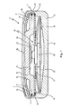
- Fig. 1 is schematic, not to scale and shown in side section a temperature-dependent switch 10 having a housing 11 having an electrically conductive, pot-like base 12 has.
- an inner circumferential shoulder 14 is provided, on the interposition of an insulating film 15, a plate-like, electrically conductive lid member 16 rests, which closes the lower part 12.
- the cover part 16 has a circumferential end face 17, which separates an upper side 18 from an inner side 19.
- the insulating film 15 extends along the inner side 19 and along the end face 17 and extends with its edge region 21 except for the upper side 18.
- the lower part 12 has above the shoulder 14 a cylindrical circumferential wall 22, the upper portion 23 is bent over to the top 18 and the lid member 16 holds with the interposition of the insulating film 15 to the lower part 12.
- the insulating film 15 thus ensures electrical insulation of the cover part 16 relative to the lower part 12. At the same time, the insulating film 15 ensures a mechanical seal between the cover part 16 and lower part 12th
- a temperature-dependent switching mechanism 24 is arranged, which comprises a spring snap-action disc 25 which carries a movable contact member 26 centrally, on which a freely inserted bimetal snap-action disc 27 is seated.
- the spring snap-action disk 25 is supported on a bottom 28 on the inside of the lower part 12, while the movable contact part 26 is in contact with a stationary counter-contact 31 through a central opening 29 in the insulating film 15, which is provided on the inside 19 of the cover part 16 is.
- the external connection are used in the switch 10 Fig. 1 two contact surfaces 32, 33, which are formed on the one hand in a central region of the top 18 and on the other to the bent portion 23 of the wall 22.
- the lower part 12 has a flat underside 34, via which the switch 10 is thermally coupled to a device to be protected.
- the temperature-dependent switching mechanism 24 in the in Fig. 1 shown low-temperature position an electrically conductive connection between the two outer contact surfaces 32, 33 forth, the operating current on the stationary counter-contact 31, the movable contact member 26, the spring snap-action disc 25 and the lower part 12 flows.
- areas of the underside 34 or a circumferential surface 35 of the lower part 12 may also serve.
- Fig. 2 is a modification of the switch 10
- Fig. 1 is shown as a further embodiment of the new switch 10 ', wherein for the switches 10, 10' like reference numerals have been used for identical design features.
- the spring snap-action disk 25 lies here with its edge 36 on the shoulder 14 of the lower part 12 and is held there by a spacer ring 37, on which in turn the insulating film 15 and on this the cover part 16 rests.
- the spring snap-action disk 25 again carries the movable contact part 26, which interacts with the stationary counter contact 31 on the inside 19 of the cover part 16.
- the bimetallic snap disk 27 is arranged on the movable contact part 26, which in the in Fig.2 shown closed state is free of forces.
- an insulating protective film 41 for example made of Nomex ® arranged, which extends with its edge 42 radially outward to the insulating film 15.
- the protective film leaves free a region 43, by means of which the contact surface 32 on the upper side 18 can be electrically contacted from the outside.
- the switch 10 'off Fig. 2 is shown in a stage in which the raised wall 22 of the lower part 12 has not been completely bent over to the top 18, wherein for reasons of clarity, the left and the right portion of the Fig. 2 connecting edges 44 and 45 of raised wall 22 and insulating film 15 are shown broken. Upon further bending of the portion 23 of the wall 22, the insulating film 15 continues down to the top 18th
- the section 23 can press the edge region 21 of the insulating film 15 and possibly the protective film 41 onto the upper side 18 in such a way that such a good electrical insulation and a mechanical seal between the lower part 12 and the cover part 16 is achieved that an applied protective lacquer 46 as he is in Fig. 1 is indicated, can not penetrate between the lower part 12 and the cover part 16 in the housing 11.
- the cover part 16 exerts a radially outwardly directed pressure on the inside of the wall 22 via the insulating film 15, which leads to a particularly good sealing of the switches 10 and 10 '.
- the pressure is in the Fig. 1 and 2 indicated by P.
- Fig. 3 is a schematic and not to scale, sectional side view of a lower part 12 is shown, above the also schematically and not to scale an insulating film 15 and a schematically indicated cover part 16 are shown, which is formed here flat.
- the cover part 16 has a thickness 50 and an outer diameter 51, the insulating film 15 has a thickness indicated at 52.
- the lower part 12 is shown before inserting the rear derailleur 24, insulating film 15 and cover member 16, ie in its delivery state in which the wall 22 is not yet bent, but with its circumferential inner side 22a an approximately cylindrical receiving space 53 spans, in the insulating film 15th and cover part 16 and possibly the spacer ring 37 still needs to be inserted.
- the wall 22 has in this state on its inner side a lower cylindrical portion 54 which adjoins directly to the shoulder 14 and above the shoulder 14 has a lower inner diameter 61 and a height indicated at 55, the strength of the cover part 16 if necessary plus the height of the spacer ring 37.
- the cylindrical portion 54 of the wall 22 is followed by a conical portion 56, the inner diameter 57 is in the direction of an opening 58 continuously to an upper diameter (in Fig. 4 denoted by 65) extended, wherein the opening 58 is surrounded there by an end face 59 of the wall 22.
- the lower inner diameter 61 in the region of the cylindrical portion 54 is constant over the height 55.
- the insulating film 15 and the cover member 16 are inserted through the opening 58 into the space 53, so can be on the shoulder 14 to gradually reducing inner diameter 57 initially unhindered insertion.
- the insulating film 15 is clamped between the end face 17 and the inner side 22a of the wall 22, which provides for the bending of the wall 22 on the top 18 of the cover member 16 for a very good seal of the switch.
- the outer diameter 51 ranges from 8.42 to 8.45 mm
- the thickness 52 is between 0.115 and 0.135 mm
- the lower inner diameter 61 ranges from 8.61 to 8.64 mm, so that the oversize is a minimum of 0.01 up to a maximum of 0.11 mm.
- the inner diameter 57 in the region of the conical portion 63 increases from the lower inner diameter 61, which already out Fig. 3 is known, to the upper inner diameter 65 in the region of the upper cylindrical portion 64th
- This lower part 12 thus has a shorter circumferential insertion bevel than the lower part 12 Fig. 3 otherwise, the relative dimensions and operations are the same as the base 12 Fig. 3 , Lid 16 and insulating film 15 can be inserted and aligned here first in the space 53 before they are pressed along the conical section 63 in the cylindrical portion 54, which can lead to a simplification of the assembly.
Landscapes
- Physics & Mathematics (AREA)
- Thermal Sciences (AREA)
- Thermally Actuated Switches (AREA)
- Push-Button Switches (AREA)
Applications Claiming Priority (1)
| Application Number | Priority Date | Filing Date | Title |
|---|---|---|---|
| DE102014110260.6A DE102014110260A1 (de) | 2014-07-22 | 2014-07-22 | Temperaturabhängiger Schalter mit Isolierfolie |
Publications (1)
| Publication Number | Publication Date |
|---|---|
| EP2978007A1 true EP2978007A1 (fr) | 2016-01-27 |
Family
ID=53610790
Family Applications (1)
| Application Number | Title | Priority Date | Filing Date |
|---|---|---|---|
| EP15176424.8A Withdrawn EP2978007A1 (fr) | 2014-07-22 | 2015-07-13 | Commutateur thermosensible avec film isolant |
Country Status (5)
| Country | Link |
|---|---|
| US (1) | US20160027598A1 (fr) |
| EP (1) | EP2978007A1 (fr) |
| CN (1) | CN105280435A (fr) |
| DE (1) | DE102014110260A1 (fr) |
| HK (1) | HK1214030A1 (fr) |
Cited By (1)
| Publication number | Priority date | Publication date | Assignee | Title |
|---|---|---|---|---|
| CN111952117A (zh) * | 2019-05-14 | 2020-11-17 | 马赛尔·P·霍夫萨埃斯 | 温控开关 |
Families Citing this family (3)
| Publication number | Priority date | Publication date | Assignee | Title |
|---|---|---|---|---|
| DE102015110509B4 (de) * | 2015-06-30 | 2019-03-28 | Thermik Gerätebau GmbH | Temperaturabhängiger Schalter mit lsolierscheibe und elektronische Schaltung mit einemauf einer Leiterplatte montierten, temperaturabhängigen Schalter |
| DE102015114248B4 (de) * | 2015-08-27 | 2019-01-17 | Marcel P. HOFSAESS | Temperaturabhängiger Schalter mit Schneidgrat |
| JPWO2019194227A1 (ja) * | 2018-04-06 | 2021-04-15 | 三洋電機株式会社 | 電池 |
Citations (9)
| Publication number | Priority date | Publication date | Assignee | Title |
|---|---|---|---|---|
| GB1033670A (en) * | 1962-12-21 | 1966-06-22 | Texas Instruments Inc | Thermally responsive electrical switches |
| US4091354A (en) * | 1976-06-03 | 1978-05-23 | Therm-O-Disc Incorporated | Bimetal snap disc thermostat arranged to reduce temperature calibration drift |
| DE4337141A1 (de) * | 1993-10-30 | 1995-05-04 | Hofsaes Geb Zeitz Ulrika | Temperaturabhängiger Schalter |
| DE19517310A1 (de) | 1995-05-03 | 1996-11-14 | Thermik Geraetebau Gmbh | Baustein aus Kaltleitermaterial |
| DE19623570A1 (de) | 1996-06-13 | 1998-01-02 | Marcel Hofsaes | Temperaturwächter mit einer Kaptonfolie |
| DE19754158A1 (de) | 1997-10-28 | 1999-05-12 | Marcel Hofsaes | Verfahren zum Isolieren eines elektrischen Bauteiles |
| DE19827113A1 (de) | 1998-06-18 | 1999-12-30 | Marcel Hofsaes | Temperaturabhängiger Schalter mit Stromübertragungsglied |
| DE102009030353B3 (de) | 2009-06-22 | 2010-12-02 | Hofsaess, Marcel P. | Kappe für einen temperaturabhängigen Schalter sowie Verfahren zur Fertigung eines temperaturabhängigen Schalters |
| DE102009039948A1 (de) | 2009-08-27 | 2011-03-03 | Hofsaess, Marcel P. | Temperaturabhängiger Schalter |
Family Cites Families (1)
| Publication number | Priority date | Publication date | Assignee | Title |
|---|---|---|---|---|
| CN203481139U (zh) * | 2013-09-29 | 2014-03-12 | 扬州宝珠电器有限公司 | 过热过流延时复位保护器 |
-
2014
- 2014-07-22 DE DE102014110260.6A patent/DE102014110260A1/de not_active Withdrawn
-
2015
- 2015-07-13 EP EP15176424.8A patent/EP2978007A1/fr not_active Withdrawn
- 2015-07-20 US US14/803,564 patent/US20160027598A1/en not_active Abandoned
- 2015-07-21 CN CN201510431344.2A patent/CN105280435A/zh active Pending
-
2016
- 2016-02-18 HK HK16101831.3A patent/HK1214030A1/zh unknown
Patent Citations (10)
| Publication number | Priority date | Publication date | Assignee | Title |
|---|---|---|---|---|
| GB1033670A (en) * | 1962-12-21 | 1966-06-22 | Texas Instruments Inc | Thermally responsive electrical switches |
| US4091354A (en) * | 1976-06-03 | 1978-05-23 | Therm-O-Disc Incorporated | Bimetal snap disc thermostat arranged to reduce temperature calibration drift |
| DE4337141A1 (de) * | 1993-10-30 | 1995-05-04 | Hofsaes Geb Zeitz Ulrika | Temperaturabhängiger Schalter |
| DE19517310A1 (de) | 1995-05-03 | 1996-11-14 | Thermik Geraetebau Gmbh | Baustein aus Kaltleitermaterial |
| DE19623570A1 (de) | 1996-06-13 | 1998-01-02 | Marcel Hofsaes | Temperaturwächter mit einer Kaptonfolie |
| DE19754158A1 (de) | 1997-10-28 | 1999-05-12 | Marcel Hofsaes | Verfahren zum Isolieren eines elektrischen Bauteiles |
| DE19827113A1 (de) | 1998-06-18 | 1999-12-30 | Marcel Hofsaes | Temperaturabhängiger Schalter mit Stromübertragungsglied |
| DE19827113C2 (de) | 1998-06-18 | 2001-11-29 | Marcel Hofsaes | Temperaturabhängiger Schalter mit Stromübertragungsglied |
| DE102009030353B3 (de) | 2009-06-22 | 2010-12-02 | Hofsaess, Marcel P. | Kappe für einen temperaturabhängigen Schalter sowie Verfahren zur Fertigung eines temperaturabhängigen Schalters |
| DE102009039948A1 (de) | 2009-08-27 | 2011-03-03 | Hofsaess, Marcel P. | Temperaturabhängiger Schalter |
Cited By (2)
| Publication number | Priority date | Publication date | Assignee | Title |
|---|---|---|---|---|
| CN111952117A (zh) * | 2019-05-14 | 2020-11-17 | 马赛尔·P·霍夫萨埃斯 | 温控开关 |
| CN111952117B (zh) * | 2019-05-14 | 2023-03-28 | 马赛尔·P·霍夫萨埃斯 | 温控开关 |
Also Published As
| Publication number | Publication date |
|---|---|
| DE102014110260A1 (de) | 2016-01-28 |
| US20160027598A1 (en) | 2016-01-28 |
| HK1214030A1 (zh) | 2016-07-15 |
| CN105280435A (zh) | 2016-01-27 |
Similar Documents
| Publication | Publication Date | Title |
|---|---|---|
| EP2775495B1 (fr) | Commutateur thermosensible avec plaque isolante | |
| DE102013102006B4 (de) | Temperaturabhängiger Schalter | |
| DE102008048554B3 (de) | Temperaturabhängiger Schalter | |
| EP3136416B1 (fr) | Commutateur thermodépendant comprenant un dispositif de coupe | |
| EP2874171B1 (fr) | Mécanisme de commutation variable avec la température | |
| DE102015110509B4 (de) | Temperaturabhängiger Schalter mit lsolierscheibe und elektronische Schaltung mit einemauf einer Leiterplatte montierten, temperaturabhängigen Schalter | |
| EP2978007A1 (fr) | Commutateur thermosensible avec film isolant | |
| EP2854149B1 (fr) | Commutateur thermosensible doté d'un disque à action rapide disposé sur le bord | |
| EP2743954B1 (fr) | Commutateur thermodépendant | |
| DE102011119633B3 (de) | Temperaturabhängiger Schalter | |
| DE102011119637B4 (de) | Temperaturabhängiger Schalter mit einem temperaturabhängigen Schaltwerk sowie Verfahren zum Herstellen eines solchen Schalters | |
| EP2654057B1 (fr) | Commutateur thermodépendant | |
| DE102018130078B4 (de) | Temperaturabhängiger Schalter | |
| EP3270401B1 (fr) | Commutateur thermique doté de vitre isolante | |
| EP3024010B1 (fr) | Commutateur thermique | |
| EP3796360B1 (fr) | Commutateur dépendant de la température | |
| DE102019111279B4 (de) | Temperaturabhängiger Schalter | |
| DE102015017281B3 (de) | Temperaturabhängiger Schalter mit Isolierscheibe und elektronische Schaltung | |
| DE102023102303B3 (de) | Temperaturabhängiger Schalter | |
| DE102011122890A1 (de) | Temperaturabhängiges Schaltwerk |
Legal Events
| Date | Code | Title | Description |
|---|---|---|---|
| PUAI | Public reference made under article 153(3) epc to a published international application that has entered the european phase |
Free format text: ORIGINAL CODE: 0009012 |
|
| AK | Designated contracting states |
Kind code of ref document: A1 Designated state(s): AL AT BE BG CH CY CZ DE DK EE ES FI FR GB GR HR HU IE IS IT LI LT LU LV MC MK MT NL NO PL PT RO RS SE SI SK SM TR |
|
| AX | Request for extension of the european patent |
Extension state: BA ME |
|
| STAA | Information on the status of an ep patent application or granted ep patent |
Free format text: STATUS: THE APPLICATION IS DEEMED TO BE WITHDRAWN |
|
| 18D | Application deemed to be withdrawn |
Effective date: 20160728 |