EP2977678A1 - Élément de garniture pour une chambre de combustion - Google Patents
Élément de garniture pour une chambre de combustion Download PDFInfo
- Publication number
- EP2977678A1 EP2977678A1 EP15174882.9A EP15174882A EP2977678A1 EP 2977678 A1 EP2977678 A1 EP 2977678A1 EP 15174882 A EP15174882 A EP 15174882A EP 2977678 A1 EP2977678 A1 EP 2977678A1
- Authority
- EP
- European Patent Office
- Prior art keywords
- liner element
- cooling side
- combustor
- liner
- protuberances
- Prior art date
- Legal status (The legal status is an assumption and is not a legal conclusion. Google has not performed a legal analysis and makes no representation as to the accuracy of the status listed.)
- Granted
Links
- 238000001816 cooling Methods 0.000 claims abstract description 92
- 238000002485 combustion reaction Methods 0.000 claims abstract description 47
- 238000010276 construction Methods 0.000 claims abstract description 9
- 230000002093 peripheral effect Effects 0.000 claims description 14
- 238000000034 method Methods 0.000 description 25
- 238000004140 cleaning Methods 0.000 description 18
- 239000012720 thermal barrier coating Substances 0.000 description 15
- 239000007789 gas Substances 0.000 description 10
- 239000011248 coating agent Substances 0.000 description 9
- 238000000576 coating method Methods 0.000 description 9
- 238000004519 manufacturing process Methods 0.000 description 9
- 239000000446 fuel Substances 0.000 description 6
- 239000000654 additive Substances 0.000 description 5
- 230000000996 additive effect Effects 0.000 description 5
- 239000000463 material Substances 0.000 description 5
- 239000002184 metal Substances 0.000 description 5
- 229910052751 metal Inorganic materials 0.000 description 5
- PXHVJJICTQNCMI-UHFFFAOYSA-N Nickel Chemical compound [Ni] PXHVJJICTQNCMI-UHFFFAOYSA-N 0.000 description 4
- 229910045601 alloy Inorganic materials 0.000 description 4
- 239000000956 alloy Substances 0.000 description 4
- 239000000203 mixture Substances 0.000 description 4
- 229910000601 superalloy Inorganic materials 0.000 description 4
- XLYOFNOQVPJJNP-UHFFFAOYSA-N water Substances O XLYOFNOQVPJJNP-UHFFFAOYSA-N 0.000 description 4
- 230000008021 deposition Effects 0.000 description 3
- 239000010408 film Substances 0.000 description 3
- 230000001141 propulsive effect Effects 0.000 description 3
- XEEYBQQBJWHFJM-UHFFFAOYSA-N Iron Chemical compound [Fe] XEEYBQQBJWHFJM-UHFFFAOYSA-N 0.000 description 2
- MCMNRKCIXSYSNV-UHFFFAOYSA-N Zirconium dioxide Chemical compound O=[Zr]=O MCMNRKCIXSYSNV-UHFFFAOYSA-N 0.000 description 2
- 230000008901 benefit Effects 0.000 description 2
- 230000015572 biosynthetic process Effects 0.000 description 2
- 230000000903 blocking effect Effects 0.000 description 2
- 238000005266 casting Methods 0.000 description 2
- 238000005520 cutting process Methods 0.000 description 2
- 230000032798 delamination Effects 0.000 description 2
- 239000012530 fluid Substances 0.000 description 2
- 238000003698 laser cutting Methods 0.000 description 2
- 238000012986 modification Methods 0.000 description 2
- 230000004048 modification Effects 0.000 description 2
- 229910052759 nickel Inorganic materials 0.000 description 2
- 238000007789 sealing Methods 0.000 description 2
- 239000007921 spray Substances 0.000 description 2
- 239000010409 thin film Substances 0.000 description 2
- 230000002411 adverse Effects 0.000 description 1
- 230000004888 barrier function Effects 0.000 description 1
- 239000000919 ceramic Substances 0.000 description 1
- 229910017052 cobalt Inorganic materials 0.000 description 1
- 239000010941 cobalt Substances 0.000 description 1
- GUTLYIVDDKVIGB-UHFFFAOYSA-N cobalt atom Chemical compound [Co] GUTLYIVDDKVIGB-UHFFFAOYSA-N 0.000 description 1
- 230000006835 compression Effects 0.000 description 1
- 238000007906 compression Methods 0.000 description 1
- 238000005336 cracking Methods 0.000 description 1
- 230000006378 damage Effects 0.000 description 1
- 230000002939 deleterious effect Effects 0.000 description 1
- 238000005137 deposition process Methods 0.000 description 1
- 238000005553 drilling Methods 0.000 description 1
- 230000000694 effects Effects 0.000 description 1
- 229910052742 iron Inorganic materials 0.000 description 1
- 150000002739 metals Chemical class 0.000 description 1
- 239000002245 particle Substances 0.000 description 1
- 238000007750 plasma spraying Methods 0.000 description 1
- 230000002028 premature Effects 0.000 description 1
- 125000006850 spacer group Chemical group 0.000 description 1
- 230000003685 thermal hair damage Effects 0.000 description 1
- 238000011144 upstream manufacturing Methods 0.000 description 1
- RUDFQVOCFDJEEF-UHFFFAOYSA-N yttrium(III) oxide Inorganic materials [O-2].[O-2].[O-2].[Y+3].[Y+3] RUDFQVOCFDJEEF-UHFFFAOYSA-N 0.000 description 1
Images


Classifications
-
- F—MECHANICAL ENGINEERING; LIGHTING; HEATING; WEAPONS; BLASTING
- F23—COMBUSTION APPARATUS; COMBUSTION PROCESSES
- F23R—GENERATING COMBUSTION PRODUCTS OF HIGH PRESSURE OR HIGH VELOCITY, e.g. GAS-TURBINE COMBUSTION CHAMBERS
- F23R3/00—Continuous combustion chambers using liquid or gaseous fuel
- F23R3/02—Continuous combustion chambers using liquid or gaseous fuel characterised by the air-flow or gas-flow configuration
- F23R3/04—Air inlet arrangements
- F23R3/10—Air inlet arrangements for primary air
-
- F—MECHANICAL ENGINEERING; LIGHTING; HEATING; WEAPONS; BLASTING
- F23—COMBUSTION APPARATUS; COMBUSTION PROCESSES
- F23R—GENERATING COMBUSTION PRODUCTS OF HIGH PRESSURE OR HIGH VELOCITY, e.g. GAS-TURBINE COMBUSTION CHAMBERS
- F23R3/00—Continuous combustion chambers using liquid or gaseous fuel
- F23R3/002—Wall structures
-
- F—MECHANICAL ENGINEERING; LIGHTING; HEATING; WEAPONS; BLASTING
- F23—COMBUSTION APPARATUS; COMBUSTION PROCESSES
- F23R—GENERATING COMBUSTION PRODUCTS OF HIGH PRESSURE OR HIGH VELOCITY, e.g. GAS-TURBINE COMBUSTION CHAMBERS
- F23R3/00—Continuous combustion chambers using liquid or gaseous fuel
- F23R3/42—Continuous combustion chambers using liquid or gaseous fuel characterised by the arrangement or form of the flame tubes or combustion chambers
- F23R3/60—Support structures; Attaching or mounting means
-
- F—MECHANICAL ENGINEERING; LIGHTING; HEATING; WEAPONS; BLASTING
- F23—COMBUSTION APPARATUS; COMBUSTION PROCESSES
- F23R—GENERATING COMBUSTION PRODUCTS OF HIGH PRESSURE OR HIGH VELOCITY, e.g. GAS-TURBINE COMBUSTION CHAMBERS
- F23R2900/00—Special features of, or arrangements for continuous combustion chambers; Combustion processes therefor
- F23R2900/03041—Effusion cooled combustion chamber walls or domes
Definitions
- the present invention relates to a liner element for a gas turbine combustor.
- One way of cooling the combustor wall with compressor air in this manner involves the provision of a double wall combustor construction having a continuous outer wall and an inner wall made up of a number of separate and replaceable wall elements in the form of tiles which are affixed to the outer wall in a tessellated manner.
- the inner wall tiles are each configured to be affixed to the outer wall of the combustor so as to define a chamber between a cooling side surface of the tile and the outer wall.
- the outer wall is provided with a number of feed holes through which cooling air drawn from the engine's compressor is directed so as to pass into the chambers defined between each inner tile and the outer wall, for impingement on the aforementioned cooling side surface of the inner tile, thereby providing impingement cooling to the inner tile.
- the inner tiles are each furthermore provided with a plurality of so-called effusion holes which define flow passages through the tiles from their cooling side surfaces to oppositely directed combustion side surfaces which face the interior of the combustor where combustion will take place during operation of the engine.
- the cooling air which is directed into the chambers and which impinges on the cooling side surface of the tiles is thus exhausted through the effusion holes and in doing so provides convective heat removal from the tiles.
- the air subsequently forms a thin film of air over the tiles' combustion side surfaces which helps to protect the tiles from the combustion flame inside the combustor.
- the effusion holes are often inclined relative to the combustion side surface.
- Combustor wall arrangements of the type described above thus provide both impingement and effusion cooling of the combustor wall construction, and the tiles are sometimes referred to as impingement/effusion ("IE") tiles.
- IE impingement/effusion
- US 5,435,139 describes a tile system of the general type described above. This document also shows how the tiles are typically affixed to the outer wall of the combustor. Each tile has a number of integrally-formed threaded studs which protrude outwardly from the cold side of the tile and which are received through respective apertures formed in the outer wall of the combustor and engaged by respective self-locking nuts on the outer side of the outer wall.
- Tiles of the type described above are typically formed from a nickel based alloy, and have their combustion side surfaces protected by a thermal barrier coating to insulate the tile and thereby maintain the temperature of the metal within acceptable levels.
- the thermal barrier coating is usually applied in two parts: an initial bond coat (such as a CoNiCrAly composition); and a thermally insulating top coat which may comprise Yttria Partially Stabilised Zirconia ("PYSZ") and which is applied over the bond coat.
- the bond coat is applied directly to the metal of the tiles, for example by air plasma spray, to ensure adherence of the subsequent top coat.
- the bond coat may typically have a thickness of between 0.05mm and 0.2mm, whilst the top coat usually has a thickness of between 0.1 mm and 0.5mm.
- One such process known as a so-called "coat-drill” process involves applying the thermal barrier coat to the combustion side surface of a tile, and then subsequently forming the effusion holes through both the alloy of the tile and the coating. This usually involves forming the holes either by mechanical drilling or by laser from the combustion side, firstly through the thermal barrier coating and then through the metal of the tile.
- This process is relatively simple, in the case of laser-cutting the effusion holes the laser must be operated at reduced power to avoid excessive damage to the brittle ceramic thermal barrier coating. Reducing the power of the cutting laser increases the cycle time necessary to form the holes which can significantly increase the production cost of the tiles.
- forming the effusion holes through the thermal barrier coating can cause cracking and delamination in the coating which can lead to premature loss of the coating during service, resulting in potential thermal damage to the tiles.
- FIG. 1 shows an IE tile 1 having a cooling side 2 and a combustion side 3.
- the cooling side 2 of the tile defines a cooling side surface 4
- the combustion side 3 of the tile defines a combustion side surface 5 which in use will be directed to the region of a combustor in which combustion will take place.
- the effusion holes 6 can be seen to extend between the cooling side surface 4 and the combustion side surface 5 at an inclined angle to the combustion side surface 5.
- Figure 1 also illustrates a pair of externally threaded attachment studs 7 of the type described above in the prior art, which protrude from the cooling side 2 of the tile for receipt through respective apertures formed in the outer wall of a combustor (not shown).
- the attachment studs must have sufficient length to extend across the cavity which will be formed between the cooling side surface 4 of the tile and the outer wall of the combustor, and then project through the apertures in the outer wall by a sufficient degree to engage a threaded nut.
- a typical IE tile may have up to eight attachment studs 7 of this type, provided in spaced-apart relation to one another over the cooling side of the tile.
- Figure 1 also shows a cleaning nozzle 8 which is used to direct a jet of cleaning water or air towards the effusion holes 6 as illustrated, in order to clean the effusion holes of any coating material that may collect therein during the step of applying a thermal barrier coating to the combustion side surface 5 as described above.
- the nozzle 8 is positioned to direct a jet along a jet axis 9 towards each effusion hole 6, the jet axis 9 being inclined relative to the combustion side surface 5 by the same angle as the effusion holes so that the jet is directed through the holes.
- the nozzle 8 may be moved across the cooling side of the tile 1, for example in a scanning manner, to direct its cleaning jet though successive effusion holes.
- the nozzle 8 should be spaced from the cooling side surface 4 by a distance of approximately 30mm or less, as measured along the jet axis 9.
- the length of the attachment studs 7 precludes this because clashes occur between the nozzle 8 and the studs 7 as the nozzle is moved across the cooling side 2 of the tile at a range of anything less than 50mm measured along the jet axis 9.
- the length of the studs 7 can also preclude the jet being properly directed towards several effusion holes proximate to each stud, those holes thus effectively sitting in the "shadow" of the studs.
- DLD Direct Laser Deposition
- a liner element for a gas turbine combustor having a structural wall, the liner element having a unitary construction defining a cooling side and a combustion side, and a plurality of effusion holes extending between a cooling side surface of the liner element and a combustion side surface of the liner element; the liner element being configured to be affixed to the structural wall of a combustor with its cooling side surface spaced from the structural wall to define a chamber between the cooling side surface and the structural wall, wherein the liner element further includes integrally formed and internally threaded protuberances on its cooling side, the protuberances being spaced from the cooling side surface, the protuberances being arranged to engage the structural wall.
- each protuberance is provided in the form of a boss projecting from the cooling side of the liner element.
- the liner element has a peripheral flange configured to engage said structural wall of the combustor when the liner element is affixed thereto, wherein at least some of said protuberances project from said flange.
- Said protuberances projecting from the flange may protrude by a distance of between 2mm and 8mm and may, for example protrude by a distance of approximately 5mm.
- the peripheral flange may support at least one tab, each tab extending inwardly from the periphery of the liner element towards the centre of the liner element, each tab being spaced from the cooling side surface and each tab supporting a protuberance which extends away from the cooling side surface of the liner element.
- the liner element may have at least one centrally located web projecting from said cooling side surface, the or each said web supporting a said protuberance.
- said effusion holes define respective flow channels through the liner element having respective axes which are inclined relative to said combustion side surface.
- some of said effusion holes are proximate to said protuberances and are larger than other effusion holes which are distal to said protuberances.
- Some of said effusion holes may be provided underneath at least one of the protuberances.
- the effusion holes may have respective axes which are arranged perpendicularly to said combustion side surface.
- the liner element may be provided in combination with a said gas turbine combustor, wherein the liner element is affixed to the structural wall of the combustor by a plurality of threaded bolts, each bolt extending through a respective fixing aperture formed in the structural wall and threadedly engaging a respective protuberance.
- each protuberance is engaged within a respective said fixing aperture.
- each protuberance projects through a respective said fixing aperture.
- At least one of the threaded bolts may have a centrally located passage, the centrally located passage extends the full length of the threaded bolt and the corresponding protuberance has a bore which extends completely though the protuberance.
- a gas turbine combustor having a structural wall and a liner element, the liner element having a unitary construction defining a cooling side and a combustion side, a plurality of effusion holes extending between a cooling side surface of the liner element and a combustion side surface of the liner element; the liner element being affixed to the structural wall of the combustor with its cooling side surface spaced from the structural wall to define a chamber between the cooling side surface and the structural wall, wherein the liner element includes a peripheral flange configured to engage said structural wall of the combustor when the liner element is affixed thereto, the liner element further includes integrally formed and internally threaded protuberances on its cooling side, the protuberances being spaced from the cooling side surface, the protuberances being arranged to engage the structural wall, wherein at least some of said protuberances project from said flange, the liner element is affixed to the structural wall of
- Some of said effusion holes may be provided underneath at least one of the protuberances, the at least one protuberance has a bore which extends completely though the protuberance, the corresponding threaded bolt has a centrally located passage and the centrally located passage extends the full length of the threaded bolt.
- a gas turbine combustor having a structural wall and a liner element, the liner element having a unitary construction defining a cooling side and a combustion side, a plurality of effusion holes extending between a cooling side surface of the liner element and a combustion side surface of the liner element; the liner element being affixed to the structural wall of the combustor with its cooling side surface spaced from the structural wall to define a chamber between the cooling side surface and the structural wall, wherein the liner element includes a peripheral flange configured to engage said structural wall of the combustor when the liner element is affixed thereto, the liner element further includes integrally formed and internally threaded protuberances on its cooling side, the protuberances being spaced from the cooling side surface, the protuberances being arranged to engage the structural wall, at least one centrally located web projecting from said cooling side surface, the or each said web supporting a said protuberance, the liner element
- Some of said effusion holes may be provided underneath at least one of the protuberances, the at least one protuberance has a bore which extends completely though the protuberance, the corresponding threaded bolt has a centrally located passage and the centrally located passage extends the full length of the threaded bolt.
- the at least one centrally located web may be configured to engage said structural wall of the combustor when the liner element is affixed thereto.
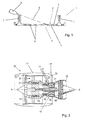
- Figure 2 shows a ducted fan gas turbine engine 10 which incorporates the invention and has a principal and rotational axis X-X.
- the engine comprises, in axial flow series, an air intake 11, a propulsive fan 12, an intermediate pressure compressor 13, a high-pressure compressor 14, combustion equipment 15, a high-pressure turbine 16, an intermediate pressure turbine 17, a low-pressure turbine 18 and a core engine exhaust nozzle 19.
- a nacelle 21 generally surrounds the engine 10 and defines the intake 11, a bypass duct 22 and a bypass exhaust nozzle 23.
- air entering the intake 11 is accelerated by the fan 12 to produce two air flows: a first air flow A into the intermediate pressure compressor 13 and a second air flow B which passes through the bypass duct 22 to provide propulsive thrust.
- the intermediate pressure compressor 13 compresses the air flow A directed into it before delivering that air to the high pressure compressor 14 where further compression takes place.
- the compressed air exhausted from the high-pressure compressor 14 is directed into the combustion equipment 15 where it is mixed with fuel and the mixture combusted.
- the resultant hot combustion products then expand through, and thereby drive the high, intermediate and low-pressure turbines 16, 17, 18 before being exhausted through the nozzle 19 to provide additional propulsive thrust.
- the high, intermediate and low-pressure turbines respectively drive the high and intermediate pressure compressors 14, 13 and the fan 12 by suitable interconnecting shafts.
- the combustion equipment 15 comprises an annular combustor 24 having radially inner and outer walls 25, 26 respectively. Fuel is directed into the combustor 24 through a number of fuel nozzles located at the upstream end 27 of the combustor. The fuel nozzles are circumferentially spaced around the engine 10 and serve to spray fuel into air derived from the high pressure compressor 14. The resultant fuel/air mixture is then combusted within the combustor 24.
- a region of the radially outer wall structure 26 is shown in more detail in Figure 3 . It is to be appreciated, however, that the radially inner wall structure 25 is of the same general configuration as the radially outer wall structure 26.
- the radially outer wall structure 26 comprises an outer structural wall 28 and an inner wall 29.
- the inner wall 29 is formed from a plurality of liner elements 30, one of which is illustrated in figure 4 , which are affixed to the outer wall 28 so as to lie adjacent one another in a tessellated manner.
- the liner elements 30 making up the inner wall thus each define a respective tile and collectively define a liner to the outer structural wall 28 of the combustor 24.
- each liner element 30 is spaced from the outer wall 28 to define a chamber 31 between the outer wall 28 and each liner element 30 in the manner of a conventional IE tile of the type described in the introduction above.
- the air is then exhausted from the chambers 31 though a plurality of angled effusion holes 35 provided through each liner element 30.
- the effusion holes 35 thus define respective flow channels through the liner element 30 having respective axes which are inclined relative to the radially outward surface 34.
- the effusion holes 35 are so angled as to be aligned in a generally downstream direction with regard to the general fluid flow direction through the combustor.
- the air exhausted from the effusion holes 35 forms a film of cooling air over the radially inward surface 36 of each liner element 30, which is the surface confronting the combustion process which takes place within the combustor 24. This film of cooling air assists in protecting the liner elements 30 from the effects of the high temperature gases within the combustor 24.
- each liner element 30 effectively has a radially outward cooling side, indicated generally at 37 in Figure 3 , and a radially inward combustion side, indicated generally at 38 in Figure 3 .
- the radially outward surface 34 of each liner element, on its cooling side can thus be considered to represent a cooling side surface.
- the radially inward surface 36 of each liner element, on its combustion side can thus be considered to represent a combustion side surface.
- FIG. 4 there is shown a complete liner element 30 in the form of an IE tile.
- the liner element 30 is illustrated as viewed from its cooling side 37, with its oppositely directed combustion side 38 facing downwardly in the orientation shown.
- the major extent of the liner element, in which the effusion holes 35 are provided, is shown cross-hatched in Figure 4 , the individual effusion holes not actually being shown.
- the cooling side surface 34 is shown facing upwardly, and the combustion side surface 36 faces downwardly and so is not visible in Figure 4 .
- the liner element 30 is formed from a suitable metal such as a superalloy. Suitable metals for the liner element 30 include nickel-based superalloy, cobalt-based superalloy and iron-based superalloy.
- the liner element 30 is preferably formed as a unitary construction via either a casting process or an additive layer manufacturing technique such as direct laser deposition. In the case of the liner element 30 being cast, then it envisaged that the effusion holes 35 will be formed after the casting process, for example by a laser cutting technique.
- the effusion holes 35 can be formed simultaneously with the rest of the liner element as it is built up.
- the liner element 30 has an integrally formed peripheral flange 39, which extends radially in the orientation illustrated in Figure 4 , away from the cooling side 37 of the liner element 30.
- the flange 39 is configured to engage the outer wall 28 of the combustor 24 when the liner element 30 is affixed to the outer wall, and thereby serves to define the perimeter of the chamber 31 defined between the outer wall 28 and the liner element 30 and to space the cooling side surface 34 from the outer wall 28 in the manner illustrated in Figure 3 .
- each tab 40 supports a respective integrally formed protuberance 41 which extends radially away from the cooling side surface 34 of the liner element and thus projects from the cooling side 37 of the liner element.
- Each protuberance is provided in the form of a short boss, having a central and internally threaded bore 42.
- the threaded bore 42 of each boss 41 may extend completely through the boss and its respective supporting tab 40 as illustrated in cross-section in Figure 5 which shows a pair of such bosses 41 carried by respective adjacent liner elements 30.
- the bores 42 can be blind in the sense that they are open at the free ends of the respective bosses but closed at their tab ends.
- each boss 41 is generally cylindrical in form. Also shown in Figure 4 is a centrally located boss 41 of generally identical form which extends rearwardly from a central region of the cooling side 37 of the liner element.
- This non-peripheral and centrally located boss 41 is illustrated in more detail in Figures 6 and 7 , in which it can be seen that the boss 41 is supported by a web 43 which projects from the cooling side surface 34. It is to be appreciated that whilst the particular liner element 30 illustrated in Figure 4 has only one non-peripheral boss 41 of this type, it is possible for a liner element 30 to have more than one such boss.
- FIGS 5, 6 and 7 show the liner element(s) 30 in combination with the outer wall 28 of the combustor, and more particularly illustrate the function of the bosses 41 in attaching the liner elements to the outer wall 28.
- each boss 41 is arranged and configured to engage the outer wall 28, and more particularly to be received and engaged within and to extend through a respective fixing aperture 44 provided through the outer wall 28.
- the liner element 30 is offered up to the radially inward side of the outer wall 28, with its bosses 41 aligned with respective fixing apertures 44.
- the bosses 41 are then inserted through the fixing apertures and the liner element 30 is pressed towards the outer wall 28 until its peripheral flange (not shown in Figures 6 and 7 ) engages the radially inward surface of the outer wall 28.
- the tabs 40 from which the bosses 41 project, also engage the radially inward surface of the outer wall 28.
- each web 43 from which a centrally located boss 41 projects, also engages the radially inward surface of the outer wall 28.
- bosses 41 each extend through the fixing apertures 44 and protrude from the opposite side.
- a sealing washer 45 may then be fitted over each boss 41, from the radially outward side of the combustor wall 28, followed by a cupped spacer washer 46.
- the cupped spaced washers 46 each bear against a respective sealing washer 45 and extend inwardly over the end of a respective boss 41.
- a respective externally threaded bolt 47 may then be threadedly engaged within the threaded bore 42 of each boss 41 and drawn up tight to securely fix the liner element 30 to the combustor's outer wall 28.
- At least some of the threaded bolts 47 which are used to engage respective bosses 41 in order to fix the liner element 30 to the outer wall 28 of the combustor may each have a centrally located airflow passage 48.
- the airflow passages 48 of the two bolts 47 shown in Figure 5 extend the full length of the bolts 47 and are thus open at the radially outermost ends of the bolts 47 and also at the radially innermost ends of the bolts 47.
- These airflow passages 48 may serve a similar function to the feed holes 32 in the outer wall 28 of the combustor by permitting a flow of cooling air drawn from the engine's high pressure compressor 14 through the bolts 47 for impingement on the cooling side surface 34 of the liner element 30 in the region of the bosses 41. Additionally, the flow of cooling air through the airflow passages 48 in the bolts 47 will also serve to cool the bolts 47 themselves, and to a degree also the bosses 41.
- bolts 47 of this configuration will be used most conveniently to engage the peripheral bosses 41 which protrude from the flange tabs 40, and so it is proposed that the flange tabs 40 will have respective openings 49 to permit exit of the cooling air from the airflow passages 48 in the bolts 47.
- the flow of cooling air through the bolts 47 may also serve to cool the flanges 40.
- bosses 41 are each internally threaded and configured to receive a respective bolt 47, rather than externally threaded for engagement by a nut, they can be configured to be significantly shorter than the externally threaded studs 7 used in the prior art IE tiles. This is because the bosses 41 do not need to project through the fixing apertures 44 as far as the externally threaded studs of the prior art. Indeed, whilst the embodiment illustrated is configured such that the bosses 41 extend through the fixing apertures, it is envisaged that in some embodiments they could instead bear against the surface of the combustor outer wall 28 around respective fixing apertures which would permit the bosses 41 to be even shorter than those illustrated.
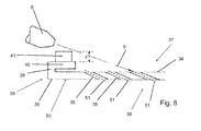
- the lower profile of the bosses 41 in comparison to the externally threaded studs of the prior art, is shown most clearly in figure 8 . It is envisaged that the peripheral bosses 41 around the flange 39 may be configured such that they protrude from the flange by a distance x of only 2 to 8mm, and optionally approximately 5mm.
- the shorter configuration of the bosses 41 offers a significant advantage when applying a thermal barrier coating to the combustion side surface 36 of the liner element 30 by the so-called "drill-coat-clean" method described above, as will now be explained below.
- Figure 8 depicts the liner element 30 after it has had a thermal barrier coating 50 applied to its combustion side surface 36, which may be achieved by any convenient known process such as air plasma spraying.
- a thermal barrier coating 50 applied to its combustion side surface 36, which may be achieved by any convenient known process such as air plasma spraying.
- This is achieved by a cleaning step which uses a similar jetting process to that described above in connection with the prior art, and Figure 8 thus illustrates a jet nozzle 8 positioned on the cooling side 37 of the liner element 30 and which is oriented to direct a jet of cleaning water or air along a jet axis 9 towards and through the effusion holes 35 from the cooling side 37 of the liner element.
- the nozzle 8 is oriented so that the jet axis 9 is substantially parallel to the axes 50 of the flow channels defined by the effusion holes 35.
- the nozzle 8 will be moved across the cooling side 37 of the liner element 30 in spaced relation to the cooling side surface 34, in order to direct the jet through all, or as many as possible, of the effusion holes 35.
- the nozzle 8 can be moved across the cooling side 37 of the liner element in this manner at a much closer spacing from the cooling side surface 34 than in the case of the prior art, without being obstructed by the fixing bosses 41.
- the bosses 41 configured as described above, the nozzle can be maintained at a distance of less than or equal to 30mm from the cooling side surface 34 as measured along the jet axis 9 throughout the cleaning procedure and without fouling or clashing with the bosses 41. The closer range of the cleaning nozzle 8 thus permits significantly improved cleaning of the effusion holes 35.
- the shorter configuration of the fixing bosses 41 also means that there will be fewer effusion holes 35 proximate the bosses 41 which fall into the "shadow" of the bosses 41 (such as the leftmost effusion holes shown in Figure 8 ) and which cannot be targeted so effectively by the cleaning jet. Nevertheless there may still remain some effusion holes 35 proximate the bosses 41 which may not be conveniently targeted by the cleaning jet in the orientation illustrated, and so it is proposed that some of these effusion holes could be made larger than other more easily targeted holes distal to the bosses 41, thereby permitting more variation in the jetting angle used to clean the holes in these regions, and also reducing the likelihood of the thermal barrier coating material completely blocking them.
- the effusion holes 35 will be formed simultaneously with the rest of the liner element.
- the effusion holes will need to be drilled before the thermal barrier coating is applied.
- the shorter length of the fixing bosses 41 also permits more efficient production of the liner elements 30 because they permit a larger number of liner elements 30 to be formed simultaneously in a vertically stacked array, thereby obviating another problem associated with the prior art.
- each boss 41 projecting from a supporting tab 40 on the peripheral flange 39, and each centrally located boss 41 projecting from a supporting web 43 is spaced from the cooling side surface 34 of the liner element 30. It is thus possible to provide effusion holes 35 through the liner element 30 at positions underneath (and thus radially inwardly of) the tabs 40 and their respective bolts 47 and/or at the sides of the webs 43 and underneath (and thus radially inwardly of) their respective bolts 47.
- Figure 8 which shows the angled effusion holes 35 being arranged to direct a flow of air from the cooling side 37 to the combustion side 38 of the liner element and in a generally downstream direction with regard to the general fluid flow direction though a combustor
- the liner element 30 could have conventional fixing studs 7 provided at its downstream end without adversely affecting the cleaning process as described above. It is therefore possible for the liner element 30 to have conventional fixing studs 7 along its downstream edge, but internally threaded bosses 41 of the type described herein elsewhere.
- a liner element 30 of this configuration would be cast.
Landscapes
- Engineering & Computer Science (AREA)
- Chemical & Material Sciences (AREA)
- Combustion & Propulsion (AREA)
- Mechanical Engineering (AREA)
- General Engineering & Computer Science (AREA)
- Turbine Rotor Nozzle Sealing (AREA)
Applications Claiming Priority (1)
| Application Number | Priority Date | Filing Date | Title |
|---|---|---|---|
| GBGB1413194.0A GB201413194D0 (en) | 2014-07-25 | 2014-07-25 | A liner element for a combustor, and a related method |
Publications (2)
| Publication Number | Publication Date |
|---|---|
| EP2977678A1 true EP2977678A1 (fr) | 2016-01-27 |
| EP2977678B1 EP2977678B1 (fr) | 2017-09-20 |
Family
ID=51587228
Family Applications (1)
| Application Number | Title | Priority Date | Filing Date |
|---|---|---|---|
| EP15174882.9A Active EP2977678B1 (fr) | 2014-07-25 | 2015-07-01 | Chambre de combustion pour turbine à gaz avec revêtement |
Country Status (3)
| Country | Link |
|---|---|
| US (1) | US9970660B2 (fr) |
| EP (1) | EP2977678B1 (fr) |
| GB (1) | GB201413194D0 (fr) |
Families Citing this family (5)
| Publication number | Priority date | Publication date | Assignee | Title |
|---|---|---|---|---|
| WO2015009384A1 (fr) * | 2013-07-16 | 2015-01-22 | United Technologies Corporation | Turbine à gaz pourvue d'un panneau en céramique |
| EP3018415B1 (fr) * | 2014-11-07 | 2020-01-01 | United Technologies Corporation | Refroidissement de trou de dilution de chambre de combustion |
| US9945257B2 (en) * | 2015-09-18 | 2018-04-17 | General Electric Company | Ceramic matrix composite ring shroud retention methods-CMC pin-head |
| GB201518345D0 (en) * | 2015-10-16 | 2015-12-02 | Rolls Royce | Combustor for a gas turbine engine |
| US11047575B2 (en) * | 2019-04-15 | 2021-06-29 | Raytheon Technologies Corporation | Combustor heat shield panel |
Citations (5)
| Publication number | Priority date | Publication date | Assignee | Title |
|---|---|---|---|---|
| GB647302A (en) * | 1948-05-14 | 1950-12-13 | Edgar Phillips Peregrine | Improvements in or relating to linings for combustion chambers and the like |
| EP1467151A1 (fr) * | 2003-04-10 | 2004-10-13 | Siemens Aktiengesellschaft | Bouclier thermique |
| EP1635118A2 (fr) * | 2004-09-10 | 2006-03-15 | DLR Deutsches Zentrum für Luft- und Raumfahrt e.V. | Chambre à gaz chauds et bardeau pour une chambre à gaz chauds |
| US20100263386A1 (en) * | 2009-04-16 | 2010-10-21 | General Electric Company | Turbine engine having a liner |
| US20110030378A1 (en) * | 2009-08-05 | 2011-02-10 | Rolls-Royce Plc | Combustor tile mounting arrangement |
Family Cites Families (7)
| Publication number | Priority date | Publication date | Assignee | Title |
|---|---|---|---|---|
| GB1552132A (en) | 1975-11-29 | 1979-09-12 | Rolls Royce | Combustion chambers for gas turbine engines |
| US5435139A (en) | 1991-03-22 | 1995-07-25 | Rolls-Royce Plc | Removable combustor liner for gas turbine engine combustor |
| US5265411A (en) | 1992-10-05 | 1993-11-30 | United Technologies Corporation | Attachment clip |
| EP1741981A1 (fr) | 2005-07-04 | 2007-01-10 | Siemens Aktiengesellschaft | Bouclier thermique en céramique et réacteur à gaz hautes températures recouvert d'un tel bouclier |
| GB2432902B (en) | 2005-12-03 | 2011-01-12 | Alstom Technology Ltd | Gas turbine sub-assemblies |
| GB0610578D0 (en) | 2006-05-27 | 2006-07-05 | Rolls Royce Plc | Method of removing deposits |
| DE102007018061A1 (de) * | 2007-04-17 | 2008-10-23 | Rolls-Royce Deutschland Ltd & Co Kg | Gasturbinenbrennkammerwand |
-
2014
- 2014-07-25 GB GBGB1413194.0A patent/GB201413194D0/en not_active Ceased
-
2015
- 2015-07-01 US US14/789,322 patent/US9970660B2/en active Active
- 2015-07-01 EP EP15174882.9A patent/EP2977678B1/fr active Active
Patent Citations (5)
| Publication number | Priority date | Publication date | Assignee | Title |
|---|---|---|---|---|
| GB647302A (en) * | 1948-05-14 | 1950-12-13 | Edgar Phillips Peregrine | Improvements in or relating to linings for combustion chambers and the like |
| EP1467151A1 (fr) * | 2003-04-10 | 2004-10-13 | Siemens Aktiengesellschaft | Bouclier thermique |
| EP1635118A2 (fr) * | 2004-09-10 | 2006-03-15 | DLR Deutsches Zentrum für Luft- und Raumfahrt e.V. | Chambre à gaz chauds et bardeau pour une chambre à gaz chauds |
| US20100263386A1 (en) * | 2009-04-16 | 2010-10-21 | General Electric Company | Turbine engine having a liner |
| US20110030378A1 (en) * | 2009-08-05 | 2011-02-10 | Rolls-Royce Plc | Combustor tile mounting arrangement |
Also Published As
| Publication number | Publication date |
|---|---|
| EP2977678B1 (fr) | 2017-09-20 |
| US9970660B2 (en) | 2018-05-15 |
| GB201413194D0 (en) | 2014-09-10 |
| US20160025345A1 (en) | 2016-01-28 |
Similar Documents
| Publication | Publication Date | Title |
|---|---|---|
| EP3009744B1 (fr) | Élément de garniture pour une chambre de combustion et procédé associé | |
| US8661826B2 (en) | Combustion apparatus | |
| EP2977678B1 (fr) | Chambre de combustion pour turbine à gaz avec revêtement | |
| EP3015648B1 (fr) | Composant refroidi | |
| US10502421B2 (en) | Combustion chamber and a combustion chamber segment | |
| EP1632720B1 (fr) | Réglage du débit d'air dans un élément de turbine par dépôt d'une couche superficielle métallique | |
| EP2846097B1 (fr) | Chambre de combustion d'une turbine à gaz avec des plaques& xA;ayant des orifices de refroidissement par pellicule | |
| EP2562479B1 (fr) | Éléments muraux pour moteurs à turbine à gaz | |
| JP5639852B2 (ja) | 熱シールド装置及び、その交換方法 | |
| US20040083739A1 (en) | Combustion apparatus | |
| US20090142548A1 (en) | Air cooled gas turbine components and methods of manufacturing and repairing the same | |
| US20140141174A1 (en) | Method of manufacturing a thermal barrier coated article | |
| US10907830B2 (en) | Combustor chamber arrangement with sealing ring | |
| US10823413B2 (en) | Combustion chamber assembly and a combustion chamber segment | |
| JP4959718B2 (ja) | 流体機械の流路に配置すべき部品および被膜生成のためのスプレイ法 | |
| US20130014510A1 (en) | Coated gas turbine components | |
| JP2011163344A (ja) | ヒートシールド | |
| US20170045227A1 (en) | Combustion chamber and a combustion chamber segment | |
| JP2018525560A (ja) | 変化のある形状のインサートを有する高圧ディストリビュータの翼配列 | |
| US20130251941A1 (en) | Thermal barrier coated article and a method of manufacturing a thermal barrier coated article | |
| GB2461898A (en) | Shield for preventing coating build up | |
| EP3339739B1 (fr) | Chambre de combustion et joint d'injecteur de carburant de chambre de combustion | |
| US9862002B2 (en) | Process for producing a layer system | |
| US8475121B1 (en) | Ring segment for industrial gas turbine | |
| GB2461897A (en) | Shield for preventing coating build up |
Legal Events
| Date | Code | Title | Description |
|---|---|---|---|
| PUAI | Public reference made under article 153(3) epc to a published international application that has entered the european phase |
Free format text: ORIGINAL CODE: 0009012 |
|
| AK | Designated contracting states |
Kind code of ref document: A1 Designated state(s): AL AT BE BG CH CY CZ DE DK EE ES FI FR GB GR HR HU IE IS IT LI LT LU LV MC MK MT NL NO PL PT RO RS SE SI SK SM TR |
|
| AX | Request for extension of the european patent |
Extension state: BA ME |
|
| 17P | Request for examination filed |
Effective date: 20160720 |
|
| RBV | Designated contracting states (corrected) |
Designated state(s): AL AT BE BG CH CY CZ DE DK EE ES FI FR GB GR HR HU IE IS IT LI LT LU LV MC MK MT NL NO PL PT RO RS SE SI SK SM TR |
|
| GRAP | Despatch of communication of intention to grant a patent |
Free format text: ORIGINAL CODE: EPIDOSNIGR1 |
|
| STAA | Information on the status of an ep patent application or granted ep patent |
Free format text: STATUS: GRANT OF PATENT IS INTENDED |
|
| INTG | Intention to grant announced |
Effective date: 20170623 |
|
| GRAS | Grant fee paid |
Free format text: ORIGINAL CODE: EPIDOSNIGR3 |
|
| GRAA | (expected) grant |
Free format text: ORIGINAL CODE: 0009210 |
|
| STAA | Information on the status of an ep patent application or granted ep patent |
Free format text: STATUS: THE PATENT HAS BEEN GRANTED |
|
| AK | Designated contracting states |
Kind code of ref document: B1 Designated state(s): AL AT BE BG CH CY CZ DE DK EE ES FI FR GB GR HR HU IE IS IT LI LT LU LV MC MK MT NL NO PL PT RO RS SE SI SK SM TR |
|
| REG | Reference to a national code |
Ref country code: GB Ref legal event code: FG4D |
|
| REG | Reference to a national code |
Ref country code: CH Ref legal event code: EP |
|
| REG | Reference to a national code |
Ref country code: AT Ref legal event code: REF Ref document number: 930454 Country of ref document: AT Kind code of ref document: T Effective date: 20171015 |
|
| REG | Reference to a national code |
Ref country code: IE Ref legal event code: FG4D |
|
| REG | Reference to a national code |
Ref country code: DE Ref legal event code: R096 Ref document number: 602015004843 Country of ref document: DE |
|
| REG | Reference to a national code |
Ref country code: NL Ref legal event code: MP Effective date: 20170920 |
|
| PG25 | Lapsed in a contracting state [announced via postgrant information from national office to epo] |
Ref country code: SE Free format text: LAPSE BECAUSE OF FAILURE TO SUBMIT A TRANSLATION OF THE DESCRIPTION OR TO PAY THE FEE WITHIN THE PRESCRIBED TIME-LIMIT Effective date: 20170920 Ref country code: FI Free format text: LAPSE BECAUSE OF FAILURE TO SUBMIT A TRANSLATION OF THE DESCRIPTION OR TO PAY THE FEE WITHIN THE PRESCRIBED TIME-LIMIT Effective date: 20170920 Ref country code: NO Free format text: LAPSE BECAUSE OF FAILURE TO SUBMIT A TRANSLATION OF THE DESCRIPTION OR TO PAY THE FEE WITHIN THE PRESCRIBED TIME-LIMIT Effective date: 20171220 Ref country code: LT Free format text: LAPSE BECAUSE OF FAILURE TO SUBMIT A TRANSLATION OF THE DESCRIPTION OR TO PAY THE FEE WITHIN THE PRESCRIBED TIME-LIMIT Effective date: 20170920 Ref country code: HR Free format text: LAPSE BECAUSE OF FAILURE TO SUBMIT A TRANSLATION OF THE DESCRIPTION OR TO PAY THE FEE WITHIN THE PRESCRIBED TIME-LIMIT Effective date: 20170920 |
|
| REG | Reference to a national code |
Ref country code: LT Ref legal event code: MG4D |
|
| REG | Reference to a national code |
Ref country code: AT Ref legal event code: MK05 Ref document number: 930454 Country of ref document: AT Kind code of ref document: T Effective date: 20170920 |
|
| PG25 | Lapsed in a contracting state [announced via postgrant information from national office to epo] |
Ref country code: GR Free format text: LAPSE BECAUSE OF FAILURE TO SUBMIT A TRANSLATION OF THE DESCRIPTION OR TO PAY THE FEE WITHIN THE PRESCRIBED TIME-LIMIT Effective date: 20171221 Ref country code: BG Free format text: LAPSE BECAUSE OF FAILURE TO SUBMIT A TRANSLATION OF THE DESCRIPTION OR TO PAY THE FEE WITHIN THE PRESCRIBED TIME-LIMIT Effective date: 20171220 Ref country code: RS Free format text: LAPSE BECAUSE OF FAILURE TO SUBMIT A TRANSLATION OF THE DESCRIPTION OR TO PAY THE FEE WITHIN THE PRESCRIBED TIME-LIMIT Effective date: 20170920 Ref country code: LV Free format text: LAPSE BECAUSE OF FAILURE TO SUBMIT A TRANSLATION OF THE DESCRIPTION OR TO PAY THE FEE WITHIN THE PRESCRIBED TIME-LIMIT Effective date: 20170920 |
|
| PG25 | Lapsed in a contracting state [announced via postgrant information from national office to epo] |
Ref country code: NL Free format text: LAPSE BECAUSE OF FAILURE TO SUBMIT A TRANSLATION OF THE DESCRIPTION OR TO PAY THE FEE WITHIN THE PRESCRIBED TIME-LIMIT Effective date: 20170920 |
|
| PG25 | Lapsed in a contracting state [announced via postgrant information from national office to epo] |
Ref country code: PL Free format text: LAPSE BECAUSE OF FAILURE TO SUBMIT A TRANSLATION OF THE DESCRIPTION OR TO PAY THE FEE WITHIN THE PRESCRIBED TIME-LIMIT Effective date: 20170920 Ref country code: CZ Free format text: LAPSE BECAUSE OF FAILURE TO SUBMIT A TRANSLATION OF THE DESCRIPTION OR TO PAY THE FEE WITHIN THE PRESCRIBED TIME-LIMIT Effective date: 20170920 Ref country code: RO Free format text: LAPSE BECAUSE OF FAILURE TO SUBMIT A TRANSLATION OF THE DESCRIPTION OR TO PAY THE FEE WITHIN THE PRESCRIBED TIME-LIMIT Effective date: 20170920 Ref country code: ES Free format text: LAPSE BECAUSE OF FAILURE TO SUBMIT A TRANSLATION OF THE DESCRIPTION OR TO PAY THE FEE WITHIN THE PRESCRIBED TIME-LIMIT Effective date: 20170920 |
|
| PG25 | Lapsed in a contracting state [announced via postgrant information from national office to epo] |
Ref country code: SK Free format text: LAPSE BECAUSE OF FAILURE TO SUBMIT A TRANSLATION OF THE DESCRIPTION OR TO PAY THE FEE WITHIN THE PRESCRIBED TIME-LIMIT Effective date: 20170920 Ref country code: SM Free format text: LAPSE BECAUSE OF FAILURE TO SUBMIT A TRANSLATION OF THE DESCRIPTION OR TO PAY THE FEE WITHIN THE PRESCRIBED TIME-LIMIT Effective date: 20170920 Ref country code: AT Free format text: LAPSE BECAUSE OF FAILURE TO SUBMIT A TRANSLATION OF THE DESCRIPTION OR TO PAY THE FEE WITHIN THE PRESCRIBED TIME-LIMIT Effective date: 20170920 Ref country code: EE Free format text: LAPSE BECAUSE OF FAILURE TO SUBMIT A TRANSLATION OF THE DESCRIPTION OR TO PAY THE FEE WITHIN THE PRESCRIBED TIME-LIMIT Effective date: 20170920 Ref country code: IS Free format text: LAPSE BECAUSE OF FAILURE TO SUBMIT A TRANSLATION OF THE DESCRIPTION OR TO PAY THE FEE WITHIN THE PRESCRIBED TIME-LIMIT Effective date: 20180120 Ref country code: IT Free format text: LAPSE BECAUSE OF FAILURE TO SUBMIT A TRANSLATION OF THE DESCRIPTION OR TO PAY THE FEE WITHIN THE PRESCRIBED TIME-LIMIT Effective date: 20170920 |
|
| REG | Reference to a national code |
Ref country code: DE Ref legal event code: R097 Ref document number: 602015004843 Country of ref document: DE |
|
| REG | Reference to a national code |
Ref country code: FR Ref legal event code: PLFP Year of fee payment: 4 |
|
| PLBE | No opposition filed within time limit |
Free format text: ORIGINAL CODE: 0009261 |
|
| STAA | Information on the status of an ep patent application or granted ep patent |
Free format text: STATUS: NO OPPOSITION FILED WITHIN TIME LIMIT |
|
| PG25 | Lapsed in a contracting state [announced via postgrant information from national office to epo] |
Ref country code: DK Free format text: LAPSE BECAUSE OF FAILURE TO SUBMIT A TRANSLATION OF THE DESCRIPTION OR TO PAY THE FEE WITHIN THE PRESCRIBED TIME-LIMIT Effective date: 20170920 |
|
| 26N | No opposition filed |
Effective date: 20180621 |
|
| PG25 | Lapsed in a contracting state [announced via postgrant information from national office to epo] |
Ref country code: SI Free format text: LAPSE BECAUSE OF FAILURE TO SUBMIT A TRANSLATION OF THE DESCRIPTION OR TO PAY THE FEE WITHIN THE PRESCRIBED TIME-LIMIT Effective date: 20170920 |
|
| REG | Reference to a national code |
Ref country code: CH Ref legal event code: PL |
|
| PG25 | Lapsed in a contracting state [announced via postgrant information from national office to epo] |
Ref country code: MC Free format text: LAPSE BECAUSE OF FAILURE TO SUBMIT A TRANSLATION OF THE DESCRIPTION OR TO PAY THE FEE WITHIN THE PRESCRIBED TIME-LIMIT Effective date: 20170920 Ref country code: LU Free format text: LAPSE BECAUSE OF NON-PAYMENT OF DUE FEES Effective date: 20180701 |
|
| REG | Reference to a national code |
Ref country code: BE Ref legal event code: MM Effective date: 20180731 |
|
| REG | Reference to a national code |
Ref country code: IE Ref legal event code: MM4A |
|
| PG25 | Lapsed in a contracting state [announced via postgrant information from national office to epo] |
Ref country code: CH Free format text: LAPSE BECAUSE OF NON-PAYMENT OF DUE FEES Effective date: 20180731 Ref country code: IE Free format text: LAPSE BECAUSE OF NON-PAYMENT OF DUE FEES Effective date: 20180701 Ref country code: LI Free format text: LAPSE BECAUSE OF NON-PAYMENT OF DUE FEES Effective date: 20180731 |
|
| PG25 | Lapsed in a contracting state [announced via postgrant information from national office to epo] |
Ref country code: BE Free format text: LAPSE BECAUSE OF NON-PAYMENT OF DUE FEES Effective date: 20180731 |
|
| PG25 | Lapsed in a contracting state [announced via postgrant information from national office to epo] |
Ref country code: MT Free format text: LAPSE BECAUSE OF NON-PAYMENT OF DUE FEES Effective date: 20180701 |
|
| PG25 | Lapsed in a contracting state [announced via postgrant information from national office to epo] |
Ref country code: TR Free format text: LAPSE BECAUSE OF FAILURE TO SUBMIT A TRANSLATION OF THE DESCRIPTION OR TO PAY THE FEE WITHIN THE PRESCRIBED TIME-LIMIT Effective date: 20170920 |
|
| PG25 | Lapsed in a contracting state [announced via postgrant information from national office to epo] |
Ref country code: PT Free format text: LAPSE BECAUSE OF FAILURE TO SUBMIT A TRANSLATION OF THE DESCRIPTION OR TO PAY THE FEE WITHIN THE PRESCRIBED TIME-LIMIT Effective date: 20170920 |
|
| PG25 | Lapsed in a contracting state [announced via postgrant information from national office to epo] |
Ref country code: CY Free format text: LAPSE BECAUSE OF FAILURE TO SUBMIT A TRANSLATION OF THE DESCRIPTION OR TO PAY THE FEE WITHIN THE PRESCRIBED TIME-LIMIT Effective date: 20170920 Ref country code: HU Free format text: LAPSE BECAUSE OF FAILURE TO SUBMIT A TRANSLATION OF THE DESCRIPTION OR TO PAY THE FEE WITHIN THE PRESCRIBED TIME-LIMIT; INVALID AB INITIO Effective date: 20150701 Ref country code: MK Free format text: LAPSE BECAUSE OF NON-PAYMENT OF DUE FEES Effective date: 20170920 |
|
| PG25 | Lapsed in a contracting state [announced via postgrant information from national office to epo] |
Ref country code: AL Free format text: LAPSE BECAUSE OF FAILURE TO SUBMIT A TRANSLATION OF THE DESCRIPTION OR TO PAY THE FEE WITHIN THE PRESCRIBED TIME-LIMIT Effective date: 20170920 |
|
| P01 | Opt-out of the competence of the unified patent court (upc) registered |
Effective date: 20230528 |
|
| PGFP | Annual fee paid to national office [announced via postgrant information from national office to epo] |
Ref country code: GB Payment date: 20230725 Year of fee payment: 9 |
|
| PGFP | Annual fee paid to national office [announced via postgrant information from national office to epo] |
Ref country code: FR Payment date: 20230725 Year of fee payment: 9 Ref country code: DE Payment date: 20230726 Year of fee payment: 9 |