EP2977582B1 - Ignition device with pre-combustion chamber - Google Patents
Ignition device with pre-combustion chamber Download PDFInfo
- Publication number
- EP2977582B1 EP2977582B1 EP14178054.4A EP14178054A EP2977582B1 EP 2977582 B1 EP2977582 B1 EP 2977582B1 EP 14178054 A EP14178054 A EP 14178054A EP 2977582 B1 EP2977582 B1 EP 2977582B1
- Authority
- EP
- European Patent Office
- Prior art keywords
- combustion chamber
- chamber part
- annular protrusion
- thread
- recess
- Prior art date
- Legal status (The legal status is an assumption and is not a legal conclusion. Google has not performed a legal analysis and makes no representation as to the accuracy of the status listed.)
- Active
Links
- 238000002485 combustion reaction Methods 0.000 title claims description 270
- 230000002401 inhibitory effect Effects 0.000 claims 4
- 239000000446 fuel Substances 0.000 description 19
- 238000007789 sealing Methods 0.000 description 8
- 239000007789 gas Substances 0.000 description 4
- 239000000203 mixture Substances 0.000 description 4
- 230000002093 peripheral effect Effects 0.000 description 4
- 239000000463 material Substances 0.000 description 3
- ATUOYWHBWRKTHZ-UHFFFAOYSA-N Propane Chemical compound CCC ATUOYWHBWRKTHZ-UHFFFAOYSA-N 0.000 description 2
- 230000000712 assembly Effects 0.000 description 2
- 238000000429 assembly Methods 0.000 description 2
- 238000012423 maintenance Methods 0.000 description 2
- VNWKTOKETHGBQD-UHFFFAOYSA-N methane Chemical compound C VNWKTOKETHGBQD-UHFFFAOYSA-N 0.000 description 2
- 238000000034 method Methods 0.000 description 2
- 229910001182 Mo alloy Inorganic materials 0.000 description 1
- 229910000831 Steel Inorganic materials 0.000 description 1
- XJNCHICLWKVTQA-UHFFFAOYSA-N [Mo].[W].[Cr].[Ni] Chemical compound [Mo].[W].[Cr].[Ni] XJNCHICLWKVTQA-UHFFFAOYSA-N 0.000 description 1
- 229910045601 alloy Inorganic materials 0.000 description 1
- 239000000956 alloy Substances 0.000 description 1
- 238000001816 cooling Methods 0.000 description 1
- 239000012809 cooling fluid Substances 0.000 description 1
- -1 diesel Substances 0.000 description 1
- 238000006073 displacement reaction Methods 0.000 description 1
- 230000005484 gravity Effects 0.000 description 1
- 230000003137 locomotive effect Effects 0.000 description 1
- 238000012986 modification Methods 0.000 description 1
- 230000004048 modification Effects 0.000 description 1
- 239000003345 natural gas Substances 0.000 description 1
- 230000010355 oscillation Effects 0.000 description 1
- 239000001294 propane Substances 0.000 description 1
- 238000000926 separation method Methods 0.000 description 1
- 239000010959 steel Substances 0.000 description 1
Images


Classifications
-
- F—MECHANICAL ENGINEERING; LIGHTING; HEATING; WEAPONS; BLASTING
- F02—COMBUSTION ENGINES; HOT-GAS OR COMBUSTION-PRODUCT ENGINE PLANTS
- F02B—INTERNAL-COMBUSTION PISTON ENGINES; COMBUSTION ENGINES IN GENERAL
- F02B19/00—Engines characterised by precombustion chambers
- F02B19/12—Engines characterised by precombustion chambers with positive ignition
-
- F—MECHANICAL ENGINEERING; LIGHTING; HEATING; WEAPONS; BLASTING
- F02—COMBUSTION ENGINES; HOT-GAS OR COMBUSTION-PRODUCT ENGINE PLANTS
- F02B—INTERNAL-COMBUSTION PISTON ENGINES; COMBUSTION ENGINES IN GENERAL
- F02B19/00—Engines characterised by precombustion chambers
- F02B19/10—Engines characterised by precombustion chambers with fuel introduced partly into pre-combustion chamber, and partly into cylinder
- F02B19/1004—Engines characterised by precombustion chambers with fuel introduced partly into pre-combustion chamber, and partly into cylinder details of combustion chamber, e.g. mounting arrangements
-
- F—MECHANICAL ENGINEERING; LIGHTING; HEATING; WEAPONS; BLASTING
- F02—COMBUSTION ENGINES; HOT-GAS OR COMBUSTION-PRODUCT ENGINE PLANTS
- F02B—INTERNAL-COMBUSTION PISTON ENGINES; COMBUSTION ENGINES IN GENERAL
- F02B19/00—Engines characterised by precombustion chambers
- F02B19/10—Engines characterised by precombustion chambers with fuel introduced partly into pre-combustion chamber, and partly into cylinder
- F02B19/1019—Engines characterised by precombustion chambers with fuel introduced partly into pre-combustion chamber, and partly into cylinder with only one pre-combustion chamber
- F02B19/108—Engines characterised by precombustion chambers with fuel introduced partly into pre-combustion chamber, and partly into cylinder with only one pre-combustion chamber with fuel injection at least into pre-combustion chamber, i.e. injector mounted directly in the pre-combustion chamber
-
- F—MECHANICAL ENGINEERING; LIGHTING; HEATING; WEAPONS; BLASTING
- F02—COMBUSTION ENGINES; HOT-GAS OR COMBUSTION-PRODUCT ENGINE PLANTS
- F02B—INTERNAL-COMBUSTION PISTON ENGINES; COMBUSTION ENGINES IN GENERAL
- F02B19/00—Engines characterised by precombustion chambers
- F02B19/16—Chamber shapes or constructions not specific to sub-groups F02B19/02 - F02B19/10
-
- F—MECHANICAL ENGINEERING; LIGHTING; HEATING; WEAPONS; BLASTING
- F02—COMBUSTION ENGINES; HOT-GAS OR COMBUSTION-PRODUCT ENGINE PLANTS
- F02M—SUPPLYING COMBUSTION ENGINES IN GENERAL WITH COMBUSTIBLE MIXTURES OR CONSTITUENTS THEREOF
- F02M21/00—Apparatus for supplying engines with non-liquid fuels, e.g. gaseous fuels stored in liquid form
- F02M21/02—Apparatus for supplying engines with non-liquid fuels, e.g. gaseous fuels stored in liquid form for gaseous fuels
- F02M21/0218—Details on the gaseous fuel supply system, e.g. tanks, valves, pipes, pumps, rails, injectors or mixers
- F02M21/0248—Injectors
- F02M21/0275—Injectors for in-cylinder direct injection, e.g. injector combined with spark plug
-
- F—MECHANICAL ENGINEERING; LIGHTING; HEATING; WEAPONS; BLASTING
- F02—COMBUSTION ENGINES; HOT-GAS OR COMBUSTION-PRODUCT ENGINE PLANTS
- F02M—SUPPLYING COMBUSTION ENGINES IN GENERAL WITH COMBUSTIBLE MIXTURES OR CONSTITUENTS THEREOF
- F02M57/00—Fuel-injectors combined or associated with other devices
- F02M57/06—Fuel-injectors combined or associated with other devices the devices being sparking plugs
-
- F—MECHANICAL ENGINEERING; LIGHTING; HEATING; WEAPONS; BLASTING
- F02—COMBUSTION ENGINES; HOT-GAS OR COMBUSTION-PRODUCT ENGINE PLANTS
- F02M—SUPPLYING COMBUSTION ENGINES IN GENERAL WITH COMBUSTIBLE MIXTURES OR CONSTITUENTS THEREOF
- F02M61/00—Fuel-injectors not provided for in groups F02M39/00 - F02M57/00 or F02M67/00
- F02M61/16—Details not provided for in, or of interest apart from, the apparatus of groups F02M61/02 - F02M61/14
- F02M61/168—Assembling; Disassembling; Manufacturing; Adjusting
-
- F—MECHANICAL ENGINEERING; LIGHTING; HEATING; WEAPONS; BLASTING
- F02—COMBUSTION ENGINES; HOT-GAS OR COMBUSTION-PRODUCT ENGINE PLANTS
- F02P—IGNITION, OTHER THAN COMPRESSION IGNITION, FOR INTERNAL-COMBUSTION ENGINES; TESTING OF IGNITION TIMING IN COMPRESSION-IGNITION ENGINES
- F02P13/00—Sparking plugs structurally combined with other parts of internal-combustion engines
-
- F—MECHANICAL ENGINEERING; LIGHTING; HEATING; WEAPONS; BLASTING
- F02—COMBUSTION ENGINES; HOT-GAS OR COMBUSTION-PRODUCT ENGINE PLANTS
- F02M—SUPPLYING COMBUSTION ENGINES IN GENERAL WITH COMBUSTIBLE MIXTURES OR CONSTITUENTS THEREOF
- F02M2200/00—Details of fuel-injection apparatus, not otherwise provided for
- F02M2200/80—Fuel injection apparatus manufacture, repair or assembly
- F02M2200/8015—Provisions for assembly of fuel injection apparatus in a certain orientation, e.g. markings, notches or specially shaped sleeves other than a clip
-
- F—MECHANICAL ENGINEERING; LIGHTING; HEATING; WEAPONS; BLASTING
- F02—COMBUSTION ENGINES; HOT-GAS OR COMBUSTION-PRODUCT ENGINE PLANTS
- F02M—SUPPLYING COMBUSTION ENGINES IN GENERAL WITH COMBUSTIBLE MIXTURES OR CONSTITUENTS THEREOF
- F02M2200/00—Details of fuel-injection apparatus, not otherwise provided for
- F02M2200/80—Fuel injection apparatus manufacture, repair or assembly
- F02M2200/8076—Fuel injection apparatus manufacture, repair or assembly involving threaded members
-
- Y—GENERAL TAGGING OF NEW TECHNOLOGICAL DEVELOPMENTS; GENERAL TAGGING OF CROSS-SECTIONAL TECHNOLOGIES SPANNING OVER SEVERAL SECTIONS OF THE IPC; TECHNICAL SUBJECTS COVERED BY FORMER USPC CROSS-REFERENCE ART COLLECTIONS [XRACs] AND DIGESTS
- Y02—TECHNOLOGIES OR APPLICATIONS FOR MITIGATION OR ADAPTATION AGAINST CLIMATE CHANGE
- Y02T—CLIMATE CHANGE MITIGATION TECHNOLOGIES RELATED TO TRANSPORTATION
- Y02T10/00—Road transport of goods or passengers
- Y02T10/10—Internal combustion engine [ICE] based vehicles
- Y02T10/12—Improving ICE efficiencies
-
- Y—GENERAL TAGGING OF NEW TECHNOLOGICAL DEVELOPMENTS; GENERAL TAGGING OF CROSS-SECTIONAL TECHNOLOGIES SPANNING OVER SEVERAL SECTIONS OF THE IPC; TECHNICAL SUBJECTS COVERED BY FORMER USPC CROSS-REFERENCE ART COLLECTIONS [XRACs] AND DIGESTS
- Y02—TECHNOLOGIES OR APPLICATIONS FOR MITIGATION OR ADAPTATION AGAINST CLIMATE CHANGE
- Y02T—CLIMATE CHANGE MITIGATION TECHNOLOGIES RELATED TO TRANSPORTATION
- Y02T10/00—Road transport of goods or passengers
- Y02T10/10—Internal combustion engine [ICE] based vehicles
- Y02T10/30—Use of alternative fuels, e.g. biofuels
Definitions
- the present disclosure relates to an ignition device for an internal combustion engine. Additionally, the present disclosure relates to a pre-combustion chamber part of an ignition device.
- An ignition device including a pre-combustion chamber may have a spark plug partially protruding into the pre-combustion chamber.
- Such an ignition device may further include a fuel supply for supplying some amount of gaseous fuel into the pre-combustion chamber.
- the flames may advance through orifices provided in the pre-combustion chamber into the main combustion chamber, where the flames may ignite the main amount of gaseous fuel and air for operating the internal combustion engine.
- US 2012/0103302 A1 discloses an ignition system for an internal combustion engine having at least one combustion chamber where the ignition system includes a housing, an ignition device, an injector, and a pre-chamber having a nozzle disposed spaced from the proximal portion of the pre-chamber.
- the pre-chamber nozzle has an external thread that engages with an internal thread of the proximal portion.
- the present disclosure is directed, at least in part, to improving or overcoming one or more aspects of prior systems.
- an ignition device according to claim 1 is disclosed, and an ignition device according to claim 5 is disclosed.
- a pre-combustion chamber part according to claim 9 is disclosed, and a pre-combustion chamber part according to claim 10 is disclosed.
- the pre-combustion chamber part may comprise a positioning device provided at the annular protrusion.
- the positioning device may be configured to, when the pre-combustion chamber part is in a pre-determined position with respect to the other pre-combustion chamber part, inhibit rotational movement of the second pre-combustion chamber part relative to the first pre-combustion chamber part.
- the first pre-combustion chamber part may define at least a portion of the pre-combustion chamber.
- the second pre-combustion chamber part may define the entire pre-combustion chamber.
- the first pre-combustion chamber part may neither define nor include a portion of the pre-combustion chamber.
- the present disclosure may be based at least in part on the realization that an ignition device can be assembled and disassembled without the need of a separate tool.
- providing first and second pre-combustion chamber parts assembled together for forming the ignition device via, for instance, engageable threads or a bayonet may provide the possibility to assemble and disassemble the ignition device without a specific tool.
- the disclosed ignition device may assure that the pre-combustion chamber part including the pre-combustion chamber tip may remain at the ignition device, also when forcibly detaching the ignition device from the cylinder head.
- the present disclosure may be based at least in part on the realization that two pre-combustion chamber parts of an ignition device can be pre-assembled, such that the two pre-combustion chamber parts are axially secured to each other and rotational movement between the two pre-combustion chamber parts can be inhibited.
- the ignition device may be installed in the cylinder head in a desired position and with a desired orientation of the orifices provided at the ignition device and configured to fluidly connect the pre-combustion chamber with the main combustion chamber.
- the internal combustion engine 10 may include features not shown, such as fuel systems, air systems, cooling systems, peripheries, drivetrain components, turbochargers, etc.
- the internal combustion engine 10 is considered a four-stroke gaseous fuel internal combustion engine.
- the gaseous fuel internal combustion engine 10 may be any type of engine (turbine, gas, diesel, natural gas, propane, etc.) that would utilize a pre-combustion chamber.
- the internal combustion engine 10 may be of any size, with any number of cylinders, and in any configuration ("V,” in-line, radial, etc.).
- the internal combustion engine 10 may be used to power any machine or other device, including locomotive applications, on-highway trucks or vehicles, off-highway trucks or machines, earth moving equipment, generators, aerospace applications, marine applications, pumps, stationary equipment, or other engine powered applications.
- the internal combustion engine 10 may include an engine block 12 having a plurality of cylinders 14 (one of which is illustrated in Fig. 1 ).
- a piston 16 may be slidably disposed within the cylinder 14 to reciprocate between a top-dead-center position and a bottom-dead-center position.
- a connecting rod 18 may connect the piston 16 to an eccentric crankpin 20 of a crankshaft 22 such that reciprocating motion of the piston may result in rotation of the crankshaft 22.
- the internal combustion engine 10 may also include a cylinder head 24 engaged with the engine block 12 to cover the cylinder 14, thereby delimiting a main combustion chamber 26.
- the cylinder head 24 may define intake and exhaust openings 28 that may allow intake gases into the main combustion chamber 26 and exhaust gases out of the main combustion chamber 26, respectively.
- Engine valves 30 may be positioned to selectively open and close the openings 28.
- Each cylinder 14 may include multiple intake and exhaust openings 28.
- the internal combustion engine 10 may include a series of valve actuation assemblies 40 (one of which is illustrated in Fig. 1 ).
- the multiple valve actuation assemblies 40 may be provided per cylinder 14.
- one valve actuation assembly may be used to open and close the intake valves and another valve actuation assembly may be provided to open and close the exhaust valves.
- the valve actuation assembly 40 may include a rocker arm 46.
- the rocker arm 46 may be pivotally mounted in the cylinder head 24 and may attach to the engine valves 30 at one end and may attach to a push rod 48 at the other end. Oscillation of rocker arm 46 about its pivot point 50 may cause the valves 30 to move between an open position and a closed position.
- the valve actuation assembly 40 may also include valve springs 52 that may bias the valves 30 toward the closed position (i.e. closing the intake and exhaust openings 28).
- the other end of the push rod 48 may engage a lifter 54 which may engage a camshaft 56.
- the camshaft 56 may operatively engage the crankshaft 22.
- the camshaft 56 may be connected with crankshaft 22 in any manner readily apparent to one skilled in the art where rotation of the crankshaft 22 may result in rotation of the camshaft 56.
- camshaft 56 may be connected to crankshaft 22 through a gear train (not shown).
- a first cam lobe 58 may be disposed on the camshaft 56 to engage the lifter 54.
- the camshaft 56 may include additional cam lobes to engage with other lifters in order to actuate additional engine valves.
- the internal combustion engine 10 may also include an ignition device 60 (also referred to as pre-combustion chamber ignition device), which is positioned within the cylinder head 24 between the valves 30.
- the ignition device 60 may be configured in a variety of ways. Any assembly capable of being positioned in the cylinder head 24 to support a combustion event outside of the main combustion chamber 26, and direct the combustion into the main combustion chamber 26 may be used.
- the ignition device 60 is shown in greater detail.
- the ignition device 60 defining a longitudinal axis 63 may extend from the cylinder head 24 into the main combustion chamber 26.
- the ignition device 60 may comprise a first pre-combustion chamber part 70 and a second pre-combustion chamber part 80 assembled to the first pre-combustion chamber part 70.
- the first pre-combustion chamber part 70 is disposed above the second pre-combustion chamber part 80.
- a separation between the first pre-combustion chamber part 70 and the second pre-combustion chamber part 80 is indicated by a dotted line C.
- the ignition device 60 may be attached to the cylinder head 24 via, for example, a fastening device 61.
- the fastening device 61 may at least partially press the ignition device 60 towards the main combustion chamber 26 (in Fig. 2 in a downward direction).
- the ignition device 60 contacts a flange 114, such that the first and second pre-combustion chamber parts 70, 80 are at least partially compressed, thereby forming a robust device.
- the first and second pre-combustion chamber parts 70, 80 are relatively fixed to one another with respect to axial displacement and rotation.
- the first pre-combustion chamber part 70 may be generally cylindrical and may be made of any suitable material.
- the flange 114 may be sealed against the main combustion chamber 26.
- the flange 114 may extend transversely relative to the longitudinal axis 63 and may be provided to seal against a sealing surface 116 provided in the cylinder head 24 to prevent leakage between the main combustion chamber 26 and first and second cooling fluid passages 32, 34.
- the first pre-combustion chamber part 70 may be configured to accommodate a spark plug 62 therein such that a sparking end of the spark plug 62 at least partially protrudes into a pre-combustion chamber 68 provided within the ignition device 60.
- the spark plug 62 in the context of this invention may mean any suitable ignition device available in the art.
- the second pre-combustion chamber part 80 may be generally cylindrical and is mountable to the first pre-combustion chamber part 70, which is described in greater detail with respect to Figs. 3 and 4 .
- the second pre-combustion chamber part 80 may be detachably mountable to the first pre-combustion chamber part 70. This may allow replacing of the second pre-combustion chamber part 80 by a new second pre-combustion chamber part in the case of wear of the second pre-combustion chamber part 80, especially in the case of wear of a pre-combustion chamber tip 81 or the orifices 83. For instance, after a usage time of, for example, about 15.000 hours of engine operation, the second pre-combustion chamber part 80 may be replaced.
- the second pre-combustion chamber part 80 may be preferably cast to the general configuration and subsequently machined to final dimensions where required.
- the first pre-combustion chamber part 70 may have a stepped bore 64 that may be adapted to receive the spark plug 62.
- the stepped bore 64 may have a spark plug mounting bore 66 adapted to receive an end of the spark plug 62.
- the spark plug mounting bore 66 may include a thread adapted to mate with threads on the end of the spark plug 62.
- the stepped bore 64 may define a sealing surface 65 that may be adapted to sealingly contact the spark plug 62.
- the second pre-combustion chamber part 80 includes a pre-combustion chamber tip 81 which is generally cylindrical and which may at least partially protrude into the main combustion chamber 26 through a bore 120 provided in the cylinder head 24.
- the first pre-combustion chamber part 70 and the second pre-combustion chamber part 80 may define a pre-combustion chamber 68 disposed therein.
- the electrode end of the spark plug 62 may at least partially protrude into the pre-combustion chamber 68.
- the pre-combustion chamber tip 81 having a substantially dome-like shape may include a plurality of spaced apart, radially oriented orifices 83.
- the plurality of orifices 83 may fluidly interconnect the pre-combustion chamber 68 and the main combustion chamber 26 to one another.
- the plurality of orifices 83 may be configured to direct burning fuel, for example, expanding gases from the pre-combustion chamber 68 in a predetermined pattern into the main combustion chamber 26 and to direct an air/fuel mixture from the main combustion chamber 26 into the pre-combustion chamber 68.
- the second pre-combustion chamber part 80 may be made from a high temperature material.
- a high temperature, thermally stable and environmentally resistant alloy such as, a nickel-chromium-tungsten-molybdenum alloy may be suitable. It may be understood that other high temperature materials of suitable composition may be substituted without departing from the present disclosure.
- the pre-combustion chamber tip 81 may be cast or machined from, for instance, bar stock.
- the first pre-combustion chamber part 70 may include a fuel supply connection 150 fluidly connected to the pre-combustion chamber 68 and to a fuel system (not explicitly shown in the drawings).
- the fuel supply connection 150 may be configured to receive, for example, gaseous fuel and may then supply the gaseous fuel into the pre-combustion chamber 68.
- the fuel supply connection 150 may be further configured to accommodate a control valve (not explicitly shown in Fig. 3 ) for controlling the supply of the gaseous fuel amount into the pre-combustion chamber 68.
- the first pre-combustion chamber part 70 is detachably mountable to the second pre-combustion chamber part 80.
- the first pre-combustion chamber part 70 has a first end flange 72 from which a first annular protrusion 74 extends.
- the first annular protrusion 74 delimits at least partially a portion of the pre-combustion chamber 68 therein.
- a first thread 76 and a first thread undercut 78 are provided at an outer circumferential surface of the first annular protrusion 74.
- the first thread undercut 78 is proximally located with respect to the first end flange 72, whereas the first thread 76 is distally located with respect to the first end flange 72.
- the first annular protrusion 74 further includes a first end portion 79 facing towards the pre-combustion chamber tip 81.
- the second pre-combustion chamber part 80 has a second end flange 82 from which a second annular protrusion 84 extends.
- the second annular protrusion 84 delimits at least partially a portion of the pre-combustion chamber 68 therein.
- a second thread 86 and a second thread undercut 88 are provided at an inner circumferential surface of the second annular protrusion 84.
- the second thread undercut 88 is proximally located with respect to the second end flange 82, whereas the second thread 86 is distally located with respect to the second end flange 82.
- the second annular protrusion further includes a second end portion 89 facing towards the first pre-combustion chamber part 70.
- the inner and outer diameters of the first annular protrusion 74 and the second annular protrusion 84 are selected, such that the first annular protrusion 74 is at least partially inserted into the second annular protrusion 84 and that the first thread 76 is engageable with the second thread 86.
- the first and second threads 76, 86 are out of engagement. In this state, the first thread 76 is at least partially located in the second thread undercut 88 and that the second thread 86 is at least partially located in the first thread undercut 78.
- the first pre-combustion chamber part 70 is freely rotatable with respect to the second pre-combustion chamber part 80, but axially secured to one another, such that the second pre-combustion chamber part 80 may not fall off the first pre-combustion chamber part 70.
- the first and second threads 76, 86 may be usual threads, such as, for instance, a metric thread having an appropriate strength.
- the first and second threads 76, 86 may include at least one convolution, such that, after the first and second threads 76, 86 are out of engagement, the first and second pre-combustion chamber parts 70, 80 are axially secured to one another and may not disengage under influence of, for instance, gravity or any axial force, especially axial forces applied to the ignition device 60 during assembling or disassembling.
- a positioning device 90 is provided at an interface between the first end flange 72 of the first pre-combustion chamber part 70 and the second end portion 89 of the second pre-combustion chamber part 80 facing each other.
- the positioning device 90 is configured to relatively fix and position the first pre-combustion chamber part 70 to the second pre-combustion chamber part 80, such that the first pre-combustion chamber part 70 is inhibited from rotation relative to the second pre-combustion chamber part 80.
- the positioning device 90 is described in greater detail below with reference to Figs. 7 to 9 .
- a sealing member 67 may be provided for sealing the pre-combustion chamber 68 at the interface between the first pre-combustion chamber part 70 and the second pre-combustion chamber part 80.
- the sealing member 67 may seal the first thread 76 and the second thread 86 from the pre-combustion chamber 68.
- the sealing member 67 may be a sealing ring formed from steel.
- FIG. 4 another embodiment of the ignition device 60 is illustrated.
- the ignition device 60 of Fig. 4 is substantially identical with the ignition device 60 of Fig. 3 , but with the positioning device 90 provided at an interface between the second end flange 82 of the second pre-combustion chamber part 80 and the first end portion 79 of the first pre-combustion chamber part 70.
- FIG. 5 another embodiment of the ignition device 60 is illustrated.
- the ignition device 60 of Fig. 5 is similar to the ignition device 60 of Fig. 3 , but differs in that the outer and inner diameters of the first and second annular protrusions 74, 84 are selected, such that the second annular protrusion 84 is inserted into the first annular protrusion 74.
- the positioning device 90 is provided at an interface between the first end portion 79 of the first pre-combustion chamber part 70 and the second end flange 82 of the second pre-combustion chamber part 80.
- FIG. 6 another embodiment of the ignition device 60 is illustrated.
- the ignition device 60 of Fig. 6 is substantially identical with the ignition device 60 of Fig. 5 , but with the positioning device 90 provided at an interface between the second end portion 89 of the second pre-combustion chamber part 80 and the first end flange 72 of the first pre-combustion chamber part 70.
- FIG. 7 another embodiment of an ignition device 160 is illustrated.
- the ignition device 160 of Fig. 7 is similar to the ignition device 60 of Fig. 3 , but includes a bayonet axially locking configuration.
- the ignition device of Fig. 7 has different configurations of the first and second annular protrusions 174, 184.
- the first annular protrusion 174 includes a first radially projecting jut 176 and a second radially projecting jut 177 opposite to the first radially projecting jut.
- FIG. 8 a cut view through the second pre-combustion chamber part 180 taken along line VIII - VIII of Fig. 7 is illustrated.
- the first pre-combustion chamber part 170 is hidden in Fig. 8 .
- the second annular protrusion 184 includes a first groove 186 and a second groove 187 opposite to the first groove 186.
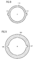
- FIG. 9 a cut view through the first pre-combustion chamber part 170 taken along line IX - IX of Fig. 7 is illustrated.
- the second pre-combustion chamber part 180 is hidden in Fig. 9 .
- the first annular protrusion 174 includes the first and second radially projecting juts 176, 177 on opposite sides.
- first and second grooves 186, 187 have a shape and are arranged such that the first and second grooves 186, 187 are engageable with the first and second juts 176, 177.
- the first and second annular protrusions 174, 184 are rotated such that the positioning device 90 rotatably locks the first and second pre-combustion chamber parts 170, 180 to one another.
- the dimensions of the first and second juts 176, 177 and of the first and second grooves 186, 187 are selected in a manner, such that the axial and radial clearances of the first and second pre-combustion chamber parts 170, 180 mounted to one another is at a minimum.
- the at least one jut 176, 177 may be provided at the second annular protrusion 184, whereas the at least one groove 186, 187 may be provided at the first annular protrusion 174.
- the positioning device 90 may be provided at an interface between an outer peripheral side of the first annular portustion 74 and an inner peripheral side of the second annular protrusion 84 or between an inner peripheral side of the first annular portustion 74 and an outer peripheral side of the second annular protrusion 84.
- the second pre-combustion chamber part 80 may be configured to define and include the entire pre-combustion chamber 68.
- the first pre-combustion chamber part 70 may neither define nor include a portion of the pre-combustion chamber 68, such that the interface between the first and second pre-combustion chamber parts 70, 80 and, hence, the positioning device 90 may be located at an more upper portion of the ignition device 60 in Figs. 3 to 7 , for example, above the pre-combustion chamber 68 at an axial position in the vicinity of the stepped bore 64.
- a separate sealing member 67 may not be necessary, as the pre-combustion chamber 68 is completely provided within the second pre-combustion chamber part 80 and sealed via, for example, the spark plug 62 sealingly received by the spark plug mounting bore 66.
- the spark plug mounting bore 66 may also be provided at the second-pre-combustion chamber part 80, which may also define at least a portion of the fuel supply connection 150.
- the positioning device 90 includes a locking element 92 movable within a first recess 93 provided, for example, in the first pre-combustion chamber part 70 at the first end flange 72.
- the locking element 92 is a spherical element movable within the first recess 93 constituted by, for example, a bore.
- the locking element 92 is configured to at least partially project out of the first recess 93 and to be pre-stressed in a direction out of the first recess 93 by a tensioning member 94, such as, for example, a spiral spring disposed within the first recess 93.
- a second recess 96 is provided in the second end portion 89 of the second pre-combustion chamber part 80 at a position opposite to the locking element 92.
- the second recess 96 has a shape substantially matching with the locking element 92 and is configured to at least partially receive the locking element 92 when the first and second pre-combustion chamber parts 70, 80 are assembled.
- the second recess 96 includes a semispherical shape corresponding to the spherical shape of the locking element 92.
- the first recess 93 may include a caulked opening 98 configured to restrict the locking element 92 to fall out of the first recess 93.
- the caulked opening 98 may be obtained by, for example, hammering or pressing against the opening 98, thereby at least locally reducing the diameter of the opening 98.
- the locking element 92 is provided as a conical element at least partially projecting out of the first recess 93. Also in Fig. 11 , the locking element 92 is pre-stressed by a tensioning member 94, such as, for instance, a spiral spring.
- the second recess 96 is a conical recess substantially matching with the conical locking element 92.
- the locking element 92 is at least partially received by the second recess 96, thereby restricting relative rotational movements between the first and second pre-combustion chamber parts 70, 80.
- the locking element 92 is provided as a conical element having a stick 95 integrally extending from the locking element 92 in a direction towards the bottom of the first recess 93.
- the tensioning member 94 such as, for example, a spiral spring, is disposed about the stick 95 and abuts against the locking element 92 for pre-stressing the locking element 92 in a direction out of the first recess 93.
- the positioning device 90 may be located at any suitable position, such as the positions, shown in Figs. 3 to 6 .
- the locking element 92, the first recess 93, and the tensioning member 94 may be alternatively provided in the second pre-combustion chamber part 80.
- the second recess 96 at least partially receiving the locking element 92 may be provided in the first pre-combustion chamber part 70.
- the plurality of orifices 83 need to have a predetermined orientation with respect to, for example, the inlet and outlet valves 30.
- the fastening device 61 may press the first and second pre-combustion chamber parts 70, 80 in a downward direction (see Fig. 2 ) against the flange 114.
- the first and second pre-combustion chamber parts 70, 80 may need to be pre-assembled. In the pre-assembling, pre-positioning of the first and second pre-combustion chamber parts 70, 80 to one another may be desired.
- the first and second pre-combustion chamber parts 70, 80 are mounted to each other by bringing the first and second threads 76, 86 into engagement. Then, with continuous screwing of the first and second pre-combustion chamber parts 70, 80, the first and second threads 76, 86 disengage each other, such that the first and second threads 76, 86 are at least partially located in the first and second thread undercuts 78, 88, respectively. In this position, the first and second pre-combustion chamber parts 70, 80 are freely rotatable to each other.
- the positioning device 90 may rotationally lock the first and second pre-combustion chamber parts 70, 80 when the locking element 92 engages the second recess 96.
- the ignition device 60 is pre-assembled with the first and second pre-combustion chamber parts 70, 80 relatively positioned to each other. The pre-assembling process may not require any specific tools.
- the pre-assembled ignition device 60 is installed in the cylinder head 24 and fastened thereto by the fastening device 61.
- the second pre-combustion chamber part 80 having the orifices 83 ignition device 60 may be worn and may need to be replaced by a newly pre-combustion chamber part.
- the ignition device 60 is de-installed from the cylinder head 24.
- the second pre-combustion chamber part 80 may easily be screwed off the first pre-combustion chamber part 70 by hand without requiring any specific tools.
- a new second pre-combustion chamber part may be mounted to the first pre-combustion chamber part 70 as set out above, also by easily screwing the second pre-combustion chamber part 80 onto the second pre-combustion chamber part 80 and automatically locking the first and second pre-combustion chamber parts 70, 80 to one another.
- the first and second threads 76, 86 of the first and second pre-combustion chamber parts 70, 80, respectively, may have a standard configuration, such as, for example, a metric configuration. Hence, the first and second threads 76, 86 may not need to have a specific configuration. Additionally, in some embodiments, it might be sufficient that the first and second threads 76, 86 may have one convolution. In some embodiments, providing the first and second threads 76, 78 with a portion of a single convolution (for example, a quarter convolution) might be sufficient to assure axial locking of the first and second pre-combustion chamber parts 70, 80.
- the first annular protrusion 174 is inserted into the second annular protrusion 184, such that the first and second juts 176, 177 engage the first and second grooves 186, 187, respectively.
- the second annular protrusion 184 is axially moved along the longitudinal axis 63 until the first and second juts 176, 177 get out of engagement with the first and second grooves 186, 187, respectively.
- the first and second pre-combustion chamber parts 170, 180 are rotated to one another, until the desired position is reached and the positioning device 90 rotatably locks the first and second pre-combustion chamber parts 170, 180 to one another.
- the pre-combustion chamber part disclosed herein may be provided with a locking device configured to axially secure the first and second pre-combustion chamber parts 70, 80, 170, 180 to one another.
- a locking device configured to axially secure the first and second pre-combustion chamber parts 70, 80, 170, 180 to one another.
- the first and second threads 76, 86 may constitute the axial locking device.
- the bayonet of Fig. 7 may constitute the axial locking device.
Landscapes
- Engineering & Computer Science (AREA)
- Chemical & Material Sciences (AREA)
- Combustion & Propulsion (AREA)
- Mechanical Engineering (AREA)
- General Engineering & Computer Science (AREA)
- Manufacturing & Machinery (AREA)
- Chemical Kinetics & Catalysis (AREA)
- General Chemical & Material Sciences (AREA)
- Oil, Petroleum & Natural Gas (AREA)
- Ignition Installations For Internal Combustion Engines (AREA)
- Cylinder Crankcases Of Internal Combustion Engines (AREA)
Description
- The present disclosure relates to an ignition device for an internal combustion engine. Additionally, the present disclosure relates to a pre-combustion chamber part of an ignition device.
- Internal combustion engines running at least in part on gaseous fuel usually need an ignition device to ignite the mixture of gaseous fuel and air. An ignition device including a pre-combustion chamber may have a spark plug partially protruding into the pre-combustion chamber. Such an ignition device may further include a fuel supply for supplying some amount of gaseous fuel into the pre-combustion chamber. Upon ignition of the mixture of gaseous fuel and air within the pre-combustion chamber, the flames may advance through orifices provided in the pre-combustion chamber into the main combustion chamber, where the flames may ignite the main amount of gaseous fuel and air for operating the internal combustion engine.
- For example,
US 2012/0103302 A1 discloses an ignition system for an internal combustion engine having at least one combustion chamber where the ignition system includes a housing, an ignition device, an injector, and a pre-chamber having a nozzle disposed spaced from the proximal portion of the pre-chamber. The pre-chamber nozzle has an external thread that engages with an internal thread of the proximal portion. - The present disclosure is directed, at least in part, to improving or overcoming one or more aspects of prior systems.
- According to an aspect of the present disclosure, an ignition device according to
claim 1 is disclosed, and an ignition device according to claim 5 is disclosed. - According to a further aspect of the present disclosure, a pre-combustion chamber part according to claim 9 is disclosed, and a pre-combustion chamber part according to
claim 10 is disclosed. - In some embodiments, the pre-combustion chamber part may comprise a positioning device provided at the annular protrusion. The positioning device may be configured to, when the pre-combustion chamber part is in a pre-determined position with respect to the other pre-combustion chamber part, inhibit rotational movement of the second pre-combustion chamber part relative to the first pre-combustion chamber part.
- In some embodiments, the first pre-combustion chamber part may define at least a portion of the pre-combustion chamber.
- In some embodiments, the second pre-combustion chamber part may define the entire pre-combustion chamber. In such embodiments, the first pre-combustion chamber part may neither define nor include a portion of the pre-combustion chamber.
- Other features and aspects of this disclosure will be apparent from the following description and the accompanying drawings.
-
-
Fig. 1 is a diagrammatic cross-sectional view of an internal combustion engine with an ignition device of the present disclosure shown installed in a cylinder head of the internal combustion engine; -
Fig. 2 is a diagrammatic cross-sectional view of the ignition device ofFig. 1 shown in greater detail; -
Fig. 3 is a diagrammatic, partial cut view of a first embodiment of the ignition device according to the present disclosure; -
Fig. 4 is a diagrammatic, partial cut view of another embodiment of the ignition device according to the present disclosure; -
Fig. 5 is a diagrammatic, partial cut view of another embodiment of the ignition device according to the present disclosure; -
Fig. 6 is a diagrammatic, partial cut view of another embodiment of the ignition device according to the present disclosure; -
Fig. 7 is a diagrammatic, partial cut view of another embodiment of the ignition device according to the present disclosure; -
Fig. 8 is a cut view through a first pre-combustion chamber part taken along line XIII - XIII ofFig. 7 ; -
Fig. 9 is a cut view through a second pre-combustion chamber part taken along line IX - IX ofFig. 7 ; -
Fig. 10 is a detailed view of a first embodiment of a positioning device of the ignition device ofFigs. 3 and4 shown in greater detail; -
Fig. 11 is a detailed view of another embodiment of the positioning device shown in greater detail; and -
Fig. 12 is a detailed view of another embodiment of the positioning device shown in greater detail. - The following is a detailed description of exemplary embodiments of the present disclosure. The exemplary embodiments described therein and illustrated in the drawings are intended to teach the principles of the present disclosure, enabling those of ordinary skill in the art to implement and use the present disclosure in many different environments and for many different applications. Therefore, the exemplary embodiments are not intended to be, and should not be considered as, a limiting description of the scope of patent protection. Rather, the scope of patent protection shall be defined by the appended claims.
- The present disclosure may be based at least in part on the realization that an ignition device can be assembled and disassembled without the need of a separate tool. Particularly, providing first and second pre-combustion chamber parts assembled together for forming the ignition device via, for instance, engageable threads or a bayonet may provide the possibility to assemble and disassemble the ignition device without a specific tool. Further, when disassembling the ignition device, it may be assured that the single parts of the ignition device may not be damaged and, thus, some parts of the ignition device may be re-used. This may be especially advantageous in a maintenance event when, for example, the pre-combustion chamber part protruding into the main combustion chamber is attrited. For example, the disclosed ignition device may assure that the pre-combustion chamber part including the pre-combustion chamber tip may remain at the ignition device, also when forcibly detaching the ignition device from the cylinder head.
- The present disclosure may be based at least in part on the realization that two pre-combustion chamber parts of an ignition device can be pre-assembled, such that the two pre-combustion chamber parts are axially secured to each other and rotational movement between the two pre-combustion chamber parts can be inhibited. After pre-assembling, the ignition device may be installed in the cylinder head in a desired position and with a desired orientation of the orifices provided at the ignition device and configured to fluidly connect the pre-combustion chamber with the main combustion chamber.
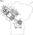
- Referring now to the drawings, an exemplary embodiment of an
internal combustion engine 10 is illustrated inFig. 1 . Theinternal combustion engine 10 may include features not shown, such as fuel systems, air systems, cooling systems, peripheries, drivetrain components, turbochargers, etc. For the purposes of the present disclosure, theinternal combustion engine 10 is considered a four-stroke gaseous fuel internal combustion engine. One skilled in the art will recognize, however, that the gaseous fuelinternal combustion engine 10 may be any type of engine (turbine, gas, diesel, natural gas, propane, etc.) that would utilize a pre-combustion chamber. Furthermore, theinternal combustion engine 10 may be of any size, with any number of cylinders, and in any configuration ("V," in-line, radial, etc.). Theinternal combustion engine 10 may be used to power any machine or other device, including locomotive applications, on-highway trucks or vehicles, off-highway trucks or machines, earth moving equipment, generators, aerospace applications, marine applications, pumps, stationary equipment, or other engine powered applications. - The
internal combustion engine 10 may include anengine block 12 having a plurality of cylinders 14 (one of which is illustrated inFig. 1 ). Apiston 16 may be slidably disposed within thecylinder 14 to reciprocate between a top-dead-center position and a bottom-dead-center position. A connectingrod 18 may connect thepiston 16 to aneccentric crankpin 20 of acrankshaft 22 such that reciprocating motion of the piston may result in rotation of thecrankshaft 22. - The
internal combustion engine 10 may also include acylinder head 24 engaged with theengine block 12 to cover thecylinder 14, thereby delimiting amain combustion chamber 26. Thecylinder head 24 may define intake andexhaust openings 28 that may allow intake gases into themain combustion chamber 26 and exhaust gases out of themain combustion chamber 26, respectively.Engine valves 30 may be positioned to selectively open and close theopenings 28. Eachcylinder 14 may include multiple intake andexhaust openings 28. - The
internal combustion engine 10 may include a series of valve actuation assemblies 40 (one of which is illustrated inFig. 1 ). The multiplevalve actuation assemblies 40 may be provided percylinder 14. For example, one valve actuation assembly may be used to open and close the intake valves and another valve actuation assembly may be provided to open and close the exhaust valves. - The
valve actuation assembly 40 may include arocker arm 46. Therocker arm 46 may be pivotally mounted in thecylinder head 24 and may attach to theengine valves 30 at one end and may attach to apush rod 48 at the other end. Oscillation ofrocker arm 46 about itspivot point 50 may cause thevalves 30 to move between an open position and a closed position. Thevalve actuation assembly 40 may also includevalve springs 52 that may bias thevalves 30 toward the closed position (i.e. closing the intake and exhaust openings 28). - The other end of the
push rod 48 may engage alifter 54 which may engage acamshaft 56. Thecamshaft 56 may operatively engage thecrankshaft 22. Thecamshaft 56 may be connected withcrankshaft 22 in any manner readily apparent to one skilled in the art where rotation of thecrankshaft 22 may result in rotation of thecamshaft 56. For example,camshaft 56 may be connected to crankshaft 22 through a gear train (not shown). - As shown in
Fig. 1 , afirst cam lobe 58 may be disposed on thecamshaft 56 to engage thelifter 54. One skilled in the art may recognize that thecamshaft 56 may include additional cam lobes to engage with other lifters in order to actuate additional engine valves. - The
internal combustion engine 10 may also include an ignition device 60 (also referred to as pre-combustion chamber ignition device), which is positioned within thecylinder head 24 between thevalves 30. Theignition device 60 may be configured in a variety of ways. Any assembly capable of being positioned in thecylinder head 24 to support a combustion event outside of themain combustion chamber 26, and direct the combustion into themain combustion chamber 26 may be used. - With reference to
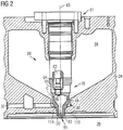
Fig. 2 , theignition device 60 is shown in greater detail. Theignition device 60 defining alongitudinal axis 63 may extend from thecylinder head 24 into themain combustion chamber 26. In the depicted embodiment, theignition device 60 may comprise a firstpre-combustion chamber part 70 and a secondpre-combustion chamber part 80 assembled to the firstpre-combustion chamber part 70. As illustrated inFig. 1 , the firstpre-combustion chamber part 70 is disposed above the secondpre-combustion chamber part 80. InFig. 2 , a separation between the firstpre-combustion chamber part 70 and the secondpre-combustion chamber part 80 is indicated by a dotted line C. - The
ignition device 60 may be attached to thecylinder head 24 via, for example, afastening device 61. In the assembled state, thefastening device 61 may at least partially press theignition device 60 towards the main combustion chamber 26 (inFig. 2 in a downward direction). On the opposite side, theignition device 60 contacts a flange 114, such that the first and secondpre-combustion chamber parts pre-combustion chamber parts pre-combustion chamber part 70 may be generally cylindrical and may be made of any suitable material. - The flange 114 may be sealed against the
main combustion chamber 26. The flange 114 may extend transversely relative to thelongitudinal axis 63 and may be provided to seal against a sealingsurface 116 provided in thecylinder head 24 to prevent leakage between themain combustion chamber 26 and first and second coolingfluid passages - The first
pre-combustion chamber part 70 may be configured to accommodate aspark plug 62 therein such that a sparking end of thespark plug 62 at least partially protrudes into apre-combustion chamber 68 provided within theignition device 60. Thespark plug 62 in the context of this invention may mean any suitable ignition device available in the art. - The second
pre-combustion chamber part 80 may be generally cylindrical and is mountable to the firstpre-combustion chamber part 70, which is described in greater detail with respect toFigs. 3 and4 . Preferably, the secondpre-combustion chamber part 80 may be detachably mountable to the firstpre-combustion chamber part 70. This may allow replacing of the secondpre-combustion chamber part 80 by a new second pre-combustion chamber part in the case of wear of the secondpre-combustion chamber part 80, especially in the case of wear of apre-combustion chamber tip 81 or theorifices 83. For instance, after a usage time of, for example, about 15.000 hours of engine operation, the secondpre-combustion chamber part 80 may be replaced. The secondpre-combustion chamber part 80 may be preferably cast to the general configuration and subsequently machined to final dimensions where required. - The first
pre-combustion chamber part 70 may have a stepped bore 64 that may be adapted to receive thespark plug 62. The stepped bore 64 may have a sparkplug mounting bore 66 adapted to receive an end of thespark plug 62. The sparkplug mounting bore 66 may include a thread adapted to mate with threads on the end of thespark plug 62. The stepped bore 64 may define a sealingsurface 65 that may be adapted to sealingly contact thespark plug 62. - Referring to
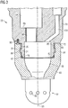
Fig. 3 , a detailed partial cut view of theignition device 60 is illustrated. The secondpre-combustion chamber part 80 includes apre-combustion chamber tip 81 which is generally cylindrical and which may at least partially protrude into themain combustion chamber 26 through a bore 120 provided in thecylinder head 24. - The first
pre-combustion chamber part 70 and the secondpre-combustion chamber part 80 may define apre-combustion chamber 68 disposed therein. The electrode end of thespark plug 62 may at least partially protrude into thepre-combustion chamber 68. - The
pre-combustion chamber tip 81 having a substantially dome-like shape may include a plurality of spaced apart, radially orientedorifices 83. The plurality oforifices 83 may fluidly interconnect thepre-combustion chamber 68 and themain combustion chamber 26 to one another. The plurality oforifices 83 may be configured to direct burning fuel, for example, expanding gases from thepre-combustion chamber 68 in a predetermined pattern into themain combustion chamber 26 and to direct an air/fuel mixture from themain combustion chamber 26 into thepre-combustion chamber 68. - The second
pre-combustion chamber part 80 may be made from a high temperature material. For example, a high temperature, thermally stable and environmentally resistant alloy, such as, a nickel-chromium-tungsten-molybdenum alloy may be suitable. It may be understood that other high temperature materials of suitable composition may be substituted without departing from the present disclosure. Thepre-combustion chamber tip 81 may be cast or machined from, for instance, bar stock. - As further shown in
Fig. 3 , the firstpre-combustion chamber part 70 may include afuel supply connection 150 fluidly connected to thepre-combustion chamber 68 and to a fuel system (not explicitly shown in the drawings). Thefuel supply connection 150 may be configured to receive, for example, gaseous fuel and may then supply the gaseous fuel into thepre-combustion chamber 68. Thefuel supply connection 150 may be further configured to accommodate a control valve (not explicitly shown inFig. 3 ) for controlling the supply of the gaseous fuel amount into thepre-combustion chamber 68. - As illustrated in
Fig. 3 , the firstpre-combustion chamber part 70 is detachably mountable to the secondpre-combustion chamber part 80. The firstpre-combustion chamber part 70 has afirst end flange 72 from which a firstannular protrusion 74 extends. The firstannular protrusion 74 delimits at least partially a portion of thepre-combustion chamber 68 therein. Afirst thread 76 and a first thread undercut 78 are provided at an outer circumferential surface of the firstannular protrusion 74. The first thread undercut 78 is proximally located with respect to thefirst end flange 72, whereas thefirst thread 76 is distally located with respect to thefirst end flange 72. The firstannular protrusion 74 further includes afirst end portion 79 facing towards thepre-combustion chamber tip 81. - The second
pre-combustion chamber part 80 has asecond end flange 82 from which a secondannular protrusion 84 extends. The secondannular protrusion 84 delimits at least partially a portion of thepre-combustion chamber 68 therein. Asecond thread 86 and a second thread undercut 88 are provided at an inner circumferential surface of the secondannular protrusion 84. The second thread undercut 88 is proximally located with respect to thesecond end flange 82, whereas thesecond thread 86 is distally located with respect to thesecond end flange 82. The second annular protrusion further includes asecond end portion 89 facing towards the firstpre-combustion chamber part 70. - As depicted in
Fig. 3 , the inner and outer diameters of the firstannular protrusion 74 and the secondannular protrusion 84 are selected, such that the firstannular protrusion 74 is at least partially inserted into the secondannular protrusion 84 and that thefirst thread 76 is engageable with thesecond thread 86. After having the firstpre-combustion chamber part 70 and the secondpre-combustion chamber part 80 assembled, the first andsecond threads first thread 76 is at least partially located in the second thread undercut 88 and that thesecond thread 86 is at least partially located in the first thread undercut 78. In such position, the firstpre-combustion chamber part 70 is freely rotatable with respect to the secondpre-combustion chamber part 80, but axially secured to one another, such that the secondpre-combustion chamber part 80 may not fall off the firstpre-combustion chamber part 70. - The first and
second threads second threads second threads pre-combustion chamber parts ignition device 60 during assembling or disassembling. - For relatively aligning the first
pre-combustion chamber part 70 to the secondpre-combustion chamber part 80, apositioning device 90 is provided at an interface between thefirst end flange 72 of the firstpre-combustion chamber part 70 and thesecond end portion 89 of the secondpre-combustion chamber part 80 facing each other. Particularly, thepositioning device 90 is configured to relatively fix and position the firstpre-combustion chamber part 70 to the secondpre-combustion chamber part 80, such that the firstpre-combustion chamber part 70 is inhibited from rotation relative to the secondpre-combustion chamber part 80. Thepositioning device 90 is described in greater detail below with reference toFigs. 7 to 9 . - For sealing the
pre-combustion chamber 68 at the interface between the firstpre-combustion chamber part 70 and the secondpre-combustion chamber part 80, a sealingmember 67 may be provided. The sealingmember 67 may seal thefirst thread 76 and thesecond thread 86 from thepre-combustion chamber 68. The sealingmember 67 may be a sealing ring formed from steel. - Referring to
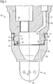
Fig. 4 , another embodiment of theignition device 60 is illustrated. Theignition device 60 ofFig. 4 is substantially identical with theignition device 60 ofFig. 3 , but with thepositioning device 90 provided at an interface between thesecond end flange 82 of the secondpre-combustion chamber part 80 and thefirst end portion 79 of the firstpre-combustion chamber part 70. - With reference to
Fig. 5 , another embodiment of theignition device 60 is illustrated. Theignition device 60 ofFig. 5 is similar to theignition device 60 ofFig. 3 , but differs in that the outer and inner diameters of the first and secondannular protrusions annular protrusion 84 is inserted into the firstannular protrusion 74. In such case, and as shown inFig. 5 , thepositioning device 90 is provided at an interface between thefirst end portion 79 of the firstpre-combustion chamber part 70 and thesecond end flange 82 of the secondpre-combustion chamber part 80. - Referring to
Fig. 6 , another embodiment of theignition device 60 is illustrated. Theignition device 60 ofFig. 6 is substantially identical with theignition device 60 ofFig. 5 , but with thepositioning device 90 provided at an interface between thesecond end portion 89 of the secondpre-combustion chamber part 80 and thefirst end flange 72 of the firstpre-combustion chamber part 70. - With reference to
Fig. 7 , another embodiment of anignition device 160 is illustrated. Theignition device 160 ofFig. 7 is similar to theignition device 60 ofFig. 3 , but includes a bayonet axially locking configuration. Thus, the ignition device ofFig. 7 has different configurations of the first and secondannular protrusions Fig. 7 , the firstannular protrusion 174 includes a firstradially projecting jut 176 and a secondradially projecting jut 177 opposite to the first radially projecting jut. - Referring to
Fig. 8 , a cut view through the secondpre-combustion chamber part 180 taken along line VIII - VIII ofFig. 7 is illustrated. For the sake of clarity, the firstpre-combustion chamber part 170 is hidden inFig. 8 . As can be seen, the secondannular protrusion 184 includes afirst groove 186 and asecond groove 187 opposite to thefirst groove 186. - Referring to
Fig. 9 , a cut view through the firstpre-combustion chamber part 170 taken along line IX - IX ofFig. 7 is illustrated. For the sake of clarity, the secondpre-combustion chamber part 180 is hidden inFig. 9 . As can be seen, the firstannular protrusion 174 includes the first and second radially projectingjuts - With reference to
Figs. 7 to 9 , it can be seen that the first andsecond grooves second grooves second juts - As shown in
Fig. 7 , the first and secondannular protrusions positioning device 90 rotatably locks the first and secondpre-combustion chamber parts second juts second grooves pre-combustion chamber parts - In some embodiments, the at least one
jut annular protrusion 184, whereas the at least onegroove annular protrusion 174. - In some embodiments, referring to
Figs. 3 to 7 , instead of providing thepositioning device 90 at an interface between theend flange 72 and theend portion 89 or between theend flange 82 and theend portion 79, thepositioning device 90 may be provided at an interface between an outer peripheral side of the firstannular portustion 74 and an inner peripheral side of the secondannular protrusion 84 or between an inner peripheral side of the firstannular portustion 74 and an outer peripheral side of the secondannular protrusion 84. - In some embodiments, referring to
Figs. 3 to 7 , the secondpre-combustion chamber part 80 may be configured to define and include the entirepre-combustion chamber 68. In such embodiments, the firstpre-combustion chamber part 70 may neither define nor include a portion of thepre-combustion chamber 68, such that the interface between the first and secondpre-combustion chamber parts positioning device 90 may be located at an more upper portion of theignition device 60 inFigs. 3 to 7 , for example, above thepre-combustion chamber 68 at an axial position in the vicinity of the stepped bore 64. In such embodiments, aseparate sealing member 67 may not be necessary, as thepre-combustion chamber 68 is completely provided within the secondpre-combustion chamber part 80 and sealed via, for example, thespark plug 62 sealingly received by the sparkplug mounting bore 66. In such embodiment, the sparkplug mounting bore 66 may also be provided at the second-pre-combustion chamber part 80, which may also define at least a portion of thefuel supply connection 150. - With respect to
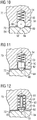
Fig. 10 , a first embodiment of thepositioning device 90 is shown in greater detail. Thepositioning device 90 includes a lockingelement 92 movable within afirst recess 93 provided, for example, in the firstpre-combustion chamber part 70 at thefirst end flange 72. In the embodiment shown inFig. 7 , the lockingelement 92 is a spherical element movable within thefirst recess 93 constituted by, for example, a bore. The lockingelement 92 is configured to at least partially project out of thefirst recess 93 and to be pre-stressed in a direction out of thefirst recess 93 by a tensioningmember 94, such as, for example, a spiral spring disposed within thefirst recess 93. - A
second recess 96 is provided in thesecond end portion 89 of the secondpre-combustion chamber part 80 at a position opposite to the lockingelement 92. Thesecond recess 96 has a shape substantially matching with the lockingelement 92 and is configured to at least partially receive the lockingelement 92 when the first and secondpre-combustion chamber parts Fig. 7 , thesecond recess 96 includes a semispherical shape corresponding to the spherical shape of the lockingelement 92. - As indicated in
Fig. 10 , thefirst recess 93 may include a caulkedopening 98 configured to restrict the lockingelement 92 to fall out of thefirst recess 93. The caulkedopening 98 may be obtained by, for example, hammering or pressing against theopening 98, thereby at least locally reducing the diameter of theopening 98. - Referring now to
Fig. 11 , another embodiment of thepositioning device 90 is illustrated. In the embodiment shown inFig. 11 , the lockingelement 92 is provided as a conical element at least partially projecting out of thefirst recess 93. Also inFig. 11 , the lockingelement 92 is pre-stressed by a tensioningmember 94, such as, for instance, a spiral spring. - In the embodiment shown in
Fig. 11 , thesecond recess 96 is a conical recess substantially matching with theconical locking element 92. When the first and secondpre-combustion chamber parts element 92 is at least partially received by thesecond recess 96, thereby restricting relative rotational movements between the first and secondpre-combustion chamber parts - Referring now to
Fig. 12 , another embodiment of thepositioning device 90 is illustrated. In the embodiment shown inFig. 12 , the lockingelement 92 is provided as a conical element having astick 95 integrally extending from the lockingelement 92 in a direction towards the bottom of thefirst recess 93. The tensioningmember 94, such as, for example, a spiral spring, is disposed about thestick 95 and abuts against the lockingelement 92 for pre-stressing the lockingelement 92 in a direction out of thefirst recess 93. - With respect to
Figs. 10 to 12 , it should be understood that thepositioning device 90 may be located at any suitable position, such as the positions, shown inFigs. 3 to 6 . In this respect, instead of being provided in the firstpre-combustion chamber part 70, the lockingelement 92, thefirst recess 93, and the tensioningmember 94 may be alternatively provided in the secondpre-combustion chamber part 80. In such case, instead of being provided in the secondpre-combustion chamber part 80, thesecond recess 96 at least partially receiving the lockingelement 92 may be provided in the firstpre-combustion chamber part 70. - In the following, an exemplary method for assembling an
ignition device 60 according to the present disclosure is described with respect to the drawings. - When installing the
ignition device 60 into thecylinder head 24, the plurality oforifices 83 need to have a predetermined orientation with respect to, for example, the inlet andoutlet valves 30. For fixing the first and secondpre-combustion chamber parts internal combustion engine 10, thefastening device 61 may press the first and secondpre-combustion chamber parts Fig. 2 ) against the flange 114. However, prior installing theignition device 60 into thecylinder head 24, the first and secondpre-combustion chamber parts pre-combustion chamber parts - With reference to
Figs. 3 to 6 , in a first step, the first and secondpre-combustion chamber parts second threads pre-combustion chamber parts second threads second threads pre-combustion chamber parts - Subsequently, when rotating, for instance, the second
pre-combustion chamber part 80 relative to the firstpre-combustion chamber part 70, thepositioning device 90 may rotationally lock the first and secondpre-combustion chamber parts element 92 engages thesecond recess 96. In this assembling state, theignition device 60 is pre-assembled with the first and secondpre-combustion chamber parts pre-assembled ignition device 60 is installed in thecylinder head 24 and fastened thereto by thefastening device 61. - After a predetermined time of operation of the
internal combustion engine 10, the secondpre-combustion chamber part 80 having theorifices 83ignition device 60 may be worn and may need to be replaced by a newly pre-combustion chamber part. In such a maintenance event, theignition device 60 is de-installed from thecylinder head 24. Then, the secondpre-combustion chamber part 80 may easily be screwed off the firstpre-combustion chamber part 70 by hand without requiring any specific tools. Subsequently, a new second pre-combustion chamber part may be mounted to the firstpre-combustion chamber part 70 as set out above, also by easily screwing the secondpre-combustion chamber part 80 onto the secondpre-combustion chamber part 80 and automatically locking the first and secondpre-combustion chamber parts - The first and
second threads pre-combustion chamber parts second threads second threads second threads pre-combustion chamber parts - When pre-assembling the
ignition device 160 according toFigs. 7 to 9 , in a first step, the firstannular protrusion 174 is inserted into the secondannular protrusion 184, such that the first andsecond juts second grooves annular protrusion 184 is axially moved along thelongitudinal axis 63 until the first andsecond juts second grooves pre-combustion chamber parts positioning device 90 rotatably locks the first and secondpre-combustion chamber parts - In some embodiments, the pre-combustion chamber part disclosed herein may be provided with a locking device configured to axially secure the first and second
pre-combustion chamber parts second threads Fig. 7 may constitute the axial locking device. - Although the preferred embodiments of this invention have been described herein, improvements and modifications may be incorporated without departing from the scope of the following claims.
Claims (13)
- An ignition device (60) with a pre-combustion chamber (68) of an internal combustion engine (10) having a plurality of cylinders (14) each defining a main combustion chamber (26), the ignition device (60) comprising:a first pre-combustion chamber part (70) configured to at least partially accommodate a spark plug (62), the first pre-combustion chamber part (70) including a first end flange (72), and a first annular protrusion (74) extending from the first end flange (72), the first annular protrusion (74) including a first thread (76) provided on a circumferential surface of the first annular protrusion (74); anda second pre-combustion chamber part (80) defining at least a portion of the pre-combustion chamber (68) and including at least one orifice (83) configured to be fluidly connected to the main combustion chamber (26), a second end flange (82), and a second annular protrusion (84) extending from the second end flange (82), the second annular protrusion (84) including a second thread (86) provided on a circumferential surface of the second annular protrusion (84), the first thread (76) being threadably engageable with the second thread (86);wherein one of the first and second annular protrusions (74, 84) at least partially projects into the other one of the first and second annular protrusions (74, 84), characterized in thatthe second pre-combustion chamber part (80) is detachably mounted to the first pre-combustion chamber part (70), such that the first and second pre-combustion chamber parts (70, 80) are axially secured to one another and rotable with respect to one another as, and after the first and second pre-combustion chamber parts (70, 80) are assembled to one another, the first and second threads (76, 86) are out of engagement;
anda positioning device (90) provided at an interface between the first and second pre-combustion chamber parts (70, 80), the positioning device (90) inhibiting, when the first and second pre-combustion chamber parts (70, 80) are assembled to one another and are in a pre-determined position to one another, rotational movement of the second pre-combustion chamber part (80) relative to the first pre-combustion chamber part (70). - The ignition device (60) of claim 1, wherein
the first thread (76) is provided at an outer circumferential surface of the first annular protrusion (74), and
the second thread (86) is provided at an inner circumferential surface of the second annular protrusion (84). - The ignition device (60) of claim 1, wherein
the first thread (76) is provided at an inner circumferential surface of the first annular protrusion (74), and
the second thread (86) is provided at an outer circumferential surface of the second annular protrusion (84). - The ignition device (60) of any one of the preceding claims, wherein
the first annular protrusion (74) includes a first thread undercut (78) adjacent to the first thread (76),
the second annular protrusion (84) includes a second thread undercut (88) adjacent to the second thread (86), and
the first thread (76) at least partially projects into the second thread undercut (88) and/or the second thread (86) at least partially projects into the first thread undercut (78). - An ignition device (160) with a pre-combustion chamber (68) of an internal combustion engine (10) having a plurality of cylinders (14) each defining a main combustion chamber (26), the ignition device (160) comprising:a first pre-combustion chamber part (170) configured to at least partially accommodate a spark plug (62), the first pre-combustion chamber part (70) including a first end flange (72), and a first annular protrusion (174) extending from the first end flange (72), the first annular protrusion (174) including at least one radially projecting jut (176, 177) provided on a circumferential surface of the first annular protrusion (174); anda second pre-combustion chamber part (180) defining at least a portion of the pre-combustion chamber (68) and including at least one orifice (83) configured to be fluidly connected to the main combustion chamber (26), a second end flange (82), and a second annular protrusion (184) extending from the second end flange (82), the second annular protrusion (184) including at least one groove (186, 187) provided in a circumferential surface of the second annular protrusion (184), the at least one radially projecting jut (176, 177) being engageable with the at least one groove (186, 187),wherein one of the first and second annular protrusions (174, 184) at least partially projects into the other one of the first and second annular protrusions (174, 184), characterized in thatthe second pre-combustion chamber part (180) is detachably mountable to the first pre-combustion chamber part (170), such that the first and second pre-combustion chamber parts (170, 180) are axially secured to one another and rotable with respect to one another, and after assembling the first and second pre-combustion chamber parts (170, 180) to one another, the at least one radially projecting jut (176, 177) and the at least one groove (186, 187) are out of engagement,
anda positioning device (90) provided at an interface between the first and second pre-combustion chamber parts (70, 80), the positioning device (90) inhibiting, when the first and second pre-combustion chamber parts (70, 80) are assembled to one another and are in a pre-determined position to one another, rotational movement of the second pre-combustion chamber part (80) relative to the first pre-combustion chamber part (70). - The ignition device (60) of claim 1 or 5, wherein
one of the first and second pre-combustion chamber parts (70, 80) includes a first recess (93) and the other one of the first and second pre-combustion chamber parts (70, 80) includes a second recess (96), and
the positioning device (90) includes a locking element (92) movably positioned within the first recess (93) and at least partially protruding out of the first recess (93), the locking element (92) at least partially matching with the second recess (96). - The ignition device (60) of claim 6, wherein the positioning device (90) further includes at least one tensioning device (94) disposed within the first recess (93) and configured to pre-stress the locking element (92) in a direction out of the first recess (93) and towards the second recess (96), the tensioning device being preferably a spiral spring (94).
- The ignition device (60) of one of claims 6 or 7,
wherein the locking element is a spherical locking element (92) and the second recess is a at least one of a semispherical recess (96) or a conical recess (96) which at least partially matches with the spherical locking element (92), or
wherein the locking element is a conical locking element (92) and the second recess is a conical recess (96) at least partially matching with the conical locking element (92). - A pre-combustion chamber part (80) of the ignition device (60) according to claim 1, the pre-combustion chamber part (80) defining at least a portion of the pre-combustion chamber (68), the pre-combustion chamber part (80) comprising:a plurality of orifices (83) fluidly connecting the pre-combustion chamber (68) with the main combustion chamber (26); andan annular protrusion (84) for connecting to another pre-combustion chamber part (70), the annular protrusion (84) having:a first thread (86) provided on a circumferential surface of the annular protrusion and threadably engageable with a second thread (76) provided on a circumferential surface of an annular protrusion (74) of the other pre-combustion chamber part (70), anda first thread undercut (78) adjacent to the first thread (76),the pre-combustion chamber part (80) being configured to, when the pre-combustion chamber part (80) is mounted to the other pre-combustion chamber part (70), axially secure the pre-combustion chamber part (80) to the other pre-combustion chamber part (70) and to allow for rotational movement of the pre-combustion chamber part (80) with respect to the other pre-combustion chamber part (70).
- A pre-combustion chamber part (170; 180) of the ignition device (60) according to claim 5, the pre-combustion chamber part (170; 180) defining at least a portion of the pre-combustion chamber (68), the pre-combustion chamber part (170; 180) comprising:a plurality of orifices (83) fluidly connecting the pre-combustion chamber (68) with the main combustion chamber (26); andan annular protrusion (174; 184) for connecting to another pre-combustion chamber part (170; 180), the annular protrusion (174; 184) having :at least one radially projecting jut (176, 177) provided on a circumferential surface of the annular protrusion (174), the at least one radially projecting jut (176, 177) being engageable with at least one groove (186, 187) provided in a circumferential surface of the other pre-combustion chamber part (170), and an undercut adjacent to the at least one radially projecting jut (176, 177); orat least one groove (186, 187) provided in a circumferential surface of the annular protrusion (174), the at least one least one groove (186, 187) being engageable with at least one radially projecting jut (176, 177) provided on a circumferential surface of an annular protrusion (74) of the other pre-combustion chamber part (70), and an undercut adjacent to the at least one groove (186, 187),the pre-combustion chamber part (170; 180) being configured to, when the pre-combustion chamber part (170; 180) is mounted to the other pre-combustion chamber part (170; 180), axially secure the pre-combustion chamber part (170; 180) to the other pre-combustion chamber part (170; 180) and to allow for rotational movement of the pre-combustion chamber part (170; 80) with respect to the other pre-combustion chamber part (170; 180).
- The pre-combustion chamber part (80; 180) of claim 10 or 11, further comprising a positioning device (90) provided at the annular protrusion (84; 184) and configured to, when the pre-combustion chamber part (80; 180) is in a pre-determined position with respect to the other pre-combustion chamber part (70; 170), inhibit rotational movement of the second pre-combustion chamber part (80; 180) relative to the first pre-combustion chamber part (70; 170).
- The pre-combustion chamber part (80; 180) of claim 11, wherein the positioning device (90) includes:a recess (93) provided in an end portion (89) of the annular protrusion (84), anda locking element (92) movably positioned within the recess (93) and at least partially protruding out of the recess (93), the locking element (92) being configured at least partially engage the other pre-combustion chamber part (70; 170) for inhibiting rotational movement between the pre-combustion chamber part (80; 180) and the other pre-combustion chamber part (70; 170).
- The pre-combustion chamber part (80; 180) of claim 11, wherein the positioning device (90) includes a recess (96) provided in an end portion (89) of the annular protrusion (84) and configured to engage with a locking element (92) configured to be movably positioned within the other pre-combustion chamber part (70; 170) for inhibiting rotational movement between the pre-combustion chamber part (80; 180) and the other pre-combustion chamber part (70; 170).
Priority Applications (3)
| Application Number | Priority Date | Filing Date | Title |
|---|---|---|---|
| EP14178054.4A EP2977582B1 (en) | 2014-07-22 | 2014-07-22 | Ignition device with pre-combustion chamber |
| US14/801,106 US9732664B2 (en) | 2014-07-22 | 2015-07-16 | Ignition device with pre-combustion chamber |
| CN201510431258.1A CN105298624B (en) | 2014-07-22 | 2015-07-21 | Igniter with precombustion chamber |
Applications Claiming Priority (1)
| Application Number | Priority Date | Filing Date | Title |
|---|---|---|---|
| EP14178054.4A EP2977582B1 (en) | 2014-07-22 | 2014-07-22 | Ignition device with pre-combustion chamber |
Publications (2)
| Publication Number | Publication Date |
|---|---|
| EP2977582A1 EP2977582A1 (en) | 2016-01-27 |
| EP2977582B1 true EP2977582B1 (en) | 2018-03-28 |
Family
ID=51211686
Family Applications (1)
| Application Number | Title | Priority Date | Filing Date |
|---|---|---|---|
| EP14178054.4A Active EP2977582B1 (en) | 2014-07-22 | 2014-07-22 | Ignition device with pre-combustion chamber |
Country Status (3)
| Country | Link |
|---|---|
| US (1) | US9732664B2 (en) |
| EP (1) | EP2977582B1 (en) |
| CN (1) | CN105298624B (en) |
Cited By (1)
| Publication number | Priority date | Publication date | Assignee | Title |
|---|---|---|---|---|
| DE102020126695A1 (en) | 2020-10-12 | 2022-04-14 | Bayerische Motoren Werke Aktiengesellschaft | Ignition device with a prechamber coupled to an ignition source so that it can rotate without offset, internal combustion engine with an ignition device and motor vehicle with an internal combustion engine |
Families Citing this family (17)
| Publication number | Priority date | Publication date | Assignee | Title |
|---|---|---|---|---|
| JP2015117582A (en) * | 2013-12-16 | 2015-06-25 | 三菱重工業株式会社 | Gas engine and assembling method of gas engine |
| US20170138251A1 (en) * | 2015-11-12 | 2017-05-18 | Cummins Inc. | Pre-chamber nozzle |
| US10662865B2 (en) * | 2016-08-31 | 2020-05-26 | Caterpillar Inc. | Method of remanufacturing a prechamber assembly |
| US10641159B2 (en) * | 2016-09-23 | 2020-05-05 | Caterpillar Inc. | Pre-chamber assembly for fuel injector |
| US10184387B2 (en) * | 2017-01-27 | 2019-01-22 | Caterpillar Inc. | Remanufactured prechamber device and method |
| JP6824801B2 (en) * | 2017-03-31 | 2021-02-03 | 本田技研工業株式会社 | Sub-chamber structure of internal combustion engine |
| CN107246345A (en) * | 2017-07-03 | 2017-10-13 | 芜湖市海联机械设备有限公司 | A kind of high temperature resistant nozzle |
| JP6958087B2 (en) * | 2017-08-03 | 2021-11-02 | 株式会社デンソー | Ignition coil and connection structure between ignition coil and spark plug |
| EP3735523A4 (en) * | 2018-01-05 | 2021-09-15 | Cummins, Inc. | Combustion pre-chamber device for an internal combustion engine |
| JP7257236B2 (en) * | 2019-04-22 | 2023-04-13 | 三菱重工エンジン&ターボチャージャ株式会社 | pre-chamber engine |
| CN110725765B (en) * | 2019-07-15 | 2022-02-11 | 天津大学 | Jet igniter of water-cooled engine |
| GB2595730B (en) * | 2020-06-05 | 2022-11-23 | Caterpillar Energy Solutions Gmbh | Pre-combustion chamber assembly |
| CN113944540B (en) * | 2020-07-17 | 2023-02-28 | 广州汽车集团股份有限公司 | Engine pre-combustion chamber structure, engine and automobile with engine pre-combustion chamber structure |
| DE102020133717A1 (en) | 2020-12-16 | 2022-06-23 | Bayerische Motoren Werke Aktiengesellschaft | Ignition device with a prechamber coupled to an ignition source so that it can rotate without offset, internal combustion engine with an ignition device and motor vehicle with an internal combustion engine |
| US11512677B1 (en) | 2022-03-08 | 2022-11-29 | Fca Us Llc | Pre-chamber jet ignition torque control with two ignition sources |
| US11686251B1 (en) | 2022-04-26 | 2023-06-27 | Fca Us Llc | Pre-chamber spark control with two ignition sources |
| CN115401449B (en) * | 2022-08-15 | 2024-01-16 | 中国第一汽车股份有限公司 | Method for assembling and disassembling precombustion chamber of engine |
Family Cites Families (18)
| Publication number | Priority date | Publication date | Assignee | Title |
|---|---|---|---|---|
| CS212763B2 (en) * | 1975-05-22 | 1982-03-26 | Bosch Gmbh Robert | Internal combustion engine |
| DE3230793A1 (en) * | 1982-08-19 | 1984-02-23 | Robert Bosch Gmbh, 7000 Stuttgart | Ignition device for internal combustion engines |
| US5203298A (en) | 1992-05-29 | 1993-04-20 | John Manolis | Pre-combustion chamber for internal combustion engine |
| US5662082A (en) * | 1995-12-05 | 1997-09-02 | Compressor Engineering Corporation | Pre-combustion chamber for internal combustion engine and method of manufacture thereof |
| US5915351A (en) * | 1997-02-24 | 1999-06-29 | Chrysler Corporation | Insulated precombustion chamber |
| US6016785A (en) | 1998-10-01 | 2000-01-25 | Caterpillar Inc. | Pre-combustion chamber assembly and method |
| NO322345B1 (en) * | 2004-09-27 | 2006-09-18 | Rolls Royce Marine As | Device at a front chamber of a gas engine |
| US7270107B2 (en) | 2006-01-20 | 2007-09-18 | Cameron International Corporation | Bolted pre-combustion chamber |
| US20070236122A1 (en) * | 2006-04-10 | 2007-10-11 | Borror Bruce M | Pre-chamber type spark plug |
| US8104444B2 (en) * | 2007-10-31 | 2012-01-31 | Caterpillar Inc. | Pre-chamber igniter having RF-aided spark initiation |
| FI125706B (en) | 2010-02-22 | 2016-01-15 | Wärtsilä Finland Oy | THE COMBUSTION ENGINE OF THE COMBUSTION ENGINE |
| US8857405B2 (en) * | 2010-11-01 | 2014-10-14 | Mahle Powertrain, Llc | Turbulent jet ignition pre-chamber combustion system for spark ignition engines |
| AT510869B1 (en) * | 2010-12-27 | 2013-04-15 | Ge Jenbacher Gmbh & Co Ohg | Internal combustion engine |
| US8350457B2 (en) | 2011-03-31 | 2013-01-08 | Denso International America, Inc. | Pre-chamber spark plug including a gas thread cavity |
| DE102011101400B4 (en) * | 2011-05-13 | 2013-02-07 | Iav Gmbh Ingenieurgesellschaft Auto Und Verkehr | Valve train for internal combustion engines for actuating gas exchange valves |
| KR101307080B1 (en) * | 2011-07-19 | 2013-09-11 | 현대중공업 주식회사 | Pre combustion chamber for gas engine |
| US9217360B2 (en) * | 2011-12-01 | 2015-12-22 | Cummins Intellectual Property, Inc. | Prechamber device for internal combustion engine |
| EP2700796B1 (en) * | 2012-08-22 | 2016-08-10 | Caterpillar Motoren GmbH & Co. KG | Pre-combustion chamber of an internal combustion engine and method of operating the same |
-
2014
- 2014-07-22 EP EP14178054.4A patent/EP2977582B1/en active Active
-
2015
- 2015-07-16 US US14/801,106 patent/US9732664B2/en active Active
- 2015-07-21 CN CN201510431258.1A patent/CN105298624B/en active Active
Non-Patent Citations (1)
| Title |
|---|
| None * |
Cited By (1)
| Publication number | Priority date | Publication date | Assignee | Title |
|---|---|---|---|---|
| DE102020126695A1 (en) | 2020-10-12 | 2022-04-14 | Bayerische Motoren Werke Aktiengesellschaft | Ignition device with a prechamber coupled to an ignition source so that it can rotate without offset, internal combustion engine with an ignition device and motor vehicle with an internal combustion engine |
Also Published As
| Publication number | Publication date |
|---|---|
| US20160024995A1 (en) | 2016-01-28 |
| CN105298624A (en) | 2016-02-03 |
| EP2977582A1 (en) | 2016-01-27 |
| US9732664B2 (en) | 2017-08-15 |
| CN105298624B (en) | 2019-08-30 |
Similar Documents
| Publication | Publication Date | Title |
|---|---|---|
| EP2977582B1 (en) | Ignition device with pre-combustion chamber | |
| CN105525981B (en) | Pre-combustion chamber assembly for internal combustion engine | |
| EP2700796B1 (en) | Pre-combustion chamber of an internal combustion engine and method of operating the same | |
| EP3118433B1 (en) | Pre-combustion chamber assembly for internal combustion engines | |
| EP2573355B1 (en) | Pre-combustion chamber tip | |
| EP3051092B1 (en) | Cooling of pre-chamber in internal combustion engine | |
| EP2935865B1 (en) | Ignition plug tip of an internal combustion engine | |
| US10938185B1 (en) | Spark plug assembly for an internal combustion engine | |
| JP4696092B2 (en) | Decompression device for internal combustion engine | |
| EP3817888B1 (en) | Apparatus and method for positioning a connecting rod relative to one or more components underlying a cylinder of an engine block | |
| EP3191694B1 (en) | Method of remanufacturing a rocker arm and rocker arm | |
| US7198023B1 (en) | Sequential injection lubrication system for a spherical rotary valve internal combustion engine operating on natural gas or alternative fuels | |
| CN112963218A (en) | Valve structure, valve mechanism and engine | |
| EP2031194B1 (en) | Assembled camshaft for exhaust gas recirculation system | |
| US20190277221A1 (en) | Thermally compensated bore guide systems and methods | |
| CN103925096A (en) | Integrated engine body | |
| JP7082523B2 (en) | Heat shield film member | |
| KR100412877B1 (en) | Auto knock bushing structure in automotive engine | |
| US20150101559A1 (en) | Button for rocker arm assembly | |
| JP5312872B2 (en) | engine | |
| JPH07139315A (en) | Valve system of engine | |
| JP2006348768A (en) | Shaft support structure | |
| WO2021019691A1 (en) | Thermal insulation film member | |
| KR20080045555A (en) | Check valve for cooling piston | |
| KR200338436Y1 (en) | Cylinder head |
Legal Events
| Date | Code | Title | Description |
|---|---|---|---|
| PUAI | Public reference made under article 153(3) epc to a published international application that has entered the european phase |
Free format text: ORIGINAL CODE: 0009012 |
|
| AK | Designated contracting states |
Kind code of ref document: A1 Designated state(s): AL AT BE BG CH CY CZ DE DK EE ES FI FR GB GR HR HU IE IS IT LI LT LU LV MC MK MT NL NO PL PT RO RS SE SI SK SM TR |
|
| AX | Request for extension of the european patent |
Extension state: BA ME |
|
| 17P | Request for examination filed |
Effective date: 20160727 |
|
| RBV | Designated contracting states (corrected) |
Designated state(s): AL AT BE BG CH CY CZ DE DK EE ES FI FR GB GR HR HU IE IS IT LI LT LU LV MC MK MT NL NO PL PT RO RS SE SI SK SM TR |
|
| 17Q | First examination report despatched |
Effective date: 20161208 |
|
| RIC1 | Information provided on ipc code assigned before grant |
Ipc: F02M 57/06 20060101ALI20170714BHEP Ipc: F02M 21/02 20060101ALI20170714BHEP Ipc: F02M 61/16 20060101ALI20170714BHEP Ipc: F02B 19/10 20060101AFI20170714BHEP Ipc: F02P 13/00 20060101ALI20170714BHEP Ipc: F02B 19/16 20060101ALI20170714BHEP Ipc: F02B 19/12 20060101ALI20170714BHEP |
|
| GRAP | Despatch of communication of intention to grant a patent |
Free format text: ORIGINAL CODE: EPIDOSNIGR1 |
|
| INTG | Intention to grant announced |
Effective date: 20171009 |
|
| GRAS | Grant fee paid |
Free format text: ORIGINAL CODE: EPIDOSNIGR3 |
|
| GRAA | (expected) grant |
Free format text: ORIGINAL CODE: 0009210 |
|
| AK | Designated contracting states |
Kind code of ref document: B1 Designated state(s): AL AT BE BG CH CY CZ DE DK EE ES FI FR GB GR HR HU IE IS IT LI LT LU LV MC MK MT NL NO PL PT RO RS SE SI SK SM TR |
|
| REG | Reference to a national code |
Ref country code: GB Ref legal event code: FG4D |
|
| REG | Reference to a national code |
Ref country code: CH Ref legal event code: EP |
|
| REG | Reference to a national code |
Ref country code: AT Ref legal event code: REF Ref document number: 983655 Country of ref document: AT Kind code of ref document: T Effective date: 20180415 |
|
| REG | Reference to a national code |
Ref country code: IE Ref legal event code: FG4D |
|
| REG | Reference to a national code |
Ref country code: DE Ref legal event code: R096 Ref document number: 602014022897 Country of ref document: DE |
|
| REG | Reference to a national code |
Ref country code: FR Ref legal event code: PLFP Year of fee payment: 5 |
|
| PG25 | Lapsed in a contracting state [announced via postgrant information from national office to epo] |
Ref country code: HR Free format text: LAPSE BECAUSE OF FAILURE TO SUBMIT A TRANSLATION OF THE DESCRIPTION OR TO PAY THE FEE WITHIN THE PRESCRIBED TIME-LIMIT Effective date: 20180328 Ref country code: NO Free format text: LAPSE BECAUSE OF FAILURE TO SUBMIT A TRANSLATION OF THE DESCRIPTION OR TO PAY THE FEE WITHIN THE PRESCRIBED TIME-LIMIT Effective date: 20180628 Ref country code: FI Free format text: LAPSE BECAUSE OF FAILURE TO SUBMIT A TRANSLATION OF THE DESCRIPTION OR TO PAY THE FEE WITHIN THE PRESCRIBED TIME-LIMIT Effective date: 20180328 Ref country code: LT Free format text: LAPSE BECAUSE OF FAILURE TO SUBMIT A TRANSLATION OF THE DESCRIPTION OR TO PAY THE FEE WITHIN THE PRESCRIBED TIME-LIMIT Effective date: 20180328 |
|
| REG | Reference to a national code |
Ref country code: NL Ref legal event code: MP Effective date: 20180328 |
|
| REG | Reference to a national code |
Ref country code: LT Ref legal event code: MG4D |
|
| PG25 | Lapsed in a contracting state [announced via postgrant information from national office to epo] |
Ref country code: RS Free format text: LAPSE BECAUSE OF FAILURE TO SUBMIT A TRANSLATION OF THE DESCRIPTION OR TO PAY THE FEE WITHIN THE PRESCRIBED TIME-LIMIT Effective date: 20180328 Ref country code: LV Free format text: LAPSE BECAUSE OF FAILURE TO SUBMIT A TRANSLATION OF THE DESCRIPTION OR TO PAY THE FEE WITHIN THE PRESCRIBED TIME-LIMIT Effective date: 20180328 Ref country code: SE Free format text: LAPSE BECAUSE OF FAILURE TO SUBMIT A TRANSLATION OF THE DESCRIPTION OR TO PAY THE FEE WITHIN THE PRESCRIBED TIME-LIMIT Effective date: 20180328 Ref country code: BG Free format text: LAPSE BECAUSE OF FAILURE TO SUBMIT A TRANSLATION OF THE DESCRIPTION OR TO PAY THE FEE WITHIN THE PRESCRIBED TIME-LIMIT Effective date: 20180628 Ref country code: GR Free format text: LAPSE BECAUSE OF FAILURE TO SUBMIT A TRANSLATION OF THE DESCRIPTION OR TO PAY THE FEE WITHIN THE PRESCRIBED TIME-LIMIT Effective date: 20180629 |
|
| PG25 | Lapsed in a contracting state [announced via postgrant information from national office to epo] |
Ref country code: AL Free format text: LAPSE BECAUSE OF FAILURE TO SUBMIT A TRANSLATION OF THE DESCRIPTION OR TO PAY THE FEE WITHIN THE PRESCRIBED TIME-LIMIT Effective date: 20180328 Ref country code: RO Free format text: LAPSE BECAUSE OF FAILURE TO SUBMIT A TRANSLATION OF THE DESCRIPTION OR TO PAY THE FEE WITHIN THE PRESCRIBED TIME-LIMIT Effective date: 20180328 Ref country code: IT Free format text: LAPSE BECAUSE OF FAILURE TO SUBMIT A TRANSLATION OF THE DESCRIPTION OR TO PAY THE FEE WITHIN THE PRESCRIBED TIME-LIMIT Effective date: 20180328 Ref country code: PL Free format text: LAPSE BECAUSE OF FAILURE TO SUBMIT A TRANSLATION OF THE DESCRIPTION OR TO PAY THE FEE WITHIN THE PRESCRIBED TIME-LIMIT Effective date: 20180328 Ref country code: EE Free format text: LAPSE BECAUSE OF FAILURE TO SUBMIT A TRANSLATION OF THE DESCRIPTION OR TO PAY THE FEE WITHIN THE PRESCRIBED TIME-LIMIT Effective date: 20180328 Ref country code: NL Free format text: LAPSE BECAUSE OF FAILURE TO SUBMIT A TRANSLATION OF THE DESCRIPTION OR TO PAY THE FEE WITHIN THE PRESCRIBED TIME-LIMIT Effective date: 20180328 Ref country code: ES Free format text: LAPSE BECAUSE OF FAILURE TO SUBMIT A TRANSLATION OF THE DESCRIPTION OR TO PAY THE FEE WITHIN THE PRESCRIBED TIME-LIMIT Effective date: 20180328 |
|
| PG25 | Lapsed in a contracting state [announced via postgrant information from national office to epo] |
Ref country code: SM Free format text: LAPSE BECAUSE OF FAILURE TO SUBMIT A TRANSLATION OF THE DESCRIPTION OR TO PAY THE FEE WITHIN THE PRESCRIBED TIME-LIMIT Effective date: 20180328 Ref country code: SK Free format text: LAPSE BECAUSE OF FAILURE TO SUBMIT A TRANSLATION OF THE DESCRIPTION OR TO PAY THE FEE WITHIN THE PRESCRIBED TIME-LIMIT Effective date: 20180328 Ref country code: CZ Free format text: LAPSE BECAUSE OF FAILURE TO SUBMIT A TRANSLATION OF THE DESCRIPTION OR TO PAY THE FEE WITHIN THE PRESCRIBED TIME-LIMIT Effective date: 20180328 |
|
| REG | Reference to a national code |
Ref country code: AT Ref legal event code: MK05 Ref document number: 983655 Country of ref document: AT Kind code of ref document: T Effective date: 20180328 |
|
| PG25 | Lapsed in a contracting state [announced via postgrant information from national office to epo] |
Ref country code: PT Free format text: LAPSE BECAUSE OF FAILURE TO SUBMIT A TRANSLATION OF THE DESCRIPTION OR TO PAY THE FEE WITHIN THE PRESCRIBED TIME-LIMIT Effective date: 20180730 |
|
| REG | Reference to a national code |
Ref country code: DE Ref legal event code: R097 Ref document number: 602014022897 Country of ref document: DE |
|
| PG25 | Lapsed in a contracting state [announced via postgrant information from national office to epo] |
Ref country code: DK Free format text: LAPSE BECAUSE OF FAILURE TO SUBMIT A TRANSLATION OF THE DESCRIPTION OR TO PAY THE FEE WITHIN THE PRESCRIBED TIME-LIMIT Effective date: 20180328 Ref country code: AT Free format text: LAPSE BECAUSE OF FAILURE TO SUBMIT A TRANSLATION OF THE DESCRIPTION OR TO PAY THE FEE WITHIN THE PRESCRIBED TIME-LIMIT Effective date: 20180328 |
|
| PLBE | No opposition filed within time limit |
Free format text: ORIGINAL CODE: 0009261 |
|
| STAA | Information on the status of an ep patent application or granted ep patent |
Free format text: STATUS: NO OPPOSITION FILED WITHIN TIME LIMIT |
|
| REG | Reference to a national code |
Ref country code: CH Ref legal event code: PL |
|
| 26N | No opposition filed |
Effective date: 20190103 |
|
| PG25 | Lapsed in a contracting state [announced via postgrant information from national office to epo] |
Ref country code: MC Free format text: LAPSE BECAUSE OF FAILURE TO SUBMIT A TRANSLATION OF THE DESCRIPTION OR TO PAY THE FEE WITHIN THE PRESCRIBED TIME-LIMIT Effective date: 20180328 Ref country code: LU Free format text: LAPSE BECAUSE OF NON-PAYMENT OF DUE FEES Effective date: 20180722 |
|
| REG | Reference to a national code |
Ref country code: BE Ref legal event code: MM Effective date: 20180731 |
|
| REG | Reference to a national code |
Ref country code: IE Ref legal event code: MM4A |
|
| PG25 | Lapsed in a contracting state [announced via postgrant information from national office to epo] |
Ref country code: IE Free format text: LAPSE BECAUSE OF NON-PAYMENT OF DUE FEES Effective date: 20180722 Ref country code: CH Free format text: LAPSE BECAUSE OF NON-PAYMENT OF DUE FEES Effective date: 20180731 Ref country code: LI Free format text: LAPSE BECAUSE OF NON-PAYMENT OF DUE FEES Effective date: 20180731 |
|
| PG25 | Lapsed in a contracting state [announced via postgrant information from national office to epo] |
Ref country code: BE Free format text: LAPSE BECAUSE OF NON-PAYMENT OF DUE FEES Effective date: 20180731 Ref country code: SI Free format text: LAPSE BECAUSE OF FAILURE TO SUBMIT A TRANSLATION OF THE DESCRIPTION OR TO PAY THE FEE WITHIN THE PRESCRIBED TIME-LIMIT Effective date: 20180328 |
|
| PG25 | Lapsed in a contracting state [announced via postgrant information from national office to epo] |
Ref country code: MT Free format text: LAPSE BECAUSE OF NON-PAYMENT OF DUE FEES Effective date: 20180722 |
|
| PG25 | Lapsed in a contracting state [announced via postgrant information from national office to epo] |
Ref country code: TR Free format text: LAPSE BECAUSE OF FAILURE TO SUBMIT A TRANSLATION OF THE DESCRIPTION OR TO PAY THE FEE WITHIN THE PRESCRIBED TIME-LIMIT Effective date: 20180328 |
|
| PG25 | Lapsed in a contracting state [announced via postgrant information from national office to epo] |
Ref country code: MK Free format text: LAPSE BECAUSE OF NON-PAYMENT OF DUE FEES Effective date: 20180328 Ref country code: CY Free format text: LAPSE BECAUSE OF FAILURE TO SUBMIT A TRANSLATION OF THE DESCRIPTION OR TO PAY THE FEE WITHIN THE PRESCRIBED TIME-LIMIT Effective date: 20180328 Ref country code: HU Free format text: LAPSE BECAUSE OF FAILURE TO SUBMIT A TRANSLATION OF THE DESCRIPTION OR TO PAY THE FEE WITHIN THE PRESCRIBED TIME-LIMIT; INVALID AB INITIO Effective date: 20140722 |
|
| PG25 | Lapsed in a contracting state [announced via postgrant information from national office to epo] |
Ref country code: IS Free format text: LAPSE BECAUSE OF FAILURE TO SUBMIT A TRANSLATION OF THE DESCRIPTION OR TO PAY THE FEE WITHIN THE PRESCRIBED TIME-LIMIT Effective date: 20180728 |
|
| P01 | Opt-out of the competence of the unified patent court (upc) registered |
Effective date: 20230517 |
|
| PGFP | Annual fee paid to national office [announced via postgrant information from national office to epo] |
Ref country code: DE Payment date: 20230620 Year of fee payment: 10 |
|
| PGFP | Annual fee paid to national office [announced via postgrant information from national office to epo] |
Ref country code: GB Payment date: 20240620 Year of fee payment: 11 |
|
| PGFP | Annual fee paid to national office [announced via postgrant information from national office to epo] |
Ref country code: FR Payment date: 20240619 Year of fee payment: 11 |