EP2977579A1 - Verbrennungskraftmaschine - Google Patents
Verbrennungskraftmaschine Download PDFInfo
- Publication number
- EP2977579A1 EP2977579A1 EP15002143.4A EP15002143A EP2977579A1 EP 2977579 A1 EP2977579 A1 EP 2977579A1 EP 15002143 A EP15002143 A EP 15002143A EP 2977579 A1 EP2977579 A1 EP 2977579A1
- Authority
- EP
- European Patent Office
- Prior art keywords
- combustion engine
- internal combustion
- catalyst unit
- gas
- measuring device
- Prior art date
- Legal status (The legal status is an assumption and is not a legal conclusion. Google has not performed a legal analysis and makes no representation as to the accuracy of the status listed.)
- Granted
Links
Images

Classifications
-
- F—MECHANICAL ENGINEERING; LIGHTING; HEATING; WEAPONS; BLASTING
- F01—MACHINES OR ENGINES IN GENERAL; ENGINE PLANTS IN GENERAL; STEAM ENGINES
- F01N—GAS-FLOW SILENCERS OR EXHAUST APPARATUS FOR MACHINES OR ENGINES IN GENERAL; GAS-FLOW SILENCERS OR EXHAUST APPARATUS FOR INTERNAL-COMBUSTION ENGINES
- F01N3/00—Exhaust or silencing apparatus having means for purifying, rendering innocuous, or otherwise treating exhaust
- F01N3/08—Exhaust or silencing apparatus having means for purifying, rendering innocuous, or otherwise treating exhaust for rendering innocuous
- F01N3/10—Exhaust or silencing apparatus having means for purifying, rendering innocuous, or otherwise treating exhaust for rendering innocuous by thermal or catalytic conversion of noxious components of exhaust
-
- F—MECHANICAL ENGINEERING; LIGHTING; HEATING; WEAPONS; BLASTING
- F01—MACHINES OR ENGINES IN GENERAL; ENGINE PLANTS IN GENERAL; STEAM ENGINES
- F01N—GAS-FLOW SILENCERS OR EXHAUST APPARATUS FOR MACHINES OR ENGINES IN GENERAL; GAS-FLOW SILENCERS OR EXHAUST APPARATUS FOR INTERNAL-COMBUSTION ENGINES
- F01N3/00—Exhaust or silencing apparatus having means for purifying, rendering innocuous, or otherwise treating exhaust
- F01N3/08—Exhaust or silencing apparatus having means for purifying, rendering innocuous, or otherwise treating exhaust for rendering innocuous
- F01N3/10—Exhaust or silencing apparatus having means for purifying, rendering innocuous, or otherwise treating exhaust for rendering innocuous by thermal or catalytic conversion of noxious components of exhaust
- F01N3/103—Oxidation catalysts for HC and CO only
-
- G—PHYSICS
- G01—MEASURING; TESTING
- G01M—TESTING STATIC OR DYNAMIC BALANCE OF MACHINES OR STRUCTURES; TESTING OF STRUCTURES OR APPARATUS, NOT OTHERWISE PROVIDED FOR
- G01M15/00—Testing of engines
- G01M15/04—Testing internal-combustion engines
- G01M15/10—Testing internal-combustion engines by monitoring exhaust gases or combustion flame
- G01M15/102—Testing internal-combustion engines by monitoring exhaust gases or combustion flame by monitoring exhaust gases
-
- B—PERFORMING OPERATIONS; TRANSPORTING
- B01—PHYSICAL OR CHEMICAL PROCESSES OR APPARATUS IN GENERAL
- B01D—SEPARATION
- B01D53/00—Separation of gases or vapours; Recovering vapours of volatile solvents from gases; Chemical or biological purification of waste gases, e.g. engine exhaust gases, smoke, fumes, flue gases, aerosols
-
- F—MECHANICAL ENGINEERING; LIGHTING; HEATING; WEAPONS; BLASTING
- F01—MACHINES OR ENGINES IN GENERAL; ENGINE PLANTS IN GENERAL; STEAM ENGINES
- F01N—GAS-FLOW SILENCERS OR EXHAUST APPARATUS FOR MACHINES OR ENGINES IN GENERAL; GAS-FLOW SILENCERS OR EXHAUST APPARATUS FOR INTERNAL-COMBUSTION ENGINES
- F01N3/00—Exhaust or silencing apparatus having means for purifying, rendering innocuous, or otherwise treating exhaust
- F01N3/08—Exhaust or silencing apparatus having means for purifying, rendering innocuous, or otherwise treating exhaust for rendering innocuous
- F01N3/10—Exhaust or silencing apparatus having means for purifying, rendering innocuous, or otherwise treating exhaust for rendering innocuous by thermal or catalytic conversion of noxious components of exhaust
- F01N3/18—Exhaust or silencing apparatus having means for purifying, rendering innocuous, or otherwise treating exhaust for rendering innocuous by thermal or catalytic conversion of noxious components of exhaust characterised by methods of operation; Control
-
- F—MECHANICAL ENGINEERING; LIGHTING; HEATING; WEAPONS; BLASTING
- F01—MACHINES OR ENGINES IN GENERAL; ENGINE PLANTS IN GENERAL; STEAM ENGINES
- F01N—GAS-FLOW SILENCERS OR EXHAUST APPARATUS FOR MACHINES OR ENGINES IN GENERAL; GAS-FLOW SILENCERS OR EXHAUST APPARATUS FOR INTERNAL-COMBUSTION ENGINES
- F01N9/00—Electrical control of exhaust gas treating apparatus
-
- F—MECHANICAL ENGINEERING; LIGHTING; HEATING; WEAPONS; BLASTING
- F02—COMBUSTION ENGINES; HOT-GAS OR COMBUSTION-PRODUCT ENGINE PLANTS
- F02B—INTERNAL-COMBUSTION PISTON ENGINES; COMBUSTION ENGINES IN GENERAL
- F02B43/00—Engines characterised by operating on gaseous fuels; Plants including such engines
- F02B43/10—Engines or plants characterised by use of other specific gases, e.g. acetylene, oxyhydrogen
- F02B43/12—Methods of operating
-
- F—MECHANICAL ENGINEERING; LIGHTING; HEATING; WEAPONS; BLASTING
- F02—COMBUSTION ENGINES; HOT-GAS OR COMBUSTION-PRODUCT ENGINE PLANTS
- F02D—CONTROLLING COMBUSTION ENGINES
- F02D41/00—Electrical control of supply of combustible mixture or its constituents
- F02D41/0025—Controlling engines characterised by use of non-liquid fuels, pluralities of fuels, or non-fuel substances added to the combustible mixtures
- F02D41/0027—Controlling engines characterised by use of non-liquid fuels, pluralities of fuels, or non-fuel substances added to the combustible mixtures the fuel being gaseous
-
- F—MECHANICAL ENGINEERING; LIGHTING; HEATING; WEAPONS; BLASTING
- F02—COMBUSTION ENGINES; HOT-GAS OR COMBUSTION-PRODUCT ENGINE PLANTS
- F02D—CONTROLLING COMBUSTION ENGINES
- F02D41/00—Electrical control of supply of combustible mixture or its constituents
- F02D41/02—Circuit arrangements for generating control signals
- F02D41/14—Introducing closed-loop corrections
- F02D41/1438—Introducing closed-loop corrections using means for determining characteristics of the combustion gases; Sensors therefor
- F02D41/1444—Introducing closed-loop corrections using means for determining characteristics of the combustion gases; Sensors therefor characterised by the characteristics of the combustion gases
- F02D41/1452—Introducing closed-loop corrections using means for determining characteristics of the combustion gases; Sensors therefor characterised by the characteristics of the combustion gases the characteristics being a COx content or concentration
-
- F—MECHANICAL ENGINEERING; LIGHTING; HEATING; WEAPONS; BLASTING
- F01—MACHINES OR ENGINES IN GENERAL; ENGINE PLANTS IN GENERAL; STEAM ENGINES
- F01N—GAS-FLOW SILENCERS OR EXHAUST APPARATUS FOR MACHINES OR ENGINES IN GENERAL; GAS-FLOW SILENCERS OR EXHAUST APPARATUS FOR INTERNAL-COMBUSTION ENGINES
- F01N2560/00—Exhaust systems with means for detecting or measuring exhaust gas components or characteristics
- F01N2560/02—Exhaust systems with means for detecting or measuring exhaust gas components or characteristics the means being an exhaust gas sensor
- F01N2560/022—Exhaust systems with means for detecting or measuring exhaust gas components or characteristics the means being an exhaust gas sensor for measuring or detecting CO or CO2
-
- F—MECHANICAL ENGINEERING; LIGHTING; HEATING; WEAPONS; BLASTING
- F01—MACHINES OR ENGINES IN GENERAL; ENGINE PLANTS IN GENERAL; STEAM ENGINES
- F01N—GAS-FLOW SILENCERS OR EXHAUST APPARATUS FOR MACHINES OR ENGINES IN GENERAL; GAS-FLOW SILENCERS OR EXHAUST APPARATUS FOR INTERNAL-COMBUSTION ENGINES
- F01N2560/00—Exhaust systems with means for detecting or measuring exhaust gas components or characteristics
- F01N2560/14—Exhaust systems with means for detecting or measuring exhaust gas components or characteristics having more than one sensor of one kind
-
- F—MECHANICAL ENGINEERING; LIGHTING; HEATING; WEAPONS; BLASTING
- F02—COMBUSTION ENGINES; HOT-GAS OR COMBUSTION-PRODUCT ENGINE PLANTS
- F02D—CONTROLLING COMBUSTION ENGINES
- F02D2200/00—Input parameters for engine control
- F02D2200/02—Input parameters for engine control the parameters being related to the engine
- F02D2200/06—Fuel or fuel supply system parameters
- F02D2200/0611—Fuel type, fuel composition or fuel quality
- F02D2200/0612—Fuel type, fuel composition or fuel quality determined by estimation
-
- F—MECHANICAL ENGINEERING; LIGHTING; HEATING; WEAPONS; BLASTING
- F02—COMBUSTION ENGINES; HOT-GAS OR COMBUSTION-PRODUCT ENGINE PLANTS
- F02M—SUPPLYING COMBUSTION ENGINES IN GENERAL WITH COMBUSTIBLE MIXTURES OR CONSTITUENTS THEREOF
- F02M21/00—Apparatus for supplying engines with non-liquid fuels, e.g. gaseous fuels stored in liquid form
- F02M21/02—Apparatus for supplying engines with non-liquid fuels, e.g. gaseous fuels stored in liquid form for gaseous fuels
- F02M21/0203—Apparatus for supplying engines with non-liquid fuels, e.g. gaseous fuels stored in liquid form for gaseous fuels characterised by the type of gaseous fuel
- F02M21/0215—Mixtures of gaseous fuels; Natural gas; Biogas; Mine gas; Landfill gas
-
- Y—GENERAL TAGGING OF NEW TECHNOLOGICAL DEVELOPMENTS; GENERAL TAGGING OF CROSS-SECTIONAL TECHNOLOGIES SPANNING OVER SEVERAL SECTIONS OF THE IPC; TECHNICAL SUBJECTS COVERED BY FORMER USPC CROSS-REFERENCE ART COLLECTIONS [XRACs] AND DIGESTS
- Y02—TECHNOLOGIES OR APPLICATIONS FOR MITIGATION OR ADAPTATION AGAINST CLIMATE CHANGE
- Y02T—CLIMATE CHANGE MITIGATION TECHNOLOGIES RELATED TO TRANSPORTATION
- Y02T10/00—Road transport of goods or passengers
- Y02T10/10—Internal combustion engine [ICE] based vehicles
- Y02T10/40—Engine management systems
Definitions
- the invention relates to an internal combustion engine having the features of the preamble of claim 1 and a method for operating such an internal combustion engine having the features of the preamble of claim 6.
- gas engines gas-powered internal combustion engines
- gas engines are used of fermentation or landfill gases that have been disposed of unused in the past, for example, flared. These gases often have a calorific value, which makes them suitable for use in gas engines.
- a disadvantage of the use of fermentation or landfill gas is their high content of impurities that can damage the gas engine.
- so-called volatile organic silicon compounds (VOSC) are mentioned, which mostly originate from detergents.
- VOSC volatile organic silicon compounds
- silicon oxide forms from these organic silicon compounds, which deposits in the combustion chamber and adjacent components and leads to considerable wear problems.
- Gas engines that are operated with fermentation or landfill gas therefore, often have an upstream gas purification unit (usually with activated carbon filters), in which the organic silicon compounds are separated from the propellant gas.
- Hydrogen sulphide and other organic impurities as well as suspended particles can also be removed.
- An online measurement of the gas quality after mentioned gas cleaning units is very expensive and therefore not feasible for most systems.
- Offline measurements of gas quality by taking gas samples or analyzing lubricating oil, which also contains silicon residues are detectable, take several days to analyze and are therefore also unsuitable to monitor the effect of the filter system. It is therefore the procedure in the prior art that usually two fluidically parallel filter units are provided, of which only one of the fuel gas to be cleaned is flowed through.
- the filter units are alternately regenerated or replaced so that there is always a "fresh" filter unit available. After specified intervals, the unused filter unit is released as a working filter and the used filter unit is regenerated.
- the intervals for the regeneration of the filter units are chosen to be conservative, so that a transfer of silicon compounds or other harmful organic compounds in the internal combustion engine is largely prevented. Conservative means that the intervals for regeneration are selected short, even if this would not be necessary from the current occupancy state of the filter unit. Of course, this procedure is uneconomical, since the filter units are regenerated far more frequently than would actually be necessary. But since you have no knowledge of the current gas quality after the filter system, this is the only safe operation.
- the object of the present invention is to provide an internal combustion engine with a measuring device for determining the gas quality of a fuel gas that can be supplied to the internal combustion engine and a method for operating such an internal combustion engine, which avoids the disadvantages of the prior art.
- a measuring device for determining the gas quality of the internal combustion engine via the supply line can be supplied fuel gas comprises at least one catalyst unit, which exhaust gas from the internal combustion engine can be supplied at least one downstream of the catalyst unit arranged sensor for detecting a characteristic of the conversion rate of the catalyst unit size wherein the gas quality of the fuel gas supplied to the internal combustion engine can be determined by the measuring device for determining the gas quality as a function of the variable determined by the sensor, it can thus be recognized whether the gas cleaning unit upstream of the internal combustion engine is functioning properly.
- the invention makes use of the finding that when contaminants pass over-caused, for example, by a gas cleaning unit that does not operate properly in the fuel gas supply of the internal combustion engine, a catalytic converter unit arranged in the exhaust gas stream of the internal combustion engine registers this by dropping the conversion rate.
- the reason for this is the masking of the catalyst surface of the catalyst unit. In the case of breakdown of organic silicon compounds, masking by silicon oxide (SiO 2) occurs. If hydrogen sulfide (H2S) passes through the gas purification unit, the sulfur leads to a masking of the catalyst surface of the catalyst unit. A breakthrough of particulate impurities can also lead to an occupancy of the catalyst surfaces.
- the proposed arrangement, the conversion rate or a change in the conversion rate of the catalyst unit can be monitored and thus created a robust way to determine the gas quality.
- the turnover rate sensors are suitable, which can deliver a signal generate, which is indicative of the function of the catalyst unit.
- temperature sensors Oxygen sensors or CO sensors.
- the sensor is a sensor for determining the CO concentration.
- Sensors for detecting a carbon monoxide (CO) concentration are a particularly convenient way to monitor the conversion rate of a catalyst unit.
- CO carbon monoxide
- the untreated exhaust gas after the internal combustion engine certain amounts of CO are always present, which can be oxidized in a catalyst unit.
- the CO concentration downstream of a catalyst unit is a suitable indicator of their functioning.
- a temperature sensor one would notice the decrease in a conversion rate of the catalyst unit, for example due to falling temperatures, when the catalyst unit converts less CO or unburned hydrocarbons.
- the measuring device comprises at least one further sensor for determining the CO concentration upstream of the catalyst unit.
- the CO concentration can be determined upstream and downstream of the catalyst unit.
- an even more accurate monitoring of the conversion rate of the catalyst unit is possible than with only one sensor for determining the CO concentration downstream of the catalyst unit.
- the advantage of this arrangement applies to other sensors mentioned above, here by the example of the CO sensor.
- the arrangement of the sensors "upstream” and “downstream” of the catalyst unit denotes their position with respect to the exhaust gas flow of the internal combustion engine.
- the measuring device is arranged so that only a part of the exhaust gases of the internal combustion engine flows through the measuring device.
- This embodiment describes the case in which only a part of the exhaust gas mass flow of the internal combustion engine of the measuring device is supplied.
- This can be realized for example by a parallel to the exhaust line extraction line, in which the measuring device is arranged.
- the measuring device can be made small and inexpensive.
- the measuring device is flowed through by substantially the entire exhaust gases of the internal combustion engine.
- This embodiment describes the case in which substantially all of the exhaust gas mass flow of the internal combustion engine passes through the catalyst unit of the measuring device.
- the exhaust gases of the internal combustion engine are catalytically cleaned by the catalyst unit of the measuring device and the measuring device is also used for exhaust aftertreatment of the internal combustion engine.
- a characteristic of the turnover rate of the catalyst unit size is measured by means of at least one sensor and is closed depending on the determined for the conversion rate of the catalyst unit characteristic size on the gas quality of the fuel gas. It is preferably provided that the characteristic of the conversion rate of the catalyst unit size is the CO concentration.
- the transfer of organic compounds, in particular organic silicon compounds into the internal combustion engine - caused, for example, by an improperly functioning gas cleaning unit in the fuel gas supply of the internal combustion engine - causes a drop in the conversion rate of a catalyst unit arranged in the exhaust gas stream of the internal combustion engine. The reason for this is the masking of the catalyst surface by the erupted species or their combustion products.
- the characteristic of the turnover rate of the catalyst unit size upstream and downstream of the Catalyst unit is measured and is closed depending on the difference measured on the gas quality of the fuel gas.
- the CO concentration upstream and downstream of the catalyst unit is measured, thus monitoring the conversion rate.
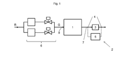
- FIG. 1 shows an arrangement of an internal combustion engine 1 with a arranged in the exhaust pipe 7 of the internal combustion engine 1 measuring device 2.
- the measuring device 2 comprises a catalyst unit 3 and at least one sensor 4 for determining the CO concentration in the exhaust gas. Shown in the figure is a sensor 4 downstream of the catalyst unit 3, as well as another - optional - sensor 4 upstream of the catalyst unit 3.
- the signals from the sensors for detecting the CO concentration in the exhaust gas are fed to a control / control unit 5.
- the internal combustion engine 1 is supplied via the propellant gas line 8 propellant G.
- a gas cleaning unit 6 is also shown in which untreated raw gas R is purified before it is supplied as fuel gas G to the internal combustion engine 1.
- the CO concentration of the exhaust gas downstream of the catalyst unit 3 is monitored.
- the sensor 4 detects an increase in the CO concentration in the exhaust gas.
- the control device 5 decides based on the signals, whether the gas cleaning unit 6 must be regenerated and / or the fuel gas engine 1 must be turned off.
- the control / regulation device 5 transmits commands to the gas cleaning unit 6 and / or the internal combustion engine 1 (signal lines are not shown).
- the CO concentration in the exhaust gas is monitored with a second sensor 4 also upstream of the catalyst unit 3.
- FIG. 2 shows an arrangement according to FIG. 1 , wherein the measuring device 2 is arranged here in a discharge line 7 'arranged in parallel to the exhaust pipe 7 in terms of flow.
- Advantage of in FIG. 2 shown arrangement is that only a portion of the exhaust gases of the internal combustion engine 1 must flow through the measuring device 2 and thus the catalyst unit 3 of the measuring device 2 can be made smaller and therefore less expensive.
- the arrangement of the sensors 4, as well as their interconnection that applies to FIG. 1 said.
Landscapes
- Engineering & Computer Science (AREA)
- Chemical & Material Sciences (AREA)
- Combustion & Propulsion (AREA)
- Mechanical Engineering (AREA)
- General Engineering & Computer Science (AREA)
- Chemical Kinetics & Catalysis (AREA)
- Health & Medical Sciences (AREA)
- Toxicology (AREA)
- Materials Engineering (AREA)
- Physics & Mathematics (AREA)
- Analytical Chemistry (AREA)
- General Chemical & Material Sciences (AREA)
- Oil, Petroleum & Natural Gas (AREA)
- General Physics & Mathematics (AREA)
- Exhaust Gas After Treatment (AREA)
- Combined Controls Of Internal Combustion Engines (AREA)
Abstract
Description
- Die Erfindung betrifft eine Verbrennungskraftmaschine mit den Merkmalen des Oberbegriffs von Anspruch 1 sowie ein Verfahren zum Betreiben einer solchen Verbrennungskraftmaschine mit den Merkmalen des Oberbegriffs von Anspruch 6.
- Eine interessante Anwendung von gasbetriebenen Verbrennungskraftmaschinen (Gasmotoren) besteht in der Nutzung von Gär- oder Deponiegasen, die in der Vergangenheit ungenutzt entsorgt, beispielsweise abgefackelt wurden. Diese Gase weisen häufig einen Brennwert auf, der sie zur Nutzung in Gasmotoren geeignet macht. Nachteilig an der Verwendung von Gär- oder Deponiegasen ist deren hoher Gehalt an Verunreinigungen, welche den Gasmotor schädigen können. Insbesondere sind dabei sogenannte volatile organic silicon compounds (VOSC) zu nennen, die meist aus Detergenzien stammen. Bei der Verbrennung im Gasmotor bildet sich aus diesen organischen Silizium-Verbindungen Silizium-Oxid, welches sich im Brennraum und benachbarten Komponenten ablagert und zu erheblichen Verschleißproblemen führt. Gasmotoren, die mit Gär- oder Deponiegas betrieben werden, weisen daher häufig eine vorgeschaltete Gasreinigungseinheit (meist mit Aktivkohlefiltern) auf, in welcher die organischen Silizium-Verbindungen aus dem Treibgas abgeschieden werden. Auch Schwefelwasserstoff und andere organische Verunreinigungen sowie Schwebeteilchen können damit entfernt werden. Für den sicheren Betrieb der Verbrennungskraftmaschine ist es wünschenswert, die Funktion der Gasreinigungseinheit anhand der Gasqualität des in der Gasreinigungseinheit gereinigten Brenngases zu überwachen.
Eine Online-Messung der Gasqualität nach genannten Gasreinigungseinheiten ist allerdings sehr kostspielig und daher für die meisten Anlagen nicht realisierbar. Offline-Messungen der Gasqualität über Entnahme von Gasproben oder die Analyse von Schmieröl, in welchem ebenfalls Silizium-Rückstände nachweisbar sind, brauchen mehrere Tage zur Analyse und sind daher auch ungeeignet, um die Wirkung der Filteranlage zu überwachen.
Es wird daher im Stand der Technik so vorgegangen, dass meist zwei strömungstechnisch parallele Filtereinheiten vorgesehen sind, von denen jeweils nur eine von dem zu reinigenden Brenngas durchströmt wird. Die Filtereinheiten werden alternierend regeneriert oder ausgetauscht, sodass stets eine "frische" Filtereinheit zu Verfügung steht. Nach festgelegten Intervallen wird die unverbrauchte Filtereinheit als Arbeitsfilter freigeschaltet und die verbrauchte Filtereinheit regeneriert.
Die Intervalle zur Regenerierung der Filtereinheiten werden dabei konservativ gewählt, sodass ein Übertritt von Silizium-Verbindungen oder anderen schädlichen organischen Verbindungen in die Verbrennungskraftmaschine weitgehend verhindert wird. Konservativ heißt, dass die Intervalle zur Regenerierung kurz gewählt werden, auch wenn dies vom aktuellen Belegungszustand der Filtereinheit gar nicht notwendig wäre. Diese Vorgehensweise ist natürlich unwirtschaftlich, da die Filtereinheiten weit häufiger regeneriert werden, als dies eigentlich notwendig wäre. Da man aber keine Kenntnis der aktuellen Gasqualität nach der Filteranlage hat, ist dies die einzig sichere Betriebsweise. - Aufgabe der vorliegenden Erfindung ist es, eine Verbrennungskraftmaschine mit einer Messeinrichtung zur Bestimmung der Gasqualität eines der Verbrennungskraftmaschine zuführbaren Brenngases sowie ein Verfahren zum Betreiben einer solchen Verbrennungskraftmaschine bereitzustellen, welche bzw. welches die Nachteile des Standes der Technik vermeidet.
- Gelöst wird diese Aufgabe durch eine Verbrennungskraftmaschine mit den Merkmalen von Anspruch 1, sowie einem Verfahren mit den Merkmalen von Anspruch 6. Vorteilhafte Ausführungsformen sind in den abhängigen Ansprüchen definiert.
- Dadurch dass eine Messeinrichtung zur Bestimmung der Gasqualität eines der Verbrennungskraftmaschine über die Zuführleitung zuführbaren Brenngases vorgesehen ist, wobei die Messeinrichtung zumindest eine Katalysatoreinheit umfasst, welcher Abgas aus Verbrennungskraftmaschine zuführbar ist zumindest einen stromabwärts der Katalysatoreinheit angeordneten Sensor zur Erfassung einer für die Umsatzrate der Katalysatoreinheit charakteristischen Größe umfasst, wobei durch die Messeinrichtung zur Bestimmung der Gasqualität abhängig von der durch den Sensor ermittelten, für die Umsatzrate der Katalysatoreinheit charakteristischen Größe die Gasqualität des der Verbrennungskraftmaschine zugeführten Brenngases bestimmbar ist, kann also erkannt werden, ob die der Verbrennungskraftmaschine vorgeschaltete Gasreinigungseinheit ordnungsgemäß arbeitet.
Die Erfindung macht sich die Erkenntnis zunutze, dass bei Übertritt von Verunreinigungen - hervorgerufen etwa durch eine nicht ordnungsgemäß arbeitende Gasreinigungseinheit in der Brenngaszufuhr der Verbrennungskraftmaschine, eine im Abgasstrom der Verbrennungskraftmaschine angeordnete Katalysatoreinheit dies durch Abfall der Umsatzrate registriert. Der Grund dafür ist die Maskierung der Katalysatoroberfläche der Katalysatoreinheit. Bei einem Durchbruch von organischen Siliziumverbindungen tritt eine Maskierung durch Siliziumoxid (Si02) ein. Tritt Schwefelwasserstoff (H2S) durch die Gasreinigungseinheit, so führt der Schwefel zu einer Maskierung der Katalysatoroberfläche der Katalysatoreinheit. Ein Durchbruch von partikulären Verunreinigungen kann ebenfalls zu einer Belegung der Katalysatoroberflächen führen. Durch die vorgeschlagene Anordnung ist die Umsatzrate bzw. eine Änderung der Umsatzrate der Katalysatoreinheit überwachbar und damit eine robuste Möglichkeit zur Bestimmung der Gasqualität geschaffen. - Zur Überwachung der Umsatzrate sind Sensoren geeignet, die ein Signal erzeugen abgeben können, welches indikativ für die Funktion der Katalysatoreinheit ist. In Betracht kommen z.B. Temperatursensoren, Sauerstoff-Sensoren oder CO-Sensoren. Bevorzugt ist vorgesehen, dass der Sensor ein Sensor zur Bestimmung der CO-Konzentration ist.
Sensoren zur Erfassung einer Kohlenmonoxid (CO) -Konzentration sind eine besonders günstige Möglichkeit, die Umsatzrate einer Katalysatoreinheit zu überwachen. Im unbehandelten Abgas nach der Verbrennungskraftmaschine sind stets gewisse Mengen an CO vorhanden, welche in einer Katalysatoreinheit oxidiert werden können. Damit ist die CO-Konzentration stromabwärts einer Katalysatoreinheit ein geeigneter Indikator für deren Funktionieren. Am Beispiel eines Temperatursensors würde man die Abnahme einer Umsatzrate der Katalysatoreinheit etwa durch sinkende Temperaturen feststellen, wenn die Katalysatoreinheit weniger CO oder unverbrannte Kohlenwasserstoffe umsetzt. - Bevorzugt kann vorgesehen sein, dass die Messeinrichtung wenigstens einen weiteren Sensor zur Bestimmung der CO-Konzentration stromaufwärts der Katalysatoreinheit umfasst. Mit dieser Anordnung ist die CO-Konzentration stromaufwärts und stromabwärts der Katalysatoreinheit bestimmbar. Dadurch ist eine noch genauere Überwachung der Umsatzrate der Katalysatoreinheit möglich als mit nur einem Sensor zur Bestimmung der CO-Konzentration stromabwärts der Katalysatoreinheit. Hier am Beispiel für den CO-Sensor formuliert, gilt der Vorteil dieser Anordnung natürlich auch für andere, weiter oben genannte Sensoren.
- Die Anordnung der Sensoren "stromaufwärts" und "stromabwärts" der Katalysatoreinheit bezeichnet ihre Lage in Bezug auf den Abgasstrom der Verbrennungskraftmaschine.
- Bevorzugt kann vorgesehen sein, dass die Messeinrichtung so angeordnet ist, dass nur ein Teil der Abgase der Verbrennungskraftmaschine die Messeinrichtung durchströmt. Dieses Ausführungsbeispiel beschreibt den Fall, nach welchem nur ein Teil des Abgasmassenstroms der Verbrennungskraftmaschine der Messeinrichtung zugeführt wird. Dies kann beispielsweise durch eine zur Abgasleitung parallele Entnahmeleitung realisiert sein, in welcher die Messeinrichtung angeordnet ist. Damit kann die Messeinrichtung klein und kostengünstig ausgebildet sein.
- Gemäß einer weiteren bevorzugten Ausführungsform kann vorgesehen sein, dass die Messeinrichtung von im Wesentlichen den gesamten Abgasen der Verbrennungskraftmaschine durchströmt wird. Dieses Ausführungsbeispiel beschreibt den Fall, nach welchem im Wesentlichen der gesamte Abgasmassenstrom der Verbrennungskraftmaschine durch die Katalysatoreinheit der Messeinrichtung tritt. Somit werden die Abgase der Verbrennungskraftmaschine von der Katalysatoreinheit der Messeinrichtung katalytisch gereinigt und die Messeinrichtung dient auch zur Abgasnachbehandlung der Verbrennungskraftmaschine.
- Als Verfahren ist vorgesehen, dass eine für die Umsatzrate der Katalysatoreinheit charakteristische Größe mittels des wenigstens einen Sensors gemessen wird und in Abhängigkeit der ermittelten für die Umsatzrate der Katalysatoreinheit charakteristischen Größe auf die Gasqualität des Brenngases geschlossen wird.
Bevorzugt ist vorgesehen, dass die für die Umsatzrate der Katalysatoreinheit charakteristische Größe die CO-Konzentration ist.
Wie weiter oben ausgeführt, bewirkt der Übertritt von organischen Verbindungen, insbesondere organischen Silizium-Verbindungen in die Verbrennungskraftmaschine - der Übertritt hervorgerufen etwa durch eine nicht ordnungsgemäß arbeitende Gasreinigungseinheit in der Brenngaszufuhr der Verbrennungskraftmaschine - einen Abfall der Umsatzrate einer im Abgasstrom der Verbrennungskraftmaschine angeordneten Katalysatoreinheit. Der Grund dafür ist die Maskierung der Katalysatoroberfläche durch die durchgebrochenen Spezies bzw. deren Verbrennungsprodukte.
Besonders bevorzugt kann vorgesehen sein, dass die für die Umsatzrate der Katalysatoreinheit charakteristische Größe stromaufwärts und stromabwärts der Katalysatoreinheit gemessen wird und in Abhängigkeit der gemessenen Differenz auf die Gasqualität des Brenngases geschlossen wird.
Gemäß einer Verfahrensvariante wird die CO-Konzentration stromaufwärts und stromabwärts der Katalysatoreinheit gemessen und so die Umsatzrate überwacht.
Durch die Messung der CO-Konzentration stromaufwärts und stromabwärts der Katalysatoreinheit kann die Umsatzrate der Katalysatoreinheit noch genauer erfasst werden. - Die Erfindung wird im weiteren durch die Figuren näher erläutert. Dabei zeigt
- Fig. 1
- eine Verbrennungskraftmaschine mit einer Messeinrichtung zur Bestimmung der Gasqualität,
- Fig. 2
- eine Verbrennungskraftmaschine gemäß einer alternativen Ausführungsform.
-
Figur 1 zeigt eine Anordnung einer Verbrennungskraftmaschine 1 mit einer in der Abgasleitung 7 der Verbrennungskraftmaschine 1 angeordneten Messeinrichtung 2. Die Messeinrichtung 2 umfasst eine Katalysatoreinheit 3 und wenigstens einen Sensor 4 zur Bestimmung der CO-Konzentration im Abgas. In der Abbildung gezeigt ist ein Sensor 4 stromabwärts der Katalysatoreinheit 3, sowie ein weiterer - optionaler - Sensor 4 stromaufwärts der Katalysatoreinheit 3. Die Signale der Sensoren zur Erfassung der CO-Konzentration im Abgas werden einer Regel-/Steuereinheit 5 zugeführt. Der Verbrennungskraftmaschine 1 wird über die Treibgasleitung 8 Treibgas G zugeführt. Der Vollständigkeit halber gezeigt ist auch eine Gasreinigungseinheit 6, in der unbehandeltes Rohgas R gereinigt wird, bevor es als Brenngas G der Verbrennungskraftmaschine 1 zugeführt wird. Über den Sensor 4 stromabwärts der Katalysatoreinheit 3 wird die CO-Konzentration des Abgases stromabwärts der Katalysatoreinheit 3 überwacht. Bei einem Durchbruch von Verunreinigungen aus dem Rohgas R in das Treibgas G detektiert der Sensor 4 eine Zunahme der CO-Konzentration im Abgas. Die Steuer-/Regeleinrichtung 5 entscheidet aufgrund der Signale, ob die Gasreinigungseinheit 6 regeneriert werden muss und/oder die Brenngasmaschine 1 abgestellt werden muss. Die Steuer-/Regeleinrichtung 5 übergibt dazu Befehle an die Gasreinigungseinheit 6 und/oder die Verbrennungskraftmaschine 1 (Signalleitungen sind nicht gezeigt). Optional wird die CO-Konzentration im Abgas mit einem zweiten Sensor 4 auch stromaufwärts der Katalysatoreinheit 3 überwacht. Durch diese Anordnung mit Sensoren 4 stromaufwärts und stromabwärts der Katalysatoreinheit 3 ist die Umsatzrate der Katalysatoreinrichtung 3 noch genauer überwachbar als mit lediglich einem Sensor 4 stromabwärts der Katalysatoreinheit 3. -
Figur 2 zeigt eine Anordnung gemäßFigur 1 , wobei die Messeinrichtung 2 hier in einer zur Abgasleitung 7 strömungstechnisch parallel angeordneten Entnahmeleitung 7' angeordnet ist. Vorteil der inFigur 2 gezeigten Anordnung ist es, dass lediglich ein Teil der Abgase der Verbrennungskraftmaschine 1 durch die Messeinrichtung 2 strömen müssen und somit die Katalysatoreinheit 3 der Messeinrichtung 2 kleiner und damit kostengünstiger ausgeführt werden kann. Bezüglich der Anordnung der Sensoren 4, sowie deren Verschaltung gilt das fürFigur 1 gesagte. - Die Figurenbeschreibungen sind beispielhaft für einen CO-Sensor formuliert, sie gelten natürlich auch für andere, in der Beschreibung der Erfindung genannte Sensoren, die ein Signal erzeugen abgeben können, welches indikativ für die Umsatzrate der Katalysatoreinheit 3 ist.
-
- 1
- Verbrennungskraftmaschine
- 2
- Messeinrichtung
- 3
- Katalysatoreinheit
- 4
- Sensor(en)
- 5
- Steuer-/Regeleinrichtung
- 6
- Gasreinigungseinrichtung
- 7
- Abgasleitung
- 7'
- Abgasentnahmeleitung
- 8
- Brenngaszuführleitung
- G
- Brenngas
- R
- Rohgas
Claims (8)
- Verbrennungskraftmaschine (1), umfassend:- zumindest einen Zylinder,- zumindest eine Zuführleitung (8) für Brenngas (G),- zumindest eine Abgasleitung (7, 7') zur Abführung von Abgas aus der Verbrennungskraftmaschine (1),
dadurch gekennzeichnet, dass eine Messeinrichtung (2) zur Bestimmung der Gasqualität eines der Verbrennungskraftmaschine (1) über die Zuführleitung (8) zuführbaren Brenngases (G) vorgesehen ist, wobei die Messeinrichtung (2) zumindest eine Katalysatoreinheit (3) umfasst, welcher Abgas aus Verbrennungskraftmaschine (1) zuführbar ist und zumindest einen stromabwärts der Katalysatoreinheit (3) angeordneten Sensor (4) zur Erfassung einer für die Umsatzrate der Katalysatoreinheit (3) charakteristischen Größe umfasst, wobei durch die Messeinrichtung (2) zur Bestimmung der Gasqualität abhängig von der durch den Sensor (4) ermittelten, für die Umsatzrate der Katalysatoreinheit (3) charakteristischen, Größe die Gasqualität des der Verbrennungskraftmaschine (1) zugeführten Brenngases (G) bestimmbar ist. - Verbrennungskraftmaschine (1) nach Anspruch 1, dadurch gekennzeichnet, dass der Sensor (4) ein Sensor zur Bestimmung der CO-Konzentration ist.
- Verbrennungskraftmaschine (1) nach Anspruch 1 oder 2, dadurch gekennzeichnet, dass die Messeinrichtung (2) wenigstens einen weiteren Sensor (4) stromaufwärts der Katalysatoreinheit (3) umfasst.
- Verbrennungskraftmaschine (1) nach wenigstens einem der Ansprüche 1 bis 3, dadurch gekennzeichnet, dass die Messeinrichtung (2) so angeordnet ist, dass nur ein Teil der Abgase der Verbrennungskraftmaschine (1) die Messeinrichtung (2) durchströmt.
- Verbrennungskraftmaschine (1) nach wenigstens einem der Ansprüche 1 bis 3, dadurch gekennzeichnet, dass die Messeinrichtung (2) von im Wesentlichen den gesamten Abgasen der Verbrennungskraftmaschine (1) durchströmt wird.
- Verfahren zum Betreiben einer Verbrennungskraftmaschine (1) nach wenigstens einem der Ansprüche 1 bis 5, dadurch gekennzeichnet, dass eine für die Umsatzrate der Katalysatoreinheit (3) charakteristische Größe mittels des wenigstens einen Sensors (4) gemessen wird und in Abhängigkeit der ermittelten für die Umsatzrate der Katalysatoreinheit (3) charakteristischen Größe auf die Gasqualität des Brenngases (G) geschlossen wird.
- Verfahren nach Anspruch 6, dadurch gekennzeichnet, dass die für die Umsatzrate der Katalysatoreinheit (3) charakteristische Größe die CO-Konzentration ist.
- Verfahren nach Anspruch 6 oder 7, dadurch gekennzeichnet, dass die für die Umsatzrate der Katalysatoreinheit (3) charakteristische Größe stromaufwärts und stromabwärts der Katalysatoreinheit (3) gemessen wird und in Abhängigkeit der gemessenen Differenz auf die Gasqualität des Brenngases (G) geschlossen wird.
Applications Claiming Priority (1)
| Application Number | Priority Date | Filing Date | Title |
|---|---|---|---|
| ATA573/2014A AT516098B1 (de) | 2014-07-21 | 2014-07-21 | Verbrennungskraftmaschine |
Publications (2)
| Publication Number | Publication Date |
|---|---|
| EP2977579A1 true EP2977579A1 (de) | 2016-01-27 |
| EP2977579B1 EP2977579B1 (de) | 2016-11-09 |
Family
ID=53835197
Family Applications (1)
| Application Number | Title | Priority Date | Filing Date |
|---|---|---|---|
| EP15002143.4A Not-in-force EP2977579B1 (de) | 2014-07-21 | 2015-07-18 | Verbrennungskraftmaschine |
Country Status (7)
| Country | Link |
|---|---|
| US (1) | US20160018290A1 (de) |
| EP (1) | EP2977579B1 (de) |
| JP (1) | JP6105682B2 (de) |
| KR (1) | KR20160011166A (de) |
| CN (1) | CN105275640A (de) |
| AT (1) | AT516098B1 (de) |
| BR (1) | BR102015017268A2 (de) |
Families Citing this family (3)
| Publication number | Priority date | Publication date | Assignee | Title |
|---|---|---|---|---|
| SE541091C2 (en) * | 2016-03-23 | 2019-04-02 | Scania Cv Ab | A method and a system for adapting engine control of a gas engine in a vehicle |
| US10321114B2 (en) * | 2016-08-04 | 2019-06-11 | Google Llc | Testing 3D imaging systems |
| CN110836152B (zh) * | 2019-11-28 | 2021-12-17 | 广平县隆合新能源销售有限公司 | 一种降噪低排放新能源汽车 |
Citations (2)
| Publication number | Priority date | Publication date | Assignee | Title |
|---|---|---|---|---|
| EP0894959A2 (de) * | 1997-08-02 | 1999-02-03 | Mannesmann VDO Aktiengesellschaft | Vorsteuerwertekorrektur bei Brennkraftmaschinen |
| DE19924500C1 (de) * | 1999-05-28 | 2000-08-24 | Daimler Chrysler Ag | Verfahren zum Betrieb einer gasgespeisten Brennkraftmaschine |
Family Cites Families (11)
| Publication number | Priority date | Publication date | Assignee | Title |
|---|---|---|---|---|
| US5703777A (en) * | 1994-10-20 | 1997-12-30 | Anr Pipeline Company | Parametric emissions monitoring system having operating condition deviation feedback |
| US5899187A (en) * | 1996-07-11 | 1999-05-04 | Jenbacher Energiesysteme Aktiengesellschaft | Engine arrangement |
| JP3549147B2 (ja) * | 1997-11-25 | 2004-08-04 | 本田技研工業株式会社 | 天然ガス用内燃機関の触媒劣化検出装置 |
| JP4387048B2 (ja) * | 2000-08-02 | 2009-12-16 | 本田技研工業株式会社 | 天然ガスエンジンの排気浄化装置および排気浄化方法 |
| US7987662B2 (en) * | 2007-10-31 | 2011-08-02 | Ford Global Technologies, Llc | Composition and method for controlling excessive exhaust gas temperatures |
| US8161731B2 (en) * | 2008-05-12 | 2012-04-24 | Caterpillar Inc. | Selective catalytic reduction using controlled catalytic deactivation |
| JP5402708B2 (ja) * | 2010-02-16 | 2014-01-29 | トヨタ自動車株式会社 | 内燃機関の制御装置 |
| KR20130031750A (ko) * | 2011-09-21 | 2013-03-29 | 동아대학교 산학협력단 | 마이크로웨이브 센싱 방식의 차량의 배기가스 모니터링 시스템 및 방법 |
| JP2014062510A (ja) * | 2012-09-21 | 2014-04-10 | Yanmar Co Ltd | 内燃機関 |
| JP5386768B2 (ja) * | 2012-11-19 | 2014-01-15 | 独立行政法人交通安全環境研究所 | Lpgエンジンの空燃比制御方法及び空燃比制御装置 |
| US9057301B2 (en) * | 2013-07-02 | 2015-06-16 | General Electric Company | Emissions control in stationary rich burn engines |
-
2014
- 2014-07-21 AT ATA573/2014A patent/AT516098B1/de not_active IP Right Cessation
-
2015
- 2015-07-09 US US14/795,192 patent/US20160018290A1/en not_active Abandoned
- 2015-07-15 JP JP2015140940A patent/JP6105682B2/ja not_active Expired - Fee Related
- 2015-07-18 EP EP15002143.4A patent/EP2977579B1/de not_active Not-in-force
- 2015-07-20 KR KR1020150102686A patent/KR20160011166A/ko not_active Ceased
- 2015-07-20 BR BR102015017268A patent/BR102015017268A2/pt not_active Application Discontinuation
- 2015-07-21 CN CN201510430076.2A patent/CN105275640A/zh active Pending
Patent Citations (2)
| Publication number | Priority date | Publication date | Assignee | Title |
|---|---|---|---|---|
| EP0894959A2 (de) * | 1997-08-02 | 1999-02-03 | Mannesmann VDO Aktiengesellschaft | Vorsteuerwertekorrektur bei Brennkraftmaschinen |
| DE19924500C1 (de) * | 1999-05-28 | 2000-08-24 | Daimler Chrysler Ag | Verfahren zum Betrieb einer gasgespeisten Brennkraftmaschine |
Also Published As
| Publication number | Publication date |
|---|---|
| CN105275640A (zh) | 2016-01-27 |
| KR20160011166A (ko) | 2016-01-29 |
| US20160018290A1 (en) | 2016-01-21 |
| JP6105682B2 (ja) | 2017-03-29 |
| JP2016029279A (ja) | 2016-03-03 |
| EP2977579B1 (de) | 2016-11-09 |
| AT516098A1 (de) | 2016-02-15 |
| AT516098B1 (de) | 2016-08-15 |
| BR102015017268A2 (pt) | 2016-01-26 |
Similar Documents
| Publication | Publication Date | Title |
|---|---|---|
| EP1992935B1 (de) | Verfahren zum Betreiben eines stromabwärts nach einem Partikelfilter angeordneten Partikelsensors und Vorrichtung zur Durchführung des Verfahrens | |
| DE102007014761B4 (de) | Verfahren zum Betreiben eines sammelnden Partikelsensors und Vorrichtung zur Durchführung des Verfahrens | |
| DE102014209810B4 (de) | Verfahren und Vorrichtung zur Erkennung einer Ruß- und Aschebeladung eines Partikelfilters | |
| DE112007003140T5 (de) | Sensorabnormalitätsdetektionsvorrichtung und Sensorabnormalitätsdetektionsverfahren | |
| EP2977579B1 (de) | Verbrennungskraftmaschine | |
| DE102009046749A1 (de) | Vorrichtung zum Betrieb eines Partikelsensors | |
| DE102010027975A1 (de) | Verfahren und Vorrichtung zur Eigendiagnose einer Abgassonde | |
| DE102016122315A1 (de) | System und Verfahren zur Fehlerdiagnose in einem Emissionssteuerungssystem | |
| DE102014100766B4 (de) | Verfahren und Vorrichtung zum Prüfen von Diesel-Partikelfiltern (DPF) | |
| DE102019102880A1 (de) | Verfahren zum Bestimmen des Beladungszustands eines Filterelements eines Filtersystems, Filtersystem und Brennstoffzellensystem | |
| DE102015015153B4 (de) | Verfahren zur Überprüfung einer Pumpeneinrichtung in einem Gasmessystem | |
| DE102009001064A1 (de) | Verfahren zum Ermitteln eines Maßes für einen Wassertropfeneintrag in den Abgaskanal einer Brennkraftmaschine und Vorrichtung zur Durchführung des Verfahrens | |
| EP3693718B1 (de) | Vorrichtung und verfahren zur extraktiven kontinuierlichen messung von partikeln | |
| AT510407B1 (de) | Filterprüfeinrichtung | |
| DE102014209972B4 (de) | Verfahren und Vorrichtung zum Bewerten des Alterungszustandeseines NOx-Speicherkatalysators | |
| AT403852B (de) | Verfahren zum messen von schadstoffen in gasen und vorrichtung zur durchführung des verfahrens | |
| DE102007009873A1 (de) | Verfahren zur Erkennung des Auftretens von Querempfindlichkeiten eines Abgassensors | |
| EP3948997A1 (de) | Diagnosesystem für zustandsorientierte instandhaltung von brennstoffzellenfiltern | |
| AT518900B1 (de) | Abgasanalysesystem zur Bestimmung der Konzentration chemischer Komponenten in Abgasströmen | |
| DE102018220729A1 (de) | Verfahren und Vorrichtung zur Bestimmung einer Partikelbeladung eines Partikelfilters | |
| EP3332861A1 (de) | Trockenluftsystem für granulattrockner | |
| EP3004617B1 (de) | Verfahren zur durchbruchsüberwachung eines kraftstoffdampfbehälter | |
| DE102005055464B4 (de) | Verfahren zum Ermitteln und/oder Überwachen der Wirksamkeit eines Filters | |
| DE102011006923A1 (de) | Vorrichtung und Verfahren zur Diagnose der Funktion eines Partikelsensors | |
| DE102009024223A1 (de) | Anlage zur Wiederverwendung von Ammoniak |
Legal Events
| Date | Code | Title | Description |
|---|---|---|---|
| PUAI | Public reference made under article 153(3) epc to a published international application that has entered the european phase |
Free format text: ORIGINAL CODE: 0009012 |
|
| AK | Designated contracting states |
Kind code of ref document: A1 Designated state(s): AL AT BE BG CH CY CZ DE DK EE ES FI FR GB GR HR HU IE IS IT LI LT LU LV MC MK MT NL NO PL PT RO RS SE SI SK SM TR |
|
| AX | Request for extension of the european patent |
Extension state: BA ME |
|
| 17P | Request for examination filed |
Effective date: 20160219 |
|
| RBV | Designated contracting states (corrected) |
Designated state(s): AL AT BE BG CH CY CZ DE DK EE ES FI FR GB GR HR HU IE IS IT LI LT LU LV MC MK MT NL NO PL PT RO RS SE SI SK SM TR |
|
| GRAP | Despatch of communication of intention to grant a patent |
Free format text: ORIGINAL CODE: EPIDOSNIGR1 |
|
| RIC1 | Information provided on ipc code assigned before grant |
Ipc: F02D 41/00 20060101ALI20160428BHEP Ipc: F01N 3/10 20060101ALI20160428BHEP Ipc: F01N 9/00 20060101AFI20160428BHEP Ipc: F02D 41/14 20060101ALI20160428BHEP Ipc: F02M 21/02 20060101ALI20160428BHEP Ipc: G01M 15/10 20060101ALI20160428BHEP |
|
| INTG | Intention to grant announced |
Effective date: 20160530 |
|
| GRAS | Grant fee paid |
Free format text: ORIGINAL CODE: EPIDOSNIGR3 |
|
| GRAA | (expected) grant |
Free format text: ORIGINAL CODE: 0009210 |
|
| RAP1 | Party data changed (applicant data changed or rights of an application transferred) |
Owner name: GE JENBACHER GMBH & CO OG |
|
| AK | Designated contracting states |
Kind code of ref document: B1 Designated state(s): AL AT BE BG CH CY CZ DE DK EE ES FI FR GB GR HR HU IE IS IT LI LT LU LV MC MK MT NL NO PL PT RO RS SE SI SK SM TR |
|
| REG | Reference to a national code |
Ref country code: GB Ref legal event code: FG4D Free format text: NOT ENGLISH |
|
| REG | Reference to a national code |
Ref country code: AT Ref legal event code: REF Ref document number: 844143 Country of ref document: AT Kind code of ref document: T Effective date: 20161115 Ref country code: CH Ref legal event code: EP |
|
| REG | Reference to a national code |
Ref country code: IE Ref legal event code: FG4D Free format text: LANGUAGE OF EP DOCUMENT: GERMAN |
|
| REG | Reference to a national code |
Ref country code: DE Ref legal event code: R096 Ref document number: 502015000280 Country of ref document: DE |
|
| PG25 | Lapsed in a contracting state [announced via postgrant information from national office to epo] |
Ref country code: LV Free format text: LAPSE BECAUSE OF FAILURE TO SUBMIT A TRANSLATION OF THE DESCRIPTION OR TO PAY THE FEE WITHIN THE PRESCRIBED TIME-LIMIT Effective date: 20161109 |
|
| REG | Reference to a national code |
Ref country code: LT Ref legal event code: MG4D |
|
| REG | Reference to a national code |
Ref country code: NL Ref legal event code: MP Effective date: 20161109 |
|
| PG25 | Lapsed in a contracting state [announced via postgrant information from national office to epo] |
Ref country code: LT Free format text: LAPSE BECAUSE OF FAILURE TO SUBMIT A TRANSLATION OF THE DESCRIPTION OR TO PAY THE FEE WITHIN THE PRESCRIBED TIME-LIMIT Effective date: 20161109 Ref country code: NL Free format text: LAPSE BECAUSE OF FAILURE TO SUBMIT A TRANSLATION OF THE DESCRIPTION OR TO PAY THE FEE WITHIN THE PRESCRIBED TIME-LIMIT Effective date: 20161109 Ref country code: GR Free format text: LAPSE BECAUSE OF FAILURE TO SUBMIT A TRANSLATION OF THE DESCRIPTION OR TO PAY THE FEE WITHIN THE PRESCRIBED TIME-LIMIT Effective date: 20170210 Ref country code: SE Free format text: LAPSE BECAUSE OF FAILURE TO SUBMIT A TRANSLATION OF THE DESCRIPTION OR TO PAY THE FEE WITHIN THE PRESCRIBED TIME-LIMIT Effective date: 20161109 Ref country code: NO Free format text: LAPSE BECAUSE OF FAILURE TO SUBMIT A TRANSLATION OF THE DESCRIPTION OR TO PAY THE FEE WITHIN THE PRESCRIBED TIME-LIMIT Effective date: 20170209 |
|
| PG25 | Lapsed in a contracting state [announced via postgrant information from national office to epo] |
Ref country code: PL Free format text: LAPSE BECAUSE OF FAILURE TO SUBMIT A TRANSLATION OF THE DESCRIPTION OR TO PAY THE FEE WITHIN THE PRESCRIBED TIME-LIMIT Effective date: 20161109 Ref country code: IS Free format text: LAPSE BECAUSE OF FAILURE TO SUBMIT A TRANSLATION OF THE DESCRIPTION OR TO PAY THE FEE WITHIN THE PRESCRIBED TIME-LIMIT Effective date: 20170309 Ref country code: PT Free format text: LAPSE BECAUSE OF FAILURE TO SUBMIT A TRANSLATION OF THE DESCRIPTION OR TO PAY THE FEE WITHIN THE PRESCRIBED TIME-LIMIT Effective date: 20170309 Ref country code: RS Free format text: LAPSE BECAUSE OF FAILURE TO SUBMIT A TRANSLATION OF THE DESCRIPTION OR TO PAY THE FEE WITHIN THE PRESCRIBED TIME-LIMIT Effective date: 20161109 Ref country code: HR Free format text: LAPSE BECAUSE OF FAILURE TO SUBMIT A TRANSLATION OF THE DESCRIPTION OR TO PAY THE FEE WITHIN THE PRESCRIBED TIME-LIMIT Effective date: 20161109 Ref country code: ES Free format text: LAPSE BECAUSE OF FAILURE TO SUBMIT A TRANSLATION OF THE DESCRIPTION OR TO PAY THE FEE WITHIN THE PRESCRIBED TIME-LIMIT Effective date: 20161109 |
|
| PG25 | Lapsed in a contracting state [announced via postgrant information from national office to epo] |
Ref country code: CZ Free format text: LAPSE BECAUSE OF FAILURE TO SUBMIT A TRANSLATION OF THE DESCRIPTION OR TO PAY THE FEE WITHIN THE PRESCRIBED TIME-LIMIT Effective date: 20161109 Ref country code: EE Free format text: LAPSE BECAUSE OF FAILURE TO SUBMIT A TRANSLATION OF THE DESCRIPTION OR TO PAY THE FEE WITHIN THE PRESCRIBED TIME-LIMIT Effective date: 20161109 Ref country code: RO Free format text: LAPSE BECAUSE OF FAILURE TO SUBMIT A TRANSLATION OF THE DESCRIPTION OR TO PAY THE FEE WITHIN THE PRESCRIBED TIME-LIMIT Effective date: 20161109 Ref country code: DK Free format text: LAPSE BECAUSE OF FAILURE TO SUBMIT A TRANSLATION OF THE DESCRIPTION OR TO PAY THE FEE WITHIN THE PRESCRIBED TIME-LIMIT Effective date: 20161109 Ref country code: SK Free format text: LAPSE BECAUSE OF FAILURE TO SUBMIT A TRANSLATION OF THE DESCRIPTION OR TO PAY THE FEE WITHIN THE PRESCRIBED TIME-LIMIT Effective date: 20161109 |
|
| REG | Reference to a national code |
Ref country code: DE Ref legal event code: R097 Ref document number: 502015000280 Country of ref document: DE |
|
| PG25 | Lapsed in a contracting state [announced via postgrant information from national office to epo] |
Ref country code: SM Free format text: LAPSE BECAUSE OF FAILURE TO SUBMIT A TRANSLATION OF THE DESCRIPTION OR TO PAY THE FEE WITHIN THE PRESCRIBED TIME-LIMIT Effective date: 20161109 Ref country code: IT Free format text: LAPSE BECAUSE OF FAILURE TO SUBMIT A TRANSLATION OF THE DESCRIPTION OR TO PAY THE FEE WITHIN THE PRESCRIBED TIME-LIMIT Effective date: 20161109 Ref country code: BG Free format text: LAPSE BECAUSE OF FAILURE TO SUBMIT A TRANSLATION OF THE DESCRIPTION OR TO PAY THE FEE WITHIN THE PRESCRIBED TIME-LIMIT Effective date: 20170209 |
|
| PLBE | No opposition filed within time limit |
Free format text: ORIGINAL CODE: 0009261 |
|
| STAA | Information on the status of an ep patent application or granted ep patent |
Free format text: STATUS: NO OPPOSITION FILED WITHIN TIME LIMIT |
|
| 26N | No opposition filed |
Effective date: 20170810 |
|
| PG25 | Lapsed in a contracting state [announced via postgrant information from national office to epo] |
Ref country code: SI Free format text: LAPSE BECAUSE OF FAILURE TO SUBMIT A TRANSLATION OF THE DESCRIPTION OR TO PAY THE FEE WITHIN THE PRESCRIBED TIME-LIMIT Effective date: 20161109 |
|
| REG | Reference to a national code |
Ref country code: IE Ref legal event code: MM4A |
|
| REG | Reference to a national code |
Ref country code: FR Ref legal event code: ST Effective date: 20180330 |
|
| PG25 | Lapsed in a contracting state [announced via postgrant information from national office to epo] |
Ref country code: IE Free format text: LAPSE BECAUSE OF NON-PAYMENT OF DUE FEES Effective date: 20170718 |
|
| REG | Reference to a national code |
Ref country code: BE Ref legal event code: MM Effective date: 20170731 |
|
| PG25 | Lapsed in a contracting state [announced via postgrant information from national office to epo] |
Ref country code: FR Free format text: LAPSE BECAUSE OF NON-PAYMENT OF DUE FEES Effective date: 20170731 |
|
| PG25 | Lapsed in a contracting state [announced via postgrant information from national office to epo] |
Ref country code: LU Free format text: LAPSE BECAUSE OF NON-PAYMENT OF DUE FEES Effective date: 20170718 |
|
| PG25 | Lapsed in a contracting state [announced via postgrant information from national office to epo] |
Ref country code: BE Free format text: LAPSE BECAUSE OF NON-PAYMENT OF DUE FEES Effective date: 20170731 |
|
| PG25 | Lapsed in a contracting state [announced via postgrant information from national office to epo] |
Ref country code: MT Free format text: LAPSE BECAUSE OF FAILURE TO SUBMIT A TRANSLATION OF THE DESCRIPTION OR TO PAY THE FEE WITHIN THE PRESCRIBED TIME-LIMIT Effective date: 20161109 |
|
| REG | Reference to a national code |
Ref country code: CH Ref legal event code: PL |
|
| PG25 | Lapsed in a contracting state [announced via postgrant information from national office to epo] |
Ref country code: CH Free format text: LAPSE BECAUSE OF NON-PAYMENT OF DUE FEES Effective date: 20180731 Ref country code: LI Free format text: LAPSE BECAUSE OF NON-PAYMENT OF DUE FEES Effective date: 20180731 |
|
| PG25 | Lapsed in a contracting state [announced via postgrant information from national office to epo] |
Ref country code: MC Free format text: LAPSE BECAUSE OF FAILURE TO SUBMIT A TRANSLATION OF THE DESCRIPTION OR TO PAY THE FEE WITHIN THE PRESCRIBED TIME-LIMIT Effective date: 20161109 Ref country code: HU Free format text: LAPSE BECAUSE OF FAILURE TO SUBMIT A TRANSLATION OF THE DESCRIPTION OR TO PAY THE FEE WITHIN THE PRESCRIBED TIME-LIMIT; INVALID AB INITIO Effective date: 20150718 |
|
| PGFP | Annual fee paid to national office [announced via postgrant information from national office to epo] |
Ref country code: FI Payment date: 20190624 Year of fee payment: 5 |
|
| PG25 | Lapsed in a contracting state [announced via postgrant information from national office to epo] |
Ref country code: CY Free format text: LAPSE BECAUSE OF FAILURE TO SUBMIT A TRANSLATION OF THE DESCRIPTION OR TO PAY THE FEE WITHIN THE PRESCRIBED TIME-LIMIT Effective date: 20161109 |
|
| PGFP | Annual fee paid to national office [announced via postgrant information from national office to epo] |
Ref country code: DE Payment date: 20190620 Year of fee payment: 5 |
|
| PG25 | Lapsed in a contracting state [announced via postgrant information from national office to epo] |
Ref country code: MK Free format text: LAPSE BECAUSE OF FAILURE TO SUBMIT A TRANSLATION OF THE DESCRIPTION OR TO PAY THE FEE WITHIN THE PRESCRIBED TIME-LIMIT Effective date: 20161109 |
|
| GBPC | Gb: european patent ceased through non-payment of renewal fee |
Effective date: 20190718 |
|
| PG25 | Lapsed in a contracting state [announced via postgrant information from national office to epo] |
Ref country code: TR Free format text: LAPSE BECAUSE OF FAILURE TO SUBMIT A TRANSLATION OF THE DESCRIPTION OR TO PAY THE FEE WITHIN THE PRESCRIBED TIME-LIMIT Effective date: 20161109 |
|
| PG25 | Lapsed in a contracting state [announced via postgrant information from national office to epo] |
Ref country code: GB Free format text: LAPSE BECAUSE OF NON-PAYMENT OF DUE FEES Effective date: 20190718 |
|
| PG25 | Lapsed in a contracting state [announced via postgrant information from national office to epo] |
Ref country code: AL Free format text: LAPSE BECAUSE OF FAILURE TO SUBMIT A TRANSLATION OF THE DESCRIPTION OR TO PAY THE FEE WITHIN THE PRESCRIBED TIME-LIMIT Effective date: 20161109 |
|
| REG | Reference to a national code |
Ref country code: DE Ref legal event code: R119 Ref document number: 502015000280 Country of ref document: DE |
|
| REG | Reference to a national code |
Ref country code: FI Ref legal event code: MAE |
|
| PG25 | Lapsed in a contracting state [announced via postgrant information from national office to epo] |
Ref country code: FI Free format text: LAPSE BECAUSE OF NON-PAYMENT OF DUE FEES Effective date: 20200718 |
|
| PG25 | Lapsed in a contracting state [announced via postgrant information from national office to epo] |
Ref country code: DE Free format text: LAPSE BECAUSE OF NON-PAYMENT OF DUE FEES Effective date: 20210202 |
|
| REG | Reference to a national code |
Ref country code: AT Ref legal event code: MM01 Ref document number: 844143 Country of ref document: AT Kind code of ref document: T Effective date: 20200718 |
|
| PG25 | Lapsed in a contracting state [announced via postgrant information from national office to epo] |
Ref country code: AT Free format text: LAPSE BECAUSE OF NON-PAYMENT OF DUE FEES Effective date: 20200718 |